1
7.11.5
Motor Time Out
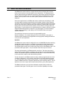
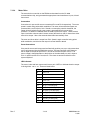
For all types of pan/tilt drives a motor time-out exists in software, i.e. should a pan/tilt run
to the end stop and the limit switch not shut the unit off, the software will stop the drive
after a period of four (4) minutes for any direction.
7.11.6
Tamper Alarm Input
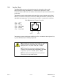
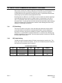
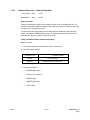
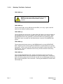
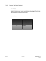
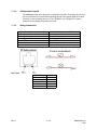
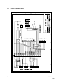
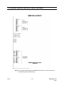
The tamper alarm input can be used to secure the control cabinet and/or the camera
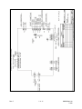
housing. The connections are made at PL10, and an open circuit between the two
terminals indicates an alarm condition. This will be detected by the motor control microcontroller, which will pass a message to the CC-2000 communications controller. This in
turn sends a message to the MAXPRO-Net Server.
7.11.7
Installation Notes
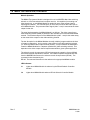
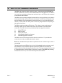
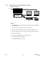
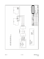
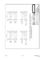
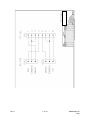
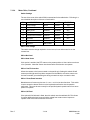
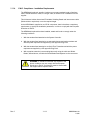
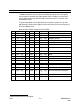
After all connections are made and the dip switches are set, the pan/tilt unit must be
manually controlled and the limit switches on the pan and tilt functions set. This is done
inside the pan/tilt unit itself and is not a site receiver function. With the limit switches set
the unit must be driven from stop to stop in every direction to allow the preset pots to
clutch into the correct position.
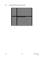
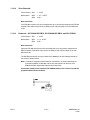
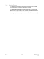
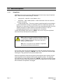
After all these mechanical and electrical settings have been done, press the initialize
button labeled SW1. The PTZ will then go through an initializing phase that operates all
the PTZ functions. This allows the site receiver to measure the direction of voltage
tracking for the presets and make auto reversals if required. If the site detects presets,
then the lens will track “fully zoom in” and “fully zoom out” then return to the spot it was
set at previously. This is to range the zoom for auto speed control, and this auto set-up
may take up to 10 seconds.
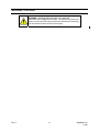
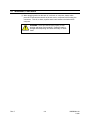
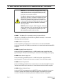
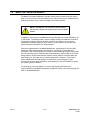
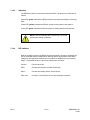
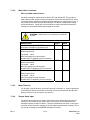
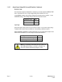
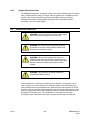
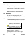
CAUTION: All directional control settings and lens
controls must be set and tested to be correct from one of
the system keyboards prior to this final RESET being
pressed. i.e. SW3-4 and SW3-5 must be set correctly.
7.11.8
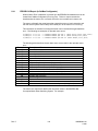
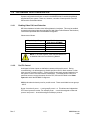
Suitable cable sizing for PTZ heads when connecting to Site Receivers
As it is not unusual for Pan-Tilt heads to operate on relatively high current, it is imperative
that cable with adequate conductor size is installed between the PTZ site receiver and
the PTZ head.
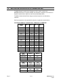
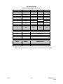
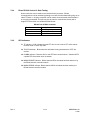
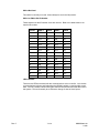
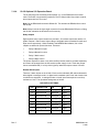
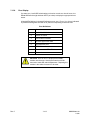
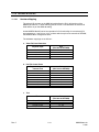
The following table indicates the recommended cable conductor size based on cable
feed distance.
Rev. C
Cable Feed
Distance
Cross Sectional Area
of Conductor
5m
1.0mm (17 AWG)
10m
1.0mm (17 AWG)
15m
1.5mm (15 AWG)
20m
1.5mm (15 AWG)
30m
2.5mm (10 AWG)
7.11-8
HMXMU001018
10/06