1
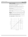
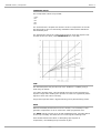
2264ALB
Limiter
Compressor
User Manual
527 – 402
Issue 1.2
2264ALB Limiter / Compressor
Issue 1.2
Health & Safety Notice
For your own safety and for the protection of others,
please observe the following safety precautions:
•Read these instructions.
•Keep these instructions.
•Follow all instructions.
•Only use attachments/accessories specified by the manufacturer.
•Heed all safety warnings.
•Do not use near water.
•Clean only with a dry cloth.
•Do not install near heat sources.
•Do not block ventilation openings.
•Unplug when unused for long periods of time.
•Refer all servicing to qualified personnel only.
AMS NEVE
Billington Road
Burnley
Lancs
BB11 5UB
England
Phone +44 (0)1282 457011
Fax: +44 (0)1282 417282
Info: [email protected]
Web: www.ams-neve.com
Support: http://www.ams-neve.com/support
© 2013 AMS Neve Ltd own the copyright of all information and drawings contained in this manual which are not to be copied or
reproduced by any means or disclosed in part or whole to any third party without written permission.
As part of our policy of continual product improvement, we reserve the right to alter specifications without notice but with due regard to
all current legislation.
Disclaimer: The information in this manual has been carefully checked and is believed to be accurate at the time of publication.
However, no responsibility is taken by us for inaccuracies, errors or omissions nor any liability assumed for any loss or damage
resulting either directly or indirectly from use of the information contained within it.
Trademarks: All trademarks are the property of their respective owners and are hereby acknowledged.
-2-
2264ALB Limiter / Compressor
Issue 1.2
Table of Contents
Health & Safety Notice........................................................................................2
Introduction .......................................................................................................4
Front Panel Controls ...........................................................................................5
LIM THR, REC, LIM I/O (Limiter Section) ..............................................................5
COMP THR, REC, COMP I/O (Compressor Section) .................................................5
COMP GAIN, RATIO, LINK (Compressor Section) ...................................................5
BYPASS / IN .....................................................................................................6
SA (Slow Attack) ...............................................................................................6
SIG (Signal Presence) ........................................................................................6
Meter LEDs .......................................................................................................6
2264 Operation ..................................................................................................7
LIMITING – ATTACKTIME ....................................................................................7
COMPRESS RATIO .............................................................................................8
THRESHOLD .....................................................................................................8
GAIN ................................................................................................................8
Limiter & Compressor in combination ...................................................................9
BYPASS Switch ..................................................................................................9
LINK ................................................................................................................9
Insert Mode ......................................................................................................10
Standalone Mode (Factory Default) ....................................................................10
Insert Mode (for use with 1073LB) .....................................................................10
Insert Mode Configuration Examples ..................................................................11
Unit Specifications............................................................................................12
In the unlikely even that this unit should malfunction or develop a
fault, then please register the fault details on our website, by
clicking the link below.
You will also need to enter the unit's serial number when you do
this, so please have this to hand.
http://www.ams-neve.info/crm/fault_report.html
Once the fault details have been registered, one of our technical
support team will be in touch via email.
This link should also be used for further operational or technical
help, or any general enquiry about the unit.
-3-
2264ALB Limiter / Compressor
Issue 1.2
Introduction
The 2264A LB Limiter / Compressor facilities and performance are
similar to those of a 2254/R Limiter Compressor.
The main advantages of the 2264A LB are its smaller size and
compatibility with LunchboxTM racks, plus it uses a more advanced circuit
technique, and the response curves it produces are more precise than
those of a 2254/R.
Also it has a switchable Slow Attack feature for applications such as Bus
Compression.
The 2264A LB Limiter / Compressor has been designed for use in
sound broadcast and recording studios where a requirement exists for a
high quality instrument for the control of programme dynamic range.
The unit may also be used for the protection of transmitters from
overloading when the limiter is adjusted for a shorter attack time.
The operational controls and metering are mounted on the front panel of
the unit.
-4-
2264ALB Limiter / Compressor
Issue 1.2
Front Panel Controls
LIM THR, REC, LIM I/O (Limiter Section)
This is a 3-function group of controls comprising the following functions:
•
LIMit THReshold
The inner grey knob, variable from +4dBm to +15dBm, controls the
threshold at which the limiting effect takes place.
•
Limit RECovery
The outer metal knob, a switched attenuator with notched settings from
50ms to 800 ms, controls the recovery time of the Limiter. There are also
two Auto settings, A1 and A2.
•
LIMit In/Out
Push the inner grey knob to place the Limiter in/out of circuit. The LIM
I/O LED lights when the Limiter is in circuit.
COMP THR, REC, COMP I/O (Compressor Section)
This is a 3-function group of controls comprising the following functions:
•
COMPressor THReshold
The inner grey knob, variable from -20dBm to +10dBm, controls the
threshold at which the compression effect takes place.
•
Compressor RECovery
The outer metal knob, a switched attenuator with notched settings from
100ms to 1500 ms, controls the recovery time of the Compressor. There
are also two Auto settings, A1 and A2.
•
COMPressor In/Out
Push the inner grey knob to place the Compressor in/out of circuit. The
COMP I/O LED lights when the Compressor is in circuit.
COMP GAIN, RATIO, LINK (Compressor Section)
This is a 3-function group of controls comprising the following functions:
•
COMPressor GAIN
The inner grey knob, variable from 0dB to +20dB, controls the make-up
gain applied to compensate for level lost due to the compression process.
•
Compression RATIO
The outer metal knob, a switched attenuator, runs from 1.5:1 to 6:1 in
notched increments, controlling the ratio of the Compressor section.
•
Control Voltage LINK
Push the inner grey knob to select whether the control voltage is derived
internally or externally via Pin 6 of the Lunchbox TM rack buss to allow
linking with other 2264A LB units. The LINK LED lights when external
control is selected.
-5-
2264ALB Limiter / Compressor
Issue 1.2
BYPASS / IN
When in BYPASS this switch connects the Input directly to the Output, in
effect bypassing all of the unit's circuitry. When set to the IN position, the
unit is in circuit.
SA (Slow Attack)
When this switch is in the SA (Slow Attack) position the attack time of the
Compressor section is slowed, for applications such as bus compression.
Whe the switch is not in the SA position the attack time is reverted to the
standard 2264 setting.
SIG (Signal Presence)
This LED lights when a signal is detected at the input to the unit.
Meter LEDs
These LEDs show the amount of Gain Reduction being applied to the
signal, and have an approximate PPM characteristic.
-6-
2264ALB Limiter / Compressor
Issue 1.2
2264 Operation
LIMITING – ATTACKTIME
This unit has a limiting attack time of 4msec.
This slow attack time is used on programme material of moderately
percussive nature, such as a solo piano.
With this attack time a very narrow dynamic range can be achieved by
feeding high levels into the limiter while using a low limit level.
A fast attack time is desirable for example, when the unit is used for
driving a transmitter.
Fast attack times should be used with care when recording.
The point at which the limiting threshold occurs can be varied between +4
dBm and +15 dBm.
A range of recovery times for the limiting action is provided by the LIMIT
RECOVERY control which may be selected according to the nature of the
programme.
The AUTO position is used where automatic corrective action is preferred.
This provides a composite control, with rapid response to isolated peaks
and a slower recovery after prolonged high levels.
The figure below shows the relationship between input and output levels
with the LIMIT LEVEL set at +4 dBm and +12 dBm.
-7-
2264ALB Limiter / Compressor
Issue 1.2
COMPRESS RATIO
Five compression ratios are provided:
• 1.5:1
• 2:1
• 3:1
• 4:1
• 6:1
The characteristic is shaped such that the onset of compression is smooth
and progressive, the true ratio being established within about 6dB above
the threshold point.
The graph below shows the relationships between input and output levels
for each of the five ratios, with THRESHOLD set to -20 dBm.
THRESHOLD
The threshold point may be varied in from -20dBm to +10dBm giving a
wide range of effects.
Low ratios operated from a low threshold will preserve the impression of
dynamic range while enabling the operator to achieve a significantly better
signal-to-noise ratio when recording.
A high ratio operated from a high threshold gives a partial limiting action.
GAIN
When a threshold point below line level is chosen, it is necessary to add
gain after compression so as to restore the mean programme level.
The GAIN control provides up to 20 dB of additional gain, and gain added
in this way inevitably increases the level of all signals including noise.
Care should therefore be taken in attempting high degrees of
compression, necessitating large increases of gain.
-8-
2264ALB Limiter / Compressor
Issue 1.2
Limiter & Compressor in combination
When both of the LIMIT and COMPRESS switches are set to IN, the
sidechains controlling limiting and compressing will be operative.
Under these conditions, the compressor is effective below +8dBm only,
because at this point, the limiting action will take over complete control.
BYPASS Switch
When the BYPASS switch is set to the IN position, this effectively joins
the input and the output together, with the unit out of circuit.
NB:
When the source from which the instrument is fed has a significant
impedance, the output level may change when the BYPASSS key is
operated, particularly if the output circuit is terminated.
This effect arises because the unit constitutes a buffer amplifier having a
high input and low output impedance.
The limiter / compressor may be used as a linear amplifier providing both
the LIMIT and COMPRESS switches are set to OUT.
LINK
Enables the control voltage to be derived either internally or can be
externally connected in conjunction with other 2264A LB units via the
LunchboxTM pin 6 (“525”) buss.
When the LINK mode is engaged and the associated LED lit the control
voltage is sourced from the external buss. When the LED is off the internal
control voltage is selected. When two or more units are assigned
to this common buss, then it is the loudest signal in this group that causes
all compressors in that group to action.
When using the 2264A LB in LINK mode there can be no other
units attached to the pin 6 (“525”) buss apart from other 2264A
LB units.
-9-
2264ALB Limiter / Compressor
Issue 1.2
Insert Mode
It is possible to use the 2264A LB in conjunction with the 1073LB
Microphone Pre-amplifier module, with the 2264A LB functioning as an
inserted processor within the 1073LB.
To enable this mode, the DIP-switch settings on the rear of both modules
need to be changed.
Please refer to the 1073LB User Manual for details on configuring the
1073LB for insert mode.
2264A LB configured for Standalone Mode (Factory default settings)
Standalone Mode (Factory Default)
Insert Mode (for use with 1073LB)
• Please use a non-metallic tool to set the DIP-switches to avoid potential damage to the unit.
- 10 -
2264ALB Limiter / Compressor
Issue 1.2
Insert Mode Configuration Examples
There are four possible configurations possible when using multiple AMS
Neve units in Insert Mode. Either a 2-way or 3-way INS LINK cable is
required depending on the configuration. The signal processing order is
changed by physically moving the units within the rack.
1073LB with 1073LB EQ wired as
Insert
Signal flow 1073LB-1073LB EQ-1073LB
2-way insert cable Neve p/n
NN5749* or
3-way insert cable
Neve p/n NN5790 with Loopback
Plug fitted to S2 socket
1073LB with 2264A LB wired as Insert
Signal flow 1073LB-2264A LB-1073LB
2-way insert cable Neve p/n
NN5749* or
3-way insert cable
Neve p/n NN5790 with Loopback
Plug fitted to S2 socket
1073LB with 1073LB EQ then 2264A LB
wired as Insert
Signal flow 1073LB-1073LB EQ-2264A LB-1073LB
1073LB with 2264A LB then 1073LB EQ
wired as Insert
Signal flow 1073LB-2264A LB-1073LB EQ-1073LB
3-way insert cable
Neve p/n NN5790
M - 1073LB
S1 – 1073LB EQ
S2 – 2264A LB
3-way insert cable
Neve p/n NN5790
M - 1073LB
S1 – 2264A LB
S2 – 1073LB EQ
• The 2-way Insert Cable p/n NN5749 was previously supplied with 1073LB EQ Modules, but has
subsequently been replaced with the 3-way Insert Cable and Loopback Plug p/n NN5790.
• The 3-way Insert Cable and Loopback Plug p/n NN5790 is supplied with the 2264A LB Module.
• To order extra cables please contact your dealer in the first instance.
- 11 -
2264ALB Limiter / Compressor
Issue 1.2
Unit Specifications
- 12 -
2264ALB Limiter / Compressor
Issue 1.2
- 13 -