1
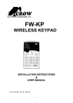
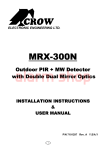
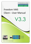
ELECTRONIC ENGINEERING LTD.
Power Wave CR16M- LCD Keypad
Users’ Operating and Programming Guide
Version 2.00
P/N 7102265 Rev. D
G.T.
Dec 2006
Contents
Introduction
4
Meet the Crow Alarm Control System
4
Typical Alarm System Configuration
4
Keypad Description
5
General Description
5
Function Keys
5
Alphanumeric Keys
5
Audible Signals
5
Indicators
6
Display
6
Summary of Functions
7
Operation
9
How to Arm the System before Exit
9
How to Arm the System when Staying Home
10
How to Arm Partitions
11
How to Bypass Zones
12
How to use Chime (If enable by Installer)
12
Generate Threat or Duress
13
How to Read System Messages
13
How to Read Trouble Messages
13
How to Display Events from Memory
14
How to Control Outputs and Devices
14
2
User Programming and Customization
14
How to Get into to User Program/Client Mode
14
How to Change or Add Codes
15
Customizing your Keypad
16
How to Add or Change Telephone Numbers
16
How to set Time and Date
17
How to operate the access control output
18
How to start Walk test Mode
18
How to Adjust Keypad Backlight Level
20
How to Adjust Buzzer Tone
20
PowerWave – LCD Keypad (Dip-Switch type) Assignment
23
PowerWave – LCD Keypad (NOT Dip-Switch type) Assignment
24
3
Introduction
Meet the Crow Alarm Control System
Thank you for choosing to protect your premises with a PowerWave of Crow Electronic
Engineering Ltd.
Power Wave of Crow Electronic Engineering Ltd. is a highly advanced, multifunction alarm
control system, designed to flawlessly manage your security system at home or at
business, protects you against burglary and supports the operation of electronic devices.
The PW has many incredible program options and additional accessories that can
enhance the standard features of the panel from simple “Home Automation” to “Radio
control” and Voice Prompted Command control”. Please ask your installer to find out more
about these powerful features.
You can phone You can phone your home to check or change the status of any output
using the keys on your phone. Arm or disarm the whole house or just one area, all with
your own voice confirming your selections.
Imagine turning on the spa before leaving work so it is hot when you get in the door. The
under-floor heating has just automatically switched on using the on board timer and you
have just opened the rollerdoor and disarmed the garage from your cell phone so the
white ware repairman can work on your washer.
The controller will support a 16 LED keypad or this, more sophisticated LCD (liquid Crystal
Display) keypad.
It also has a comprehensive alarm event memory that stores all of the controller activity
with the time and date.
Typical Alarm System Configuration
The protected premises can be divided up to 64 zones, as defined by the installation
scheme. The protected area can be grouped up to 4 separate partitions (A,B,C,D). The
system can be grouped for User ‘s convenience to separate, in a business environment,
the offices from the warehouse area, or in a private residence, the different rooms of the
home, e.g., living room, bedroom, etc.
Each zone can react differently to various events, to generate an alarm or activate a
device.
The system can be armed in two different modes:
1) Arm –the protected areas are entirely vacated
2) Stay –people and pets populate the protected areas.
The User who has access to the keypad's control features, can change the settings.
The system can be accessed via multiple keypads (each located at a different site). Up to
8 keypads can be integrated into the system. Access levels and Users’ access codes are
detailed below.
4
Keypad Description
General Description
The LCD display shows all the information required to operate the system in a friendly
manner and free of flaws. The User communicates with the alarm system via the keypad.
The Keypad displays continuous information about the status of the alarm system, and
enables the User to operate the system in different modes, change settings and program
Users' access codes.
The keypad also collects and records events to be displayed afterward on request, to
overview system activities, and to analyze system performance for diagnostics.
The keyboard is illustrated in Figure 1, and the main components are detailed below.
Function Keys
Figure 1: LCD Keypads (Large / Small)
These keys are used to arm the system, enter commands to alter system settings, or
scroll through the display.
Alphanumeric Keys
These keys are used to enter codes, change descriptions of zones, or for programming.
Audible Signals
The keypad emits signals (beeps) in response to User activities. These signals are listed
in Table 1.
5
Table 1: List of Audible Signals
Sound
Sequence
Description
Short beep
Once only
A key in the keypad has been pressed
3 short beeps
Once only
Operation carried out successfully
Long beep
Once only
Illegal operation, or wrong key pressed
Slow beeping
Through the Exit or
Entry delay time
Exit or entry delay warning when arming
the system indicates that you must exit the
protected area,
also Entry delay warning when entering
via the entry zone, to disarm the system.
Indicators
The indicators show the status of the system. The LED indicators are listed in Table 2.
Table 2: List of LED Indicators
Design.
Function
Bypass
Indicates that there are bypassed zones
Stay
Indicates that the system is armed in STAY mode
Armed
Indicates that the system is fully armed, or a partition is armed
Ready
Indicates that the system is ready to be armed
Trouble
Indicates system failure, or problem. Make note of system message
and call service
Display
The LCD window holds 2 rows of 16 characters each.
The display shows:
·
System Messages
·
Open Zones
·
System Status
·
Trouble Messages
·
Memory Events
·
Description of zones
·
Zone numbers during programming
·
Device numbers during control
6
Summary of Functions
The system's main functions are listed in Table 3.
Table 3: Summary of Functions
Function
Keys
Full
or Partition
Arm
C CODE C
Full Arm
C
ARM
Initiates full arm
Only if enabled by
installer
Disarm
during exit
C
ARM
Disarms the system
during exit delay
Only when slow
beeping is emitted
Disarm
C CODE C
C
Disarms the system
Stopping Alarms
Arms partition A or
B
Press A or B for
2 seconds to arm
relevant partition
Only if enabled by
installer
Initiates partial
alarm when the
user is home
Only if enabled by
installer
Arm
Partition
Arm Stay
ENTER
or
C
C
C
B
STAY
C
CODE
ENTER
Initiates partial
alarm when the
user is home
STAY
Disarm
Stay
C CODE C
Disarm
Stay
C
STAY
Bypass
C
BYPASS
Disarms the system
ENTER
Disarms the system
Bypasses a zone(s)
Repeats the
procedure to unbypass zones
CONTROL
Activates
emergency alert
Press
simultaneously for 2
seconds
B
Activates
emergency alert
Press
simultaneously for 2
seconds
C
Zone #
C
ENTER
Initiate
Panic
C
CHIME
Initiate
Medical
Alarm
C
CHIME
Notes
Initiates full arm
ENTER
A
C
Arm Stay
Description
+
+
7
Function
Initiate Fire
Alarm
Memory
Keys
C
C
Description
+
A
B
MEM
Activates
emergency alert
Press
simultaneously for 2
seconds
Initiates display of
events from
memory.
Displays events,
and automatically
scrolls to the next
event every 2.5 sec.
(Use arrow key to
scroll up manually)
<ENTER> cancels
memory readout
Chime
Enable/dis
able
C
Control
C
C
CHIME
CONTROL
C
Device#
ENTER
Change or
Add Users'
code
C
C
Customize
keypad
C
CONTROL
+
ARM
Increase
LCD
backlight
level
C
CONTROL
+
STAY
Decrease
LCD
backlight
level
C
CONTROL
+
BYPASS
Increase
LED
backlight
level
C
CONTROL
+
PROG
C M CODE
ENTER
Enable or disable
chime function
Holds the key for 2
sec to alternate.
Only if enabled by
installer
Activates or
deactivates outputs
and devices
Press <Control> for
2 seconds
Activates program
mode to add or
change Users'
codes
For details see
page 14
Enters Local Edit
Program Mode
Press Control and
then Arm, and hold
both simultaneously
for 2 sec
For details see
page 16
Hold <CONTROL>
and press <STAY>
repeatedly to
increase light
Hold <CONTROL>
and press
<BYPASSS >
repeatedly to
decrease light
Hold <CONTROL>
and press <MEM>
repeatedly to
increase light
MEM
8
Notes
Function
Keys
Description
Hold <CONTROL>
and press <▼>
repeatedly to
decrease light
Decrease
LED
backlight
level
C
CONTROL
+
Increase
buzzer
tone
C
CONTROL
+
A
Decrease
buzzer
tone
C
CONTROL
+
B
Note:
Notes
Hold <CONTROL>
and press <A>
repeatedly to
increase buzzer
tone
Hold <CONTROL>
and press <B >
repeatedly to lower
buzzer tone
If you started an operation incorrectly, press <ENTER> to exit and
return to the previous mode.
Operation
How to Arm the System before Exit
·
Preparing the System for Arming
Verify that the green <Ready> indicator is lit. This indicator is lit only when all zones are
closed (all doors, exits and windows are closed and motion in the protected area is
restricted or bypassed). If the green <Ready> indicator is not illuminated, the LCD
displays the open zones and descriptions.
Close open zones, or bypass them. Bypass any zone you cannot close. For details see
page 11.
Note: Bypassed zones are not protected.
·
Arming the System
PowerWave XX
DATE
TIME
When the system is ready, the LCD display shows the system type, date and time, and the
green <Ready> indicator is lit.
Before leaving premises the system has to be armed.
When the system is Ready, enter user code and then <ENTER> to arm the system.
Enter Code
****
The system prompts you to exit the protected area.
9
Areas Exiting
AThere is an exit delay prior to the system being armed. During this delay time you can
leave the premises. At the end of the procedure. the ARMED indicator lights up to
indicate that the system is armed, and the system message is displayed. (The indicators
may go out after a few seconds, depending on the installer's setting).
Areas Armed
A·
Quick Arm
When enabled by the installer, press <ARM> to arm the system.
During this delay time, a slow beeping is heard to indicate that the system is not armed yet
and reminds you to leave the protected area..
If you must disarm the system during the exit delay, press <ARM>.
·
Disarming the System
Enter User’s code and press <ENTER>.
The following system message is displayed:
Areas Disarmed
A·
Stopping Alarms
Enter User’s code and press <ENTER> to stop alarm any time.
How to Arm the System when Staying Home
·
Arming the System in Stay Mode
This type of arming is used when people are present within the protected area. At night
time, when the family is about to retire , perimeter zones are protected, but not the interior
zones. Consequently, interior movements will be ignored by the system.
When the system is Ready, press <STAY> and the system prompts you to enter user
code, and then <ENTER>.
Enter Code
****
10
·
Quick Stay
When enabled by the installer, press <STAY> to arm the system.
During exit delay you can leave the premises. If you wish to stay or that no one will enter
the protected premises, you may cancel the Entry/exit delay by pressing the <ENTER>
key. The slow beeping stops and the system is immediately armed.
At the end of the procedure, the Stay indicator lights up to indicate that the system is
armed and the system message is displayed. (The indicators may go out after a few
seconds, depending on the installer's setting).
Areas In Stay
A·
Disarming the System
Enter user’s code and press <ENTER>, or press <STAY> if enabled by installer.
The following system message is displayed.
Areas Disarmed
A-
How to Arm Partitions
The protected area can be grouped into two separate partitions (e.g. A , B and C ).. The
system can be grouped for User ‘s convenience to separate, in a business environment,
the offices from the warehouse area, or in a private residence, the different rooms of the
home, e.g., living room, bedroom, etc.
To arm partition A or B or C see Para “Arming the System”.
If enabled by the installer, to arm the partition A, press <A> for 2 seconds.
To arm partition B, press <B > for 2 seconds
The same procedure is also applicable to partition B.
Areas Exiting
-BDuring exit delay you can leave premises. At the end of the procedure the ARMED
indicator lights up to indicate that the system is armed and system message is displayed.
(The indicators may go out after a few seconds, depending on the installer's setting).
Areas Armed
-BTo disarm partition, see "Disarming the System".
Note: to arming partition with code see page 9 “How to arm the system before exit”
11
How to Bypass Zones
Bypass any zone that cannot be closed. You can bypass selected zones prior to arming.
It is also used to temporarily exclude a faulty zone from service, which requires repair.
To bypass a selected zone, press <BYPASS>, Bypass indicator lights up to indicate that
the system is in bypass mode.
Enter the zone number (e.g. 01, 05, 12 in PW16 or 1, 2, 6 in PW4/8) one or more zones.
Bypass Zones
01 05 12
Following press <ENTER>, the system displays the bypassed zones.
Zone 3 Bypass
Zone 3
While in the Bypass mode it is possible to bypass more than one zone, press <BYPASS>,
Bypass indicator lights up to indicate that the system is in bypass mode,
Add the zone number (e.g. 03) one or more zones, following press <ENTER> , the
Bypass indicator lights up to indicate zone(s) bypassed .
To un-bypass zones, press <BYPASS>, enter zone number (e.g.07,13) and press
<ENTER>.
Note: Disarming automatically un-bypasses all zones.
How to use Chime (If enable by Installer)
To disable this function, press <CHIME> for 2 seconds, as shown below.
Chime OFF
To enable this function, press <CHIME> for 2 seconds, as shown below.
Chime ON
Emergency Alerts
How to initiate Panic
Press simultaneously<CHIME>and <CONTROL> for 2 seconds.
How to initiate Medical Alarm
Press simultaneously <CHIME> and <B> for 2 seconds.
How to initiate Fire Alarm
Press simultaneously<A> and <B> for 2 seconds.
12
Generate Threat or Duress
If you are compelled to disarm the system under threat, you must enter the duress digit
before the user’s code to activate the automatic dialer. The duress digit shifts up your
usual code by one digit. If your code is 345 and 8 is your duress digit, than entering 8345
will modify your code. The modified duress code will disarm the system in a normal way,
but at the same time will activate the dialer silently to report a “duress event” without
arousing suspicion. (For details ask installer.)
How to Read System Messages
Any system failure that may that may occur, is indicated by system messages. System
messages are automatically displayed and are listed in Table 4. Read messages and call
for service.
Table 4: System Messages
Message
Description/Action
Battery Low
The backup battery is low (charger or battery failure)
Main Failure
The main power is disconnected, or caused by power
outage.
Telephone Line Failure
The line is disconnected
Radio Device Battery Low
Replace battery of the particular device
Supervise Detector
Failure
Radio detector failed to communicate
Zone Inactivity Time-out
No movement detected during expected time in this zone
Dialer Kiss-off Failure
Communication fail
How to Read Trouble Messages
Any failure or -abnormal events that may occur are indicated by trouble messages, and
the Trouble indicator is lit. Press <MEM> to read out messages and other events stored in
memory. Trouble messages are listed in Table 5.
Table 5: Trouble Messages
Message
Description/Action
Zone Tamper
The tamper of a particular zone
System Tamper
Main cabinet open
Pendant Panic
Panic alarm initiated via radio pendant
Panic
Panic alarm initiated via keyboard
Fire
Fire alarm initiated via keyboard
Medical
Medical alarm initiated via keyboard
Duress code used
Duress digit pressed by one of the users, under threat
13
How to Display Events from Memory
The system memory stores the last events. Press <MEM> to display list of events. The
system will display the last event and automatically scroll to the next one every 2.5
seconds, and a beep is emitted. Use the arrow keys to scroll up manually. Each entry
shows the type of event, date and time. Wait until all messages are displayed, or press
<ENTER> to cancel memory readout.
If the message exceeds 16 characters, use the right arrow to read the message.
How to Control Outputs and Devices
The keypad enables control of external devices, such as an air-conditioner or heater. To
activate or halt a device, press <CONTROL> for 2 seconds and the number of the
device. Up to 8 different devices can be controlled via the keypad.
Control Mode
---4----When you enter control mode the system prompts you to enter device # and then
<ENTER> to activate or deactivate the selected device.
User Programming and Customization
How to Get into to User Program/Client Mode
There are 2 levels of program mode, CLIENT mode and INSTALLER mode. Normally the
installer will give you access to the CLIENT mode so you can add, delete, or change the
user codes. If you request it your installer can provide you with access to the INSTALLER
mode as well. To get into CLIENT mode provided the system is NOT armed Press
<PROGRAM> enter Master code and <ENTER>.
If you get a single long beep at this point , it means your code cannot access Program
mode.
·
How to exit program mode
To exit out of program mode press <PROGRAM> and <ENTER>.
The LCD display shows the system type, date and time.
PowerWave XX
DATE
14
TIME
How to Change or Add Codes
About Master code and User code
The factory default master code (123) is intended as a preliminary control of the alarm
system. After PowerWave is installed and put into service, the code can be changed to
any code known to the Master user. The Master user can define up to 99 user codes. To
limit access rights, the holder of the Master code can ask the installer to define several
User profiles.
Access rights are listed below:
-
User code has Area A and/or B or C permission
-
User code can arm and/or disarm arm an area
-
User code can arm and/or disarm arm an area in Stay mode
-
User code can change its code
-
User code can change user’s code
-
User code can Operate control Functions
-
User code can change dialer telephone numbers
-
User code can alter the real time clock
-
User can answer an incoming call and start up/down load
-
User can allow access to installer program mode from client mode.
-
Initiate Walk-test mode.
How to Change Master Code
Press <PROG> enter Master code and <ENTER>. The display will show “Client Mode”.
Client Mode
Press <PROG> and 1 to change Master code. Use the numeric keyboard to enter your
new Master code. The code can hold any combination of 1 to 6 digits. It is recommended
using a multi-digit code. . Press <ENTER> to save your new code. To proceed to the next
user code, Press <MEM>. Press <PROG> and <ENTER> exit Client Program mode.
How to Add or Change User Code
In client mode, press <PROG> and the User number (2 to 100) to add or change the
code. Use the numeric keyboard to enter the new code. The code can hold any
combination of 1 to 6 digits. Press <ENTER> to save your new code.
User 3 Code
56789
Repeat the procedure for all users or use arrow (MEM) key to advance to next user.
Press <PROG> and <ENTER> to exit Local Program mode.
15
How to Delete User Code
In client mode, press <PROG> and the User number (2 to 100) you intend to delete.
The display shows the code.
User 8 Code
8765
Press <CONTROL> and<0> simultaneously to delete User code. Press <ENTER> to save
the change.
Press <PROG> and <ENTER> exit Client Program mode.
Customizing your Keypad
Local Edit Program mode assists the user to customize descriptions, adjust keypad light
and buzzer tone.
How to Enter Local Edit Program Mode to Describe Zones
To enter this mode, press and hold <CONTROL> and at the same time press <ARM>
for 2 seconds. The display will show “Local Mode kb #”. From hereon, you can change
the numeric description of a zone to a textual description.
Press <PROG> <1> to change the description of Zone 1. For example, Use the arrow
keys to move the cursor forward or backward on the display. Press the corresponding key
to replace the current digit. Each key represents 3 different characters. The first
character will be shown at the first press, etc. Press <MEM> to change from
uppercase to lowercase and visa-a-versa.
Zone 1
Bedroom
<A..Z>
During the programming of text for all of the addresses 1-8,998,999 you can also use the
<A> button to return back to last saved text and you can use <B> button to return back to
the default text.
Press <ENTER> to save textual description.
For more zones, press <PROG>, followed by Zone # to continue textual description.
The functions of the alpha-numeric keys are listed in Table 6 below.
16
Table 6: Summery of Alphanumeric Keys
Button #
1st Press
2nd Press
3rd Press
4th Press
1
* (‘)
# (<)
= (>)
1
2
A (a)
B (b)
C (c)
2
3
D (d)
E (E)
F (F)
3
4
G (g)
H (h)
I (i)
4
5
J (j)
K (k)
L (l)
5
6
M (m)
N (n)
O (o)
6
7
P (p)
Q (q)
R (r)
7
8
S (s)
T (t)
U (u)
8
9
V (v)
W (w)
X (x)
9
0
space
Y (y)
Z (z)
0
How to Add or Change Telephone Numbers
Depending on the type of panel you have, you can program up to 6 phone numbers, each
with a total of 16 digits. Your panel can be programmed to dial all or any of these
telephone numbers depending on the event which has occurred.
(In PW16 The six phone #’s are at program address 331 through to 336).
(In PW4/8 The four phone #’s are at program address 501 through to 504).
(In PW64 (Wireless) The six phone #’s are at program address 691 through to 696).
(In PW64EX (HardWired). The six phone #’s are at program address 831 through to 836).
While in CLIENT mode, key in the following sequence <PROGRAM> <XXX (where XXX
is the Address location for telephone number 1, according to the model of PW alarm
you have - see above)> <ENTER>
The existing number will be flashed back at the Keypad, type-in <NEW TELEPHONE #>
<ENTER> The new numbers will be flashed back to confirm acceptance.
At any time, you can review either the current or the next telephone number. To do this,
press the <PROGRAM> button followed by the Address location for telephone number
you want to view, then <ENTER> .
Note-1: In PW4/8 Address 501 = PH # 1, 502 = PH# 2 to 504 = PH# 4.
Note-2: In PW16 Address 331 = PH # 1, 332 = PH# 2 to 336 = PH# 6..
Note-3: In PW64 (Wireless) Address 691 = PH # 1, 692 = PH# 2 to 696 = PH# 6.
Note-4: In PW64EX (HardWired) Address 831 = PH # 1, 832 = PH# 2 to 836 = PH# 6.
17
How to set Time and Date
The alarm system has an internal clock that may be used to automatically Arm or Disarm
the alarm or turn Outputs On or off. It is also used to identify when events occurred in
memory via the LCD keypad. Should you need to change the Time & Date it must be done
from CLIENT mode.
To change the Time & Date press
(Sun = Day-1 / Sat = Day-7)
In PW16 - Press <PROGRAM> <823> <ENTER> <1-7> <ENTER>
In PW4/8 - Press <PROGRAM> <403> <ENTER> <1-7> <ENTER>
In PW64 (Wireless) - Press <PROGRAM> <678> <ENTER> <1-7> <ENTER>
In PW64EX (HardWired) - Press <PROGRAM> <818> <ENTER> <1-7> <ENTER>
Where 1-7 = the current day (1=Sun, 2 = Mon to 7 = Sat)
In PW16 - Press <PROGRAM> <824> <ENTER> <HHMM> <ENTER>
In PW4/8 - Press <PROGRAM> <401> <ENTER> <HHMM> <ENTER>
In PW64 (Wireless) - Press <PROGRAM> <679> <ENTER> <HHMM> <ENTER>
In PW64EX (HardWired) - Press <PROGRAM> <819> <ENTER> <HHMM> <ENTER>
Where HH = Hour in 24 Hour Format and MM = Minutes
In PW16 - Press <PROGRAM> <825> <ENTER> <1-31> <ENTER>
In PW4/8 - Press <PROGRAM> <405> <ENTER> <1-31> <ENTER>
In PW64 (Wireless) - Press <PROGRAM> <680> <ENTER> <1-31> <ENTER>
In PW64EX (HardWired) - Press <PROGRAM> <820> <ENTER> <1-31> <ENTER>
Where 1-31 = the current date
In PW16 - Press <PROGRAM> <826> <ENTER> <1-12> <ENTER>
In PW4/8 - Press <PROGRAM> <406> <ENTER> <1-12> <ENTER>
In PW64 (Wireless) - Press <PROGRAM> <681> <ENTER> <1-12> <ENTER>
In PW64EX (HardWired) - Press <PROGRAM> <821> <ENTER> <1-12> <ENTER>
Where 1-12 = the current month
In PW16 - Press <PROGRAM> <827> <ENTER> <YY> <ENTER>
In PW4/8 - Press <PROGRAM> <407> <ENTER> <YY> <ENTER>
In PW64 (Wireless) - Press <PROGRAM> <682> <ENTER> <YY> <ENTER>
In PW64EX (HardWired) - Press <PROGRAM> <822> <ENTER> <YY> <ENTER>
Where YY = current year, e.g. 02=2002
18
How to operate the access control output
If the alarm system has been set up to allow control of an electric door lock, you can
activate the door release function as follows;
Press <CONTROL> or Press <CONTROL> enter CODE then <ENTER>
The Control LED will lights up while the lock is active and turn off as soon as power is
removed from the lock.
The Access Control function can either be a single button operation or restricted to
requiring a valid User code entry. Both options are shown above. Please consult your
installer as to what option may be programmed.
How to start Walk test Mode
In PW16 (ver:6.20+), PW64 (Wireless) and PW64EX (HardWired) - While in CLIENT
mode, a User with the proper authority can start walk-test mode. This special mode
latches the alarm signals from detectors at the keypad initiating the test so that one person
can trigger every detector connected to the alarm then return to the keypad to verify
operation. On terminating Walk-test mode the test results are put into the memory buffer
so they can be viewed at a later time. Must be in CLIENT mode to start Walk-test mode.
In PW16 (ver:6.20+) - Press <PROGRAM> <836> <ENTER>
In PW64 (Wireless) - Press <PROGRAM> <956> <ENTER>
In PW64EX (HardWired/Expandable) - Press <PROGRAM> <1096> <ENTER>
The keypad buzzer will beep at 1-second intervals
Next, trigger every detector connected to the panel then return to the keypad and all of the
zones that were triggered will be displayed at the keypad.
To terminate Walk-test mode, press <ENTER>
The keypad will stop beeping and automatically exit CLIENT mode.
How to Answer an in-coming call
In the PW panels - From time to time, your installer may need to access the alarm from a
remote PC to make changes to your programming. For security reasons, they may have
configured the alarm so that an authorized person on-site is required to make the alarm
system answer the in-coming call. This option is only available in CLIENT mode.
To answer an In-coming Call (from CLIENT mode);
In PW16 (ver:6.20+) - Press <PROGRAM> <835> <ENTER>
In PW64 (Wireless) - Press <PROGRAM> <955> <ENTER>
In PW64EX (HardWired/Expandable) - Press <PROGRAM> <1095> <ENTER>
This feature is Not available in the PW8 control panel.
Provided the line connected to the alarm was ringing at the time, the panel will now
answer the call and allow a remote PC connection.
19
How to Program System Description
While in Local Edit Program Mode Press <PROG> <999> and then <ENTER>. You may
enter any name for your system (up to 16 characters).
Name
<A..Z>
Johnson Family
To save changes, press <ENTER>.
How to Program Area Description
While in Local Edit Program Mode Press <PROG> <998>, and then <ENTER>. You may
edit any character, one per each area.
Areas
<A..Z>
ABCDEFGHIJKLMNOP
To save changes press <ENTER>.
To update and transfer programmed textual information from one LDC keypad to another,
press <CHIME> for 2 seconds.
To exit Local Edit Program Mode and return to Idle Mode, press <PROG> and then
<ENTER>.
How to Adjust Keypad Backlight Level
The User can adjust the backlight of the keys and LCD display in 16 steps, from Fully
illuminated to Off.
To increase LCD backlight, hold <CONTROL> and press <STAY> repeatedly until the
light is increased to its maximum.
To decrease LCD backlight, hold <CONTROL> and press <BYPASS> repeatedly until the
light goes off.
To increase keyboard backlight, hold <CONTROL> and press <MEM> repeatedly until the
light is increased to its maximum.
To decrease keyboard backlight, hold <CONTROL> and press <▼> repeatedly until the
light goes off.
How to Adjust Buzzer Tone
The User can adjust the volume of the buzzer tone can be adjusted, in 16 steps, from fully
On to Off.
To increase the volume, hold <CONTROL> and press <A> repeatedly until it is increased
to its maximum.
To decrease the volume, hold <CONTROL> and press <B> repeatedly until it is
decreased to off.
20
Warranty
CROW LIMITED WARRANTY
(Crow) warrants this product to be free from defects in materials and
workmanship under normal use and service for a period of one year from the
last day of the week and year whose numbers are printed on the printed circuit
board inside his product.
Crow’s obligation is limited to repairing or replacing this product, at its option,
free of charge for materials or labor, if it is proved to be defective in materials or
workmanship under normal use and service. Crow shall have no obligation
under this Limited Warranty or otherwise if the product is altered or improperly
repaired or serviced by anyone other then Crow.
There are no warranties, expressed or implied, of merchantability or fitness for a
particular purpose or otherwise, which extend beyond the description on the
face hereof. In no case shall Crow be liable to anyone for any consequential or
incidental damages for breach of this or any other warranty, expressed or
implied, or upon any other basis of liability whatsoever, even if the loss or
damage is caused by Crow’s own negligence or fault.
Crow does not represent that this product can not be compromised or
circumvented; that this product will prevent any person injury or property loss or
damage by burglary, robbery, fire or otherwise; or that this product will in all
cases provide adequate warning or protection. Purchaser understands that a
properly installed and maintained product can only reduce the risk of burglary,
robbery or other events occurring without providing an alarm, but it is not
insurance or a guarantee that such will not occur or that there will be no
personal injury or property loss or damage as a result. Consequently, Crow shall
have no liability for any personal injury, property damage or any other loss
based on claim that this product failed to give any warning. However, if Crow is
held liable, whether directly or indirectly, for any loss or damage arising under
this limited warranty or otherwise, regardless of cause or origin, Crow’s
maximum liability shall not in any case exceed the purchase price of this
product, which shall be the complete and exclusive remedy against Crow.
21
Use the following form to record your changes and customizations.
User #
1
2
3
4
5
6
7
8
9
10
11
12
13
14
15
16
17
18
19
20
21
22
23
24
25
26
27
28
29
30
Name
Output # Device
Designation
1
2
3
4
5
6
7
8
User #
31
32
33
34
35
36
37
38
39
40
41
42
43
44
45
46
47
48
49
50
Name (Cont)
22
Zone
#
1
2
3
4
5
6
7
8
9
10
11
12
13
14
15
16
Zone Name
PowerWave – LCD Keypad (Addressing & Panel Type) Assignment
This sections is for Addressing LCD Keypads with Dip-Switches.
*** Note: Refer to Next Section for LCD Keypads that do Not have
Dip-Switches. ***
Each of the 8 possible LCD keypads that can be connected to your PW control Panel,
must be set to the suitable type of control panel and addressed individually to avoid Buss
conflicts.
To assign the KEYPAD Address
Keypad #1
Keypad #2
Keypad #3
Keypad #4
Keypad #5
Keypad #6
Keypad #7
Keypad #8
Switch 1
Switch 2
Switch 3
OFF
ON
OFF
ON
OFF
ON
OFF
ON
OFF
OFF
ON
ON
OFF
OFF
ON
ON
OFF
OFF
OFF
OFF
ON
ON
ON
ON
To assign type of PowerWave Control Panel
PW-4
PW-8
PW-16
PW-64 (Ver1.01)
PW-64 (Ver1.04)
Switch 5
Switch 6
Switch 7
OFF
ON
OFF
ON
OFF
OFF
OFF
ON
ON
OFF
OFF
OFF
OFF
ON
OFF
To set the Keypad tamper mode
Switch 8
Disable Keypad Tamper
ON
Enable Keypad Tamper
OFF
NOTE: Until further notice, Switch 8 MUST be left in the ON position (Tamper Disabled)
i.e.: Keypad Tamper Mode is reserved for future use.
23
This sections is for Addressing LCD Keypads that do Not have Dip-Switches.
Each of the 8 possible LCD keypads that can be connected to your PW control Panel,
must be set to the suitable type of control panel and addressed individually to avoid Buss
conflicts.
For LCD Keypads that do Not have Dip-Switches, the function of assigning both the
Keypad Address and the Panel Type is done in what is called ‘Local Mode’. To enter
‘Local Mode’, you must;
1)- Connect the LCD Keypad to the Control Panel and apply Power to the
Control Panel (which will also Power-Up the LCD Keypad).
2)- On the LCD Keypad, press and Hold down the “CONTROL” button and
within 1.5 seconds, also press and Hold down the “ARM” button (almost like
pressing and holding down both buttons simultaneously). The Keypad will
display ‘LOCAL MODE KP1’ on the LCD screen. You are now in ‘Local Mode’
and can enter the following programming addresses.
- To change the Keypad Address, press;
<PROG> 900 <ENTER>.
The display will now show the current Keypad Address, simply press a number
key from 1-8 then <ENTER>. This will now be the new address.
- To change the Keypad Tamper press;
<PROG> 901 <ENTER>.
The display will now show the current setting, simply press any number key from
0-9.
This will alternate the settings between Enable / Disable.
Press <ENTER> to confirm selection.
NOTE: Until further notice, the Keypad Tamper mode should be Disabled.
i.e.: Keypad Tamper Mode is reserved for future use.
- To change the Panel Type, press;
<PROG> 902 <ENTER>.
The display will now show the current panel type setting, simply press any
number key from 1-5. The display will then show the new panel type.
Press <ENTER> to confirm selection.
The Panel Types are;
1 = ELITE 8D/LITE (= Default setting) - This is the same as PW8 & PW8-LITE.
2 = ELITE 16D - This is the same as PW16 Ver: 6.20 to 6.32+ Control Panel.
3 = PW64a - This is the Older Ver: 1.01 Wireless 64Zn Control Panel.
4 = PW64b - This is the Current Ver: 1.04+ Wireless 64Zn Control Panel.
5 = ELITE 64 - This is the Current PW64EX Ver: 2.01+ Hardwired
64Zn (Expandable) Control Panel.
24
Your Crow Alarm System can be configures and programmed to operate in many different
ways. All of the User Functions that can be performed and operated by this LCD Keypad,
are listed in this Users’ & Programming Guide.
If some functions described in this Users’ & Programming Guide are not operating, it
indicates that your systems installer may Not have enabled that feature or function.
If you have any difficulty in performing a function mentioned in this Users’ & Programming
Guide, and you have thoroughly read and understood this Users’ & Programming Guide,
we suggest that your first point of contact for assistance should be the person (or
company) that originally installed your Crow alarm system. Their details may be found on
Security ‘Warning Stickers that could be located on Windows, the External Siren box, the
enclosure (or box) of your actual system (usually in a cupboard), etc.
Your Crow Systems installer would have the best knowledge of how your particular
system is configured, and therefore would be the best person to offer advice and
assistance.
If you are unable to contact the person (or company) that originally installed your Crow
alarm system, please contact us at Crow (details below) and we will provide you with the
name of a Crow products distributor located closest to you. You may then contact the
Crow products distributor who can provide you with name(s) of Crow systems installers in
your area for you to contact for assistance.
Please note that we (Crow Electronic
Engineering) are the Manufacturers & Suppliers Only of the Crow brand of products and
we (Crow Electronic Engineering) do Not have installation or service technicians that
perform site visits.
www.crowaust.com.au
[email protected]
25
Dec 2006
26