1
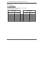
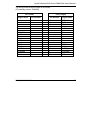
Insyde Software BIOS for the DIMM-520 User's Manual Insyde Software BIOS for the DIMM-520, User's Manual Copyright 2002: FS FORTH-SYSTEME GmbH Postfach 1103, D-79200 Breisach a. Rh., Germany Release of Document: Filename: Author: BIOS Version July 04, 2002 BIOS_DIMM520_a5.DOC Pedro Perez de Heredia 1.x All rights reserved. No part of this document may be copied or reproduced in any form or by any means without the prior written consent of FS FORTH-SYSTEME GmbH. 2 BIOS_DIMM520.DOC Insyde Software BIOS for the DIMM-520, User's Manual Contents 1. General ...............................................................................................................4 1.1. Features ...................................................................................................4 2. BIOS Installation .................................................................................................5 2.1. BIOS Flashing Utility ................................................................................5 2.1.1. Programming flash devices .........................................................6 2.1.2. Reading flash devices..................................................................7 2.1.3. Display flash drives information ...................................................8 2.2. JTAG-Booster for AMD ElanSC520.........................................................8 3. Chipset Details ...................................................................................................9 3.1. Memory Map.............................................................................................9 3.2. Interrupt Map ..........................................................................................10 3.3. DMA-Map................................................................................................11 3.4. PAR Windows ........................................................................................12 3.4.4. PAR Mapping with ISA VGA......................................................13 4. Remote Features..............................................................................................14 4.1. The Remote Server REMHOST.EXE ....................................................15 4.2. Cable Definition......................................................................................16 4.3. Restrictions ............................................................................................18 5. User-defined CMOS Defaults...........................................................................19 6. Integrated Flash-File-System ...........................................................................20 7. Quick Power-Up ...............................................................................................21 8. Video Card Emulation.......................................................................................21 BIOS_DIMM520.DOC 3 Insyde Software BIOS for the DIMM-520, User's Manual 1. General This BIOS was developed to support the features of the FS FORTH-SYSTEME DIMM-520 module. It has been designed to provide maximum PC/AT compatibility. It has been tested thoroughly with testing environments from the PCISIG and Microsoft´s System Confidence Test. 1.1. Features • • • • • • • • • • • • • • • • • • • 4 Dynamic SDRAM detection Configurable L1-cache Master/Slave Harddrives Floppy Keyboard ISA/PCI Video Parallel port in standard, bidirectional or epp mode 2 configurable COM ports Numerical coprocessor Plug and Play BIOS 2.1 PCI-Specification Compliant System Configuration Utility Remote Features (Video, Keyboard, Floppy) CMOS-Defaults from EEPROM Virus Protection Password Protection for Setup and Boot Flash Disk Support Card Boot (optional) Integrated ROM Debugger (optional) BIOS_DIMM520.DOC Insyde Software BIOS for the DIMM-520, User's Manual 2. BIOS Installation FORTH-SYSTEME provides two methods to program the BIOS into the flash, the utility BFLASH.EXE for BIOS updates under DOS and the JTAG-Booster for initial flash programming. Since the flash device on the DIMM-520 is larger than 1MB, the BIOS needs to be programmed into two different regions: - 256K BIOS at address 0C0000h The upper 4K of the BIOS image at the top of the flash 2.1. BIOS Flashing Utility For updating the BIOS under DOS, we have added the flashing utility BFLASH.EXE to this kit. When starting BFLASH without parameters, the following help screen with all possible functions and options is displayed: BFLASH --- BIOS programming utility for the DIMM-520 Copyright (C) FS FORTH-SYSTEME GmbH, Breisach Version 2.00 of 01/18/2001 Usage: BFLASH /function [filename] [/option_1] [/option_n] Supported functions: /P : Program file into flash drive /R : Read from flash drive into file /I : Display flash drives information Supported options: /UNIT= : Select flash drive /ERASEALL : Erase all flash chips /NOERASE : Do not erase before programming /TOP : Program file on top of flash /O= : Offset within the flash disk (hex) /L= : Length of image file /FO= : File offset (hex) BIOS_DIMM520.DOC 5 Insyde Software BIOS for the DIMM-520, User's Manual Before running this utility, make sure that no expanded memory manager such as EMM386.EXE is installed. Do not switch off or reset the SC520-board while BFLASH is programming your flash. 2.1.1. Programming flash devices Usage: BFLASH /P filename [options] The specified file is programmed into the flash memory. The type of flash device is automatically detected by the software. Options: /UNIT=x Selects a flash disk unit, if more than one exists. On the DIMM-520, there is only one flash unit, so this switch is not required. Default: /UNIT=0 /O=xxxx The programming starts at an offset of xxxx. If the offset is negative, the offset specifies an address relative to the end of the flash disk. Default: /O=0 /TOP The programming starts at the end of the flash unit minus the size of the file image. /FO=xxxx This switch specifies an offset into the image file. The first xxxx bytes of the file are skipped and not programmed to the flash. Default: /FO=0 /L=xxxx The number of bytes to program may be limitited by the /L-option (length). Without this option, the whole file will be programmed (starting from /FO) Default: /L=file size /ERASEALL 6 BIOS_DIMM520.DOC Insyde Software BIOS for the DIMM-520, User's Manual Erase the whole flash unit. Without this option, only those blocks will be erased where new data should be written to. /NOERASE This option prevents the flash from being erased. Examples: BFLASH /P BIOS.ROM /O=C0000 /ERASEALL This programs the 256K BIOS image to the address range C0000..FFFFF. The entire flash unit is erased. BFLASH /P BIOS.ROM /FO=3F000 /O=-1000 This programs the upper 4K of the BIOS image to the top of flash. The topmost flash block will be erased before programming. 2.1.2. Reading flash devices Usage: BFLASH /R filename [options] The contents of the flash memory is read and written to a file. Options: /UNIT=x Selects a flash disk unit, if more than one exists. On the DIMM-520, there is only one flash unit, so this switch is not required. Default: /UNIT=0 /O=xxxx Reading starts at an offset of xxxx. If the offset is negative, the offset specifies an address relative to the end of the flash disk. Default: /O=0 /L=xxxx The number of bytes to read may be limitited by the /L-option (length). Without this option, the whole flash disk will be read (starting from /O=) Default: /L=size of flash disk BIOS_DIMM520.DOC 7 Insyde Software BIOS for the DIMM-520, User's Manual Examples: BFLASH /R BIOS.IMG /O=C0000 /L=40000 This example reads the address range C0000..FFFFF into the file BIOS.IMG. 2.1.3. Display flash drives information Usage: BFLASH /I BFLASH displays the total size and erase zone size of all flash drives available. 2.2. JTAG-Booster for AMD ElanSC520 The BIOS can also be replaced by an external JTAG-programmer. The JTAGBooster does not require system software running on your target, so this can be your last rescue, if the BIOS got accidently destroyed. Please refer to the manual “JTAG-Booster for AMD ElanSC520” for detailed information. To program the BIOS on the DIMM-520 using JTAGEL5.EXE, the following commands must be started: JTAGEL5 /P BIOS.ROM /O=C0000 /VERIFY /NODUMP /LPT-BASE=378 /MBUS JTAGEL5 /P BIOS.ROM /TOP /L=1000 /VERIFY /NODUMP /LPT-BASE=378 /MBUS 8 BIOS_DIMM520.DOC Insyde Software BIOS for the DIMM-520, User's Manual 3. Chipset Details 3.1. Memory Map 000000..9FFFFh Low Memory Area A0000h..BFFFFh Video Adapter Space (PCI or ISA) C0000h..DFFFFh Adapter Space for BIOS extensions E0000h..EEFFFh System BIOS extensions EF000h..EFFFFh RealMode MMCR F0000h..FFFFFh System BIOS 100000h.. High Memory Area 8000000h..8FFFFFFFFh On-board flash FFFEF000h..FFFEFFFFh ProtectedMode MMCR FFFFF000h..FFFFFFFFh BootVector BIOS ROM The adapter space at C0000h..DFFFFh is used for PCI BIOS extensions and ISA bus. The BIOS will automatically provide shadow RAM for extensions and maps the remaining space for ISA bus. The ISA bus memory hole is an important feature required for ISA devices, that map ROM or RAM into the adapter space. Examples for this are ISA network cards or PCMCIA controllers. BIOS extensions of PCI devices will always be copied to shadow RAM by the BIOS. They will be copied one after another behind the VGA BIOS. ISA cards that require ISA memory space should be configured to use addresses right below E0000h in order to prevent conflicts with PCI shadow ROM’s. BIOS_DIMM520.DOC 9 Insyde Software BIOS for the DIMM-520, User's Manual 3.2. Interrupt Map For AT-compatibility we do not use the second slave interrupt controller of the AMD ÉlanSC520. Nevertheless, the customer is free to map the second slave interrupt controller into the system and use the additional 8 interrupt lines. Note that using these interrupts require special interrupt service routines. IRQ Mapping Register Function 0 PIT0MAP Timer Ticker 1 GP1IMAP Keyboard 2 - Slave Interrupt Controller 1 GP3IMAP Serial Port 2F8 or ISA Bus IRQ3 GP4IMAP Serial Port 3F8 or ISA Bus IRQ4 5 GP5IMAP Serial Port 3E8 or ISA Bus IRQ5 6 GP6IMAP Floppy 7 GP7IMAP Serial Port 2E8 or ISA Bus IRQ7 8 RTCMAP Real Time Clock 9 GP9IMAP ISA Bus IRQ9 10 GP8IMAP ISA Bus IRQ10 11 GP0IMAP ISA Bus IRQ11 12 GP2IMAP PS/2 Mouse 13 FERRMAP Floating Point Error 14 GP10IMAP Hard Disk 3 4 15 10 Not mapped BIOS_DIMM520.DOC Insyde Software BIOS for the DIMM-520, User's Manual The ISA bus interrupts 7, 9, 10, 11 and 15 may also be used for PCI devices. The BIOS scans the PCI bus for PCI devices and examines their configuration space. If devices are requesting interrupts, the BIOS maps interrupt resources to the PCI bus and disables the corresponding ISA interrupts. So PCI will always have precedence over ISA interrupts. Eventhough PCI devices may request more than one interrupt, the PCI bus will only use up to four different interrupts INTA..D. Interrupts on the PCI bus are shareable. A BIOS user can assign specific interrupts to INTA..D in setup or let the BIOS automatically decide which interrupts are free for PCI. 3.3. DMA-Map DMA 0 ISA (GPDRQ0) DMA 1 unused Not connected on DIMM DMA 2 Floppy (GPDRQ2) DMA 3 unused Not connected on DIMM DMA 4 reserved for slave cascading DMA 5 ISA Bus (GPDRQ1) DMA 6 unused Not connected on DIMM DMA 7 ISA Bus (GPDRQ3) BIOS_DIMM520.DOC 11 Insyde Software BIOS for the DIMM-520, User's Manual 3.4. PAR Windows The PAR windows are used to build a PC/AT compatible environment. Without appropriate PAR-Windows, the AMD ÉlanSC520 maps DRAM continuously into the address space. All memory cycles behind the DRAM are treated as PCI memory cycles. A PC/AT compatible environment requires 640 KB low memory, 128 kByte at A0000h for video, 128 kByte at C0000h for ISA adapter space and 128 kByte at E0000h for the system BIOS. I/O below 400h can be configured for either PCI or ISA. All I/O accesses above 400h are treated as PCI cycles. To support a mixture between both bus types, some PAR windows must be used. Typically PCI I/O is mapped into higher I/O ranges. The BIOS is responsible to map I/O requests from PCI devices conflict free into the I/O space. The only exception for this are PCI VGA cards. They can use fixed I/O addresses for backward compatibility to ISA devices (94, 102, 3B0..3DF, 46E8). PAR windows can be configured to map PCI memory, but not PCI I/O. Once the I/O below 400h is configured for ISA, there is no possibility to access PCI I/O. The InsydeSoftware BIOS looks on the ISA bus if a VGA card is available. If not, it always maps the I/O space below 400h to PCI in order to support PCI VGA cards. All remaining I/O space below 400h will be made accessible to ISA I/O by using several PAR windows. PAR windows may also be used for chip selects to external devices. To support such an I/O space, you can simply program another PAR window which overlaps the existing I/O windows below 400h. Overlapping PAR windows is allowed, the lower PAR window will always have priority to the higher PAR windows. The DIMM-520 has no PCI VGA-controller on-board and does not provide the ability to connect further PCI devices. Therefore, the BIOS always assumes a setting for ISA VGA cards. Note, that all PAR-windows used to map ISA I/O or memory are routed to the unused general purpose chipselect GPCS5. The I/O windows above 400h are mainly used to support PNPISA cards. 12 BIOS_DIMM520.DOC Insyde Software BIOS for the DIMM-520, User's Manual 3.4.4. PAR Mapping with ISA VGA Wind. Type Address Function PAR0 Memory A0000..BFFFF r/w, ISA Video Memory PAR1 Memory 8000000.. 8FFFFFF Flash-chip at BOOTCS PAR2 I/O tbd GPCS0 (tbd) PAR3 I/O 1F0..1F7 Harddisk at GPCS6 PAR4 I/O 3F6..3F7 Harddisk at GPCS7 PAR5 I/O 400..5FF ISA devices PAR6 I/O 600..7FF ISA devices (includes 2. Port80 on CDP) PAR7 I/O 800..9FF ISA devices PAR8 I/O A00..BFF ISA devices (includes A79 for PNPISA) PAR9 I/O E00..FFF ISA devices PAR10 I/O C00..CF7 ISA devices PAR11 I/O D00..DFF ISA devices PAR12 I/O 46E8..46E8 ISA VGA Enable Register PAR13 Memory C0000.. write-protected BIOS extensions PAR14 Memory ..DFFFF ISA adapter space PAR15 Memory E0000..FFFFF BIOS write-protection BIOS_DIMM520.DOC 13 Insyde Software BIOS for the DIMM-520, User's Manual 4. Remote Features FS FORTH-SYSTEME has added its remote package "Embedded Support Kit" to the AMD ÉlanSC520 BIOS. The Embedded Support Kit allows you to control your target machine from a host computer using either a serial or parallel nullmodem cable. This is accomplished by transferring all INT10h (video) and INT16h (keyboard) requests to the host machine, executing the command there, and finally returning the results back to the target system. The target system seems to behave just like it would use its own VGA card and keyboard, but in fact it uses the resources of the host computer. Additionally, the target can access the floppy drive of your host PC. These features are of great value when you bring up your own board for the first time. In embedded systems, typical PC components are often left away to save costs. A standard BIOS typically would stop and warn the user that devices are missing. The BIOS has been modified to go on even if there is no keyboard or display adapter. With the “Embedded Support Kit”, users can almost work with such machines like they are used to on a standard PC. The BIOS contains support for both serial and parallel transmission. During power-up, it automatically detects, if a REMHOST-connection can be established on the serial or parallel port. 14 BIOS_DIMM520.DOC Insyde Software BIOS for the DIMM-520, User's Manual 4.1. The Remote Server REMHOST.EXE The utility REMHOST is started on the host computer. It listens on the serial or parallel port for incoming target requests, executes the commands and sends the output values back. The user can decide on the host machine in a configuration file, which devices the target system should redirect. By default, the target assumes to redirect video and keyboard services. The following options are available in the configuration file REMHOST.INI: PORT=1 LPT // COM or LPT port number // use parallel port for transmission // comment this for serial port. FLOPPY // enable remote floppy FLOPPY=ROMDOS.IMG // use a floppy disk image WRPROT // simulate write-protection for remote drives NOKEYB // disable remote keyboard NOVIDEO // disable remote video DUALVIDEO // use target display and remote video simultaneously Within the configuration file, you can add comments with “//”. Instead of using a real floppy drive, you can also generate image files of floppy disks. Access to these image files are much faster than to real floppy disks. Additionally, the image files can be write-protected. So you can build up virtual floppy drives to initially set up the target’s file system or to start test tools during production. Floppy disk images can be produced with Type “FDIMAGE /H” to get a list of available options. the utility FDIMAGE. When video redirection is enabled (option NOVIDEO not active), the BIOS will skip the initialization of both ISA and PCI VGA cards. The BIOS thereby comes up much quicker. Using the keyword DUALVIDEO will enable possible VGA cards as well and display video output on both the real video card and on the remote machine. This allows hardware engineers to debug vga controller problems. The BIOS will not warn for missing keyboards as soon as remote keyboard is enabled. BIOS_DIMM520.DOC 15 Insyde Software BIOS for the DIMM-520, User's Manual You can leave REMHOST by pressing the left SHIFT and STRG keys simultaneously. 4.2. Cable Definition The wiring of the serial null-modem cable is as follows: (FS ordering number: TK00053) PC1 (Host) 16 PC2 (Target) Signal Name Pin Number DCD RxD TxD DTR GND DSR RTS, CTS 1 2 3 4 5 6 7,8 − − − − − − − Pin Number Signal Name 7,8 3 2 6 5 4 1 RTS, CTS TxD RxD DSR GND DTR DCD BIOS_DIMM520.DOC Insyde Software BIOS for the DIMM-520, User's Manual The wiring of the DOS/Link-Cable is as follows: (FS ordering number: TK00925) PC1 (Host) Signal Name PC2 (Target) Pin Number Pin Number Signal Name D0 D1 D2 D3 D4 2 3 4 5 6 − − − − − 15 13 12 10 11 ERROR# SLCT PE ACK# BUSY ERROR# SLCT PE ACK# BUSY 15 13 12 10 11 − − − − − 2 3 4 5 6 D0 D1 D2 D3 D4 AFDT# INIT# SLCTIN# STROBE# 14 16 17 1 − − − − 14 16 17 1 AFDT# INIT# SLCTIN# STROBE# GND 25 − 25 GND BIOS_DIMM520.DOC 17 Insyde Software BIOS for the DIMM-520, User's Manual 4.3. Restrictions Keep the following restrictions in mind, when using the ESK or writing programs that should also work with redirection: • WindowsNT denies direct access to hardware I/O ports. If you plan to use REMHOST in a WindowsNT environment, an additional software package is required, that gives access to the specific I/O ports. This software package can be achieved by FS FORTH-SYSTEME. • Avoid direct writes to video RAM. There is no mechanism to detect and transfer these outputs. • Since DOS7 of Windows95, standard console output is partially written to the video screen. So you will see only some characters displayed on the host machine, while the rest is displayed on the target’s video display. • Avoid video calls that uses registers other than AX, BX, CX and DX. To speed up video output, only these registers will be transferred. The other registers will be typically used as pointers to data buffers. • Formatting of remote floppy is not supported. • Don’t rely on „Keyboard Intercept“ INT15/4F. This function is no longer available. • KEYB.COM is no longer needed on the target machine. Instead, the current keyboard handler of your host computer is automatically used. • Don’t press Ctrl-Alt-Del, while redirection is active. This will not reboot your target system, but your host machine! 18 BIOS_DIMM520.DOC Insyde Software BIOS for the DIMM-520, User's Manual 5. User-defined CMOS Defaults If the CMOS battery gets low and the CMOS gets destroyed, the BIOS will program the CMOS with default settings. Especially in embedded systems, replacing an empty CMOS battery is often impossible. The DIMM-520 module contains a serial EEPROM that provides 2 KBytes of non-volatile data. We use a prt of this EEPROM to store the default settings of the CMOS. Users can create their own CMOS defaults by saving the setup settings into the EEPROM. During power-up the BIOS looks for valid CMOS defaults in the EEPROM. If the BIOS determines, that someone already saved the defaults to EEPROM, it will replace the default table in ROM with the defaults from EEPROM. Only the first 128 bytes of the EEPROM are required to store the CMOS defaults. The remaining bytes can be used by application programs to store nonvolatile data. The BIOS provides an INT15-interface to read or write to the EEPROM: Input: AX=7700h “read EEPROM” DX=address offset in EEPROM (80h..7FFh) Output: CarryFlag Set=Error (invalid address), Clear=OK BL=value data read from EEPROM Input: AX=7701h “write to EEPROM” DX=address offset in EEPROM (80h..7FFh) BL=value data to write into EEPROM Output: CarryFlag Set=Error (invalid address), Clear=OK BIOS_DIMM520.DOC 19 Insyde Software BIOS for the DIMM-520, User's Manual 6. Integrated Flash-File-System The BIOS provides support for different on-board flash devices connected to BOOTCS. The SC520 doesn´t provide a paging mechanism to map pieces of flash into the real-mode adapter space, so the flash must be accessed in protected mode. Since only one piece of software (usually the operating system kernel) can enter protected-mode, accessing the flash disk can result in “general protection faults”. So the flash disk feature should only be used while the system remains in pure real-mode. The flash disk allows you to boot an operating system like WindowsCE from flash. As soon as the 32 bit environment gets started, the flash disk driver included in the BIOS should be replaced by an appropriate driver in the 32 bit operating system. The flash file system FlashFX from Datalight can be obtained in full source. The full source package “Porting Kit” allows adaptations for different operating systems. The following operating systems are currently supported: DOS, WindowsCE, LINUX, QNX. The flash disk can be enabled or disabled in setup (Startup/Flash Disk) to provide compatibility with all operating systems. When you are booting DOS from the flash disk, do not install HIMEM.SYS or EMM386.EXE. The flash disk can be formatted using FXFMT.EXE. Unformatted flash disks will not be recognized by DOS, so no drive letter will be applied to that drive. When formatting the flash for the first time, you must use the bios drive number (80=drive 1, 81=drive 2) to select the flash drive: FXFMT.EXE 80 Afterwards, the flash disk can be formatted using the drive letter: FXFMT.EXE C: 20 BIOS_DIMM520.DOC Insyde Software BIOS for the DIMM-520, User's Manual 7. Quick Power-Up In some embedded designs, it is desired to get into the operating system as fast as possible after power-up. To speed up the boot process, the following features have been included into the BIOS: 1. When no keyboard is attached and no remote keyboard is activated, the BIOS no longer waits for the user to enter setup. 2. Immediately before the BIOS boots the operating system, it beeps the speaker. This can be disabled in setup “Startup/Beep Before Boot”. 8. Video Card Emulation In case no video card is installed, the BIOS emulates a monochrom display adapter by writing into the video memory region at B000:0. This can be useful when your SC520 design is part of a PC adapter card with dual-ported RAM at B000:0 to emulate video memory. If you are interested in such technologies, contact FS FORTH-SYSTEME for further details. BIOS_DIMM520.DOC 21