1
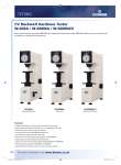
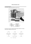
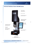
HARDNESS TESTING SYSTEM
UNIVERSAL
OPERATOR MANUAL
TABLE OF CONTENTS
P. 1
P. 2
P. 3
P. 3
P. 3
P. 4
P. 4
P. 5
P. 5
P. 6
P. 6
P. 7
P. 7
P. 8
P. 9
P. 10
P. 11
P. 12
P. 13
P. 14
P. 15
SPECIFICATIONS AND FEATURES
TB-U SETUP
MAINTENANCE
HANDLING AND INSTALLATION
GETTING STARTED
SELECTING SCALES
CONDUCTING A TEST
PRINTER SETUP
CHANGE DWELL TIMING AND DISPLAY VALUE RESOLUTION
LIMITS ALARM SETUP
HOW TO SETUP FOR CYLINDRICAL CORRECTION
HOW TO SETUP FOR SCALE CONVERSIONS
HOW TO RECALL STATISTICS
PS/2 EXTERNAL KEYBOARD CONNECTION
NIST TRACEABILITY
FRONT PANEL
FRONT VIEW OF TESTER
REAR VIEW OF TESTER AND BOTTOM OF HEAD
SERIAL PRINTER AND PC CABLE SCHEMATICS
TRU-BLUE U BASE MOUNTING HOLE LOCATION
TRU-BLUE U OPTIONAL ACCESSORIES
United’s North America Offices
United Calibration Corporation
Huntington Beach, CA
(714) 638-2322
Fax (714) 897-8496
www. tensiletest.com
United Testing Systems, Inc.
Flint, MI
(810) 732-2800
Fax (810) 732-2872
E-mail [email protected]
United Testing Systems
Canada, LTD.
225 Bradwick Drive, Unit 21
Concord, Ontario L4K 1K7
(905) 669-5327
Fax (905) 738-5051
E-mail: [email protected]
SPECIFICATIONS AND FEATURES:
ROCKWELL:
•
•
•
•
•
•
•
•
•
•
•
•
•
Regular Scales: A, B, C, D, E, F, G, H, K, L, M, P, R, S, and V.
Superficial Scales: 15N, 30N, 45N, 15T, 30T, 45T, 15W, 30W, 45W, 15X, 30X, 45X, 15Y, 30Y, and
45Y.
3-ASTM E-18 Dwell Time Settings plus NIST SRM timing.
Plastics Dwell Time settings per ASTM D-785.
Statistical summary including Average, Range, Standard Deviation, High, Low, and Number
of Tests.
Auto Correction hardness values for cylindrical parts.
Built-in ASTM E-140 Conversion Charts and ASTM A-370 Tensile Strength Values.
Parts IN/OUT of Tolerance Settings with Adjustable Audible Alert.
PS/2 connector for an external computer keyboard.
RS-232 interface port (9 pin).
Parallel printer port.
Identify test data for printer or database using a standard PC keyboard with the tester.
Bi-directional application of testing: Via elevating unit or control panel.
BRINELL:
•
•
Test Forces in Kg.:2, 2.5, 4, 5, 6.25, 7.8125, 10, 15.625, 20, 30, 31.25, 40, 62.5, 100, 120, 125, 150,
187.5 and 250.
Test Dwell Settings selectable in 1 sec. increments: 5-30
VICKERS:
•
•
Test Forces in Kg.: 3, 5, 10, 30, 50, 100, and 120.
Test Dwell Settings selectable in 1 sec. increments: 5-30
GENERAL SPECIFICATIONS:
•
•
Computer Controlled testing with digital closed loop control of force applications.
Machine uncertainty excluding test block and indenter variations less than 0.1 point
corresponds to 3.3 % GR&R for a 3-point tolerance.
• 4x20 Bright Vacuum Fluorescent display.
• Front panel controls with Piezo-Electric switches.
• Auto self-test and last test setup recall at startup.
• Parts Clamp, which can be used to secure irregular shaped or oversize parts.
• 20 bit analog to digital converters for force and depth measurements.
• Co-Axial mounting of Force and Depth transducers.
• Logical setup and operating menu from front panel keys.
• Manual, Hex Driver for indenters and Power Cord.
• Factory Certificate for Direct Verification of: Load, Depth, Hysterisis and Dwell Timing.
• 2-Year Factory Warranty.
• CE Certified.
• Throat depth is 5.5 inches.
. POWER REQUIREMENTS: 100- 240VAC 50/60 Hz 1 Phase 1 AMP.
. DIMENSIONS: 8'
'
W x 20'
'
D x 33.5'
'
H for the 10”, 37.5”H for the 14” and 41.5” for the 18”.
. APPROX WEIGHTS: 185 lbs. (10”), 195 lbs. (14”), and 205 lbs. (18”).
Page 1 of 15
TB-U User Manual
Revision 6 7/04
TB-U SETUP:
ENVIRONMENTAL REQUIREMENTS:
Indoor use only.
Altitude to 2000 M.
Temperature range 0 to 50 deg C.
Humidity - non-condensing.
Pollution degree 2.
POWER REQUIREMENTS:
100 TO 240 ∼ 50/60 Hz. 1 Phase 1 Amp max.
Transient overvoltages per overvoltage category II.
NOTE: The TB-U is designed to be energized continuously, therefore there is no
“ON/OFF” switch. Should it become necessary to de-energize the unit simply
disconnect the power cord from the rear of the tester.
GROUNDING:
Users having outlets other than the NEMA standard used in the USA must obtain the
proper IEC cord set for their local power system. Always make certain that the power
outlet used is properly grounded.
FUSE:
Type T 2A, located within the power inlet assembly. Littelfuse type 218002 per IEC 1272, rated 2A 250 Volts, or equivalent.
ACCESSORY LIGHT:
The optional HTA-280-IL work light requires a #89 lamp rated at 13.5 volts 0.58 Amps
only. Replacement lamps are available from, Gilway Technical Lamps, 800 West
Cummings Park, Woburn, MA 01801 USA.
Page 2 of 15
TB-U User Manual
Revision 6 7/04
MAINTENANCE:
WARNING there are no user serviceable parts or settings inside the Tru Blue U chassis.
There is a potential shock and mechanical hazard internally. Do not open the True Blue U
chassis under any circumstances. Contact your United representative for service.
HANDLING AND INSTALLATION:
The elevating screw must be fully raised before moving the TB-U. If the screw is not
raised it will prevent the machine from sitting level on a flat surface.
Lift the machine by the base and vertical column. Do not lift the unit by the elevating
screw or sheet metal covering of the head. The Tru-Blue U/10 tester weighs approximately
185 lbs. (84 Kgs), a minimum of two persons are needed to move it.
The machine must be located on a secure table or workbench. The tester should be isolated
from external vibration, as it may cause the machine to read erroneously.
A 3-inch (75-mm) diameter hole in the supporting surface must be located under the
elevating screw to allow lowering for maximum testing distance between the top of the
screw and indenter.
The machine may be secured to the optional TB-U Floor Stand (part # HTA-200-FS) or
other suitable workbench, using the ½-20 tapped holes in the corner gussets located under
the base.
GETTING STARTED:
The TB-U was designed for simple operation. Making changes to the tester setups and options
may be easily accomplished with minimal operator effort. The various Tester functions can be
accessed and changed by following the display prompts. The keyboard is comprised of six
individual buttons. Each keyboard button is represented by an “*” which corresponds to an
associated lighted “*” on the display. (See front panel illustration on page 10)
1. Press the MENU button then select ROCKWELL to access the TB-U ROCKWELL SETUP
menu. A list of options will appear on the display (see illustration). Changing the various
options and functions of the TB-U is accomplished from this menu.
Page 3 of 15
TB-U User Manual
Revision 6 7/04
Install an anvil into the top of the elevating unit. Ensure that the top and bottom of the anvil and
the top of the elevating unit is free of any rust, oil or dirt.
NOTE: Remove the “Parts Clamping Device” prior to installing an indenter.
2.
To install an indenter, loosen the indenter clamp screw using the 7/64” hex driver included
with the tester’s accessories. Insert the indenter and tighten the screw just enough to keep the
indenter from falling out. Place a test block or specimen on the anvil and press the
ENTER/START TEST button, wait approximately 3-4 seconds, then fully tighten the
penetrator clamp screw while the machine is applying the “Major Load”. This will ensure that
the indenter is properly seated.
SELECTING TEST MODE
Press the MENU button to access the TB-U TEST MODE SETUP menu. Select ROCKWELL,
BRINELL or VICKERS to enter the set up menu for the desired type of test. (See illustration
below). After selecting the desired test settings, press TEST to go to the “Ready for Test” screen.
CONDUCTING A TEST:
The Tru-Blue U offers the following two methods to conduct a test (for Rockwell scales only):
NOTE: Although either of the two methods may be used, Method # 1 will generally provide
for more consistent results.
1
Place the test specimen on the anvil and leave a small gap (approximately 1 mm or 1/16
inch) between the test specimen and the indenter. Press the ENTER/START TEST button
to activate the test cycle. When the test is finished, the penetrator will retract automatically
and the tester will be ready for the next test.
NOTE: If the gap between the indenter and the test specimen is too great (3mm or more)
the tester will indicate “Test Aborted”.
2. Place the test specimen on the anvil. Raise the elevating unit until the test specimen makes
contact with the indenter. Continue raising until a series of arrows (>>>>) appears across
the display and you hear the audible tone. The test cycle will now automatically begin.
When the test cycle is completed, the display will indicate “REMOVE PART” along with
the hardness value. Lower the elevating screw until there is a gap between the test specimen
and the indenter.
Page 4 of 15
TB-U User Manual
Revision 6 7/04
PRINTER SET UP
Press the MENU button then select ROCKWELL to access the TB-U ROCKWELL SETUP
menu.
Note: Ensure you have connected the proper cable and printer to the tester’s serial or parallel
port before setting the port options to the ON position.
To set up a printer output, press the PORTS button. SET OUTPUT PORTS will appear on the
display. Use the buttons to select the available settings for the desired configuration.
Press the ENTER button to return to the ROCKWELL SETUP menu.
CHANGE DWELL TIMING/ ROCKWELL VALUE RESOLUTION:
NOTE: Dwell times may be changed as required for the material being tested or user specific test
requirements. The TB-U is shipped with the dwell timing set at STANDARD.
Press the MENU button then select ROCKWELL to access the TB-U ROCKWELL SETUP
menu.
Press the DWELL/ DISPLAY button. SET DWELL/DISPLAY will appear on the display.
To change the Dwell timing press the TIMING button continue pressing until the desired dwell
time setting is reached.
Press the DISPLAY button to change the resolution of the Rockwell value displayed after making
a test. The resolution can be changed from ### (points) to ##.# (tenths), or ##.## (hundred’s).
Page 5 of 15
TB-U User Manual
Revision 6 7/04
Press the BRIGHT button to change the intensity of the display characters, continue pressing until
the desired brightness is displayed.
Press the ENTER button to return to the ROCKWELL SETUP menu.
LIMITS ALARM SETUP
The LIMITS option enables the user to establish hardness tolerances of parts being tested. The
tester will sound an audible alert, and flash a visual warning “OUT OF LIMITS” when the
displayed hardness value is above or below preset limits.
Press the MENU button then select ROCKWELL to access the TB-U ROCKWELL SETUP
menu.
Press the SET LIMITS button.
Press the DN buttons to lower the HI and LO Limits. Press the UP buttons to raise the limits.
Press the ENTER button to return to the ROCKWELL SETUP menu. Press the “BY 5 PTS”
button simultaneously with an “UP or DN” button to advance numeric selection in 5 point
increments.
HOW TO SET UP FOR CYLINDRICAL CORRECTION.
NOTE: It may be necessary to correct the Rockwell value obtained when checking convex curved
parts. Using the following setup the TB-U will automatically calculate the cylindrical correction
using the calculations per ASTM E-18:
Press the MENU button to access the TB-U ROCKWELL SETUP menu.
Page 6 of 15
TB-U User Manual
Revision 6 7/04
Press the CONV button and continue pressing until the desired size is displayed.
Press the NEXT button to return to the ROCKWELL SETUP menu.
HOW TO SET UP FOR SCALE CONVERSIONS
Press the MENU button then select ROCKWELL to access the TB-U ROCKWELL SETUP
menu.
Press the CONVERSION button and continue pressing to scroll to the desired material
conversion table. Press the NEXT button to enter the selection and continue to the next setup
menu, which will be CONVERT TO.
Press the CONVERSION button and continue pressing to scroll to the desired material
conversion. Press the NEXT button CONVERT TO will appear on the display. Push the STR
CONV button and continue pressing until the desired unit selection for strain is reached.
Press the NEXT button CONVERT TO SCALE will appear on the display. Press the SELECT
button until the desired scale is displayed. Press the NEXT button to return to the ROCKWELL
SETUP menu.
HOW TO RECALL STATISTICS:
The tester will automatically calculate statistics for any number of tests.
Press the READ STATISTICS button once and the tester will display AVERAGE (AVG),
STANDARD DEVIATION (STD), HIGHEST READING (HIGH), LOWEST READING (LOW),
and the RANGE. Press READ STATISTICS button to resume testing.
Page 7 of 15
TB-U User Manual
Revision 6 7/04
To remove test results from the statistics memory, press the CLEAR STATISTICS button once
the display will read “REMOVED FROM STATS” “CLEAR STATISTICS TO CLEAR ALL” or
“TEST TO CONT. To remove only the last reading and resume testing press the ENTER/START
TEST button. The display will return to the previous test setup and is now reading to resume
testing. To clear all statistical data press the CLEAR STATISTICS button. This will remove all
data from the last set of tests. The display will indicate READY FOR TEST # 1
PS2 EXTERNAL KEYBOARD CONNECTION
The True Blue U comes equipped with a PS-2 port for use with a PS-2 external keyboard.
To use this option, simply attach a PS-2 keyboard to the connector located at the rear of the
machine (see fig.2). You may enter a maximum of 20 alphanumerical characters and spaces that
will be stored in the tester’s memory. The text will be displayed at the bottom of the True Blue
display. This text (i.e. customer name, part # lot # or batch #) is sent to the RS 232 port
automatically for printing with the associated hardness data after each test. Use the backspace key
to erase last entry or ESC to clear all. This feature is compatible for use with United’s optional
SPC software.
SETUP FOR DIRECT READING OF BRINELL OR VICKERS INDENTATIONS
Note: The tester can only be calibrated to one hardness range at a time.
1. Press the MENU button, then select Brinell or Vickers. Connect a PS-2 keyboard to the tester.
2. Select the desired load and dwell times. Simultaneously press the MENU and TEST buttons
to activate the calibration program.
Page 8 of 15
TB-U User Manual
Revision 6 7/04
NOTICE
The Tru-Blue U was designed to meet the pending revisions to ASTM E-18. The new NIST
standard reference blocks are used for traceability on the scales currently available, for this reason,
readings may not be exactly the same as the original United Tru-Blue Hardness Testers.
Tru-Blue machines are verified using NIST traceable Force and Length standards. The Rockwell’s
reading accuracy is dependent upon the following variables:
1.
Applied forces.
2.
Dwell time of force application.
3.
Measurement of penetration depth
4.
The precise geometric shape of the diamond or ball indenter.
5.
The actual hardness of the test block.
NIST traceable standards have been used to control items 1, 2, and 3 very precisely. Every effort is
being made to maintain consistency in our diamonds and blocks.
Changes in standards are the result of ongoing procedural changes being recommended by NIST.
United is committed to stay abreast of all changes to standards and practices as defined by NIST.
Page 9 of 15
TB-U User Manual
Revision 6 7/04
ROCKWELL SETUP
PORTS *
* SET SCALE
CONV *
* SET LIMITS
* DWELL/DISP
TEST *
*
*
*
*
*
*
MENU
TB-U User Manual
Revision 5 9/02
Page 10 of 15
FRONT PANEL
TRU-BLUE II
MEAS
HRA
CONV N/A HRC
APPROX N/A KSI
CYL OFF
ROCKWELL HARDNESS TESTING SYSTEM
READ
STATISTICS
*
*
CLEAR
STATISTICS
*
*
ENTER/
TEST
MENU
MENU
*
*
USA
CLAMPING DEVICE
INDENTER CLAMP
INDENTER
ANVIL
ELEVATING UNIT
ELEVATING UNIT
COVER
NUT HOLDER
with ARMS
BUSHING
BASE
TB-U User Manual
Revision 5 9/02
Page 11 of 15
FRONT VIEW
OF TESTER
AUDIBLE ALERT
VOLUME
CONTROL
AC INPUT
FILTER WITH
MAIN AND
SPARE FUSE
PS-2
CONNECTOR
25 PIN PARALLEL
CONNECTOR
FOOT SWITCH JACK
-
REAR
PANEL
FUSE
9 PIN SERIAL
CONNECTOR
IDENTIFICATION
LABEL
LAMP
CONNECTOR
ANVIL AND INDENTER TRAY
TB-U User Manual
Revision 5 9 /02
Page 12 of 15
FRONT
PANEL
REAR VIEW OF TESTER
AND
BOTTOM OF HEAD
SERIAL PRINTER TO TESTER CABLE
DB-25P
DB-9S
FRONT
PRINTER
DATA SET READY
GROUND
TX DATA
RX DATA
DB-9S
TESTER
DB-9S
PC TO TESTER CABLE
JUMPERS
TX DATA
RX DATA
RX DATA
GROUND
PC
TB-U User Manual
Revision 5 9/02
Page 13 of 15
JUMPERS
TX DATA
TESTER
PRINTER AND PC CABLE
WIRING SCHEMATICS
FRONT
1.375
2.625
10.625
½ - 20 thread.
4 places.
3.00
2.625
1.375
2.625
Dimensions are in Inches
TB-U User Manual
Revision 5 9/02
Page 14 of 15
Tru-Blue U base
mounting hole location
TRU-BLUE U OPTIONAL ACCESSORIES
Small serial or parallel printer model HTA-036-SP
Floor Stand with out casters HTA-200-FS
Floor Stand with casters HTA-204-FSCA
United
United
Rockwell Test Blocks HTA-270-HTB.
When ordering, specify the scale
and range of each block.
Foot Switch for activation
of the test cycle HTA-290-FS
Rockwell Indenters
“A” Diamond HTA-240-AD
“C” Diamond HTA-220-CD
“N” Diamond HTA-230-ND
Ball indenters 1/16, 1/8, ¼ , ½ sizes.
Steel or Carbide spare balls.
TB-U User Manual
Revision 5 9/02
Page 15 of 15
Wide variety of Anvils are available.
2-½ inch Flat HTA-070-FA
¼ Spot HTA-080-SA
1-½ inch “V” HTA-090-VA
Raised “V” HTA-100-RVA