1
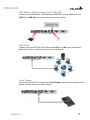
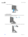
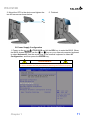
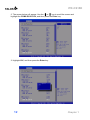
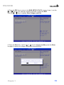
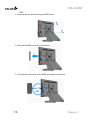
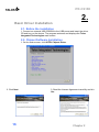
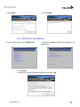
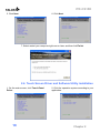
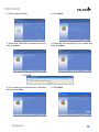
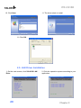
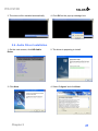
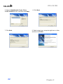
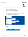
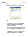
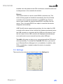
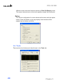
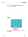
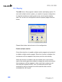
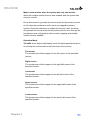
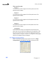
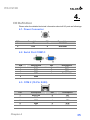
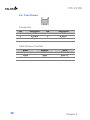
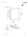
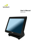
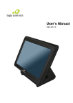
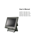
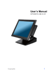
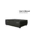
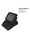
User’s Manual
ITR-CS15D
ITR-CS15D
Copyrights
©2012
TALOS INTEGRATED
TECHNOLGIES. All rights reserved. The information
in this document is subject to change without prior
notice in order to improve reliability, design and
function and does not represent a commitment on the
part of the manufacturer.
Safety Statement for
Lithium Battery
This document contains proprietary information
protected by copyright. All rights are reserved.
No part of this manual may be reproduced by any
mechanical, electronic, or other means in any
form without prior written permission of the
manufacturer.
CAUTION
RISK OF EXPLOSION IF BATTERY IS
REPLACED BY AN INCOORECT TYPE.
DISPOSE OF USED BATTERIES ACCORDING
TO THE INSTRUCTIONS
All trademarks are property of their respective
owners
Liability Disclaimer
In no event will the manufacturer be liable for
direct, indirect, special, incidental, or
consequential damages arising out of the use or
inability to use the product or documentation,
even if advised of the possibility of such damages.
TALOS INTEGRATED TECHNOLOGIES
411 BRADWICK DR. UNIT# 11
VAUGHAN, ONTARIO L4K 2P4
Regulatory Information
FCC Notices
Copyrights
i
ITR-CS15D
Contents
Copyrights .................................................................................................i
Liability Disclaimer ...................................................................................i
Regulatory Information.............................................................................i
FCC Notices.......................................................................................................... i
Safety Statement for Lithium Battery ......................................................i
Contents....................................................................................................ii
1. Hardware Setup....................................................................................4
1.1. Packing Contents ......................................................................................... 4
1.2. Quick Tour .................................................................................................... 5
Front View and Side View .............................................................................. 5
Back Panel I/O ............................................................................................... 6
1.3. HDD Replacement ........................................................................................ 6
1.4. Basic Peripherals Installation ..................................................................... 8
Power Adapter ............................................................................................... 8
USB Mouse, USB Keyboard and USB ODD .................................................. 9
LAN Cable...................................................................................................... 9
Cash Drawer .................................................................................................. 9
Customer Display......................................................................................... 10
MSR............................................................................................................. 14
1.5. Adjust Angle ............................................................................................... 15
1.6. Turn on the device...................................................................................... 15
2. Basic Driver Installation ....................................................................16
2.1. Before the installation................................................................................ 16
2.2. Chipset Software Installation .................................................................... 16
2.3. VGA Driver Installation .............................................................................. 17
2.4. Touch Screen Driver and Software Utility installation ............................ 18
2.5. LAN Driver Installation............................................................................... 20
3. Touchscreen Control Panel Quick Guide ........................................23
3.1. Launch TouchKit Utility ............................................................................. 23
3.2. General........................................................................................................ 24
3.3. Settings ....................................................................................................... 25
3.4. Tools............................................................................................................ 28
3.5. Display ........................................................................................................ 30
3.6. Edge Compensation .................................................................................. 32
4. I/O Definition.......................................................................................35
4.1. Power Connector ....................................................................................... 35
ii
Contents
ITR-CS15D
4.2. Serial Port COM1/3..................................................................................... 35
4.3. COM 2 (10-Pin RJ50) .................................................................................. 35
4.4. Cash Drawer ............................................................................................... 36
5 Specification........................................................................................37
Contents
iii
ITR-CS15D
1.
1. Hardware Setup
1.1. Packing Contents
1.
ITR-CS15D X 1
4. RJ50 to DB9 COM port adapter cable X 1
2. Power Adapter X 1
5. IO/Cable Cover X 1
3. Power Cord X 1
6. Drive and Utility DVD X 1
4
Chapter 1
ITR-CS15D
1.2. Quick Tour
Front View and Side View
A.
The LED indicator will glow green when power is on.
The LED indicator will blink red when the HDD is accessed.
A.
Customer Display mounting
hole cover
D.
Power switch
B.
HDD tray
E.
I/O cover
C.
MSR cover
Chapter 1
5
ITR-CS15D
Back Panel I/O
A.
B.
C.
D.
E.
DC in
COM 2 (10-pin RJ -50)*
F.
COM1
USB 1/2
LAN 1
LAN 2
G.
H.
I.
J.
K.
CD/DIO (for cash drawer)
CF card slot
USB 3/4
COM3
VGA
CAUTION
* Note: Please use 10-pin RJ50 connector, 8-pin RJ45 is incompatible.
1.3. HDD Replacement
1. Loosen and remove the screws fixing the HDD tray.
2. Pull out the HDD tray slightly and softly.
6
Chapter 1
ITR-CS15D
3. Disconnect the SATA cable connector and the SATA power cable connector.
4. Loosen and remove the four screws fixing the HDD, and then remove the HDD
from the HDD tray.
5. Install the new HDD onto the device in reverse order.
Chapter 1
7
ITR-CS15D
1.4. Basic Peripherals Installation
1. Remove the IO panel cover from the device.
2. All cables and wires from peripherals to the POS device are recommended to
be fed through the base in the direction as shown below.
WARNING
Before the cable cover is removed, please make sure the power is off.
Power Adapter
Connect the DC cable to the DC in jack.
8
Chapter 1
ITR-CS15D
USB Mouse, USB Keyboard and USB ODD
Connect your USB Mouse, USB Keyboard USB ODD or other USB devices to
USB 1/2 or UBS 3/4 ports on the back panel of the device.
LAN Cable
Connect one end of RJ-45 LAN cable to the LAN 1 or LAN 2 port on the back
panel of the device, another end to your internet device.
Cash Drawer
Connect one end of RJ-11 cable to the Cash Drawer port on the back panel of the
device, another end to your cash drawer.
Chapter 1
9
ITR-CS15D
3. Install the IO panel cove.
Customer Display
A. Hardware Installation
1. Remove the two screws and the VFD mounting hole cover from the device,
and then pull out the connector from the device.
2. Adjust the hinge of the VFD, and then connect to the device as shown below.
10
Chapter 1
ITR-CS15D
3. Mount the VFD to the device and tighten the
two M3 screws as shown below.
5. Finished.
B. Power Supply Configuration
1. Power up the
ITR-CS15D and hit the DEL key to enter the BIOS. When
the BIOS screen appears use the
or
key on your external computer keyboard
to select Advanced. Use the arrow keys of the external keyboard to select IO
Configuration, and then press the ENTER key.
WARNING
Never enable the 12V power without the customer display attached and
be sure to disable the 12V power before removing the customer display.
Chapter 1
11
ITR-CS15D
or
key to scroll the screen and
2. The screen below will appear. Use the
highlight the COM6 RI/12V/15V, and then press the Enter key.
3. Highlight 12V, and then press the Enter key.
12
Chapter 1
ITR-CS15D
4. Press the ESC key to return to the BIOS SETUP UTILITY screen of step 1, use the
or
key on your external computer keyboard to select the EXIT.
or
key to highlight Save Changes and Exit.
Use the
5. Press the Enter key, use the
or
key to highlight the [Ok], press the Enter
key again to save your voltage configuration and exit BIOS.
Chapter 1
13
ITR-CS15D
MSR
1. Remove the two screws fixing the MSR cover.
2. Remove the MSR cover from the device.
3. Connect the connectors of the MSR assembly to the device.
14
Chapter 1
ITR-CS15D
4. Tighten the two M3 screws to fix the MSR
assembly as shown below.
5. Finished.
1.5. Adjust Angle
1.6. Turn on the device
1. Make sure all peripherals and cables are connected properly.
2. Press and hold the power switch until the power indicator on the front panel
glows green.
Chapter 1
15
ITR-CS15D
2.
2. Basic Driver Installation
2.1. Before the installation
1. Connect an external USB CDROM to the USB power and insert the driver
CD and turn on the device. The program autoruns and displays the Talos
Integrated Technologies main screen.
2.2. Chipset Software Installation
1. On the main screen, click INTEL Chipset Driver.
2. Click Next.
16
3. Read the License Agreement carefully and clic
Yes.
Chapter 2
ITR-CS15D
4. Click Next.
5. Click Finish.
2.3. VGA Driver Installation
1. On the main screen, click VGA Driver.
2. Click the operation system according to your
application.
3. Click Next.
4. Read the License Agreement carefully and click Yes.
Chapter 2
17
ITR-CS15D
5. Click Next.
6. Click Next.
7. Select restart your computer right now or later, and then lick Finish.
2.4. Touch Screen Driver and Software Utility installation
1. On the main screen, click Touch Panel
Driver.
18
2. Click the operation system according to your
application.
Chapter 2
ITR-CS15D
3. The procedure starts.
4. Click Next.
5. Check the Install PS/2 interface driver box
and click Next.
6. Select an item according to your needs, and
then click Next.
7. Click OK.
8. If you want to use Multi-Monitor, check the
box and click Next.
Chapter 2
9. Click Next.
19
ITR-CS15D
10. Click Next.
11. The driver starts to install.
11. Click OK.
2.5. LAN Driver Installation
1. On the main screen, click VIA 6130 LAN
Drive.
20
2. Click the operation system according to your
application.
Chapter 2
ITR-CS15D
3. The driver will be installed automatically.
4. Click OK on the pop-up message box.
2.6. Audio Driver Installation
1. On the main screen, click HD Audio
Driver.
2. The driver is preparing to install.
3. Click Next.
4. Select “I Agree” and click Next.
Chapter 2
21
ITR-CS15D
5. Check “VIA HD Audio Codec Drive
v7.300 30.090715” box, and then click Next.
7. Click Next.
22
6. Click Next.
8. Select restart your computer right now or later,
and then lick Finish.
Chapter 2
ITR-CS15D
3.
3. Touchscreen Control Panel Quick Guide
3.1. Launch TouchKit Utility
There are two alternatives to launch TouchKit.
Option 1:
Under Microsoft Windows XP, click “start” menu and select “Programs”,
under ”TouchKit” menu, click “Configure Utility”.
Option 2:
icon on the task bar to launch TouchKit utility.
Click
Chapter 3
23
ITR-CS15D
3.2. General
The General tab in Touchkit utility shows all of TouchKit touchscreen
controllers installed as below, including RS232, USB and PS2 interfaces.
Add
The function button is used for serial RS232 controllers only. Press this
button to search the TouchKit serial controllers connected with the
COM ports of the device. Whenever it finds a new TouchKit serial
controller, a new serial controller icon object will be shown in the
controller list window automatically.
USB TouchKit device supports plug and play, the icon object for USB
controller will be shown in the controller list window automatically when
the USB controller is connected with the USB port of the device. And,
the icon object for the USB controller will disappear automatically as
soon as the device was removed from the USB port of the device.
TouchKit PS2 driver support PS2 mouse and TouchKit touchscreen
controller. It can works with both PS2 mouse and TouchKit
touchscreen PS2 controller. After the TouchKit PS2 driver was
24
Chapter 3
ITR-CS15D
installed, this utility assumes the PS2 touchscreen controller exists and
is always shown in the controller list window.
Remove
This function button is used for serial RS232 controllers only. This
button will be grayed and disabled automatically when the selected
controller in the controller list window is not RS232 type. Press to
remove and uninstall the selected serial RS232 controller from the
device. Then, this serial RS232 icon object in controller list window
disappears automatically.
USB TouchKit device supports plug and play, the icon object for USB
controller will be shown in the controller list window automatically when
the USB controller is connected with the USB port of the device. And,
the icon object for the USB controller will disappear automatically as
soon as the device was removed from the system USB port.
TouchKit utility does not allow you to remove/uninstall the PS2 device
driver dynamically. To uninstall the TouchKit PS2 driver, you need to
go to Windows Device Manager to do un-installation. In addition, after
PS2 un-installation, it needs to reboot the device to complete
un-installation.
3.3. Settings
There are function buttons and check boxes in the Settings tab.
Chapter 3
25
ITR-CS15D
Beep
Beep On Touch
Check this check box to enable driver to generate a beep sound when
touch touchscreen state is switched from untouched to touched state.
Beep On Release
Check this check box to enable driver to generate a beep sound when
touchscreen state is switched from touched state to untouched state.
Frequency
Drag the slider to adjust this frequency to control the beep sound
frequency generated by the driver.
Duration
Drag the slider to adjust this duration to control the beep sound
duration.
Linearization Style
TouchKit utility provides you with both 9 points and 25 points
calibration for linearization. You can select the suitable linearization
type.
Double Click Time
Double Click Time is used to set double click time. Change this value
will affects the double click behavior for all of the mouse devices
connected to the device. Two continuous clicks at the same area within
this specified time period will be recognized as a double click event.
26
Chapter 3
ITR-CS15D
Double Click Area
Double click area is used to set the double click area. Change this
value will affects the double click behavior for all of the mouse devices
connected to the device. Two continuous clicks with this specified area
in the specified double click time will be recognized as a double click
event.
Mouse Emulation Mode
Change the emulation mode by pressing on this button.
Normal Mode
Normal mode behaves mouse button down and mouse move. You can
select this mode to select object, and dragging the object.
Click On Touch
With this Click On Touch mode, the driver emulates a mouse click
event when the touchscreen state was switched from un-touched state
to touched state. Then, the driver always generate mouse move event
and is tracking the touch position until the touchscreen state switched
to un-touch state.
Click On Release
With this Click On Release mode, the driver emulates a mouse click
event when the touchscreen state was switched from touched state to
un-touched state.
Click On Touch without moving cursor
With this mode, the driver behaves similar as Click On Touch mode.
The cursor does not move to the touch position except the first touch
point.
Click On Release without moving cursor
Chapter 3
27
ITR-CS15D
With this mode, the driver behaves similar as Click On Release mode.
The cursor does not move to the touch position except the lift-off point.
Option
You can set configuration for some advanced functions with this option
button. Press this button, a pop up property sheet window will be
popped up and shown as below.
3.4. Tools
There are function buttons and check boxes in the Tools tab.
28
Chapter 3
ITR-CS15D
4 Points Calibration, Clear and Calibration, and Linearization
button
Click the one of three these buttons and follow the instruction on the
screen to do the screen calibration.
Draw Test
After clicking this button, you can do the drawing test by drawing any
path on the screen as shown below.
You can remove all paths you drew by clicking Clear, or exit this screen
by clicking Quit.
Chapter 3
29
ITR-CS15D
3.5. Display
TouchKit driver utility supports multiple monitor and display system. To
work with multiple monitor system, you need to do proper configuration
to map the touchscreen working area to the correct system display
area. You can do such configuration with this property page shown as
below,
Please follow below instructions to do the configuration:
Enable multiple monitor
Check this check box to enable multiple monitor support and uncheck it
to disable multiple monitor support. When this function is disabled, the
touchscreen will be mapped to the primary monitor automatically.
When this function is enabled, user can double click on the monitor
area in the monitor geometry window to assign the monitor area where
the touchscreen will be mapped. In other word, the touchscreen will
work with the selected monitor. Then, the selected monitor area
rectangle line will be changed to be white and the other monitor
rectangles line will be grey.
30
Chapter 3
ITR-CS15D
Map to main monitor when the system has only one monitor
When the multiple monitor function was enabled, and the system has
only one monitor.
Driver allows user to generate the mouse event for the primary monitor
or not when the touchscreen which were not mapped to primary
monitor. Check the check box to enable this function, then, the driver
will generate the mouse event for the primary monitor even through the
touchscreen was configured as other monitor mapping and multiple
monitor function enabled.
Operation Mode
TouchKit driver support split display mode for those applications which
do not map the touchscreen to the full screen of the monitor.
Full screen
The touchscreen will be mapped to the full screen of the specified
monitor.
Right screen
The touchscreen will be mapped to the right half screen of the
specified monitor.
Left screen
The touchscreen will be mapped to the left half screen of the
specified monitor.
Upper screen
The touchscreen will be mapped to the upper half screen of the
specified monitor.
Lower screen
The touchscreen will be mapped to the lower half screen of the
specified monitor.
Chapter 3
31
ITR-CS15D
Other operation mode
Quarter 1
The touchscreen will be mapped to the first quarter area of the
specified monitor display.
Quarter 2
The touchscreen will be mapped to the 2nd quarter area of the
specified monitor display.
Quarter 3
The touchscreen will be mapped to the 3rd quarter area of the
specified monitor display.
Quarter 4
The touchscreen will be mapped to the 4th quarter area of the
specified monitor display.
Customized
If the touchscreen needs to be mapped the area other than the
above area, user can define the mapping area for application. With
this mode, the driver does not correct the mapping area when the
display resolution changed. It needs to do configuration setting again
whenever the display resolution changed.
3.6. Edge Compensation
Edge Compensation property page contains functions of Edge
Compensation for Top, Bottom, Left, Right, X Axis and Y Axis.
32
Chapter 3
ITR-CS15D
In some cases, if it is difficult to touch items at the edges of the touch
panel, you can set adjustment to reach the edges of the screen
image.
Top
If you set the Edge to "Smaller", TouchKit will reduce the horizontal
position of the top edge. If you set the Edge to "Larger", TouchKit
will extend the horizontal position of the top edge.
Bottom
If you set the Edge to "Smaller", TouchKit will reduce the horizontal
position of the bottom edge. If you set the Edge to "Larger",
TouchKit will extend the horizontal position of the bottom edge.
Left
If you set the Edge to "Smaller", TouchKit will reduce the vertical
position of the right edge. If you set the Edge to "Larger", TouchKit
will extend the vertical position of the left edge.
Right
If you set the Edge to "Smaller", TouchKit will reduce the vertical
position of the right edge. If you set the Edge to "Larger", TouchKit
will extend the vertical position of the right edge.
In some cases, cursor will be behind the finger when you touch the
panel. If you can not see the cursor when you touch down the panel,
you can set X Axis or Y Axis to move the cursor.
Offset X Axis
If you set the Offset X Axis to Smaller, cursor will be moved a pixel of
X Axis to left.
If you set the Offset X Axis to Larger, cursor will be moved a pixel of
Chapter 3
33
ITR-CS15D
X Axis to right.
Offset Y Axis
If you set the Offset Y Axis to Smaller, cursor will be moved a pixel of
Y Axis to top.
If you set the Offset Y Axis to Larger, cursor will be moved a pixel of
X Axis to bottom.
Edge Compensation Switch
You can check Support Edge Compensation check box to
enable/disable this function from left corner.
Edge Compensation Button
Click +10% or -10% button to adjust the smaller or larger of edge.
If you click +10% button, the top, bottom, left and right edges will
extend 10% of orientation to touch screen, and cursor will be moved
10 pixel of X and Y Axis to right and top.
If you click -10% button, the top, bottom , left and right edges will
contract 10% of orientation to touch screen, and cursor will be
moved 10 pixel of X and Y Axis to left and bottom.
Click Default button to resume to the default value.
34
Chapter 3
ITR-CS15D
4.
4. I/O Definition
Please refer the detailed technical information about all I/O ports as followings.
4.1. Power Connector
PIN
1
2
Description
+19V
+19V
PIN
3
4
Description
GROUND
GROUND
4.2. Serial Port COM1/3
PIN
1
2
3
4
Description
DCD
RXD
TXD
DTR
5
GND
PIN
6
7
8
9
Description
DSR
RTS
CTS
RI / 5V /12V
4.3. COM 2 (10-Pin RJ50)
PIN
Description
PIN
Description
1
RI/5V/12V
6
RX
2
DSR
7
GND
3
RTS
8
CTS
4
GND
9
DTR
5
TX
10
DCD
Chapter 4
35
ITR-CS15D
4.4. Cash Drawer
Connector
PIN
Description
PIN
Description
1
GND
4
P24V
2
D_OUT0
5
D_OUT1
3
D_IN
6
GND
Cash Drawer Control
36
Status
Address
Value
Open
280H
Bit 4 = 0
Close
280H
Bit 4 = 1
Read Status
281H
Bit 0 = 0/1
Chapter 5
ITR-CS15D
5.
5 Specification
Chapter 5
37
ITR-CS15D
Main Board
®
CPU
Chipset
Intel AtomTM Processor D525
®
Intel ICH8-M
System Memory
1 x 204 Pin DDR3 SO-DIMM Socket, up to 4GB
Thermal Solution
Fan-less
OS
Windows XP/ XPe/ WES, WEPOS, POSReady, Windows 7 *, Linux*,
®
®
Display
TFT LCD Size
15”
Brightness
250 nits
Resolution
1024 x 768
Touch Screen
5-wire Resistive Type
Tilt Angle
0°~90°
Storage Device
HDD
Compact Flash
1 x 2.5" SATA
1 x slot compact flash type II
I/O Ports
VGA
USB
LAN
6 x RS-232 Pin9 ,w/ RI/5V/12V Selectable by BIOS
COM 1 : RS-232/422/485, DB-9
COM 2 : RS232 , RJ50 10 pins
COM 3 : RS232 , DB-9
COM 4 : RS232 , Internal pin header
COM 5 : RS232 , Internal 15-Pin header with PS/2
COM 6 : RS232 , Internal pin header for Customer Display
1 x VGA
4 x USB 2.0
2 x Gigabit Ethernet by RJ-45, Support Wake on LAN
Cash Drawer
1 x RJ-11 (Power Pin 24V)
Serial
Others
Wall mount
Support VESA Mount
Power Input
External adapter, 135W, 19VDC input
Color
Black
Material
Plastic / Aluminum
EMC& Safety Compliance
FCC / WEEE / RoHS /
Weight
7.8 Kg (appox.)
Dimension
365 W x350 Hx260 D(mm) (appox.)
Operation Temperature
0°C ~ 35°C
Storage Temperature
-20o ~ 60oC
Storage Humidity
20 – 85% RH, non-condensing
Audio
2W speaker x 2 * Please contact supplier for detail infomation.
38
Chapter 5
ITR-CS15D
Optional Accessories
Customer display: VFD Attached, 20 columns x 2 lines, RS-232 Type
MSR-Front Type, 3 Tracks, PS/2 Type
MSR-Side Type, 3 Tracks, PS/2 Type & Finger Print, USB Type
MSR-Side Type, 3 Tracks, PS/2 Type & i-Button, PS/2 Type
12.1” 2nd Display
Specifications are subject to change without notice.
Chapter 5
39