1
12 Operation
The charger is controlled by a single two position switch located on the front or rear panel of the
charger.
12.1 Engaging
Switch to “ON-Position“. The red LED will illuminate. The charger is ready to use.
12.2 Maximum Charge Current
Note: The max. Charge current may not be reached when the battery is old and worn out. It is also
reduced during absorption and float mode (see graph above).
12.3 Pulse Charge Mode
Press the pulse charge button to start the pulse charge mode.
12.4 Current Limits
Press the current limits button to reduce output current to 50% of rating current. Press this button if
your battery size is smaller than 200Ah 12V system or 100Ah 24V system.
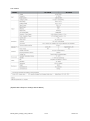
The max. charge current will be limited to 24A for model EC-1245 and 12A for model EC-2423.
12.5 Power down
Switch to „OFF-Position“. The LED’s are dark. The charger output is OFF. The charger may be connected to the battery at all times.
Warning! Do not charge non-rechargeable batteries!
13 Display
13.1 Status LED
Red LED ............................................................................................................................... Power ON
Steady yellow ...................................................... Fast charge mode, bulk and absorption / equalizing
Steady green .................................................................................. Float charge mode, battery is full.
13.2 LCD Meter Models Version “M” only
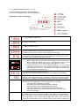
The LCD Display shows actual charge status: Bulk/Equalize Charge or Float Charge.
It also indicates the approx. Battery Level: 25%, 50%, 75% and 100%
Manual_EASY_Charger_1245_2423.doc
8/12
Version 2.4