1
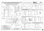
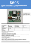
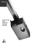
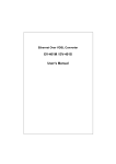
MC4 Insta llation and user ma nua l for sliding gate motor MC4 with B631 control boa rd MAIN CHARACTERISTICS OF THE MOTOR MC4 AND CONTROL BOARD B631 Power 300W Feeding Motor absorption 1.3A Kind of limit switch MC4C : mechanic limit switch MC4MFC : magnetic limit switch Capacitor Protection grade Torque Speed Pushing power Max. weight of the gate Thermal protection Isolation class Temporary service 14uF IP44 20Nm 0.16m/s 400N 400Kg 150°C I 30% Max power output Motor power regulation Protection fuses 230Vac Protection fuses 24Vdc Output voltage for commands Blinker Pilot lamp “Gate Open” Working time Forewarn time Inversion time Automatic closing time Working temperature 230Vac 10% (50-60 Hz) 0.5Hp / 350W from 30% to 100% 6A/T 1A/T 24Vdc 10W max 230Vac 200W max 24Vdc 3W max 160s / 80s max (can be switch on) 2.5s (can be switch off) 1.5s 3s - 80s -20°C / + 70°C Limit switch opening FCA and limit switch closing FCC mechanical (MC4C) or magnetic (MC4MFC) Obstacle detection module (optional) Electronic regulation of the power Test of triacs and safeties at every manoeuvre Push at any start of manoeuvre, can be switch off Slowing down at the end of manoeuvre in closing, can be adjust or switch off Delay time in the inversion of manoeuvre, in order to avoid mechanical damages to the motor Easy setting of the motor direction by dipswitch whether it is installed on the right-hand or on the left-hand of the gate Visualization of functioning and input state by LEDs Step/step command programmable by DIP with 4 different modalities ALT/STOP command Partial Opening Command (pedestrian) APP Safety opening SA for protection in the opening phase Photocell FOT Radio module MODP433 433.92 MHz with decoding B&B Rolling-Code, memorization up to 60 radio-controls Memory module extractable for transferring the radio-controls to other boards Possibility of remote programming by “MASTER” radio-control. 1 IMPORTANT WARNINGS This equipment is exclusively intended for the usage it was conceived, any other kind of usage is to be considered improper and therefore dangerous. The installation and the maintenance (every 6 months) of the product have to be carry out only by specialized staff according to the current laws. The feeding voltage has to be supplied from an efficient differential pushbutton, which has to be tested and settled according to the current laws and also a suitable external independent disconnecting switch, which has to be adjusted on the current charge. Throughout the installation procedure the board has to be switch off. The disposition of materials has to be done in accordance with the current laws. Adopt all the precautions to integrate the safety of the gate in accordance with the current laws. Choose the shortest ways for the cables and keep power cables away from the control ones. Before the installation assure that there is the stopping beat of the gate. For the adjustment of the maximum torque of the gear motor, follow the current laws. According to the European laws on security, we suggest to connect an external pushbutton for switching off the feeding during maintenance on the gate. Verify that all the installed devices are effective and efficient. Post-up sign-boards in a readable way to inform the presence of an automatic gate Please remember that we are in the presence of an automatic device fed with electric energy, therefore use it with all the precautions. In particular we exhort: Don’t touch the device with wet hands and/or with wet or naked feet; Cut the energy before opening the command box and/or the motor; Don’t pull the feeding cable to disconnect the plug; Command the motorized gate only when it is completely visible; Stay out of the action range of the gate, if this is in motion: wait until it’s completely stopped; Don’t let the children or the animals play in the proximity of the gate; Don’t let the children use the radio-control or other command devices of the gate; Do a periodical maintenance; In case of damage, cut the energy and move the gate manually only if it is possible and safe. Avoid any self-made intervention but call specialized stuff. The no observance of the described notes could cause damages to persons, animals or objects. In such case the producer can’t be considered responsible. 2 TYPICAL INSTALLATION 1 2 3 4 5 6 7 8 9 10 Motor gear MC4 Blinker Antenna Key selector Photocell Column Rack Limit switch Advising sign Mechanical stops ATTENTION! Set DIP 8 in ON or in OFF according to the motor is installed either on the left or on the right hand of the gate (see pag. 8) PRE-INSTALLATION CHECK Before doing the installation is suggested to do the following checks and operations: The structure of the gate must be sturdy and appropriate; During the run, the gate doesn’t have to present too much sideways slide skids. The system of wheels/lower rail and rollers/upper runner must work without too many frictions; To avoid the gate derailment, is necessary to install the stop beats of the sliding motor, whether in the opening or in the closing, and a second roller/upper runner in full observance of the current law. Remove the possible manual lock in the pre-installed gates; Put on the bottom of the gate the junction box of feeding cables (025-50mm) and of external connection (photocell, blinker, key selector, etc.) MOTOR INSTALLATION FIXING OF THE PLATE Fig.1 – Fixing by screw-anchors PROGET is responsible only for the products it produces and commercializes. The gate, when automate, becomes a machinery and therefore subjected to the Machinery Directive. It is duty of the installer to verify the safety of the whole installation. WARNING: PROGET in not responsible for damages to persons, animals or objects caused by modifications, alterations or improvements done to its products without its permission. Fig.2 – Drowning into the concrete Respecting the overall sizes, fix to the ground the base-plate by 4 sturdy screw-anchors (fig.1), or drown it into the concrete (fig.2). Plan one or more hoses for the passage of the power lines. Is suggested, after a few manoeuvres of the motor, to do a further tighten. WARNING: It is necessary to know the dimensions of the rack in order to calculate the right position of the counter-plate. FIXING OF THE RACK FIXING OF THE MOTOR TO THE PLATE For the fixing of the motor proceed unscrewing and taking away the cover of the motor. Set the gear on the plate. Insert the two socket (or square screws). Release the motor and set the gate at its complete opening. Put a rack element on the pinion, and fix it with screws and spacing bars to the gate. Manually move the gate putting the pinion into line with the last spacing bar. Definitely fix the rack element. For a correct positioning of the other elements and in order to assure their straightness, it’s necessary to use a rack element as reference and support. It is also necessary to assure a space of 2 mm between rack and pinion so that the gate weight doesn’t burden on the pinion of the motor gear. It’s important to strongly tighten the two square screws, making sure that for the complete run of the gate, the motor gear is well fixed on the ground. In case the regulation allowed by the rack wouldn’t be sufficient, it’s possible to compensate the height of the motor gear by acting on the 4 screws. FIXING OF MECHANICAL LIMIT SWITCH (MC4C) The gate must be equipped with beaten whether in opening then in closing, which will prevent the gate derailment. The position of the beaten must assure that limit switch brackets don’t collide with pinion. Put manually the gate in opening position, leaving a space between 30 to 50 mm between the gate and the mechanical stop (beaten), according to the weight of the gate. Fix the limit switch bracket trough the dowels so that the limit switch is pressed. Repeat the operation with the gate in closing. 4 MAINTENANCE The motor gear MC4 is provided with a permanent lubrication of grease so it doesn’t need of maintenance; nevertheless his good working depends on the state of the gate too, therefore we will describe some operations in order to have always an efficient gate. Warning: none apart the maintainer, who must be a specialized technician, could command the gate in automatic during its maintenance. It is suggested therefore to cut electric energy, avoiding also electric shocks. If, otherwise, the energy has to be present for possible verifications, is recommended to check or disable any command devices (radio-controls, pushbuttons, etc) excepted the one used by the maintainer. ORDINARY MAINTENANCE INSTRUCTION FOR MAGNETIC LIMIT SWITCHES (MC4 MFC) The gate must have stops in opening and in closing in order to avoid the derailment of the gate. The position of the stop must assure that limit switch brackets don’t collide with the pinion. Manually move the gate in opening position and leaving a space between 30 and 50 mm between the gate and the mechanical stop, according to the weight of the gate. Fix the bracket of the magnetic limit switches with the proper pivot. Repeat the operation with the gate in closing position. Each of the following operations must be done when we realize the need and in any case every 6 months. 1) Mechanic maintenance: Clean from debris the rail and the respective wheels; Check the good fixing of the motor and the relative plate; do an unlocking manoeuvre in order to be sure that the mechanism will always be efficient. 2) Electric maintenance: Check the good state of the safety devices; Check the efficiency of the electronic power regulation Check the efficiency of the ground system (differential). Test the differential switch once a month pushing the test button on the pushbutton. USAGE OF THE MANUAL RELEASE In case of lack of electric energy, act on the manual release device and move the gate manually. SOUTH polarity NORTH polarity Insert the unlocking key and rotate it counter clockwise of 90°. Pull the handle until it is perpendicular to the motor gear. DIMENSIONS CLAMPS DESCRIPTION AND ELECTRIC PLAN 1, 3 4, 5 24 25 26 27 47 Feeding 230Vac 10% (50-60 Hz) Ground connection Output for blinker LAMP, 230Vac 200W max Output +24Vdc 10W max (common tension and safeties) Output Pilot lamp “Open Gate” SCA, 24Vdc 3W max (NO) Input Step-Step command PP (NC) Input of command ALT/STOP (NO) Input of command of partial opening APP 22 Reference 0V 23 24 30 31 41 42 Output feeding for safeties check +24Vdc CK Output common +24Vdc (NC) Input photocell FOT (NC) Input safety Opening SA Input of radio antenna Input of radio antenna cable shield (NC) Normally closed entrance, if not used it has to be bridge with the common (clamps 24, 24) (NO) Normally opened entrance, it has to remain opened if not used LIMIT SWITCHES and POWER SUPPLY CONNECTOR CAPACITOR and MOTOR CONNECTRO FCC AMPEROSTOP MODULE TAP FCA RAL RF TP FUS1 1A/T RADIO RECEIVER CHECK ON 1 2 3 4 5 6 7 8 TRANSFORMER CONNECTOR MAST CANC EEPROM MODULE FUS2 6A/T PP ALT APP RX ERR FOT SIC TERRA MOTORE PROG 4 BLINCKER 230Vac max 200W 5 25 PILOT LAMP "GATE OPEN" 24Vdc max 3W 24 6 Antenna Photocell FOT Safety opening SA Common +24Vdc EARTH 22 23 24 30 31 41 42 Safeties check+24 CK 24 25 26 27 47 0V 5 Partial opening APP 4 ALT (Stop) 3 Step-step PP FEEDINGS 230Vac 2 Common +24Vdc 1 DIPSWITCH DIP Position Function ON 1 OFF FOT 1 2 3 4 5 6 7 8 Description Modality STOP-REOPEN: Even in opening than in closing , the gate stops and at the release of the photocell FOT after 2 seconds it reopens. ON 1 ON FOT Modality REOPEN: makes the inversion of motion in closing phase. 1 2 3 4 5 6 7 8 ON 2 OFF FOT/TP At the passage trough the photocell the pause time restarts (if trimmer TP isn’t at the minimum). FOT/TP The passage trough the photocell sets the pause time at 5s (if trimmer TP isn’t at the minimum). 1 2 3 4 5 6 7 8 ON 2 ON 1 2 3 4 5 6 7 8 3 OFF 4 OFF ON 3 OFF 4 ON ON 3 ON 4 OFF ON 3 ON 4 ON ON Command PP Function modality OPEN-CLOSE Command PP Function modality OPEN-STOP-CLOSE-STOP Command PP Function modality REMOTE OPENING: Opens, only at complete opened gate is possible to close. Command PP Function modality CONDOMINIUM: makes only the opening. The closing takes place at the expiring of pause time. Working time Maximum working Time 80s. Working time Maximum working Time 160s. 1 2 3 4 5 6 7 8 1 2 3 4 5 6 7 8 1 2 3 4 5 6 7 8 1 2 3 4 5 6 7 8 ON 5 OFF 1 2 3 4 5 6 7 8 ON 5 ON 1 2 3 4 5 6 7 8 ON 6 OFF Forewarn Blinker and motor start immediately together. Forewarn The blinker starts 2.5s before of the manoeuvre. 1 2 3 4 5 6 7 8 ON 6 ON 1 2 3 4 5 6 7 8 ON 7 OFF Push Starting Push, disabled. Push At the start of manoeuvre the board gives a brief push at maximum power. 1 2 3 4 5 6 7 8 ON 7 ON 1 2 3 4 5 6 7 8 ON 8 OFF Direction Defined direction of motion (motor and limit switch as by serigraphy and manual instruction). Direction Direction of motion inverted (motor and limit switch with inverted meanings with reference to serigraphy and manual instruction). 1 2 3 4 5 6 7 8 ON 8 ON 1 2 3 4 5 6 7 8 CHECK JUMPER Jumper CHECK open Position CHECK CHECK CHECK close Function Description Check sic. Enables the check of safeties at every start of manoeuvre. Check sic. Disable the check of safeties. DESCRIPTION OF TRIMMERS TAP RAL RF ON Trimmer Description TAP Working Time for partial opening (input APP) RAL Slowing down Time in closing, between 0s and 8s. RF Electronic power regulation of motor. TP Pause time for automatic closing (3s - 80s, at the minimum it disables) TP CHECK 1 2 3 4 5 6 7 8 MAST CONNECTION OF PHOTOCELLS INSTALLATION PROCEDURE Standard connection (jumper CHECK closed, without check securities) of the photocell FOT (same procedure is for the SA): CHECK 1) Check the fixing of motor and gate. 2) Adjust opening and closing limit switches in order to stop the gate at the desired position. 3) At board switched off, set DIP 8 according if the motor is installed either on the left or on the right hand of the gate. 22 23 24 30 31 41 42 0V 24Vdc FOT TX FOT WARNING! During the installation: LEDs’ RX and ERR blink alternatively The slowing down isn’t functioning The check of securities isn’t functioning RX FOT Connection without FOT check (jumper CHECK closed) MC4 to the left DIP 8 is OFF ON 1 2 3 4 5 6 7 8 The control board B631 is provided by a feeding voltage of +24V CK for the control (check) of photocells or similar safeties (input FOT and SA). To allow to the B631 board to control the safeties you have to connect the positive feeding of each transmitter to the clamp 23 (+24V CK) and open the jumper CHECK. ON 1 2 3 4 5 6 7 8 MC4 to the right DIP 8 is ON CHECK 22 23 24 30 31 41 42 FOT (30) 0V 24Vdc (24) TX FOT RX FOT 4) Put the gate at the middle of his run and switch on the B631 board. Verify that no buzz, overheated or undesired command of the motor are present. 5) Verify that the LEDs’ ALT, SA, FOT, FCC, FCA are lighted on (input closed on the common) and the LEDs’ PP and APP are off (input open). 6) Reset the settings of the board: close the jumper MAST and push simultaneously buttons PROG and CANC: the LEDs’ ERR and RX blink together; after approx 5s the board is reset and LEDs’ ERR and RX blink alternatively (installation phase). SA (31) MAST CANC TX SA RX SA FOT and SA with safey check (jumper CHECK open) During the installation phase (LEDs RX and ERR blink alternatively) the board checks which securities are connected to the feeding of +24V CK (clamp 48) according to the plan above. The securities whose TX transmitters are connected to the +24V common feeding (clamp 24) are not controlled. At the end of the installation and before each manoeuvre, the under check securities will be controlled through the deactivation and the following reactivation of the +24V CK output and the simultaneous control of the securities state. If this control fails (e.g.: photocell doesn’t work) the move will be stopped and the ERR LED will blink 5 times. To disable the securities check, close the jumper CHECK. In order to connect more securities to the same entrance (e.g.: FOT), connect the normally closed contacts (NC) in series. 8 5s PROG 7) Program the DIPs 1, 2, 3, 4, 5, 7, 8 in OFF and the DIP 6 in ON (forewarn enabled). Open the jumper CHECK to check the securities before any manoeuvre, otherwise close the jumper to disable this function. 8) Adjust the trimmer RF1 at the middle of its run (power regulation of approx 50%), and the trimmers RAL, TP and TAP at the minimum. 9) Verify that the first manoeuvre of the gate, after the switching on, is an opening. If not, verify connections or that there are not safeties enabled. If the motor buzzes or it works only in one direction, check the right connection of the common or capacitor. 10) Adjust trimmer RF1 in order to regulate the push of the motor, according to current laws. 11) Let to the gate to do 3 complete cycles (opening and closing) ) without the intervention of securities, so that the board is able to learn working times of the gate. At the third manoeuvre LEDs’ ERR and RX stop to blink alternatively: it means that the installation phase is over. 12) Adjust the trimmer TP in order to set the pause (automatic closing time) from 0s to 80s approx. When the trimmer TP is at the minimum disables the automatic closing. 13) Adjust the trimmer TAP to set the partial opening time of the gate. 14) Adjust the trimmer RAL to set the slowing down time in closing, from 0 to 8s. When the trimmer RAL is set at the minimum it disables the slowing down. 15) Adjust the dipswitches according to the desired motor functioning. COMMANDS AND FUNCTIONING MODALITIES MODALITY OPEN-CLOSE (DIP 3 OFF and DIP 4 OFF) Pushing button PP or a button of the radio-control, the board makes alternatively an opening and a closing phase. MODALITY OPEN-STOP-CLOSE-STOP (DIP 3 OFF and DIP 4 ON) Pushing button PP or a button of the radio-control, the board makes alternatively opening-STOP-closing-STOP. MODALITY “REMOTE OPENING” (DIP 3 ON and DIP 4 OFF) Pushing button PP or a button of the radio-control, the board makes an opening; only when the gate reaches the limit switch or when the working time is expires, it is possible to close the gate. During the closing phase the gate reopens. This modality is suggested in presence of lot of interferences on the radio transmission or when many users can command simultaneously the gate. MODALITY “CONDOMINIUM” (DIP 3 ON and DIP 4 ON) Pushing button PP or a button of the radio-control, the board makes an opening; closing takes place automatically only with the pause time (trimmer TP). This modality is recommended in condominiums with lot of users. PARTIAL OPENING (APP) A n.o. pushbutton connected between clamps 24 and 47, commands a partial opening of the gate, which is adjustable by trimmer TAP. If during the phase of partial opening arrives a command of complete opening the gate executes this last one. PUSHBUTTON ALT (STOP) Pushing the button ALT (stop) that is connected to the clamp 27 makes the board stop any motion of the gate. The automatic closing is suspended. The restart of motion takes place only by a new command. FOREWARN Putting DIP 6 in ON, the blinker is lighted on for approx 2.5s. to indicate the beginning of any manoeuvre. SLOWING DOWN In order to have a precise and quiet stop of the gate it is possible to set a period of slowing down in closing before the stop of motor. WARNING: because of the clearances or particular features of some motors, in case of repeated inversions of motion without reaching the full opening or closing, the working time increases and the beginning of the slowing down can assume different positions, till to be not visible. A full opening or closing reestablish the right operation. To activate and adjust the slowing down time in closing, use the trimmer RAL, from 0s to 8s approx. AUTOMATIC CLOSING Adjust trimmer TP for the desired closing time. When you don’t need any automatic closing, set the trimmer TP at the minimum. If during an automatic closing the photocells intervene and the DIP 2 is in OFF, the internal timer will be restart. If the DIP 2 is in ON, the closing takes place 5s after the release of photocells. SAFETY OPENING “SA” The intervention of the safety opening SA (clamp 31) during an opening movement determines the immediate stop of the gate and the restart in closing for 2s. The restart of motion can take place only with a new command and it will be, for sure, a closing movement. PHOTOCELL FOT The photocell FOT installed at the entrance of the gate has to be connected to clamp 30. With the DIP 1 in OFF (modality stop-reopen) passing trough the photocell, even in opening than in closing , the gate stops and after 2s from the release, the gate reopens. With the DIP 1 in ON (modality reopen) only in closing and passing trough the photocell the gate stops and reopens after a brief pause; during opening it makes no effect. CHECK OF SAFETIES The control board is provided by a feeding voltage of +24V CK (clamp 23) for the control of photocells or similar safeties (input FOT and/or SA). Connecting photocells as by electric plan and the opening of the jumper CHECK, the functionality of the safeties is verified before any manoeuvre. OBSTACLE DETECTION MODULE (OPTIONAL) The obstacle detection module (amperostop) checks the functioning of the motor during the normal motion (push and slowing down excluded). If it is detected a situation that stops the motor, after approx 1 second the control panel reverses the motion for about 2s, the LED ERR and the pilot lamp SCA blink for 7 times. The restart of movement can take place only by a new command and it would be certainly in the opposite side. SIGNALLING LED AND “GATE OPEN” PILOT LAMP Generally, the LED RX signals the power of the radio transmission received, the LED ERR and the pilot lamp SCA (clamp 25) signals that the gate is open or an error situation. The alternate blinking of the LEDs’ RX and ERR signals the phase of installation (see pag.8). LED ERR Description of the error 1 blink 2 blinks 3 blinks 4 blinks 5 blinks 7 blinks 8 blinks Error in the memory module EEPROM Expired working time In the installation, found wrong limit switch. Error in the check of triacs (probably damaged) Error in the check of safeties before any manoeuvre. Intervention of obstacle detection module Limit switch found before its correct position. RECORDING OF RADIO-CONTROLS CONNECTION OF THE ANTENNA It necessary to connect the antenna with maximum 5m of 50ohm Coax cable to the clamps 41 and 42, knowing that in order to have the best performance, the antenna must be installed as high as possible, close to the receiver, in an area free of radio magnetic interferences and far from metallic elements. For short ranges is enough to connect a piece of rigid cable (17cm for the frequency 433.92MHz). 22 23 24 30 31 41 42 Antenna RECORDING PROCEDURE a) Verify that pushing the button of the radio control, the RX LED of the control board blinks. b) If the RX LED of the board blinks without having push any button on the radio control, it means that we are in presence of radio interferences or that other radio-controls are transmitting. In this conditions, it is suggestible you do not proceed through the recording phase. c) Push the button PROG on the control board and push the desired button of the radio-control till the RX LED remains always lighted on (recording done). MAST CANC PROG 5s b) During the first 5 seconds the RX LED will blink slowly. At the end of deletion the Rx and ERR LEDS will remain lighted on. Release the buttons now. INSTALLATION OF THE “MASTER” RADIO-CONTROL (Ety4 or Emy4) a) Close the jumper MAST: the LED ERR blink quickly. Push the button PROG and simultaneously the button of the radio-control (Ety4F or Emy4F) to record as “MASTER”, till the LED RX remains always lighted on. MAST CANC PROG MAST CANC PROG b) Release buttons and the RX LED will switch off. Open the jumper MAST c) To verify the correct recording of the MASTER, push simultaneously buttons 1 and 4 of the radio-control: The LED RX on the control board will blink slowly for 10s. d) Release the buttons. NOTE: d) Release buttons and verify the correct functioning. DELETING OF A RADIO CONTROL a) First, push the button CANC on the control board then, for 1s, the desired button to be delete on the remote control. Now the RX LED remains lighted on (deleting done). MAST CANC Only one remote-control can be recorded as “MASTER”. The recording of a new “MASTER” eliminates automatically the previous recorded. REMOTE RECORDING OF NEW RADIOCONTROLS BY THE “MASTER” RADIOCONTROL In order to avoid the opening of the box where the board or the radio receiver is stored, the control board is supplied by a function that allows to remote recording new radio-controls. To do this it is necessary to record a radio-control of the series Ety4 or Emy4 as “MASTER”. a) Push simultaneously the buttons 1 and 4 of the radio-control “MASTER”. The LED of the radio-control will remain lighted on for 10s. b) Push (at least for one second) within this period, the button of the radio control we want to record. It is possible to record more radiocontrols and more pushbuttons in sequence. The procedure ends after 10 seconds from the last recording. PROG b) This procedure must be done for every button you want to delete. TOTAL DELETING OF ALL RADIO-CONTROLS a) Left the jumper MAST open. Push simultaneously buttons PROG and CANC of the Control Board. 10 3 4 1 2 Em y c) Test the new radio-controls recorded. In case it is not working one of the following situations could be happened: the command of the radio control MASTER (1 and 4) was not right received, the command of the new radio-control was not right received or the memory is full (max 60 radio controls). REMOTE DELETING OF RADIO CONTROLS USING THE “MASTER” RADIOCONTROL a) Push simultaneously on the “MASTER” radio-control the buttons 1-2-3. The LED of the radio-control will remain lighted on for 10s. b) Within this period push the button of the radio-control to be deleted. 3 4 1 2 Em y c) Wait 10s and then verify the correct deleting. d) To delete other pushbuttons repeat the procedure from the beginning (point a). MC4 SPARE PARTS 1 2 3 4 5 6 7 8 9 10 11 12 13 14 15 16 17 18 19 20 21 22 23 24 25 26 27 28 29 30 31 32 33 34 35 36 37 38 39 40 41 42 43 44 45 46 390V6X60TCE 500CALSC-50 470S11062H506 410AED10 440C6203 470R6250 410SE6X32 450AT256210 430VD48 440C6204 410AD25 480RM4Z18 390V6X12TR 500 FLANSC-50 450OR4337 450AT25407 440C6005 570DISTSC 490ALSEC 410L8X7X15 410L10X8X50 570RM3Z23 390V2-9X13C 600ETDATISC 430MSBL 450AT10197 490PSBOTT 520CPSC-50 400DGM10 570CSTAFFSC 410RFM8FTT 400GM8X35 410RD10 390V10X35TCE 390V5X70TCE 400DAM5 500SPOSC-50S 420S2151B-KA 500CORSC-50 190CR16M450 380F290X3 390V4-2X19S 570PRMIC 330M16A300G 550CABSC-50 12 47 48 49 50 51 52 390V4-2X9-5C 900ATRA 570TAPMOLL 430MFIN 570CAST 390V3-9X13C 53 54 55 56 900CT-1A 570CCT-1A 390V4-2X13I 570CSC CE STATEMENT OF CONFORMITY PROGET s.r.l declares that the product MC4 complies with the essential requisites contained in the following UE directives: - directive on the electromagnetic compatibility 89/336/EEC - directive R&TTE 99/05/EC - directive on the low voltage 73/23/CEE Applied laws of harmonization: EN60335-1, EN55014-1, EN55014-2, EN55081-1, EN55082-2, ETSI EN300220-3 PROGET s.r.l Via Europa, 3 31047 Ponte di Piave (ITALY) Phone: +39 0422 857377 Fax: +39 0422 857367 email: [email protected] Ponte di Piave, 20-01-2006 Officer In Charge: GINO BASSI The description and the electrical plan of this instructions guide are not binding. Although the main features of the device will be kept unchanged, Proget s.r.l. reserves itself at any time the faculty to improve the performance of the device even for commercial matters, and the right to up-date the instructions guide without any commitments. PROGET srl Via Europa, 3 31047 Ponte di Piave (TV) - ITALY tel.+39 (0)422 / 857377 fax +39 (0)422 / 857367 web: http://www.proget-beb.com email: [email protected] rev. 1.0.7, 07/2007 13