1
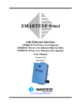
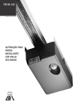
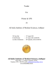
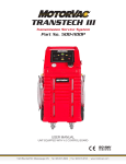
550
071
6
Silve
lox
Qual
ity
Syst
em
Rev.
05
(July
201
3)
OWNER’S MANUAL
Operation and Maintenance
Product:
Overlap sectional garage door
Model:
OVERLAP 2.0
Operation:
Manual and automatic
For Residential Use Only
Manufacturer: SILVELOX S.p.A.
Italy - 38050 Castelnuovo (Trento) - Viale Venezia, 37
Tel. +39 0461 755 755 Fax +39 0461 752 466
www.silvelox.com - [email protected]
OVERLAP 2.0
DRAFT
TABLE OF CONTENTS
1
2
PREFACE ......................................................... 3
OVERLAP GENERAL DESCRIPTION .............. 3
2.1 Product certification label ................................ 3
2.2 Danger warning labels .................................... 3
3
OVERLAP OPERATION ................................... 5
3.1 Manual operation of garage door .................... 6
3.2 Automatic operation of garage door ................ 8
3.3 In case of emergency ...................................... 9
3.4 Reset maneuver.............................................. 9
4
ELECTRIC CONNECTIONS AND ELECTRONIC
COMPONENTS ....................................................... 10
4.1 General overview .......................................... 10
4.2 Terminal Block .............................................. 11
4.3 Wiring diagram .............................................. 12
4.4 Timer-to-Close (TTC) adjustment .................. 13
4.5 LEDs description ........................................... 13
4.6 Internal buzzer .............................................. 13
4.7 Home automation contacts ........................... 14
4.8 Optional device prerequisites ........................ 14
4.9 Remote control (NOT for US&Canada) ......... 15
4.10 Remote control (for US&Canada) ................. 21
5
MAINTENANCE .............................................. 22
5.1
5.2
5.3
5.4
5.5
Visual inspection ........................................... 22
Door balance ................................................. 22
Opener safety device .................................... 22
Opener reversal ............................................ 22
Door lubrication ............................................. 23
6
CARE .............................................................. 25
6.1 Protective resin restoration ............................ 25
6.2 Paint restoration (stained or painted) ............ 25
6.3 Minor dents or scratches repair ..................... 25
6.4 Windows and windows insert cleaning .......... 25
6.5 Plastic and steel parts cleaning ..................... 25
7
TROUBLESHOOTING..................................... 26
7.1 Pulleys cables derailment.............................. 26
7.2 Automatic door malfunctions ......................... 26
8
LIMITED WARRANTY ..................................... 28
8.1 Limited Warranty Periods .............................. 29
8.2 Limited Warranty for Wood Parts .................. 29
8.3 Warranty disclaimer ...................................... 29
9
INSTALLATION BOOK ................................... 31
10 PERIODIC MAINTENANCE BOOK ................. 32
11 DISMANTLING ................................................ 34
12 ASSISTANCE AND ACCESSORIES .............. 34
USER MANUAL OVERLAP 2_0 AMARR v.2
g
1 PREFACE
Dear customer, we want to inform you about safety, maintenance and operating issues of your Silvelox garage door. If you correctly follow
all the instructions, the product will work as expected. The garage door is typically the largest moving object in the house. Improper
installation, operation or maintenance of a garage door can create a hazardous condition that can cause serious injury or even death.
WARNING
In the interest of safety this symbol means WARNING or CAUTION. Injury to people
and/or property damage may occur unless instructions are followed correctly.
WARNING
In the interest of safety this symbol means WARNING. Injury to people and/or
property damage may occur from electrocution or fire unless instructions are
followed correctly.
2 OVERLAP GENERAL DESCRIPTION
The Silvelox Overlap garage door is an innovative sectional garage door with an opening mechanism that does not need sliding bars and
tracks on the ceiling and requires less internal space. Overlap is equipped with a garage door opener (GDO) embedded in the crossbar
fixed to the wall. No visible and cumbersome motor unit is anchored to the ceiling. Operation commands are given via a radio transmitter or
with a wall push-button.
Operation features of the GDO:
Rated voltage: 100-120 V AC single phase – 50/60 Hz
Rated power: 200 W
Sound intensity: less than 70 dB (A)
2.1 Product certification label
In the internal side of the upper section, the ID label indicating all the data necessary for the identification of the garage door is present.
This label, together with the declaration of conformity, certifies that the product complies with the applicable standards (Figure 2-1 and
Table 2-1).
2.2 Danger warning labels
These labels indicate the danger from improper use of the door. They are the general warning label, wall station control button label and
the emergency release handle label (Figure 2-1 and Table 2-1).
USER MANUAL OVERLAP 2_0 AMARR v.2
pag.
3
Table 2-1
LABELS, GRIPPING POINTS AND SAFETY DEVICES
1
2
3
4
5
6
7
8
9
10
11
12
ID LABEL
GENERAL WARNING LABEL
WALL STATION CONTROL BUTTON LABEL
EMERGENCY RELEASE HANDLE LABEL
EMERGENCY RELEASE HANDLE
INNER HANDLE (OPTIONAL)
UPPER INNER HANDLE
LOWER INNER HANDLE
COURTESY LIGHT, VOLTAGE and
DIAGNOSTIC LEDs
PHOTO EYE
OUTER HANDLE (OPTIONAL)
LOWER OUTER HANDLE (OPTIONAL)
Figure 2-1 Interior door view
Figure 2-2 Exterior door view
USER MANUAL OVERLAP 2_0 AMARR v.2
pag.
4
3 OVERLAP OPERATION
IMPORTANT SAFETY INSTRUCTIONS
WARNING: To reduce the risk of severe injury or death
1. READ AND FOLLOW ALL WARNINGS AND INSTRUCTIONS
before to operate, perform maintenance or repair the garage door.
2. GARAGE DOOR SAFETY IS YOUR RESPONSIBILITY. Garage
doors, garage door openers, and electric transmitters are not toys.
Careless operation or allowing children to use garage door controls
can lead to serious injury or death. Discuss garage door safety with
your children, explain the dangers and outline emergency
procedures in the event of an accident.
3. CONTACT WITH A MOVING DOOR COULD CAUSE SERIOUS
INJURY. Teach children to keep their hands and fingers clear of the
garage door, section interface, track, and other door parts during
operation.
4. ALWAYS keep remote controls out of reach of children. NEVER
permit children to operate or play with garage door control push
buttons or remote controls.
5. PUSHBUTTON WALL CONTROLS SHOULD BE OUT OF THE
REACH OF CHILDREN. Mount at least ten feet away from the
garage door and at least five feet from the floor and where the user
can clearly see the moving garage door.
6. ONLY activate garage door when it can be seen clearly, it is
properly adjusted, and there are no obstructions to door travel.
7. ALWAYS keep garage door in sight until completely closed. NO
ONE SHOULD CROSS THE PATH OF THE MOVING DOOR.
8. NO ONE SHOULD GO UNDER A STOPPED, PARTIALLY OPEN
DOOR.
9. If possible, use emergency release handle to disengage the
operator ONLY when garage door is CLOSED. An unbalanced
garage door could result in an open door falling rapidly and/or
unexpectedly, causing SEVERE INJURY or DEATH.
10. NEVER use emergency release handle unless garage doorway is
clear of persons and obstructions.
11. After ANY adjustments are made, the opener reversal MUST be
tested.
12. Safety reversal system MUST be tested every month. Garage
door MUST reverse on contact with 1-1/2" (3.8 cm) high object (or
a 2x4 laid flat) on the floor. Failure to adjust the operator properly
may cause SEVERE INJURY or DEATH.
13. ALWAYS KEEP GARAGE DOOR PROPERLY BALANCED. An
improperly balanced door may not reverse when required and
could result in SEVERE INJURY or DEATH.
14. ALL repairs to cables, counter-weights assemblies and other
hardware, MUST be made by a trained door systems technician.
15. ALWAYS disconnect electric power to garage door opener
BEFORE making ANY repairs or removing covers.
16. Do not permit kids to play with packaging components (plastic
bags, boxes, Expanded polystyrene (EPS), sheet metals…) to
avoid any dangerous situations.
17. Do not operate the garage door in any different ways other than
those indicated in the present manual. Any different operation is
considered not reasonable and the producer declines any
responsibility.
18. Do not perform any maintenance or adjustment if the door is
moving.
19. Keep nearby the product a fire extinguisher with a capacity of 6 –
9 kg, for rooms up to 200 square meters.
20. Do not impair or try to repair any electrical or electronic part or
any other device related to safety, like: printed circuit board
(PCB), actuators, photo-eyes, limiting devices, LEDs.
21. SAVE THESE INSTRUCTIONS.
USER MANUAL OVERLAP 2_0 AMARR v.2
pag.
5
3.1 Manual operation of garage door
The garage door can always be opened or closed manually, without the aid of the electronic garage door opener. To operate manually,
follow the instructions listed below:
Opening from inside (Figure 3-1):
Unlock the door by pulling down the emergency release handle (1) or rotating downward the inner handle if present (1);
Grab the lower inner handle (2) and pull the lower section upward up to the maximum opening height.
Closing from inside (Figure 3-1):
Grab the lower inner handle (3) and pull it downward until the lower section reaches the lowest position;
Conclude the closing maneuver by pushing the upper section outward (4) until the door is closed.
Opening from outside with OPTIONAL OUTER HANDLES ONLY (Figure 3-2):
Rotate the outer handle (1) counter clockwise;
Grab the lower outer handle (2) and pull the lower section upward;
Grab the lower part of the lower section (3) and push it up to the maximum opening height.
Closing from outside with OPTIONAL OUTER HANDLES ONLY (Figure 3-2):
Grab the lower part of the lower section (4) and pull it downward;
Push the lower leaf downward using the outer lower handle (5);
Conclude the closing maneuver pulling the outer handle outward (6).
3.1.1
Safety devices for manual operation
The garage door in manual operation is provided with safety devices, to help prevent dangerous situations. Such devices are described
below:
In case of hand or fingers entrapment between the two sections, the lower section moves or can be pushed toward the inside of the
garage, avoiding serious injuries.
Perimeter seals between the two sections are made of EPDM rubber, with a tubular shape. Their purpose is to avoid possible injury to
fingers if inadvertently they are between the door sections.
Floor astragal is made of EPDM rubber and has the purpose to cushion the accidental impact against a body during the descent of a
panel, as well as to close the space between the door and the floor, with the door closed.
USER MANUAL OVERLAP 2_0 AMARR v.2
pag.
6
Figure 3-1 Opening/Closing from inside
Figure 3-2 Opening/Closing from outside (OPTIONAL)
USER MANUAL OVERLAP 2_0 AMARR v.2
pag.
7
3.2 Automatic operation of garage door
To open automatically, follow the instructions below.
Automatic opening/closing of the garage door:
1) If your remote control looks like that in Figure 4-4, press button (1). The door can also be opened/closed with the wall button
(optional installation) or with another remote control linked with an optional receiver;
2) The courtesy light, the external flashing light (optional) and the external buzzer (optional) are activated.
3) The door opening/closing movement starts up to the ending position.
4) Once the ending position is reached, the door automatically stops.
5) To stop the door during operation, press button (1) of the remote control (impulse mode OPEN/STOP/CLOSE); from any
intermediate position, the motor will turn off and the door will stop. If the door stopped during opening, press button (1) again and
door will continue to open. If the door stopped during closing, press button (1) again and the door will reverse to the fully open
position.
6) In case of power outage, during opening or closing, the door will stop in the actual position. When the power is restored, the door
does not move automatically. To reset door, close the door manually and then operate door automatically; alternatively, perform a
reset maneuver (Section 3.4).
WARNING
When the door is activated from a position other than perfectly closed, it performs the
reset maneuver (Section 3.4). During the reset maneuver, the force controls are higher than
typical, so take great care to avoid contact with the door during the reset maneuver.
The reset maneuver is signaled by the internal buzzer beeping and courtesy light flashing.
3.2.1
Safety devices for automatic operation
To help preventing dangerous situations, the garage door is provided with safety devices. Such devices are described below:
Electronic sensor system: photo-eyes installed on the internal walls of the counterweights boxes that control the reversal of the closing
of the door in the event of object detection. A red LED, placed in the proximity of the photo-eyes, indicates their operation.
"Amperostop" current control system: this system, in the presence of obstacles placed outside the working region of the photo-eyes,
blocks and reverses the movement of the door.
USER MANUAL OVERLAP 2_0 AMARR v.2
pag.
8
3.3 In case of emergency
During a power outage, or during monthly inspections, the garage door must be released to be opened manually. To release the door, with
door fully closed, pull down vertically on the red emergency release handle. The door may now be opened and closed manually following
the instruction of Section 3.1. If the door had to stop in an intermediate position due to voltage interruption or other cause, do not
use the release handle. For moving the door manually, slightly force its movement in the sense of opening or closing, until reaching the
disengagement of the opener. To re-attach opener, once the power is restored, simply push the transmitter or wall control button.
WARNING
Read carefully the following information regarding the reset maneuver.
3.4 Reset maneuver
Every time that the door loses its reference positions, once activated, it performs a reset maneuver. The reset maneuver is signaled by the
beeping of the internal buzzer and the flashing of the courtesy light. The door performs a closing maneuver with the "Amperostop” current
control set to a higher current level allowing the system to recalibrate. Pay particular attention during this operation; to reverse the door
during the reset maneuver, a bigger force is required than normal operation conditions. The door can lose the reference positions in the
following cases:
After a reversal due to "Amperostop" current control activation;
After a reversal due to photoeyes activation;
After a power outage occurred when the door was not in closed position;
After a manual door operation that does not leave the door in closed position;
After many door activations within short time intervals.
USER MANUAL OVERLAP 2_0 AMARR v.2
pag.
9
4 ELECTRIC CONNECTIONS AND ELECTRONIC COMPONENTS
4.1 General overview
The electric connections and the electronic components are located in the operator control unit box, immediately visible on the headbar, if the
headbar central cover is not in place (Figure 4-1). The electric connections/components are listed in Table 4-1, referring to Figure 4-2.
Figure 4-1
Table 4-1
Reference
1
2
3
4
5
6
7
/
Description
Terminal Block (seeFigure 4-3)
Built-in Receiver Controls (NOT for
USA&Canada)
Timer-to-Close (TTC) Control Button
Diagnostic LED
Voltage LED
Configuration Port
Courtesy Light LEDs
Internal Buzzer (not visible)
Figure 4-2
USER MANUAL OVERLAP 2_0 AMARR v.2
pag.
10
4.2 Terminal Block
Safety appliances and/or optional devices have to be connected to the terminal blocks (Figure 4-2 reference number 1). A close view of the terminal
blocks is presented in
Figure 4-3 and the contact descriptions are listed in Table 4-2. To facilitate the cable connections it is possible to remove the terminal blocks from
their sockets and place them back once the connections are placed. In Section 4.3, the wiring diagram can help to visualize the connections.
WARNING
To prevent possible SERIOUS INJURY or DEATH from electrocution or fire:
• Disconnect ALL electric and battery power BEFORE connecting ANY cable to the terminal block.
Table 4-2
CN1 Contacts
(Inputs)
15 - 14
16 – 13 (red - red)
16 – 12 (pink - blue)
8-7
8-5
8-4
8-2
8-1
CN2 Contacts
(Outputs)
11 - 10
9-8
7-6
7-5
13 -12
13 – 1
bridge 12 - 2
13 – 3
bridge 12 – 4
Description
Left Photoeye (tx)
Right Photoeye (rx)
Close NO
Stop NC
Open NO
Open / Stop / Close NO
NC
Description
2nd Channel Built-in Receiver FC
(not for USA&Canada)
External Buzzer (Optional) FC
Home Automation output 1 FC
Home Automation output 2 FC
Power 24 Vdc (max 500 mA, 12 W)
External Flashing Light (Optional)
Supplementary Light (Optional)
Figure 4-3
USER MANUAL OVERLAP 2_0 AMARR v.2
pag.
11
4.3 Wiring diagram
USER MANUAL OVERLAP 2_0 AMARR v.2
pag.
12
4.4 Timer-to-Close (TTC) adjustment
By default, TTC is set to off. TTC can be set to automatically close your garage door from the fully open position after a specified period of time
(1,3,5 or 10 minute intervals). The garage door opener will Beep and the courtesy light will Flash before closing the door.
To set TTC, please follow the instructions below:
With door closed and connected to the power, remove the headbar central cover;
Keep pressed for 3 seconds the TTC Control Button (Figure 4-2, referenced as number 3); the Diagnostic LED (Figure 4-2, referenced as number
4) will blink 2 times;
Press the TTC Control Button to set 1 minute closing interval; the Diagnostic LED will blink 1 time;
Press the TTC Control Button, within 10 seconds from the last operation, to set 3 minutes closing interval; the Diagnostic LED will blink 2 times;
Press the TTC Control Button, within 10 seconds from the last operation, to set 5 minutes closing interval; the Diagnostic LED will blink 3 times;
Press the TTC Control Button, within 10 seconds from the last operation, to set 10 minutes closing interval; the Diagnostic LED will blink 4 times;
Press the TTC Control Button, within 10 seconds from the last operation, to set to off the TTC; the Diagnostic LED will blink 5 times;
After 10 seconds from the last selection made, the TTC is set.
WARNING
In case of a voltage interruption during opening or closing, once the voltage is restored, the
door remains in the actual position. Close the door manually or perform the reset maneuver
(see Section 3.4).
4.5 LEDs description
A total of six LEDs are present in the operator control unit box:
The Diagnostic LED (Figure 4-2, referenced as number 4): it starts to blink (red color) in case of electronic anomalies;
The Voltage LED (Figure 4-2, referenced as number 5): it turns ON (green color) once the door is plugged to the power network;
The Courtesy Light LEDs (Figure 4-2, referenced as number 7): it is a group of four white LEDs; once the door is activated, they turn ON and stay
ON for 1 minute after that the door operation is completed.
4.6 Internal buzzer
The operator control box is equipped also with an internal buzzer. When the door performs a reset maneuver (see Section 3.4), the internal buzzer
will beep for the whole maneuver signaling that the current control is set to a higher potentially dangerous level to allow the door to re-define its
reference positions.
USER MANUAL OVERLAP 2_0 AMARR v.2
pag.
13
4.7 Home automation contacts
Two home automation free contacts (FCs) are present on the terminal block CN2 (Figure 4-3). Use these contacts to connect the door to home
alarm systems.
Home automation 1 is active when the door is opening;
Home automation 2 is active when the door is closing;
When the door is operated manually or during a reset operation, the contacts are open.
4.8 Optional device prerequisites
The following optional devices can be installed by the dealer:
External buzzer
External flashing light
Supplementary light
External receiver
These accessories have to be connected on the relays of the terminal block CN2 (see Table 4-2 and Wiring diagram of Section 4.3).
The specifics of the relays are:
Max 1 A @ 125 V AC (resistive load)
Max 1 A @ 30 V DC (resistive load)
Max 500 mA @ 230 V AC (resistive load)
Max 500 mA @ 125 V AC (inductive load)
Max 250 mA @ 230 V AC (inductive load)
Minimum load: 5 V, 10 mA
In the Wiring diagram of Section 4.3, the flashing light and the supplementary light are powered by the contacts 13-12.This is only a possibility; in
this case the absorption of the connected devices cannot exceed the capacity of the power contacts 13-12, which is: 24 V Dc, max 500 mA (12 W).
An external source of power might be preferable.
USER MANUAL OVERLAP 2_0 AMARR v.2
pag.
14
4.9 Remote control (NOT for US&Canada)
The remote operation of the door involves the use of portable transmitters (Figure 4-4). These transmitters can be 2-channels or 4channels and send the signal to the respective auto-learning receivers (built-in 2-channel receiver or optional 4-channel receiver for
outdoor use). The built-in 2-channel receiver is mounted onto the printed circuit board of the motorization and its first channel is used for
the open/stop/close function, while the second channel is useable when connected to the terminals of the relay. The external 4channels receiver (optional) is supplied in a plastic housing and can be installed inside or outside the garage. The transmitters leave the
factory “ready for use”, meaning that the cryptographic code of the transmitter is already programmed into the receiver.
The operation is of the impulse type. This means that the open/stop/close function of the garage door is made with a single key (1) of
the transmitter: with the first “click” the garage door opens while the next click determines the stopping (while the garage door is still
moving) or closing (if the door is entirely opened). The other keys ((2) – (3) – (4)) can be used to remotely control other functions. For
example when the second channel is used for activating a light it is required to activate the ON-OFF operation rather than the pulse
operation.
4.9.1
Transmitters
The principal technical characteristics of the transmitters are the followings:
Operating voltage: 3 V = with a button type battery CR2032 LiMn
Signal frequency: 433.92 MHz
Operating temperature: -10 / +55 ° C
It is recommended to not submit the transmitter to violent shocks, sources of heat and to direct sunlight.
Figure 4-4
USER MANUAL OVERLAP 2_0 AMARR v.2
pag.
15
4.9.2
Built-in 2-channel receiver
The 2-channel receiver controls are accessible through the hole in the control unit box (Figure 4-2 referenced numbers 2 and 3). A closer
view of them is presented in Figure 4-5, with their description in Table 4-3. The receiver can support 150 transmitters maximum.
To activate the 2nd channel, connect the external device cables to slot 11-10 of the CN2 terminal block (Figure 4-3).
Table 4-3
Reference
i
ii
A
B
C
D
Description
Jumper to assign the button (1) of the
transmitter (operation already performed at
the factory)
Jumper to assign the button (2) of the
transmitter (operation already performed at
the factory)
Jumper to entirely cancel all and functions
of the receiver (Reset)
Jumper to block all functions
Jumper to indicate how many transmitters
are memorized
Self-learning button
Figure 4-5
USER MANUAL OVERLAP 2_0 AMARR v.2
pag.
16
4.9.3 4-channel receiver (OPTIONAL)
The external 4-channels receiver is mounted in an ABS plastic housing for an optimal protection against atmospheric agents. It can work together
with the 2-channels receiver present on the door, to offer the maximum number of remotely controlled devices. Please refer to Figure 4-6, Table 4-4
and In Table 4-5 please find the description of the 4-channel receiver terminal block.
Table 4-5 for a detailed view and description of the receiver components. It is possible to fasten the receiver to a wall or on a pole (or a suitable
bracket); ensure that the supply voltage is either 12 or 24 Vdc. If problems are encountered with signals reception, it is necessary to install an
external antenna which is available on request. The antenna must be installed at the highest point possible and in an area which is free of obstacles.
The optimal efficiency is obtained when it is installed on a metal pole or concrete, avoiding materials such as wood or plastic. When the length of the
included cable is insufficient, it is recommended to replace it entirely with a low losses coaxial cable with an impedance of 52 Ohm (type RG58/U)
and to not exceed a length of 10 m (30 feet).
USER MANUAL OVERLAP 2_0 AMARR v.2
pag.
17
Table 4-4
Reference
1 to 12
13 - 14
i
ii
iii
iv
A
B
C
D
E
Description
Receiver terminal block
Output terminals for antenna connection
(see In Table 4-5 please find the
description of the 4-channel receiver
terminal block.
Table 4-5)
Jumper to assign a button of the
transmitter to the relay 1
Jumper to assign a button of the
transmitter to the relay 2
Jumper to assign a button of the
transmitter to the relay 3
Jumper to assign a button of the
transmitter to the relay 4
Jumper to entirely cancel all and
functions of the receiver (Reset)
Jumper to block all functions
Jumper to indicate how many
transmitters are memorized
Self-learning button
Red LED
Figure 4-6
NOTE: The buttons (1) and (2) of the transmitter are assigned respectively to channel 1 and 2 of the built-in 2-channel receiver.
In Table 4-5 please find the description of the 4-channel receiver terminal block.
Table 4-5
CONTACTS
DESCRIPTION
Power input 12 / 24 Vdc/Vac; terminal 1= (-) ; terminal 2= (+)
1 -2
When 12V power is used, it is necessary to insert the jumper close to the terminal
USER MANUAL OVERLAP 2_0 AMARR v.2
pag.
18
3 -4
NO relay 1
4 -5
NC relay 1
6 -7
NO relay2
7 -8
NC relay 2
9 -10
NO relay 3
11 -12
NO relay 4
13
Coaxial antenna – shield
14
Coaxial antenna – core
WARNING
Devices connections must be carried by an accredited technician.
The wiring must be done using cable of 2 x 1 mm2 / max 40 W (relay 1-2-3) or 100 W (relay 4).
USER MANUAL OVERLAP 2_0 AMARR v.2
pag.
19
4.9.4
Operation of the receivers (2- and 4-channels)
ON/OFF Mode
The standard operating mode of the transmitter-receiver system is of the impulse type. In other words, when one of the keys of the
transmitter is pressed, the corresponding relay on the receiver is closed and when the key is released, the relay is opened again. In some
situations, however, it may be preferable to activate the relay when the key is pressed for the first time, and that it stays activated until the
key is pressed again, especially when it is used to activate lighting. This mode of operation is called “ON-OFF”. To activate this mode it is
required to install a permanent bridge on the jumper of the corresponding relay (see Figure 4-5 and Figure 4-6).
WARNING! Never leave a permanent bridge on jumper referenced as “i” in Figure 4-5 of the 2-channel receiver.
Blocking mode
This mode is activated when a permanent bridge is inserted in jumper B of the receiver (see Figure 4-5 and Figure 4-6). In this mode it is no
longer possible to insert a code from a distance, activate the ON-OFF mode, or cancel a code.
De-activation of a pushbutton of a transmitter
If necessary it is possible to de-activate the function attributed to a key of a transmitter.
To de-activate the function, proceed as follows:
Remove the bridges that may be present on the jumpers of the receiver.
Press the self-learning button of the receiver and keep it pressed.
Press the pushbutton of the transmitter that must be cancelled.
Keep the pushbutton pressed until the red LED on the receiver illuminates.
Release the pushbutton of the transmitter and then the self-learning button.
De-activation of all transmitters (Reset)
In case of theft or disappearance of a transmitter, it is recommended to de-activate the functions of all transmitters in order to avoid
unpleasant consequences, by following the steps below:
Insert the bridge on jumper A of the receiver.
Press the self-learning button of the receiver for at least 7 seconds.
Release the self-learning button.
Wait until the red LED on the receiver is illuminated.
Remove the bridge of jumper A and place it on the adjacent free pin of the jumper.
NOTE: this operation must be performed both for the internal 2- and 4- channel receivers.
USER MANUAL OVERLAP 2_0 AMARR v.2
pag.
20
Restoring the functions of the transmitter keys and restoring another code (2-channel receiver)
Verify that the garage door is connected to the mains.
Insert the bridge on jumper “i” (see Figure 4-5).
Press the self-learning key, D, and keep it pressed.
Press key (1) of the transmitter and keep it pressed.
Wait until the red LED illuminates, then first release the key of the transmitter followed by releasing the self-learning button.
Remove the bridge of jumper “i” of the 2-channel receiver.
When the second channel is used, repeat the operations from point 2 to 6 for jumper “ii” and key (2).
Put the bridge on the adjacent free pin of the jumper.
Restoring the functions of the transmitter keys and restoring another code (4-channel receiver)
Verify that the 4-channels receiver has power on the terminals 1-2 (12-24 Vdc/Vac).
Insert the bridge on jumper “i” (see Figure 4-6).
Press the self-learning key, D, and keep it pressed.
Press the free key on the transmitter which will control relay 1 and keep it pressed.
Wait until the red LED, E, lluminates, then first release the key of the transmitter followed by releasing the self-learning button D.
Remove the bridge of jumper “1” of the 4-channels receiver.
Repeat, if necessary, operations from point 2 to 6 for the next jumpers and free keys on the transmitter.
When the assignment of all functions and keys is accomplished, put the bridge on the adjacent free pin of the jumper.
To re-program other transmitters, refer to the instructions in the next paragraph “Activating a new transmitter”.
Activating a new transmitter
It is necessary to have a transmitter that is already functioning and programmed (named “original transmitter”).
De-activate eventual other receivers installed in the vicinity, by temporarily cutting power.
Stand within 5 m (15 feet) from the garage door.
Press (1) and (2) together of the original transmitter.
Within 5 seconds, press a key of the transmitter to be activated.
For eventual other transmitters, repeat the steps described above.
USER MANUAL OVERLAP 2_0 AMARR v.2
pag.
21
4.10 Remote control (for US&Canada)
The operator is compatible with the Liftmaster 3-Channel Universal Receiver 850 LM which can be connected inside the headbar. The main features
of the 850LM are:
Three channels provide expanded remote control capacity: Channel 1 - 50 remotes, Channel 2 - 20 remotes, Channel 3 - 20 remotes
Multiple remote control options available to provide secure access from the safety and convenience of a vehicle
Compact design fits most gate and commercial door operators
Compatible with 811LM and all MAX remote controls
Power: 12-24VDC or 12-24VAC
Narrow-band on 310 MHz, 315 MHz, and 390 MHz Security+ 2.0™ Rolling Code and Encrypted DIP
Operational temperature from -35 to 65 degrees C; Storage temperature from -40 to 85 degrees C
Compliant with FCC Part 15
USER MANUAL OVERLAP 2_0 AMARR v.2
pag.
22
5 MAINTENANCE
Monthly safety checks of your garage door and opener, and an annual visit from a trained garage door technician, will maintain the safety
and smooth operation of your garage door.
5.1 Visual inspection
Visually scan tracks, cables, rollers, and pins for fraying, rupture, and other signs of wear. A trained garage door technician must replace
these items to ensure garage door safety.
5.2 Door balance
To test door balance, first disconnect electric opener while door is closed (use emergency release handle). Raise door to waist level and
slowly release. Door should hold in this position. If door drops or rises without assistance, call a trained door system technician to correct the
door balance.
5.3 Opener safety device
To test photo eyes, stand inside garage, safely away from path of door; push wall button to close door. As door closes wave an object in path
of photoelectric eye beam. The door should reverse and return to the fully open position. Photo eyes should be installed no more than 6’’
above the floor.
5.4 Opener reversal
Garage door openers manufactured after January 1, 1993 are required by Federal law to have advanced safety features that comply with UL
325 standards. To test reversal, door must be properly balanced. Open garage door fully, place a 1-1/2’’ thick piece of wood on the floor
under the center of the door. Stand inside garage, safely away from path of the door, push the transmitter or wall button to close door. The
door must reverse when it strikes the wood. If the door does not reverse, contact a trained garage door technician to adjust, repair, or replace
the opener or door.
WARNING
After door balance (if door not brought manually to closed position), photoeyes and/or
opener reversal tests, at the successive door activation, it will perform a reset maneuver
(see Section 3.4).
USER MANUAL OVERLAP 2_0 AMARR v.2
pag.
23
5.5 Door lubrication
WARNING
All the lubrication procedures of the door must be performed with the door closed
and disconnected from the source of supply.
TABLE 5-1 SUGGESTED LUBRICATION PROCEDURES
ACTIVITY DESCRIPTION
REFERENCE FREQUENCY SUGGESTION
Grease the plastic strikers of the closing latches on the upper side of the upper section.
Figure 5-1 A 12 MONTHS
Grease both pins of the arms: upper pin inside the crossbar, lower pin on the side of the upper
section.
Figure 5-1
B,E
Grease both pins of the cables to the lower section, by inserting the grease in the slot of the
cable in contact with the pin.
Figure 5-1 C 12 MONTHS
Grease rollers.
Figure 5-1 D
12 MONTHS
12 MONTHS
Use Lithium
Base Grease
EP2
Use Lithium
Base Grease
EP2
Use Lithium
Base Grease
EP2
Use Lithium
Base Grease
EP2
WARNING! DO NOT GREASE CABLES
If you are not confident doing these operation, contact a trained garage door technician
USER MANUAL OVERLAP 2_0 AMARR v.2
pag.
24
Figure 5-1 Lubrication points (for each detail there is also the opposite side)
USER MANUAL OVERLAP 2_0 AMARR v.2
pag.
25
6 CARE
To maintain the appearance and safety of your garage door, regularly clean and inspect the door and the area in which the door operates.
Wipe out, using a cloth dampened with water, any dust or dirt on the exterior surface of sections, at least one time per year. If necessary,
use only mild soap, avoiding alcohol-based detergents or ammonia. In case of doubt or difficulty, ask to qualified service personnel.
6.1 Protective resin restoration
The potential slight loss of pigment that may occur in the process of cleaning the wood surface with a damp cloth is a normal phenomenon
that affects all paint coatings of superior quality and does not alter the characteristics or duration of the film. In order to preserve the
characteristics of the wood finish of the Silvelox door and to keep surfaces always fresh and active in their protective capacity, you should
re-apply the initial thickness of the applied resin every 2 to 3 years, which over time is worn away. Before proceeding with resin application,
you have to perform a careful cleaning of the wooden surface to eliminate the accumulation of dirt and atmospheric chemicals which may
be very corrosive. Use the Silvelox RENOVATION KIT designed for this purpose. The RENOVATION KIT contains two specific products,
Special Cleaner for wooden surface cleaning and Top Finish for resin restoration.
6.2 Paint restoration (stained or painted)
To renew the finish on the wood surface:
•
Remove any dirt deposited on the wood with a cloth moistened with water;
•
Sand the whole surface of the door face with a 220 grit sandpaper;
•
Clean the door from dust with a dry cloth;
•
Apply two coats of paint; in the case of stain coating, use a brush; in the case of paint, use a spray.
Ensure that the room temperature is higher than 10 °C (50 °F), that the wood is not faced to a temperature above 35 °C (95 °F) and not in
direct sunlight, and that there is no moving dust in the surrounding area. Acrylic resin in aqueous solution finishing products can be ordered
directly from the manufacturer, or purchased in a good retail paint store.
6.3 Minor dents or scratches repair
In case you want to remove small dents or scratches, you should use a colored wax putty, available in any specialized store and apply it
directly on the part to be repaired without subsequent painting.
6.4 Windows and windows insert cleaning
Use a soft cloth and common household glass cleaner.
6.5 Plastic and steel parts cleaning
We recommend to use non-aggressive neutral detergents of common use for household cleaning (Warning: cleaners should not contain
abrasive elements). Slight oxide glazes on AISI 316L stainless steel parts, can be removed with Scotch-Brite 3M sponges. Use the sponge
only in the same direction of the grain.
USER MANUAL OVERLAP 2_0 AMARR v.2
pag.
26
7 TROUBLESHOOTING
7.1 Pulleys cables derailment
WARNING
In the event of pulley cable derailment, do not try to unlock or repair any equipment.
To repair the system, contact a trained garage door technician.
7.2 Automatic door malfunctions
In the event that you experience malfunctions of the door with the GDO, check if door works manually. If so, evaluate the possibility of
solving the problem by adopting the following suggestions:
Problem
A) The door does not work and the voltage indicator LED on
the crossbar is turned off (the door can only be operated
manually)
B) The door does not work and the voltage indicator LED on
the crossbar is turned on
Possible cause
1) wait for power reactivation
2) some protection fuses may have been activated
3) the power plug is not inserted correctly in the socket
1) the battery of the remote controller is depleted
2) contact an accredited garage door technician
3) restore the correct power plug connection into the power
socket
4) contact an accredited technician to repair the wiring
1) clean the photo-eyes covers and/or align them properly if
accidentally bumped. If door is still not working, contact a
trained garage door technician.
2) grease the striker of the upper section. If door is still not
working, contact a trained garage door technician.
1) wait for power reactivation; to manual operate the door,
slightly force the door movement with inner handle until the
GDO is disengaged.
2) remove the obstacle; if door is still not working, contact a
trained garage door technician.
1) replace the battery
2) electronic malfunction
2) contact a trained garage door technician.
4) the wiring of the building is defective
1) the photo-eyes do not work properly
2) the upper section is not released
C) During operation, the sections stop in an intermediate
position
1) sudden power failure
2) during operation, the door encountered an obstacle
D) the remote controller does not work or only within few
meters distance
Suggestion
1) power is out
USER MANUAL OVERLAP 2_0 AMARR v.2
pag.
27
Problem
E) the door does not close completely or starts to open again
after closing
Possible cause
1) photo-eyes recognize some obstacles
2) the upper section does not engage with the crossbar
F) the flashing light does not work
G) During operation, reaching full closed position, the
electric motor remains in tension after the maneuver is
complete
H) The red diagnostic LED is blinking. Before to analyze
the possible causes, remove the power supply for at
least 40 seconds and plug it again
3) failure of mechanical components
1) light elements are damaged
2) interrupted electric contact
1) the closing limit switch is defective or its magnet is out of
position
1) electronic malfunction
Suggestion
1) remove the obstacles; If door is still not working, contact
a trained garage door technician.
2) adjust the position of the leaf strikers; if door is still not
working, contact a trained garage door technician.
3) contact a trained garage door technician.
1) contact a trained garage door technician.
2) contact a trained garage door technician.
1) try to relocate the magnet to restore the contact or
contact a trained garage door technician.
1)
contact
Silvelox
[email protected]
Customer
Care
USER MANUAL OVERLAP 2_0 AMARR v.2
pag.
at
28
8 LIMITED WARRANTY
Silvelox warrants to the original purchaser that Silvelox will repair, repaint, replace or refund the original purchase price, at its option, any
sections or hardware that are defective in material or workmanship at the home of original installation pursuant to the terms of this limited
warranty for the period from the installation date specified in the “Limited Warranty Periods” listed below. These warranties are for
installations of complete garage doors (sections manufactured by Silvelox and hardware distributed by Silvelox) for single-family residential,
residential condominium or similar residential multi-family housing. They do not apply to commercial, industrial, or non-residential uses. This
warranty extends to normal usage when the door has been installed and maintained in accordance with manufacturer’s instructions. The
warranty period begins at the time of purchase. The Limited Warranty is extended to the original purchaser only.
To make a claim under this warranty, contact us immediately in writing at [email protected]. Please send a complete description
and photograph of the issue and the serial number of the door, which is found on the ID label. Response may take up to two weeks from
receipt of warranty claim. Upon receiving the claim, Silvelox may, at its discretion, instruct original purchaser to return the specified door
section or part(s) thereof, shipping prepaid.
If Silvelox determines the sections or hardware warranted to be defective within the applicable limited warranty period, Silvelox agrees to
repair, repaint, replace or refund, at Silvelox option, the defective door sections or hardware. Any charges for freight, removal, installation,
or labor shall be the responsibility of the original purchaser . REPAIR, REPAINT, REPLACEMENT OR REFUND OF ORIGINAL
PURCHASE PRICE OF SPECIFIED PARTS IS THE SOLE REMEDY OFFERED BY THIS WARRANTY. IN NO EVENT, SHALL SILVELOX
BE LIABLE FOR CONSEQUENTIAL OR INCIDENTAL DAMAGES CAUSED BY OR RESULTING FROM DEFECTIVE GARAGE DOOR
ITEM(S).
Some states do not allow the exclusion or limitations of incidental or consequential damages, so the above limitation or exclusion may not
apply to you. This warranty gives you specific legal rights and you may also have other rights, which vary from state to state or province to
province.
ALL OTHER WARRANTIES, EXPRESS OR IMPLIED, INCLUDING ANY WARRANTY OF MERCHANTABILITY, OR FITNESS FOR A
PARTICULAR PURPOSE, ARE HEREBY EXPRESSLY EXCLUDED AND DISCLAIMED. TO THE EXTENT THAT ANY IMPLIED
WARRANTIES ARE NOT DISCLAIMED, THE DURATION OF ANY IMPLIED WARRANTIES, INCLUDING ANY WARRANTY OF
MERCHANTABILITY, IS LIMITED TO THE DURATION OF THE EXPRESS LIMITED WARRANTIES HEREIN.
USER MANUAL OVERLAP 2_0 AMARR v.2
pag.
29
8.1 Limited Warranty Periods
The applicable limited warranty periods are from the installation date by the original owner as follows:
paint and wood sections: 5 years;
material and workmanship: 5 years;
garage door opener:
o motor unit: 2 years;
o parts: 2 years;
o electronic control unit: 2 years.
8.2 Limited Warranty for Wood Parts
Silvelox warrants that Silvelox wood sections will be free from defects in materials and workmanship as verified by Silvelox personnel upon
inspection. If defective, Silvelox will repair, repaint, replace or refund, at Silvelox’s option those wood sections for the warranty period listed in
the “Limited Warranty Periods” paragraph placed above.
Silvelox wood doors are specialty wood products that have natural wood variations that enhance its natural beauty. Due to the
differences in natural wood characteristics, the uniformity of wood section color and grain is not warranted. Some splitting and
cracking may occur as a natural characteristic of wood. This is not a factory defect and is not covered under warranty. These minor
faults can be mitigated by following the instructions in Section 6.3. Wood doors require special finishing and care. Failure to follow
the finishing and care instructions will void the warranty.
8.3 Warranty disclaimer
THE WARRANTIES DO NOT APPLY TO ANY DAMAGE OR DETERIORATION CAUSED BY:
failure to follow the "Installation Manual";
failure to follow the "User's Manual" (inadequate maintenance of the product);
modifications or tampering of the original conditions of the product, abuse or misuse;
delay, missing or partial payments.
exposure conditions in corrosive or aggressive environments: eg. areas within 200 meters (600 feet) of chemical plants, refineries,
industrial laundries, foundries, etc.;
exposure conditions in very aggressive natural environments, such as areas within 200 meters (600 feet) from the last wave of the
sea, or doors installed above 2000 meters (6000 feet) above sea level;
damage caused by fire, hail, hurricanes, tornadoes, flood, wind or any other acts of God or nature;
swelling of the wood due to excessive humidity (eg. floods, tornadoes, etc.);
whitening of the painted film caused by prolonged contact with water in the first months after the installation of the garage door;
USER MANUAL OVERLAP 2_0 AMARR v.2
pag.
30
alterations and/or additions to door, any puncture or hole drilled into the door not shown on the installation instructions and the results
of such puncture or hole;
adjustments made with products not recommended by Silvelox;
garage door cleaning made with harsh chemical cleaners based on acid ammonia (eg. multi-purpose products) or alcohol;
damage to the painted film due to external causes such as strokes, scratches, staples, repeated friction, vandalism, burglary, etc.;
improper installation or handling of garage door or electric garage door opener;
damage caused by contact with chemically aggressive substances, such as ammonia, hydrochloric acid, alcohols, bird droppings,
product for home cleaning, or pressure washing;
damage to the painted film from contact (splashes or drips) with products used on construction sites such as paints, cement, enamel,
lime, plaster, etc.;
damage to the painted film caused by the prolonged stay of garage doors left in direct contact of rain and/or sun light, for reasons
attributable to the user, or installer;
failure to perform the monthly cleaning of the protective film with non-aggressive detergents as mild soap and water;
failure to perform the annual maintenance with the Renovation Kit supplied by the manufacturer to renew the wooden surfaces.
atmospheric and other local conditions, including, but not limited to: areas subject to fallout or exposure to corrosive chemicals,
fumes, salt spray, ash, cement dust, animal waste or foreign substances and areas subject to abrasive cleaners, vandalism, accident,
neglect radiation, or water runoff from lead, copper or galvanic metal flashing, or any cause beyond the reasonable control of Silvelox.
The manufacturer reserves the right to modify the product, at any time and without prior notice, with technical improvements.
The manufacturer is not liable for any direct or indirect damage caused to persons or property arising from the misuse of the
product.
USER MANUAL OVERLAP 2_0 AMARR v.2
pag.
31
9 INSTALLATION BOOK
MANUFACTURER: SILVELOX S.p.A.
Italy-38050 Castelnuovo (Trento) - Viale Venezia, 37
Tel. +39 0461 755 755 fax +39 0461 752 466
www.silvelox.com - [email protected]
PRODUCT: GARAGE DOOR
MODEL: OVERLAP 2.0
SERIAL NUMBER: ...........................................................
INSTALLATION + TEST ON CONSTRUCTION SITE:
INSTALLER
DATE:..............................................................................
INSTALLER SIGNATURE: ...............................................
USER MANUAL OVERLAP 2_0 AMARR v.2
pag.
32
10 PERIODIC MAINTENANCE BOOK
DATE
ACTIVITY DESCRIPTION
NAME AND
SIGNATURE OF THE
TECHNICIAN
NOTE
Notes: Enter any periodic maintenance (see Table 8.1-1) made by the customer in activity description field
USER MANUAL OVERLAP 2_0 AMARR v.2
pag.
33
DATE
ACTIVITY DESCRIPTION
NAME AND
SIGNATURE OF THE
TECHNICIAN
NOTE
Notes: Enter any periodic maintenance (see Table 8.1-1) made by the customer in activity description field
USER MANUAL OVERLAP 2_0 AMARR v.2
pag.
34
11 DISMANTLING
In case of dismantling, it is necessary to lock the door and disconnect some components to make the door unusable, as: counterweights
boxes, pulleys and power plug. To discard, please contact an accredited company following local laws and regulations.
12 ASSISTANCE AND ACCESSORIES
Dear Customer, Silvelox is available for any further explanation. In case you need the assistance of a qualified technician or you want new
accessories for your garage door, you can contact the Silvelox Customer Care. With the purpose to speed up the handling of your inquiry,
please provide the serial number of your door (placed in the label above the inner door handle) and fill the suitable form available at
http://www.silvelox.it/en/customer-care/request-for-customer-service, in the Customer Service page.
SILVELOX S.p.A.
I-38050 CASTELNUOVO (Trento) Viale Venezia, 37
Tel. +39 0461 755 755 - Fax +39 0461 752 466
[email protected]
Issued by:……………………….
Approved by: ………………………..
USER MANUAL OVERLAP 2_0 AMARR v.2
pag.
35
This page is intentionally left blank
USER MANUAL OVERLAP 2_0 AMARR v.2
pag.
36
Although we did our best to ensure that the information in this manual is the
most accurate possible, the manufacturer cannot assume any responsibility for
possible errors, imprecisions or omissions. Information in this document is
subject to change without notice. All rights reserved. No part of this manual
can be reproduced, copied and transmitted for any purposes without the
express prior written consent of Silvelox.
SILVELOX S.p.A.
Italy-38050 Castelnuovo (Trento) - Viale Venezia, 37
tel. +39 0461 755 755 fax +39 0461 752 466
www.silvelox.com - [email protected]