1
SmartRF ® MAC
CC2420 IEEE 802.15.4 MAC / PHY software layers
Product Description
The CC2420 IEEE 802.15.4 MAC and PHY
software implements the functionality as
specified
by
the
IEEE
802.15.4
specifications. The software is available
from
Chipcon
under
a
licensing
agreement.
The MAC / PHY software is written in C for
an Atmel AVR microcontroller. It may be
ported to other microcontrollers if
desirable.
The MAC software may run either using a
CC2420DK development kit together with
an Atmel AVR development kit or directly
on
the
single-board
CC2420DB
demonstration board. Running on the
CC2420DB boards is recommended.
•
•
•
•
•
•
•
•
•
•
•
•
•
•
Retransmission
Frame acknowledgement
Association
Disassociation
Beacon notification
Orphaning
Receiver control
Power control
Channel scanning (energy, active,
passive)
Communication status reporting
MAC attribute access
Starting networks
Synchronize to networks
Polling data
Functionality within the MAC and PHY
layers include:
•
•
•
•
CSMA-CA
Link quality measurements
Data transfer
Security
This document contains information on a pre-production product. Specifications and information herein are subject to
change without notice.
Chipcon AS SmartRF® CC2420 IEEE 802.15.4 MAC / PHY Software Layers, revision 0.7
Page 1 of 33
SmartRF ® CC2420
Table of contents
1.
Abbreviations __________________________________________________4
2.
References _____________________________________________________5
3.
Revision History ________________________________________________6
3.1.
4.
MAC Interface changes from revision 0.62 to 0.7___________________________ 6
Introduction____________________________________________________7
5.
Software Interface_______________________________________________7
5.1.
5.2.
Naming Conventions _________________________________________________ 7
MAC Primitives _____________________________________________________ 8
5.2.1.
5.2.2.
5.2.3.
5.2.4.
5.3.
5.4.
5.5.
5.6.
MAC Sublayer Initialization ___________________________________________ 8
Power mode control _________________________________________________ 9
PD-SAP and PLME-SAP_____________________________________________ 10
MCPS-SAP _______________________________________________________ 10
5.6.1.
5.6.2.
5.7.
MCPS-DATA Primitives________________________________________________10
MCPS-PURGE Primitives_______________________________________________11
MLME-SAP_______________________________________________________ 11
5.7.1.
5.7.2.
5.7.3.
5.7.4.
5.7.5.
5.7.6.
5.7.7.
5.7.8.
5.7.9.
5.7.10.
5.7.11.
5.7.12.
5.7.13.
5.7.14.
5.7.15.
5.8.
5.9.
Requests______________________________________________________________8
Confirms _____________________________________________________________8
Indications ____________________________________________________________8
Responses ____________________________________________________________8
MLME-ASSOCIATE Primitives__________________________________________11
MLME-DISASSOCIATE Primitives ______________________________________12
MLME-BEACON-NOTIFY Primitives ____________________________________13
MLME-GET Primitives_________________________________________________13
MLME-GTS Primitives _________________________________________________13
MLME-ORPHAN Primitives ____________________________________________13
MLME-RESET Primitives ______________________________________________14
MLME-RX-ENABLE Primitives _________________________________________14
MLME-SCAN Primitives _______________________________________________14
MLME-COMM-STATUS Primitives ______________________________________14
MLME-SET Primitives _________________________________________________14
MLME-START Primitives ______________________________________________15
MLME-SYNC Primitives _______________________________________________15
MLME-SYNC-LOSS Primitives__________________________________________15
MLME-POLL Primitives________________________________________________16
MAC PIB _________________________________________________________ 16
MAC Sublayer Setup ________________________________________________ 19
5.9.1.
5.9.2.
5.9.3.
5.9.4.
5.9.5.
5.9.6.
5.9.7.
5.9.8.
5.10.
5.11.
5.12.
5.12.1.
5.12.2.
General _____________________________________________________________19
FFD / RFD___________________________________________________________20
ACL Size ____________________________________________________________20
Security _____________________________________________________________20
Sequential Freshness ___________________________________________________20
Number of PAN descriptors _____________________________________________20
RX Packet Pool Size ___________________________________________________20
TX Packet Pool Size ___________________________________________________21
Link Quality _____________________________________________________ 21
IEEE-Address____________________________________________________ 21
File Hierarchy____________________________________________________ 21
HAL - Hardware Abstraction Layer _______________________________________22
MAC library _________________________________________________________22
Chipcon AS SmartRF® CC2420 IEEE 802.15.4 MAC / PHY Software Layers, revision 0.7
Page 2 of 33
SmartRF ® CC2420
5.12.3.
6.
Examples of Usage ____________________________________________________23
Hardware Platforms ____________________________________________24
6.1.
6.2.
6.3.
7.
CC2420DK and Atmel STK500 / STK501 _______________________________ 24
CC2420DK and other microcontrollers __________________________________ 26
CC2420DB________________________________________________________ 27
MAC Software Modifications ____________________________________28
7.1.
7.2.
8.
Optimizing the MAC layer ___________________________________________ 28
Porting the MAC to another microcontroller______________________________ 28
Software Platforms _____________________________________________28
8.1.
8.2.
9.
Compiler _________________________________________________________ 29
Debugger _________________________________________________________ 29
MAC Examples ________________________________________________29
9.1.
9.2.
10.
CC2420DB LED-Blinker Demo ("Knight Rider") _________________________ 29
802.15.4 RF modem for CC2420DB ____________________________________ 30
MAC Software Limitations / Bugs ________________________________31
Chipcon AS SmartRF® CC2420 IEEE 802.15.4 MAC / PHY Software Layers, revision 0.7
Page 3 of 33
SmartRF ® CC2420
1. Abbreviations
ACL
AES
CBC-MAC
CCA
CCM
CFR
CSMA-CA
CTR
FCC
FCF
FFD
FIFO
FFCTRL
GTS
ISM
LQI
LSB
MAC
MCPS-SAP
MFR
MHR
MIC
MLME-SAP
MPDU
MSDU
NA
PER
PHY
PHR
PIB
PLL
PSDU
RFD
QLP
RAM
RF
RSSI
RX
SAP
SHR
SPI
SPDU
SSCS
TBD
T/R
TX
-
Access Control List
Advanced Encryption Standard
Cipher Block Chaining Message Authentication Code
Clear Cannel Assessment
Counter mode + CBC-MAC
Code of Federal Regulations
Carrier Sense Multiple Access – Collision Avoidance
Counter mode (encryption)
Federal Communications Commission
Frame Control Field
Full Function Device
First In First Out
FIFO and Frame Control
Guaranteed Time Slots
Industrial, Scientific and Medical
Link Quality Indication
Least Significant Bit / Byte
Medium Access Control
MAC Common Part Sublayer - Service Access Point
MAC Footer
MAC Header
Message Integrity Code
MAC subLayer Management Entity - Service Access Point
MAC Protocol Data Unit
MAC Service Data Unit
Not Available
Packet Error Rate
Physical Layer
PHY Header
PAN Information Base
Phase Locked Loop
PHY Service Data Unit
Reduced Function Device
Quad Leadless Package
Random Access Memory
Radio Frequency
Receive Signal Strength Indicator
Receive
Service Access Point
Synchronization Header
Serial Peripheral Interface
SSCS Protocol Data Units
Service Specific Convergence Sublayer
To Be Decided / To Be Defined
Transmit / Receive
Transmit
Chipcon AS SmartRF® CC2420 IEEE 802.15.4 MAC / PHY Software Layers, revision 0.7
Page 4 of 33
SmartRF ® CC2420
2. References
[1]
IEEE std. 802.15.4 - 2003: Wireless Medium Access Control (MAC) and
Physical Layer (PHY) specifications for Low Rate Wireless Personal Area
Networks (LR-WPANs)
http://standards.ieee.org/getieee802/download/802.15.4-2003.pdf
[2]
Chipcon: CC2420 2.4 GHz IEEE 802.15.4 / ZigBee RF Transceiver
Documentation.
http://www.chipcon.com/index.cfm?kat_id=2&subkat_id=12&dok_id=115
[3]
NIST FIPS Pub 197: Advanced Encryption Standard (AES), Federal
Information Processing Standards Publication 197, US Department of
Commerce/N.I.S.T., November 20014. Available from the NIST website.
http://csrc.nist.gov/publications/fips/fips197/fips-197.pdf
[4]
R. Housley, D. Whiting, N. Ferguson, Counter with CBC-MAC (CCM),
submitted to NIST, June 3, 2002. Available from the NIST website.
http://csrc.nist.gov/publications/fips/fips197/fips-197.pdf
Chipcon AS SmartRF® CC2420 IEEE 802.15.4 MAC / PHY Software Layers, revision 0.7
Page 5 of 33
SmartRF ® CC2420
3. Revision History
Table 1 below shows the revision history for this document.
Revision
Changes
0.5
Initial Beta Release
0.6
Second Beta Release
0.61
Intermediate release
0.62
Intermediate release with significant bugfixes and updates
0.7
Major internal updates, where most of the code is rewritten. Interface changes are described in
section 3.1
Table 1. CC2420 MAC Documentation Revision History
3.1. MAC Interface changes from revision 0.62 to 0.7
Although the updates from MAC release 0.62 to 0.7 includes rewrites of most of the internal
code, there are only a limited number of changes which needs to be done at the interface
level.
These are:
•
Update the source file inclusions in the makefile. The code examples in section 9
include updated makefiles which may be used for reference.
•
The previously defined global variable pScanConfirm is no longer included in the
MAC. In stead, mlmeScanRequest now takes a pointer argument to where the data
is to be placed.
•
Packet transmissions are now queued internally, meaning that many calls that
blocked in the previous version now returns when the task has been handed over to
the internal mechanisms. For instance, it is now possible to make multiple calls to
mcpsDataRequest() without waiting for confirmations in between. Note, however,
that the call will block if the MAC layer runs out of resources (timers, tasks or
packets).
•
The scan result struct definition renamed (from MLME_SCAN_CONFIRM) to
MAC_SCAN_RESULT because the struct does not fully cover the parameters in mlmescan.confirm primitive as defined by [1] (status is missing, returned directly from the
mlmeScanRequest function)
•
The previously defined global variable pBeaconNotifyIndication is no longer
used. In stead, the mlmeBeaconNotifyIndication callback now gives a pointer
to the MLME_BEACON_NOTIFY_INDICATION data struct where the data is located.
•
The previously defined rxInfo.pMDI shall no longer be set by the higher layer. The
mcpsDataIndication
callback
now
gives
a
pointer
to
the
MCPS_DATA_INDICATION struct where the data is located. Note that the data
pointed to by pMDI should be considered invalid after the indication function has
returned.
•
MAC Initialisation should be done by use of the MAC_INIT() macro, as described in
section 5.3.
Chipcon AS SmartRF® CC2420 IEEE 802.15.4 MAC / PHY Software Layers, revision 0.7
Page 6 of 33
SmartRF ® CC2420
•
Peripheral port initialization (e.g. UART) may be done by
DB_PERIPHERAL_PORT_INIT() macro, as described in section 5.3.
•
mlmeResetRequest no longer initializes the ports. This is done separately, as
described above.
•
Power control management is introduced, as described in section 5.4. Function
headers are available in mpm_power_management.h
•
A new global include file is defined, mac_headers.h, which may be included by the
higher layer to include all references to the MAC sublayer.
•
mlmeRxEnableRequest is only implemented for non-beacon enabled PANs.
•
Note the CC2420 chip revision requirement when running on the platform described
in section 6.1.
use
of
the
4. Introduction
This document includes documentation on the Chipcon CC2420 IEEE 802.15.4 MAC and
PHY layer implementation.
This document does not include functional descriptions of the behaviour of the different MAC
sublayer primitives. These are described in [1]. To take full advantage of the features within
the Chipcon MAC layer, it is necessary to understand the IEEE std. 802.15.4 – 2003
specifications [1].
The example code provided in section 9 shows examples of how to use some of the
functionality included in the MAC layer. It should be used as a guideline on how to implement
IEEE 802.15.4 compliant devices.
This release contains non-conformances with the IEEE 802.15.4 specification as listed in
section 10. There may also be other issues, which are not listed. Any bugs or issues found
should be reported to Chipcon through [email protected].
5. Software Interface
5.1. Naming Conventions
The primitives defined by [1] include characters “-“ and “.”.
The Chipcon MAC layer implements the SAP primitives specified by [1]. The names are equal
to the names used in [1], except:
•
Characters “-“ and “.” are removed
•
SAP name (e.g. MLME) is written in lowercase letters
•
All other words in the names are written with a uppercase first letter and the following
letters in lowercase
E.g. MCPS-Data.Request is implemented as mcpsDataRequest.
Chipcon AS SmartRF® CC2420 IEEE 802.15.4 MAC / PHY Software Layers, revision 0.7
Page 7 of 33
SmartRF ® CC2420
To a large extent, the primitive parameters in the MAC function calls are directly comparable
with the primitives specified by [1]. Parameters implemented as pointers start with a “p”.
Function parameters have lowercase first letters, while each word in the parameter name is
capitalized. This is similar to what is done in [1].
5.2. MAC Primitives
Interfacing the MAC layer is done through the primitives defined by IEEE 802.15.4 in [1]. They
come in 4 different categories, each of which is briefly described below.
5.2.1.
Requests
The request primitive is passed to the MAC sublayer from the upper layer to request that a
service is initiated. All request primitives defined by [1] are implemented as function calls by
the Chipcon MAC layer.
5.2.2.
Confirms
A confirm primitive is generated by the MAC sublayer to the upper layer to convey the result
of one or more associated previous service requests.
Some request functions (such as mlmeSetRequest) will return the confirm value directly
from the request function through the enumerated type MAC_ENUM. The confirm primitive is
therefore not implemented as a separate function call. This is done for code size and
performance purposes.
Other request functions (such as mcpsDataRequest) which will not return immediately will
return the confirm value through calling a function (such as mcpsDataConfirm) which must
be defined by the layer above the MAC. For these functions, it is recommended that the
upper layer returns control to the MAC sublayer as soon as possible, i.e. that further
processing of the incoming data is done outside the callback function.
5.2.3.
Indications
The indication primitive is passed from the MAC sublayer to the upper layer to indicate an
internal MAC event that is significant to the upper layer. This event may be logically related to
a remote service request or it may be caused by a MAC internal event.
Indication primitives are generated as function calls called by the MAC layer. The upper layer
must define the functionality of each indication primitive. As with confirm primitives, it is
important that the upper layer returns control to the MAC sublayer as soon as possible.
Processing of the data generated by indication function calls should be done outside the
function itself, e.g. by setting a flag which is polled by the higher layer.
5.2.4.
Responses
The response primitive is passed to the MAC sublayer from the upper layer to complete a
procedure previously invoked by an indication primitive. All response primitives defined by [1]
are implemented as function calls by the Chipcon MAC layer.
5.3. MAC Sublayer Initialization
The MAC sublayer must be initialized as follows for correct operation:
1. Set the IEEE address as defined in section 5.11.
Chipcon AS SmartRF® CC2420 IEEE 802.15.4 MAC / PHY Software Layers, revision 0.7
Page 8 of 33
SmartRF ® CC2420
2. Call the MAC_INIT() macro to configure MAC-related MCU ports, and initialize
some of the MAC mechanism required by the steps that follow. This macro should be
called only once.
3. Optional (if available): Call DB_PERIPHERAL_PORT_INIT() to configure MCU-ports
for communication with CC2420DB peripheral units (buttons, LEDs, analog inputs,
UART, etc.)
4. Call “mpmSetRequest(MPM_CC2420_ON);” to power up CC2420 and turn on the
MAC timer.
5. Wait for the new power mode to become effective, either by polling mpmGetState
until it returns the new power mode, or by waiting for the mpmSetConfirm callback.
6. Call mlmeResetRequest with the setDefaultPIB parameter set TRUE.
5.4. Power mode control
MAC sublayer power control can be optimized through the mpmSetRequest(BYTE mode)
function in the mac_power_control library. The mode parameter can be assigned values
as shown in Table 2 below.
On power up, always poll mpmGetState until it returns the new power mode or wait for the
mpmSetConfirm callback before doing further calls to the MAC sublayer.
mode
Description
CC2420 current draw
MPM_CC2420_ON
Voltage regulator ON
Crystal oscillator ON
MAC timer running
Depending on MAC activity such as
receive / transmit. See CC2420
datasheet for details
MPM_CC2420_XOSC_OFF
Voltage regulator ON
Crystal oscillator OFF
MAC timer halted
Typical 22 uA
MPM_CC2420_XOSC_AND_VREG_OFF
Voltage regulator OFF
Crystal oscillator OFF
MAC timer halted
< 1 uA
Table 2. MAC Power Mode Overview
When the MAC timer is halted, most MAC operation will be queued, and some will cause the
calling function to hang. The MAC layer should therefore be powered up, using
mpmSetRequest(MPM_CC2420_ON), before making any calls to the MAC layer (this goes
for both beacon and non-beacon modes).
The MAC layer is ready when the mpmSetConfirm callback is generated by the MAC
sublayer, or when the polling function, mpmGetState, returns the new power mode. “RX on
when idle” must be disabled before powering down a non-beacon device. More information
about the actual functions can also be found in “mpm_power_management.h”.
Note that power saving on the microcontroller is not implemented in the code samples
described in section 9, i.e. the 8 MHz oscillator is not turned off to save power. The external
RAM and serial port on the CC2420DB board may also consume significant power if battery
test applications are to be made. If so, it is possible to dismount the RAM modules on the
boards and disable the RS-232 connection if not used. The potmeter (drawing static current)
may also be disabled through the J2 and J3 jumper settings, as described in the CC2420DBK
user manual.
Chipcon AS SmartRF® CC2420 IEEE 802.15.4 MAC / PHY Software Layers, revision 0.7
Page 9 of 33
SmartRF ® CC2420
An example of manually setting the system in a low power mode (from the joystick) is shown
in the example in section 9.2.
5.5. PD-SAP and PLME-SAP
The PD-SAP (PHY data service access point) and PLME-SAP (physical layer management
entity-service access point) are defined by [1] to interface and control the physical layer.
The Chipcon CC2420 RF Transceiver includes hardware functionality implementing the PHY
layer and parts of the MAC layer defined by [1]. E.g., the FCS (IEEE 802.15.4 term for CRC)
generation and verification is implemented in CC2420 hardware. This is a part of the MAC
layer functionality defined by [1]. The physical layer is not implemented as a separate layer
within the C source code provided by Chipcon, but is merged with the MAC sublayer for
performance and code-size purposes. From the upper layers, calling MAC layer primitives,
the behavior will be as defined by [1].
Please refer to [2] for details about the Chipcon CC2420 RF Transceiver.
5.6. MCPS-SAP
The MCPS-SAP supports the transport of SSCS protocol data units (SPDUs) between peer
SSCS entities. All MCPS-SAP primitives are listed in Table 3 with references to the sections
where the primitives are described.
MCPS-SAP Primitive
Request
Confirm
Indication
MCPS-DATA
5.6.1.1
5.6.1.2
5.6.1.3
MCPS-PURGE
5.6.2.1
5.6.2.1
-
Table 3. MCPS-SAP Primitives
5.6.1.
MCPS-DATA Primitives
5.6.1.1. MCPS-DATA.Request
The mcpsDataRequest function requests the transfer of a data SPDU (i.e., MSDU) from a
local SSCS entity to a single peer SSCS entity.
The MSDU is transferred to the mcpsDataRequest function as a pointer. For direct data
transmission (as set by the txOptions parameter), the data to be transmitted must be
retained by the upper layer until the data transmission has been confirmed.
Note that only coordinators can transmit data indirectly.
5.6.1.2. MCPS-DATA.Indication
The mcpsDataIndication function indicates the transfer of a data SPDU (i.e., MSDU) from
the MAC sublayer to the local SSCS entity. The parameters are all transferred in the
MCPS_DATA_INDICATION struct pointed to by the *pMDI parameter.
The higher layer is not required to return quickly from this callback, but it is highly
recommended since:
•
No more incoming packets will be post-processed until this function has returned, in fact
all low-priority tasks (not beacon handling and already scheduled transmissions) will be
halted. As a consequence the internal resource pools could run empty after a while.
Chipcon AS SmartRF® CC2420 IEEE 802.15.4 MAC / PHY Software Layers, revision 0.7
Page 10 of 33
SmartRF ® CC2420
•
One slot in the RX packet pool will be occupied.
When the indication function returns, the data pointed to by the *pMDI parameter should be
considered invalid.
5.6.1.3. MCPS-DATA.Confirm
The mcpsDataConfirm function is called by the MAC sublayer upon completion of a
mcpsDataRequest.
5.6.2.
MCPS-PURGE Primitives
5.6.2.1. MCPS-PURGE.Request and MCPS-PURGE.Confirm
The mcpsPurgeRequest function requests purging of a data transfer previously requested
by mcpsDataRequest. The MCPS-PURGE.Confirm primitive is returned directly by the
mcpsPurgeRequest function call. Internally, the purged packet will be flagged for removal,
and removed before beacon transmission, or in a non-beacon network at an interval
corresponding to superframe order 0 (corresponding to 15.36 milliseconds).
5.7. MLME-SAP
Primitive
Request
Indication
Response
Confirm
MLME-ASSOCIATE
5.7.1.1
5.7.1.2 (*)
5.7.1.3 (*)
5.7.1.4
MLME-DISASSOCIATE
5.7.2.1
5.7.2.2
-
5.7.2.3
MLME-BEACON-NOTIFY
-
5.7.3.1
-
-
MLME-GET
5.7.4.1
-
-
5.7.4.1
MLME-GTS
5.7.5 (*)
5.7.5 (*)
-
5.7.5 (*)
MLME-ORPHAN
-
5.7.6.1 (*)
5.7.6.2 (*)
-
MLME-RESET
5.7.7.1
-
-
5.7.7.1
MLME-RX-ENABLE
5.7.8.1
-
-
5.7.8.2
MLME-SCAN
5.7.9.1
-
-
5.7.9.1
MLME-COMM-STATUS
-
5.7.10.1
-
-
MLME-SET
5.7.11.1
-
-
5.7.11.1
MLME-START
5.7.12.1 (*)
-
-
5.7.12.1 (*)
MLME-SYNC
5.7.13.1
-
-
-
MLME-SYNC-LOSS
-
5.7.14.1
-
-
MLME-POLL
5.7.15.1
-
-
5.7.15.2
(*) = not available with MAC_OPT_FFD=0
Table 4. MLME-SAP Primitives
5.7.1.
MLME-ASSOCIATE Primitives
5.7.1.1. MLME-ASSOCIATE.Request
The mlmeAssociateRequest function requests association to a coordinator.
The mlmeAssociateRequest function will automatically set the following PIB parameters:
Chipcon AS SmartRF® CC2420 IEEE 802.15.4 MAC / PHY Software Layers, revision 0.7
Page 11 of 33
SmartRF ® CC2420
•
macPANId is set to the identifier of the PAN with which to associate.
•
macCoordExtendedAddress or macCoordShortAddress is set to the
appropriate value according to the beacon frame from the coordinator with which it
wishes to associate. The macCoordExtendedAddress parameter will also be
correctly set upon reception of the association response, which is transmitted from
the coordinator using its extended address upon successful association.
Note that a device shall attempt to associate only with a PAN that is currently allowing
association, as indicated in the results of the scanning procedure (as required by section
7.5.3.1 in [1]).
The beacon order and superframe order must be set (by using mlmeSetRequest) before
making the call to mlmeAssociateRequest. If not, the assocate request frame is likely to
be transmitted outside the superframe in beacon mode.
5.7.1.2. MLME-ASSOCIATE.Indication
The mlmeAssociateIndication function indicates the reception of an association request
command frame. This indication will only be generated if the macAssociationPermit
parameter is set to TRUE. Otherwise incoming associate request command frames are
ignored by the MAC sublayer. The default for macAssociationPermit is FALSE [1].
5.7.1.3. MLME-ASSOCIATE.Response
The mlmeAssociateResponse function is used to initiate a response to an MLMEASSOCIATE.Indication primitive.
5.7.1.4. MLME-ASSOCIATE.Confirm
The mlmeAssociateConfirm function is called by the MAC layer to inform the next higher
layer of the initiating device whether its request to associate was successful or unsuccessful.
5.7.2.
MLME-DISASSOCIATE Primitives
5.7.2.1. MLME-DISASSOCIATE.Request
The mlmeDisassociateRequest function is used by an associated device to notify the
coordinator of its intent to leave the PAN. It is also used by the coordinator to instruct an
associated device to leave the PAN.
The mlmeDisassociateConfirm function is called upon completion of the request.
Note that disassociation is transmitted from a coordinator using indirect data transmission
with extended destination address. This causes a problem when the device to be
disassociated uses its short address to poll the pending data (as required by [1]). IEEE
802.15.4 is currently working on redefining the frame format for disassociation. Until this work
has been completed, the coordinator cannot disassociate nodes which have previously been
assigned a short address. There are obvious workarounds to this issue, but these have not
been implemented in the current revision of the MAC software, which complies to [1].
5.7.2.2. MLME-DISASSOCIATE.Indication
The mlmeDisassociateIndication function is called by the MAC sublayer to indicate the
reception of a disassociation notification command frame.
Chipcon AS SmartRF® CC2420 IEEE 802.15.4 MAC / PHY Software Layers, revision 0.7
Page 12 of 33
SmartRF ® CC2420
5.7.2.3. MLME-DISASSOCIATE.Confirm
The mlmeDisassociateConfirm function is called by the MAC layer to report the results of
an mlmeDisassociateRequest function call.
5.7.3.
MLME-BEACON-NOTIFY Primitives
5.7.3.1. MLME-BEACON-NOTIFY.Indication
The mlmeBeaconNotifyIndication function is called by the MAC sublayer to send
parameters contained within a beacon frame received by the MAC sublayer to the next higher
layer. The primitive also sends a measure of the LQI and the time the beacon frame was
received.
All parameters are passed through an internal structure, which is pointed to by the *pMBNI
parameter. When the indication function returns, the data pointed to by the *pMBNI
parameter should be considered invalid.
5.7.4.
MLME-GET Primitives
5.7.4.1. MLME-GET.Request and MLME-GET.Confirm
The mlmeGetRequest function is called by the layer above the MAC to get access to a MAC
PIB attribute. See section 5.8 and [1] for information on the MAC PIB.
The different MAC PIB attributes have several different data types. Therefore the
mlmeGetRequest function requires a pointer parameter pPibAttributeValue which
defines where the requested MAC PIB attribute is returned. The status (SUCCESS or
UNSUPPORTED_ATTRIBUTE) is returned directly from the mlmeGetRequest function.
Therefore there is no separate function implementing the MLME-GET.confirm attribute, this is
done implicitly through the mlmeGetRequest function.
5.7.5.
MLME-GTS Primitives
MLME-GTS primitives MLME-GTS.Request, MLME-GTS.Indication and MLME-GTS.Confirm
are not implemented in this revision of the CC2420 MAC software. Please refer to section 10
for details on future plans for GTS.
5.7.6.
MLME-ORPHAN Primitives
5.7.6.1. MLME-ORPHAN.Indication
The mlmeOrphanIndication function is called by the MAC sublayer to indicate the
reception of a Orphan notification command frame. The orphan notification command frame
originates from a device performing an orphan scan.
5.7.6.2. MLME-ORPHAN.Response
The mlmeOrphanResponse function allows the next higher layer of a coordinator to respond
to the mlmeOrphanIndication primitive. Note that the mlmeOrphanResponse primitive is
ignored if the associatedMember parameter is set to FALSE.
Chipcon AS SmartRF® CC2420 IEEE 802.15.4 MAC / PHY Software Layers, revision 0.7
Page 13 of 33
SmartRF ® CC2420
5.7.7.
MLME-RESET Primitives
5.7.7.1. MLME-RESET.Request and MLME-RESET.Confirm
The mlmeResetRequest function allows the higher layer to perform a reset of the MAC
sublayer. This should always be performed at startup.
The MLME-RESET.Confirm primitive is not implemented as a separate function call, but as a
return value from the mlmeResetRequest function call.
5.7.8.
MLME-RX-ENABLE Primitives
5.7.8.1. MLME-RX-ENABLE.Request
The mlmeRxEnableRequest function allows the next higher layer to request that the
receiver is enabled for a finite period of time. This primitive is currently not implemented for
beacon-enabled PANs.
5.7.8.2. MLME-RX-ENABLE.Confirm
The mlmeRxEnableConfirm function is called by the MAC sublayer to return the result of
the attempt to enable the receiver.
5.7.9.
MLME-SCAN Primitives
5.7.9.1. MLME-SCAN.Request and MLME-SCAN.Confirm
The mlmeScanRequest function may be called by the higher layer to perform energy, active,
passive or orphan scanning. The details on each scan type is described in [1].
The *pScanResult parameter should point to a MAC_SCAN_RESULT structure, where the
scan results will be stored.
The mlmeScanRequest function call will not return until the complete scan procedure has
been performed.
The status is returned directly from the mlmeScanRequest function, and there is no separate
function implementing MLME-SCAN.Confirm.
5.7.10. MLME-COMM-STATUS Primitives
5.7.10.1.
MLME-COMM-STATUS.Indication
The mlmleCommStatusIndication function is called by the MAC sublayer to indicate a
communications status. It is called to indicate the results of the mlmeAssociateResponse
or mlmeOrphanResponse functions. It is also called when security processing of incoming
frames fails, but security is currently not implemented.
5.7.11. MLME-SET Primitives
5.7.11.1.
MLME-SET.Request and MLME-SET.Confirm
The mlmeSetRequest function may be called by the higher layer to set MAC PIB attributes.
See section 5.8 and [1] for information on the MAC PIB.
Chipcon AS SmartRF® CC2420 IEEE 802.15.4 MAC / PHY Software Layers, revision 0.7
Page 14 of 33
SmartRF ® CC2420
As with the mlmeGetRequest function, the different MAC PIB attributes have several
different data types. Therefore the mlmeSetRequest function requires a pointer parameter
pPibAttributeValue which points to the value of the MAC PIB attribute to be set.
The status (SUCCESS, UNSUPPORTED_ATTRIBUTE or INVALID_PARAMETER) is returned
directly from the mlmeSetRequest function. Therefore there is no separate function
implementing the MLME-SET.Confirm primitive, this is done implicitly through the return value
of the mlmeSetRequest function.
A
few
PIB
attributes,
namely
MAC_BATT_LIFE_EXT,
MAC_BEACON_ORDER,
MAC_RX_ON_WHEN_IDLE and MAC_SUPERFRAME_ORDER, will be buffered in a beaconenabled PAN, and become effective when the next beacon is received or transmitted.
5.7.12. MLME-START Primitives
5.7.12.1.
MLME-START.Request and MLME-START.Confirm
The mlmeStartRequest function is called by the higher layer to request that a device start
using a new superframe configuration, e.g. starting a new PAN.
The MAC_SHORT_ADDRESS attribute must be set to a value different from 0xffff before the
PAN is started, using the mlmeSetRequest function. On a coordinator (non PAN
coordinator) the MAC_SHORT_ADDRESS may have been set through association with the
PAN coordinator or another coordinator.
The current revision of the MAC does not support secure beacons, i.e. mlmeStartRequest
must be called with the securityEnable parameter set to FALSE.
Note that the MAC_RX_ON_WHEN_IDLE PIB attribute is not automatically set by
mlmeStartRequest, but for
5.7.13. MLME-SYNC Primitives
5.7.13.1.
MLME-SYNC.Request
The mlmeSyncRequest function requests to synchronize with the coordinator by acquiring
and, if specified, tracking its beacons. Synchronizing to the coordinator is recommended
before associating to a beaconing coordinator.
If the beacon could not be located either on its initial search or during tracking, the MLME will
call the mlmeSyncLossIndication function with a loss reason of BEACON_LOST.
5.7.14. MLME-SYNC-LOSS Primitives
5.7.14.1.
MLME-SYNC-LOSS.Indication
The mlmeSyncLossIndication function is called by the MAC layer when:
•
Synchronization with the coordinator (following a mlmeSyncRequest) is lost
•
A PAN Id conflict is detected
•
A realignment command frame is received when not orphaning
The reason for the indication primitive is indicated by its lossReason parameter.
Chipcon AS SmartRF® CC2420 IEEE 802.15.4 MAC / PHY Software Layers, revision 0.7
Page 15 of 33
SmartRF ® CC2420
5.7.15. MLME-POLL Primitives
5.7.15.1.
MLME-POLL.Request
The mlmePollRequest function is used to request pending data (transmitted using indirect
data transmission) from the coordinator. A data request frame is transmitted and the result is
indicated by the MAC layer when calling the mlmePollConfirm function.
5.7.15.2.
MLME-POLL.Confirm
The mlmePollConfirm function is called by the MAC layer to report the result of a
mlmePollRequest function call.
5.8. MAC PIB
The MAC PIB contains the attributes required to manage the MAC sublayer of a device. The
MAC PIB values can be accessed from the upper layer through the mlmeSetRequest and
mlmeGetRequest functions as described in sections 5.7.4.1 and 5.7.11.1.
For MAC PIB default values and further information on the MAC PIB, please refer to [1].
IDr
Attribute
Type
Range
Description
0x40
MAC_ACK_WAIT_DURATION
BYTE
54
The maximum number of symbols
to wait for an acknowledgment
frame to arrive following a
transmitted data frame. This
value is dependent on the
currently selected logical channel.
For all channels supported by
CC2420 (11 through 26), this
value should always be set to 54.
0x41
MAC_ASSOCIATION_PERMIT
BOOL
TRUE or
FALSE
Indication of whether a
coordinator is currently allowing
association. A value of TRUE
indicates that association is
permitted. The value set here will
show up in all transmitted
beacons, and indicate to others if
association is permitted.
0x42
MAC_AUTO_REQUEST
BOOL
TRUE or
FALSE
Indication of whether a device
automatically sends a data
request command if its address is
listed in the beacon frame. A
value of TRUE indicates that the
data request command is
automatically sent.
0x43
MAC_BATT_LIFE_EXT
BOOL
TRUE or
FALSE
Indication of whether battery life
extension, by reduction of
coordinator receiver operation
time during the CAP, is enabled.
A value of TRUE indicates that it
is enabled.
0x44
MAC_BATT_LIFE_EXT_PERIODS
BYTE
6
The number of backoff periods
during which the receiver is
enabled following a beacon in
battery life extension mode. This
value is dependent on the
currently selected logical channel.
For all channels supported by
CC2420 (11 through 26), this
value should always be set to 6.
Chipcon AS SmartRF® CC2420 IEEE 802.15.4 MAC / PHY Software Layers, revision 0.7
Page 16 of 33
SmartRF ® CC2420
IDr
Attribute
Type
Range
Description
0x45
MAC_BEACON_PAYLOAD
BYTE*
pointer
A pointer to the contents of the
MAC Beacon Payload, used by a
coordinator when transmitting a
beacon.
0x46
MAC_BEACON_PAYLOAD_LENGTH
BYTE
0 – 52
The length of the MAC Beacon
Payload, used by a coordinator
when transmitting a beacon.
0x47
MAC_BEACON_ORDER
BYTE
0 – 15
Specification of how often the
coordinator transmits a beacon.
This attribute is set by the MAC
through the mlmeStartRequest
primitive. It must be set by the
higher layer before
mlmeSyncRequest is called.
0x48
MAC_BEACON_TX_TIME
WORD
00xffffffff
The time that the device
transmitted its last beacon frame,
in symbol periods. This attribute
should only be read, not written.
0x49
MAC_BSN
BYTE
0x00 –
0xff
The sequence number added to
the transmitted beacon frame.
0x4A
MAC_COORD_EXTENDED_ADDRESS
QWORD
An
extende
d 64 bit
IEEE
address
The 64 bit address of the
coordinator with which the device
is associated.
0x4B
MAC_COORD_SHORT_ADDRESS
WORD
0x0000
– 0xffff
The 16 bit short address assigned
to the coordinator with which the
device is associated. A value of
0xfffe indicates that the
coordinator is only using its 64 bit
extended address. A value of
0xffff indicates that this value is
unknown.
0x4C
MAC_DSN
BYTE
0x00 –
0xff
The sequence number added to
the transmitted data or MAC
command frame.
0x4D
MAC_GTS_PERMIT
BOOL
TRUE or
FALSE
TRUE if the PAN coordinator is to
accept GTS requests. FALSE
otherwise. This value should
always be set to FALSE, since
GTS is currently not
implemented.
0x4E
MAC_MAX_CSMA_BACKOFFS
BYTE
0-5
The maximum number of
backoffs the CSMA-CA algorithm
will attempt before declaring a
channel access failure.
0x4F
MAC_MIN_BE
BYTE
0-3
The minimum value of the backoff
exponent in the CSMA-CA
algorithm. Note that if this value is
set to 0, collision avoidance is
disabled during the first iteration
of the algorithm. Also note that for
the slotted version of the
CSMACA algorithm with the
battery life extension enabled, the
minimum value of the backoff
exponent will be the lesser of 2
and the value of MAC_MIN_BE.
Chipcon AS SmartRF® CC2420 IEEE 802.15.4 MAC / PHY Software Layers, revision 0.7
Page 17 of 33
SmartRF ® CC2420
IDr
Attribute
Type
Range
Description
0x50
MAC_PAN_ID
WORD
0x0000
– 0xffff
The 16 bit identifier of the PAN on
which the device is operating. If
this value is 0xffff, the device is
not associated. This attribute
must be set by the higher layer to
the PANId of the network to which
association is attempted.
0x51
MAC_PROMISCUOUS_MODE
BOOL
TRUE or
FALSE
This indicates whether the MAC
sublayer is in a promiscuous
(receive all) mode. A value of
TRUE indicates that the MAC
sublayer accepts all frames
received from the PHY. This
attribute can only be set to
FALSE, because the current
IEEE 802.15.4 specification does
not specify the promiscuous
mode.
0x52
MAC_RX_ON_WHEN_IDLE
BOOL
TRUE or
FALSE
This indicates whether the MAC
sublayer is to enable its receiver
during idle periods.
0x53
MAC_SHORT_ADDRESS
WORD
0x0000
– 0xffff
The 16 bit address that the device
uses to communicate in the PAN.
If the device is a PAN
coordinator, this value shall be
chosen before a PAN is started.
Otherwise, the address is
allocated by a coordinator during
association. A value of 0xfffe
indicates that the device has
associated but has not been
allocated an address. A value of
0xffff indicates that the device
does not have a short address.
0x54
MAC_SUPERFRAME_ORDER
BYTE
0 – 15
This specifies the length of the
active portion of the superframe,
including the beacon frame. The
macSuperframeOrder, SO, and
the superframe duration, SD, are
related as follows: for 0 ≤ SO ≤
BO ≤ 14, SD =
SO
aBaseSuperframeDuration * 2
symbols. If SO = 15, the
superframe will not be active
following the beacon. This
attribute is set by the MAC
through the mlmeStartRequest
primitive. It must be set by the
higher layer before
mlmeSyncRequest is called.
0x55
MAC_TRANSACTION_PERSISTENCE_TIME
WORD
0x0000
– 0xffff
The maximum time (in
superframe periods) that a
transaction is stored by a
coordinator and indicated in its
beacon.
0x70
MAC_ACL_ENTRY_DESCRIPTOR_SET
ACL_ENTRY_
SET*
Pointer
A set of ACL entries, each
containing address information,
security suite information and
security material to be used to
protect frames between the MAC
sublayer and the specified device.
The actual ACL is stored in the
higher layer. The MAC only
stores the ACL entry set pointer.
0x71
MAC_ACL_ENTRY_DESCRIPTOR_SETSIZE
BYTE
0x00 –
0xff
The number of entries in the ACL
descriptor set.
Chipcon AS SmartRF® CC2420 IEEE 802.15.4 MAC / PHY Software Layers, revision 0.7
Page 18 of 33
SmartRF ® CC2420
IDr
Attribute
Type
Range
Description
0x72
MAC_DEFAULT_SECURITY
BOOL
TRUE or
FALSE
Indication of whether the device is
able to transmit secure frames to
or accept secure frames from
devices that are not explicitly
listed in the ACL. It is also used
to communicate with multiple
devices at once. A value of TRUE
indicates that such transmissions
are permitted.
0x73
MAC_DEFAULT_SECURITY_MATERIAL_LENGTH
BYTE
0x00 –
0x1A
0x74
MAC_DEFAULT_SECURITY_MATERIAL
SECURITY_
MATERIAL*
Pointer
A pointer to the default security
material, used if
MAC_DEFAULT_
SECURITY is set to TRUE.
0x75
MAC_DEFAULT_SECURITY_SUITE
BYTE
0x00 –
0x07
The unique identifier of the
security suite to be used to
protect communications between
the MAC and devices not in the
ACL as specified in .
0x76
MAC_SECURITY_MODE
BYTE
0x00 –
0x02
The identifier of the security mode
in use.
0x00 = Unsecured mode.
0x01 = ACL mode.
0x02 = Secured mode.
Table 5. Chipcon CC2420 MAC PIB Attributes overview
5.9. MAC Sublayer Setup
5.9.1.
General
The MAC sublayer parameters are set up through the mac_setup.h header file. The
different options are described in the following sections, and include options such as packet
pool sizes, RFD / FFD, security and so on. They are summarized in Table 6. There are
different ways to set the options correctly for an application:
•
Edit the mac_setup.h file directly. This may not be the best option if different nodes
require different setup, since they all include the same file.
•
Use #define statements in the master include file, which defines the required options.
mac_setup.h will not override settings defined elsewhere. This will require different
master include files for different nodes.
•
Define settings in the project makefile, using the MAC_OPTIONS variable. Example:
MAC_OPTIONS = -DMAC_OPT_SECURITY=0 –DMAC_MAX_ACL_SIZE=0
Different alternatives may be the best depending on the project requirements. The last option
is considered the most flexible solution.
Chipcon AS SmartRF® CC2420 IEEE 802.15.4 MAC / PHY Software Layers, revision 0.7
Page 19 of 33
SmartRF ® CC2420
MAC Setup Parameter
Valid Setting
Section reference
MAC_OPT_FFD
0 (RFD) or 1 (FFD)
5.9.2
MAC_OPT_ACL_SIZE
0 to 16 (maximum is
processing resource limited)
5.9.3
MAC_OPT_SECURITY
0 (No security) or 1 (Security)
5.9.4
MAC_OPT_SEQUENTIAL_FRESHNESS
0 (No freshness) or 1
(Freshness, only applicable
when MAC_OPT_SECURITY
is 1)
5.9.5
MAC_OPT_MAX_PAN_DESCRIPTORS
0 to 255 (Memory limited, as
set by the above layer)
5.9.6
MAC_OPT_RX_POOL_SIZE
1 or higher, depending on the
application
5.9.7
MAC_OPT_TX_POOL_SIZE
1 or higher, depending on the
application and how the MAC
sublayer is used.
5.9.8
Table 6. MAC Setup Parameters
5.9.2.
FFD / RFD
The MAC sublayer may be compiled for both FFD and RFD devices. This is set up through
the MAC_OPT_FFD parameter. This switch will affect code and RAM memory size
requirements.
5.9.3.
ACL Size
The maximum size of the ACL, defining the access control list, is set up through the
MAC_OPT_MAX_ACL_SIZE constant. Setting this parameter to 0 will disable the ACL. If
security is enabled, MAC_OPT_MAX_ACL_SIZE must be >= 1.
5.9.4.
Security
Security may be included in the MAC or not, as set by the MAC_OPT_SECURITY constant.
5.9.5.
Sequential Freshness
Sequential freshness may be included in the security operations or not, as set by the
MAC_OPT_SEQUENTIAL_FRESHNESS constant. Sequential freshness is currently not
implemented, see section 10 for details.
5.9.6.
Number of PAN descriptors
The maximum number of PAN descriptors returned from a passive or active scan is set up
through the MAC_OPT_MAX_PAN_DESCRIPTORS constant.
5.9.7.
RX Packet Pool Size
RX packet structures (MAC_RX_PACKET) are used to store received packets until they have
been processed by the higher layer (the callback, e.g. mcpsDataIndication(...), from
the MAC has returned). If the RX pool runs empty, the MAC layer will still be in RX mode, but
will discard packets during the resource shortage. The minimum size is 1, but 2 or more is
highly recommended. The default value is 4.
If desirable, the mac_rx_pool module can be modified so that it allocates memory from a
more general pool managed by the higher layer.
Chipcon AS SmartRF® CC2420 IEEE 802.15.4 MAC / PHY Software Layers, revision 0.7
Page 20 of 33
SmartRF ® CC2420
5.9.8.
TX Packet Pool Size
TX packet structures (MAC_TX_PACKET) are used to store formatted packets (ready for
transmission), and various mode flags, counters and state variables. The number of packets
in the TX pool is set by the MAC_OPT_TX_POOL_SIZE option. This parameter decides how
many packets (also including indirect packets for coordinators) that can be stored, and will
the degrade the system performance if set too low:
•
If an internal MAC function cannot reserve a TX packet, it will either cancel the
transmission (e.g. not transmit a data request when a pending packet is indicated in
the beacon), or simply delay the transmission.
•
If an external function (the MCPS and MLME primitives) cannot reserve a TX packet,
it will simply hang until a structure becomes available.
One packet will be reserved permanently as long as a coordinator transmits beacons. The
size of this pool must therefore be at least 1 or 2 (when transmitting beacons). Otherwise the
MAC layer will lock up completely. The MAC layer can also lock up for a long time if all
available structures are used to store indirect packets on a coordinator.
5.10.
Link Quality
IEEE 802.15.4 does not specify in detail how the link quality should be measured. It may be
implemented using receiver energy detection, a signal-to-noise ratio estimation, or a
combination of these methods [1].
The Chipcon PHY layer implements LQI using receiver energy detection measured for each
incoming packet.
5.11.
IEEE-Address
All IEEE 802.15.4 compliant devices must contain a unique 64-bit address. This must be
stored in non-volatile memory within the microcontroller. The MAC source code accesses
must be set through the aExtendedAddress variable, which is used by the MAC layer
source code. Since this may be done differently for different systems, this must be done
outside the MAC sublayer before calling the mlmeResetRequest function.
The aExtendedAddress variable is defined in the mac.h header file.
Typically, the IEEE Address is stored in a fixed location in the microcontroller Flash/EEPROM
/OTP memory, which is programmed differently for each device during production.
The IEEE address must be bought from IEEE.
5.12.
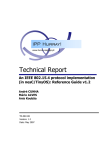
File Hierarchy
The Chipcon MAC source code folder hierarchy is shown in Figure 1 below.
Table 7 describes the files included in the CC2420 / ATMEGA128 / CC2420DB HAL library.
Table 8 describes the files/modules included in the MAC layer.
Table 9 lists the examples (demo applications) included in this release.
Chipcon AS SmartRF® CC2420 IEEE 802.15.4 MAC / PHY Software Layers, revision 0.7
Page 21 of 33
SmartRF ® CC2420
Figure 1. Folder Hierarchy
5.12.1. HAL - Hardware Abstraction Layer
Header files (*.h) are located in include\hal\atmega128, unless specified otherwise.
Source files (*.c) are located in lib\hal\atmega128, unless specified otherwise.
Filename
Description
hal.h
Hardware abstraction layer for the ATMEGA128(L) MCU.
include\hal\hal_cc2420.h
CC2420 register and RAM definitions + additional useful
constants and macros.
hal_cc2420db.h
Constants and macros that are specific for the CC2420DB
development platform (see section 6.1)
hal_stk501.h
Constants and macros that are specific for the CC2420DB
development platform (see section 6.3)
hal_rf_wait_for_crystal_oscillator.c
This file contains a function for polling the crystal oscillator until
it has started (is stable).
hal_wait.c
This file contains a function for idle looping a specific number of
microseconds.
hal_write_eeprom.c
These files contain functions that can be used to program a 64bit IEEE address into the integrated ATMEGA128 EEPROM.
The EEPROM read function can for instance be added to the
MAC_INIT() macro in mac.h, to initialize the aExtendedAddress
variable.
hal_read_eeprom.c
Table 7. HAL Source Code Files
5.12.2. MAC library
Header files (*.h) are located in include\mac\atmega128, unless specified otherwise.
Source files (*.c) are located in lib\mac\atmega128, unless specified otherwise.
Chipcon AS SmartRF® CC2420 IEEE 802.15.4 MAC / PHY Software Layers, revision 0.7
Page 22 of 33
SmartRF ® CC2420
Filename
Description
mac.h
mac.c
This module contains the MLME and MCPS primitives, and all
types and constants to be used with them.
mac_beacon_handler.h
mac_beacon_handler.c
This module contains functions used to transmit and receive
(track) beacons, and related functions, such as
synchronization and coordinator realignment.
mac_headers.h
This is the master header file, which is included in all MAC
source files, and should also be included by the higher layer.
mac_indirect_polling.h
mac_indirect_polling.c
This module contains functions related to indirect packet
polling, including packet formatting (data request command
frame) and timeouts.
mac_indirect_queue.h
mac_indirect_queue.c
This module contains functions related to the indirect packet
queue (on coordinators), including queue management,
transmission initiation, expiration, and other functions.
mac_general.h
mac_general.c
This module contains general types, constants, macros and
functions used by many other MAC modules.
mac_power_management.h
mac_power_management.c
This module contains functions to be used by the higher layer
to power down the CC2420.
mac_rx_engine.h
mac_rx_engine.c
This module contains the MAC RX engine (FIFOP interrupt),
including packet processing functions, and functions to control
the RX state (on/off...)
mac_rx_pool.h
mac_rx_pool.c
This module contains the RX packet pool, which manages a
table of MAC_RX_PACKET structures to be used with the RX
engine.
mac_scan.h
mac_scan.c
This module contains the scan state machine, and transmission
of scan-related packets.
mac_scheduler.h
mac_scheduler.c
This module contains the task scheduler used by the MAC
layer. A task can be started at every backoff slot boundary,
assuming that no tasks of same or higher priorities running
mac_security.h
mac_security.c
This file contains functions for finding and setting up security
and ACL related material.
mac_setup.h
This file contains the MAC setup parameters which may be set
differently for different applications or devices. These
parameters can also be set in the make file.
mac_support.h
mac_support.c
This module contains support/utility functions for the MAC
sublayer.
mac_timer.h
mac_timer.c
This module contains the MAC callback timer, which is used to
handle timer events, and execution of tasks.
mac_tx_engine.h
mac_tx_engine.c
This module contains the MAC TX engine, which is used to
transmit all RF packets.
mac_tx_pool.h
mac_tx_pool.c
This module contains the TX packet pool, which manages a
table of MAC_TX_PACKET structures to be used with the TX
engine.
Table 8. MAC Source Code Files
5.12.3. Examples of Usage
Filename
Description
apps/mac/mac_blink_led/mac_blink_led.c
apps/mac/mac_blink_led/makefile
Sample program 01, see section 9.1
apps/mac/mac_rf_modem/rf_modem.c
apps/mac/mac_rf_modem/makefile
Sample program 02, see section 9.2
Table 9. MAC Example Code Files
Chipcon AS SmartRF® CC2420 IEEE 802.15.4 MAC / PHY Software Layers, revision 0.7
Page 23 of 33
SmartRF ® CC2420
6. Hardware Platforms
The Chipcon IEEE 802.15.4 MAC layer may be run on different hardware platforms. The
included C source code is written for an Atmel ATmega 128(L). Porting the MAC layer to
other microcontroller platforms is allowed under the MAC software licensing agreement.
The following sections describe different options for setting up IEEE 802.15.4 nodes using the
CC2420 and different hardware platforms.
6.1. CC2420DK and Atmel STK500 / STK501
The CC2420DK includes two evaluation modules (CC2420EM, containing the CC2420 RF
chip) and two evaluation boards (CC2400EB, used to connect the CC2420EM module).
The CC2420DK may be used together with the Atmel AVR STK500 / STK501 development
kit to prototype an IEEE 802.15.4 application. The two boards are connected together through
a ribbon cable, as described below.
The FPGA file for MCU interfacing, downloadable from the Chipcon website, must be
programmed into the CC2400EB board using SmartRF Studio (select the board and push
“Load FPGA Configuration”) to allow access to the CC2420 pins from the microcontroller. The
USB connection to the PC may (optionally) be disconnected once the FPGA file is uploaded.
Set the HARDWARE_PLATFORM parameter in the makefile to STK501 to use this hardware
platform.
The current release will only support CC2420 chip revisions with date code 0411 (11th week
in 2004) or later. This is because of the new IOCFG0.BCN_ACCEPT control bit. All
CC2420DB boards (described in section 6.3) have this chip revision.
Chipcon AS SmartRF® CC2420 IEEE 802.15.4 MAC / PHY Software Layers, revision 0.7
Page 24 of 33
SmartRF ® CC2420
The hardware setup requirements for two IEEE 802.15.4 units is listed in the table below.
Needed # of items
Item
Each of which contain
1
Chipcon CC2420DK
2 pcs CC2400EB,
2 pcs CC2420EM,
2 pcs SMA Antennas,
4 pcs SMA to BNC adapters
2 pcs USB cable
5 pcs CC2420 samples
2
Atmel AVR STK500
1 pcs STK500 starter kit evaluation board
2 pcs 10-wire cables for I/O ports and parallel mode programming
1 pcs 6-wire cable for In-System Programming
4 pcs 2-wire cable for UART and DataFlash connections
1 pcs 9-pin RS-232 cable
1 pcs DC power cable
1 pcs AT90S8515-8PC sample microcontroller (not used for MAC)
Documentation / software
2
Atmel AVR STK501
1 pcs plugin module for STK500
1 pcs Atmega 128(L) (used by the MAC)
connectors / jumpers
2
DC Power supplies for
Chipcon CC2420DK
4–7V
2
DC Power supplies for
Atmel AVR STK500
10 – 15 V, as specified by Atmel
2
20-wire ribbon cable
and connectors
2
8 MHz crystals
40 ppm or better (including temperature / ageing)
1 (optional, for
debugging)
Atmel JTAG ICE
JTAG Programming and debugging interface
1 (optional, for
debugging)
DC Power supply for
Atmel JTAG ICE
9 – 15 V DC or 9 V AC, as specified by Atmel
Table 10. CC2420DK and Atmel ATSTK500 hardware setup requirements
Chipcon AS SmartRF® CC2420 IEEE 802.15.4 MAC / PHY Software Layers, revision 0.7
Page 25 of 33
SmartRF ® CC2420
The connection between the CC2400EB and the STK500 boards is described in Table 11
below.
Test Port 1 Pin Number
Test Port 1 (to / from uC)
Connection to STK500
1
N/C
2
N/C
3
N/C
4
FIFOP (to uC)
PD0
5
HighZ
PD1
6
HighZ
PD2
7
HighZ
PD3
8
SFD (to uC)
PD4
9
HighZ
PD5
10
HighZ
PD6
11
HighZ
PD7
12
CSn (from uC)
PB0
13
SCLK (from uC)
PB1
14
SI (from uC)
PB2
15
SO (to uC)
PB3
16
CCA (to uC)
PB4
17
FIFO (to uC)
PB5
18
RESETn (from uC)
PB6
19
VREG_EN (from uC)
PB7
20
GND
GND
Table 11. CC2400EB / STK500 connections
The sample programs included with the MAC source code additionally requires physical
connections listed in Table 12 made on the STK500 / STK501 boards. These apply to the
software examples only, and does not apply to the MAC source code in the general case.
STK500 / STK501 pin
STK500 / STK501 pin
Reason for connection
PCx (STK500)
LEDSx (STK500)
Connect all 8 LEDs on STK500 to port C
PAx (STK500)
SWx (STK500)
Connect all 8 switches on STK500 to port A
Table 12. STK500 / STK501 connections for MAC software examples
Using the hardware setup in this section may cause instability of the MAC source code
caused by glitches on the ribbon cable. The preferred hardware platform is therefore the one
described in section 6.3.
6.2. CC2420DK and other microcontrollers
The CC2420DK hardware platform may be connected to any other microcontroller
development environment in much the same way as described in section 6.1. It is highly
recommended to connect the CC2420 SPI pins to a hardware SPI interface on the interfacing
microcontroller.
Chipcon AS SmartRF® CC2420 IEEE 802.15.4 MAC / PHY Software Layers, revision 0.7
Page 26 of 33
SmartRF ® CC2420
The pin mapping between the CC2400EB board (containing the CC2420EM plugin module)
and the microcontroller development kit must be defined such that all pins listed in Table 11
are connected properly to a pin on the host microcontroller.
See section 7.2 for more information on porting the MAC layer to other microcontrollers.
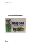
6.3. CC2420DB
The Chipcon CC2420DBK includes the two CC2420DB boards with a CC2420 RF transceiver
together with an Atmel AVR microcontroller and peripherals on a single board. This hardware
platform is available from Chipcon. A picture of a CC2420DB board can be seen in Figure 2
below. Please see the Chipcon website [2] for more details, where full schematics and
documentation is available.
Set the HARDWARE_PLATFORM parameter in the makefile to CC2420DB to compile for this
hardware platform.
Figure 2. CC2420DB picture
Hardware requirements when using the CC2420DBK is listed in Table 13 below.
Needed # of items
Item
Each of which contain
1
Chipcon CC2420DBK
2 pcs CC2420DB
1 pcs Quick Start instructions
1 pcs CC2420 sample kit
2 pcs RS-232 cables
2
DC Power supplies for
Chipcon CC2420DBK
4 – 7 V DC power supply
1 (optional, for
debugging)
Atmel JTAG ICE
JTAG Programming and debugging interface
1 (optional, for
debugging)
DC Power supply for
Atmel JTAG ICE
9 – 15 V DC or 9 V AC, as specified by Atmel
Table 13. CC2420DBK hardware setup requirements
The CC2420DB boards may also be run off 9V batteries attached to the backside battery
connector.
Chipcon AS SmartRF® CC2420 IEEE 802.15.4 MAC / PHY Software Layers, revision 0.7
Page 27 of 33
SmartRF ® CC2420
Although CC2420 is the lowest power consumption IEEE 802.15.4 RF transceiver in the
market today, the CC2420DB boards do not provide the optimal low current consumption
required for some battery powered applications. Please see section 5.4 for some
suggestions.
7. MAC Software Modifications
7.1. Optimizing the MAC layer
The MAC layer may be optimized for parameters such as performance, code size, RAM size
and power consumption. This can be done on an application to application basis. For
example parameters which are fixed in the application may be removed from the MAC layer
functions, variables which are not used may be removed and so on.
However, care should of course be taken when modifying the MAC source code, not to
introduce any bugs.
7.2. Porting the MAC to another microcontroller
Porting the MAC software layer to another microcontroller will require a significant amount of
work. Issues which must be particularly looked into and verified are:
•
The timing engine in the current MAC uses TIMER1 to generate interrupts every 20
symbol periods (320 µs). This timing engine must be re-written. The interrupt service
routine should focus on low execution time to reduce the performance overhead.
•
Interrupt handling is complex and requires that interrupts are periodically disabled.
The current MAC disables the global interrupt flag. Selective interrupt disabling may
be chosen for a porting of the MAC layer. It is important that the timing engine is
allowed to perform ticks every 20 symbol periods.
•
The processing power must be sufficient to handle any events generated from the
higher layers.
•
Byte ordering (endianess) must be particularly looked into if the chosen
microcontroller / compiler is big-endian. The current MAC requires little-endianess.
Some functions and data types utilize the fact that data is stored little-endian, this
particularly applies to data which is communicated to and from the CC2420 RF
transceiver.
8. Software Platforms
This section contains information on the compiler / debugger recommendations from Chipcon
for the hardware platforms described in 6.1 and 6.3, which are both based on Atmel AVR
microcontrollers.
For 8051 based systems, some recommendations are available from the Chipcon website.
For other hardware platforms (e.g. using a microcontroller from another provider than Atmel),
the compiler and debugger should be chosen following an evaluation of the performance and
features of these tools.
Chipcon AS SmartRF® CC2420 IEEE 802.15.4 MAC / PHY Software Layers, revision 0.7
Page 28 of 33
SmartRF ® CC2420
8.1. Compiler
The Chipcon CC2420 MAC software is compiled using the free AVR-GCC compiler:
http://www.avrfreaks.net/AVRGCC/
This release is compiled using version 3.4.1 of AVR-GCC.
8.2. Debugger
Chipcon uses the Atmel AVR Studio for Flash programming / debugging:
http://www.atmel.com/dyn/products/tools_card.asp?tool_id=2725
Debugging requires the Atmel JTAG ICE.
9. MAC Examples
This section describes the demonstration software examples included with the Chipcon MAC
layer. The descriptions below can also be found in the beginning of the application source
files, with more details about LEDs and buttons.
9.1. CC2420DB LED-Blinker Demo ("Knight Rider")
INTRODUCTION: This application demonstrates how to establish a beacon or non-beacon
PAN, how a device will scan for coordinators and associate on the PAN, and data traffic in
both directions (indirect packets from the coordinator, direct packets from the device).
This demo requires two CC2420DBs or CC2420DK and Atmel STK500 / STK501 setups, as
described in section 6.
INSTRUCTIONS: One device will act as the PAN coordinator. For this device:
•
Press the joystick center button down to create a non-beacon PAN.
•
Move the joystick in any direction to create a beacon-enabled PAN with beacon and
superframe order 4.
The other device will attempt to associate on the network after performing an active scan. For
this device:
•
Press S2 (red button) to start scanning (the coordinator must be up and running). S2
can be pressed again later on to disassociate.
A LED will walk back and forth between the two CC2420DB in a repeating pattern, controlled
by first byte in the data frames transmitted by the device:
Coord
LED
Device
Coord
Device
G-O-R-Y -> G-O-R-Y-R-O-G -> Y-R-O-G-O-R-Y -> G-O-R-Y
pMsdu[0] 0 1 2 3
4 5 6 7 6 5 4
3 2 1 0 1 2 3
Chipcon AS SmartRF® CC2420 IEEE 802.15.4 MAC / PHY Software Layers, revision 0.7
4 5 6 7
Page 29 of 33
SmartRF ® CC2420
9.2. 802.15.4 RF modem for CC2420DB
INTRODUCTION: This file implements a RF modem, which can replace a serial cable
between two computers. A coordinator is started for a non-beacon network, and a single
device is allowed to associate on it. Both nodes use short addresses (assigned by the
coordinator). The modem is default set up on channel 26 (0x1A). The channel assignment
may easily be changed in the source code.
Two ring buffers are used between the UART and the MAC layer interface, one for each
direction. The baudrate is set to 19200 bauds with one stop bit, no parity and hardware flow
control. Data transfers work as follows:
From PC:
•
UART -> buffer:
o
•
SIGNAL(SIG_UART1_RECV) transfers one byte per interrupt
buffer -> MAC/RF:
o
main() calls to mcpsDataRequest(...) to transmit a packet (n bytes)
o
mcpsDataConfirm(...) notifies main() when the transmission has
finished
To PC:
•
RF/MAC -> buffer:
o
•
mcpsDataIndication is called when a packet has been received (n bytes)
buffer -> UART:
o
SIGNAL(SIG_UART1_DATA) transfers one byte per interrupt
This demo requires two CC2420DBs.
It is also possible to run the example to run on the CC2420DK and Atmel STK500 / STK501
platform. If so, the RS232 spare #2 port should be used, since this is the only one with
hardware flow control. Switch button 0 is used in stead of S2 and Switch button 1 is used in
stead of the joystick center button.
INSTRUCTIONS: One device will act as the PAN coordinator. For this device:
•
Press S2 (red button) down to create a non-beacon PAN.
The other device will attempt to associate on the network after performing an active scan. For
this device:
•
Press the joystick center button to start scanning (the coordinator must be up and
running).
Manual power saving is also illustrated in this example. Press the joystick down to go to sleep
and press joystick up to wake up again. This will put the CC2420 transceiver in full sleep,
where less than 1 uA current is drawn. The rest of the CC2420DB board will still draw a
higher current, since the microcontroller is not put into sleep in this example. For a specific
Chipcon AS SmartRF® CC2420 IEEE 802.15.4 MAC / PHY Software Layers, revision 0.7
Page 30 of 33
SmartRF ® CC2420
application it is however possible to let the microcontroller sleep and wake up on external or
low-power timer events.
10. MAC Software Limitations / Bugs
The limitations / bugs known on this revision of the MAC software are listed in Table 14. Any
bugs / update requests should be reported to [email protected]
For future updates from IEEE 802.15.4b, please visit www.ieee802.org/15/pub/TG4b.html.
Mailing lists are open. Further information, including IEEE 802.15.4-2003 comments
database, is also openly available at http://www.802wirelessworld.com
Function
Status
Future Plans
GTS
Not implemented
May be implemented upon customer requests.
Power
optimization
Not fully implemented, see section .
May be further developed upon customer requests.
Dynamic CCA
level
Not implemented. The level defining when
the channel is clear is currently static.
May be implemented depending on customer
requirements.
Acknowledge
frame timing
Timing of acknowledge frames in beacon
networks does not align to the backoff slot
boundaries
May be implemented upon customer requirements.
This is a microcontroller resource issue.
Sequential
freshness
Not implemented
This feature will be updated in later revisions.
Secure beacons
The current revision of the MAC does not
support secure beacons, i.e.
mlmeStartRequest must be called with
the securityEnable parameter set to
FALSE.
This feature will be updated in later revisions.
Security
The current revision of the MAC contains
software non-conformances and errors with
respect to security. There are multiple
issues with the security specification of
IEEE 802.15.4-2003 which are being
revised by 802.15.4b
This feature will be updated in later revisions.
mlme-rxenable.request
in beacon
networks
The mlme-rx-enable.request primitive
should only be used with non-beacon
networks. For beacon networks, use the
RX on when idle PIB in stead.
May be implemented upon customer requirements.
Data Request
command
frames
Data request command frames always
have a destination address even if
transmitted to the PAN coordinator.
IEEE 802.15.4b plan on allowing this behaviour
Disassociation
with a short
device
MAC is implemented according to [1], but
disassociation from the coordinator with
the device having a short address does not
work
IEEE 802.15.4b will make updates on this
behaviour.
Transaction
persistence
time
The current MAC release has a maximum
value for the
MAC_TRANSACTION_PERSISTENCE_TIME
pib attribute value of 32767 (in stead of the
maximum of 65535 specified in [1])
This feature will be updated in later revisions.
Code Size
Optimization
The MAC / PHY Sublayer is not yet fully
code size optimized.
Will be continuously improved.
Table 14. CC2420 MAC Software Limitations / known bugs
Chipcon AS SmartRF® CC2420 IEEE 802.15.4 MAC / PHY Software Layers, revision 0.7
Page 31 of 33
SmartRF ® CC2420
General Information
Product Status Definitions
Data Sheet Identification
Product Status
Definition
Advance Information
Planned or Under
Development
This data sheet contains the design specifications for
product development. Specifications may change in
any manner without notice.
Preliminary
Engineering Samples
and First Production
This data sheet contains preliminary data, and
supplementary data will be published at a later date.
Chipcon reserves the right to make changes at any
time without notice in order to improve design and
supply the best possible product.
No Identification Noted
Full Production
This data sheet contains the final specifications.
Chipcon reserves the right to make changes at any
time without notice in order to improve design and
supply the best possible product.
Obsolete
Not In Production
This data sheet contains specifications on a product
that has been discontinued by Chipcon. The data
sheet is printed for reference information only.
Disclaimer
Chipcon AS believes the information contained herein is correct and accurate at the time of this printing. However,
Chipcon AS reserves the right to make changes to this product without notice. Chipcon AS does not assume any
responsibility for the use of the described product; neither does it convey any license under its patent rights, or the
rights of others. The latest updates are available at the Chipcon website or by contacting Chipcon directly.
As far as possible, major changes of product specifications and functionality, will be stated in product specific Errata
Notes published at the Chipcon website. Customers are encouraged to sign up to the Developers Newsletter for the
most recent updates on products and support tools.
When a product is discontinued this will be done according to Chipcon’s procedure for obsolete products as
described in Chipcon’s Quality Manual. This includes informing about last-time-buy options. The Quality Manual can
be downloaded from Chipcon’s website.
Trademarks
SmartRF® is a registered trademark of Chipcon AS. SmartRF® is Chipcon's RF technology platform with RF library
cells, modules and design expertise. Based on SmartRF® technology Chipcon develops standard component RF
circuits as well as full custom ASICs based on customer requirements and this technology.
All other trademarks, registered trademarks and product names are the sole property of their respective owners.
Life Support Policy
This Chipcon product is not designed for use in life support appliances, devices, or other systems where malfunction
can reasonably be expected to result in significant personal injury to the user, or as a critical component in any life
support device or system whose failure to perform can be reasonably expected to cause the failure of the life support
device or system, or to affect its safety or effectiveness. Chipcon AS customers using or selling these products for
use in such applications do so at their own risk and agree to fully indemnify Chipcon AS for any damages resulting
from any improper use or sale.
© 2004, Chipcon AS. All rights reserved.
Chipcon AS SmartRF® CC2420 IEEE 802.15.4 MAC / PHY Software Layers, revision 0.7
Page 32 of 33
SmartRF ® CC2420
Address Information
Web site:
E-mail:
Technical Support Email:
Technical Support Hotline:
http://www.chipcon.com
[email protected]
[email protected]
+47 22 95 85 45
Headquarters:
Chipcon AS
Gaustadalléen 21
NO-0349 Oslo
NORWAY
Tel: +47 22 95 85 44
Fax: +47 22 95 85 46
E-mail: [email protected]
US Offices:
Chipcon Inc., Western US Sales Office
19925 Stevens Creek Blvd.
Cupertino, CA 95014-2358
USA
Tel: +1 408 973 7845
Fax: +1 408 973 7257
Email: [email protected]
Chipcon Inc., Eastern US Sales Office
35 Pinehurst Avenue
Nashua, New Hampshire, 03062
USA
Tel: +1 603 888 1326
Fax: +1 603 888 4239
Email: [email protected]
Sales Office Germany:
Strategic Automotive Center:
Chipcon AS
Riedberghof 3
D-74379 Ingersheim
GERMANY
Tel: +49 7142 9156815
Fax: +49 7142 9156818
Email: [email protected]
Chipcon AS
Hechtseestrasse 16D-83022
Rosenheim
GERMANY
Tel: +49 8031 2227 660
Fax: +49 8031 2227 661
Email: [email protected]
Sales Office Asia :
Chipcon Asia Pasific
37F, Asem Tower
159-1 Samsung-dong, Kangnam-ku
Seoul 135-798 Korea
Tel: +82 2 6001 3888
Fax: +82 2 6001 3711
Email: [email protected]
Chipcon AS is an ISO 9001:2000 certified company
Chipcon AS SmartRF® CC2420 IEEE 802.15.4 MAC / PHY Software Layers, revision 0.7
Page 33 of 33