1
Using DMAC II with Chained Transfer
R32C/100 Series
(1) Initial setting
(2) First DMAC II request (INT0 interrupt) generated
00001000h
0086h
0002h
00002000h
00002800h
00001400h
MOD
COUNT
SADR
DADR
CADR
00001000h
0086h
0001h
00002001h
00002800h
00001400h
00001400h
0086h
0002h
00003000h
00003800h
00001800h
MOD
COUNT
SADR
DADR
CADR
00001400h
0086h
0002h
00003000h
00003800h
00001800h
00002000h
00002001h
11h
22h
00002000h
00002001h
11h
22h
00002800h
XXh
00002800h
11h
00003000h
00003001h
FFh
EEh
00003800h
XXh
00003000h
00003001h
FFh
EEh
00003800h
XXh
INT0 interrupt vector (1)
When DMA II transfer starts,
the DMAC II index setting
allocated to address
00001000h is used for
operation.
INT0 interrupt vector (1)
00001000h
(3) Second DMAC II request
(INT0 interrupt) generated
00001000h
0086h
0000h
00002002h
00002800h
00001400h
MOD
COUNT
SADR
DADR
CADR
00001400h
0086h
0002h
00003000h
00003800h
00001800h
MOD
COUNT
SADR
DADR
CADR
00002000h
00002001h
11h
22h
DMA II
transfer
00002800h
(4) Third DMAC II request
(INT0 interrupt) generated
00001000h
0086h
0000h
00002002h
00002800h
00001400h
MOD
COUNT
SADR
DADR
CADR
00001400h
0086h
0001h
00003001h
00003800h
00001800h
MOD
COUNT
SADR
DADR
CADR
When COUNT is 0, the
value of the DMA II transfer
trigger interrupt vector is
overwritten with the CADR
value.
11h
22h
22h
00002800h
22h
00003000h
00003001h
FFh
EEh
00003000h
00003001h
FFh
EEh
00003800h
XXh
00003800h
FFh
00001400h
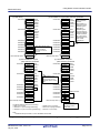
The above diagram assumes the following:
• SIZE bit is 0 (8 bits)
• UPDS bit is 1 (incrementing addressing)
• UPDD bit is 0 (non-incrementing addressing)
After performing a
DMA II transfer,
COUNT
decrements by 1.
When the source
addressing and
destination
addressing are
MOD
COUNT incrementing, the
SADR and DADR
SADR
values increment
DADR
by 1 and 2 when
CADR
transferring 8 bits
and 16 bits,
respectively.
DMA II
transfer
00001000h
00002000h
00002001h
INT0 interrupt vector (1)
MOD
COUNT
SADR
DADR
CADR
INT0 interrupt vector (1)
• OPER bit is 0 (not used)
• BRST bit is 0 (single transfer)
• INTE bit is 0 (not used)
DMA II transfer
00001400h
Operated using the
DMAC II index setting
allocated to address
00001400h
Note:
1. Software interrupt number 31 in the relocatable vector table.
Figure 3.1
Operation Example of Chained Transfer Using an INT0 Interrupt to Trigger DMAC II
REJ05B1415-0100 Rev.1.00
July 30, 2010
Page 3 of 14