1
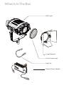
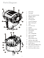
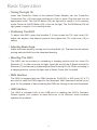
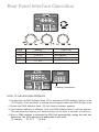
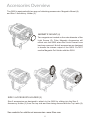
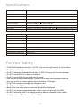
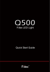
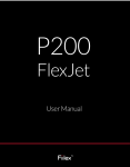
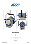
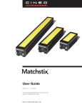
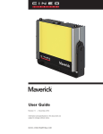
Q500DC
Fiilex LED Light
Quick Start Guide
Table of Contents
What Is In The Box
1
Parts Diagram
2
Basic Operation
3
Rear Panel Interface Operation
4
Accessories Overview
5
Specifications
6
For Your Safety
6
What Is In The Box
• Q500 Light
• 4 Leaf Barndoor
• 5-Inch Fresnel Lens
• Cable Tie
• External Power Adapter
1
Parts Diagram
1
11
2
3
10
4
5
9
6
7
8
13
12
14
23
1
Vent Holes
2
Top Latch
3
Size 3 Accessory Holder
4
Magnetic Mount
5
Light Source
6
Focusing Knob
7
Junior Pin Receiver
8
Stand Locking Pin
9
Yoke
10
Tilt Lock Lever
11
Handles
12
DMX Address Knob
13
LCD Display
14
Yoke Bolt
15
CCT Tuning Knob
16
HUE Tuning Knob
17
DMX Output
(XLR -Female 5-Pin)
15
16
22
17
18
19
21
20
2
18
USB Port (Mini USB)
19
PowerCon Connection Port
20
On/Off Button
21
DMX Input (XLR-Male 5-Pin)
22
In te n si ty Co n tr o l K n o b
23
RJ45 Ports (DMX In/Out)
Basic Operation
• Turning The Light On
Insert the PowerCon Cable of the external Power Adapter into the PowerCon
Connection Port (19) and rotate clockwise to lock in place. Plug the light into an
appropriate outlet. The On/Off Button (20) will light red to signify it is in stand-by
mode. Press the On/Off Button (20) to turn on the light. The On/Off Button (20) will
light green to signify it is in working mode.
• Positioning The Q500
To adjust the Q500, grasp the Handles (11) then loosen the Tilt Lock Lever (10).
Adjust the angle to the desired position then tighten the Tilt Lock Lever (10) to
secure.
• Adjusting Beam Angle
Adjust the beam angle by turning the Focusing Knob (6). The lens tube will extend,
moving back and forth from the lamphead housing.
• Mounting The Q500
The Q500 can be mounted in a standing or hanging position with the Junior Pin
Receiver (7). In order to mount the light, insert the stud of the C-Stand into the Pin
Receiver (7) and secure by tightening the Stand Locking Pin (8). When mounting in
a hanging position, secure the light with a Safety Cable (Not Included).
• DMX Interface
The Q500 is equipped with two DMX interfaces. RJ45 (23) or XLR ports (21 & 17)
are used to send the DMX signal to the lamphead. Both interfaces include in/out
ports for the purpose of daisy-chaining the DMX line through to the next lamphead.
• USB Interface
The Q500 is equipped with a mini USB port for updating the Q500's firmware.
Please register your product at www.fiilex.com to be informed when firmware
updates are available.
3
Rear Panel Interface Operation
KNOB
CCT
PWR
HUE
DMX
RANGE
2800K~6500K
100%-5%
± .25 Magenta / Green
0 ~ 512
Set
Set
Set
Set
FUNCTION
color temperature
intensity
HUE value
DMX address
Flashing underscore
HOW TO ASSIGN DMX ADDRESS:
1. Double click the DMX Address Knob (12) to activate the DMX Address Section of the
LCD Display. Once activated, a blinking line will appear below the DMX Display Area.
2. Rotate the DMX Address Knob (12) until desired address appears.
3. Once desired address is selected, click the DMX Address Knob to set the address.
The new selected address will automatically be set after 3 seconds of inactivity.
4. When a DMX address is selected the Q500 will automatically assign the next two
addresses.The Q500 assigns the addresses in this order:
(1) Intensity
(2) CCT
(3) Hue
4
Accessories Overview
The Q500 is equipped with two ways of attaching accessories: Magnetic Mount (4)
and Size 3 Accessory Holder (3).
MAGNETIC MOUNT (4)
Two magnets are located on the outer diameter of the
Light Source (5). Fiilex Magnetic Accessories will
mount onto the Q500 when the 5-inch Fresnel Lens
has been removed. Not all accessories are designed
to handle the intense output of the Q500. Do NOT
use the Magnetic Gel Holder with the Q500.
SIZE 3 ACCESSORY HOLDER (3)
Size 3 accessories are designed to attach to the Q500 by sliding into the Size 3
Accessory Holder (3) from the top side and then being secured with the Top Latch (2).
See website for additional accessories. www.fiilex.com
5
Specifications
Size (without Barndoor)
305mm X 325mm x 380mm (With yoke)
Weight (Includes Yoke)
15.8 lbs / 7.2 kg
LED
Dense Matrix LED
Thermal Design
Advanced Vapor Cooling
CCT Range
2800-6500K Continuous Tuning
CRI
>93 (3000-5600k)
Power Consumption
AC Power 185W Max
Power Connection
Detachable PowerCon Cable
DC Power 170W Max
Input Voltage
AC Power: 100-240V AC, 50~60Hz, Max 185W
Operating Temperature
32-104ºF / 0-40º C (Over Temperature Protection)
Beam Angle
27°-50° (With 5” Fresnel Lens)
DC Power: 20-50V DC, Max 170W
Lens Diameter
130mm / 5 inch
Mounting
Baby Stud 5/8" Female (16mm) and Junior Stud 1-1/8" Male (28mm)
Tilt Angle
+/- 90°
Control
DMX, 512 Addresses, XLR5, RJ45
Mini USB Interface
For Firmware Upgrades
Housing Colors
Black
Protection Class
IPX4, Waterproof
Estimated LED Lifetime (L70)
50,000 Hours
Certifications
CE, UL, FCC
For Your Safety
• CAUTION! High Beam Intensity! - Do NOT look into the Light Source (5) of the fixture.
• Do NOT point the light at combustible or flammable materials.
• Do NOT attempt to disassemble the body of Q500. Doing so will void the warranty.
• Do NOT install Q500 in a damp or wet area.
• Do NOT cover/block the side and back air vents.
• Use only the included power supply. Failure to do so may cause damage to the light.
• Use only a soft, dry towel to gently clean the exterior of the light.
• Do NOT lift or suspend the light by the power cable.
• Do NOT use the Q500 or accessories if they display any physical damage.
• Before first use, make sure to remove all protective membranes.
• Do NOT use the gel holder designed for the P series of lights with the Q500.
• Do NOT mount the Q500 in a hanging position without a separate safety cable.
A safety cable is NOT included with the Q500.
6
Any product, unit, or part returned to Fiilex must be packaged in a suitable
manner to ensure the protection of such product, unit, or part. The package
must be clearly and prominently marked with a Return Merchandise
Authorization Number (RMA #) to indicate that the package contains returned
products, units, or parts. All returned products, units, or parts must be
accompanied by a written explanation of the alleged problem or malfunction.
7
Fiilex.com
1689 Regatta Blvd., Richmond, CA 94804
(510)-620-5155 | [email protected]
Information and Specifications in this document are subject to change without notice. DiCon Lighting, Inc. assumes no responsibility or
liability for any error or inaccuracies that may appear in this manual. Unlawful reproduction or distribution in any manner without the
written permission of DiCon Lighting, is strictly prohibited.
© DiCon Lighting 1996-2015. All rights reserved.
8