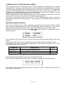
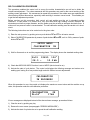
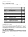
1
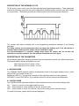
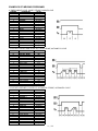
LORS / 1090 LOUSONS ROAD ♦ UNION, NEW JERSEY 07083 USA Tel: 908-964-9100 ♦ Fax: 908-964-4492 ♦ email: [email protected] WELDING CONTROL UNIT: TE 450 USER MANUAL RELEASE SOFTWARE No. 1.50 DOCUMENT NUMBER: MAN 4097 EDITION: MARCH 1998 TABLE OF CONTENTS SUBJECTS PAGE WELDING CONTROL UNIT TE450 3 PROGRAMMING THE CONTROL UNIT 4 DESCRIPTION OF THE WORKING CYCLE 7 DESCRIPTION OF THE PARAMETERS 7 EXAMPLES OF WELDING PROGRAMS 11 WELDING CURRENT AND CONDUCTION ANGLE MEASURE 13 WELDING CURRENT AND CONDUCTION ANGLE LIMITS 14 CONSTANT CURRENT OPERATING MODE 15 STEPPER FUNCTION OPERATION 16 COMPENSATION OF THE SECONDARY CURRENT 20 -WELDING COUNTER FUNCTION 20 DOUBLE STROKE FUNCTION 21 USE OF THE "PRESSURE ONLY" CONTROL 22 "CHK" INPUT FUNCTION 23 THERMOSTAT INPUT FUNCTION 23 KEY SELECTOR FUNCTION (OPTIONAL) 23 SELF-CALIBRATION PROCEDURE 24 SET-UP MENU DESCRIPTION 25 ERRORS MESSAGES 27 ORDINARY AND EXTRAORDINARY MAINTENANCE 29 LAMPS ON THE CONTROL UNIT 30 SIGNAL DESCRIPTION ON CONNECTORS 30 2 / 33 WELDING CONTROL UNIT TE 450 TE450 is a microprocessor welding control unit for suspended resistance welding guns. The welding control unit is used to control the welder parts, and in particular the thyristors adjusting the welding current. This control unit includes specific functions to be used when working with suspended welding guns, such as: double stroke control; control of the efficacy of the safety devices eventually installed on the handle of the machine. The handle is not a standard component of the welding control unit; it is possible to install different handles so to set the machine according to different working performances. It is possible to store up to 63 different welding programs; it is possible to directly recall 2 programs by means of an external selector commonly installed on the handle. Each program is formed by 18 adjustable parameters describing the working cycle. Besides the simple 4 times cycle, the control unit enables to carry out welding processes with pre-weld current, post-weld current, slope and pulses. TE450 can work in constant current mode, it displays the welding current and check the current according to the set limits. MAIN TECHNICAL DATA • • • • • • • • • • • • • • • • • Simplified programming by means of 5 push-buttons and LCD alphanumeric display. Synchronous thyristors drive with phase shift control for welding current adjustment. 63 welding programs to be stored up; 2 programs can be recalled from the handle. 18 programmable parameters for each program. Slope and pulse functions; pre-weld e post-weld functions. Welding times adjustment in half-periods. Display of both welding current in kA, and connected conduction angle. Double working mode: standard and constant current. Either welding current or conductor angle limits. Automatic double stroke function (to be employed only when the welder has been designed for this function). Stepper function to balance the electrodes wear-out with adjustable curve. Welds counter. Compensation of the secondary current to weld oxidized sheets and rods. Single and automatic cycle. WELD/NO WELD function. Delay of first phase shift adjustment to get the best balance of the machine absorption from mains. Control of 2 solenoid valves 24 Vac 7,2 W Max with protected output against short circuit: electrode closing valve and double stroke valve. Self-adjustment to the mains frequency 50/60 Hz. 3 / 33 PROGRAMMING THE CONTROL UNIT As soon as the welding control unit is turned on, the display shows the supply frequency and the version of the program. SUPPLY FREQUENCY 50 Hz. TE 450 REL. 1.50 WELD CONTROL After a few seconds, the TE450 is set in a waiting condition enabling to carry out the welding process. Pr01 12455 104° 08.0 ~ 12.3 kA Before starting the programming phase, it is important to learn some fundamental features of TE450. TE450 stores up 63 different welding programs. If the type of handle connected to the control units enables it, when working it is possible to quickly select two different programs respectively called "ADJUSTMENT 1" and "ADJUSTMENT 2". When working, the two adjustments are commonly carried out by means of a selector. For instance, when using the handle type 70838, the selection is carried out by means of selector no. 4. For each of the two adjustments, the welding program to be used is selected when programming. If the handle is not equipped with the selector enabling to select the two adjustments, the welding control unit always works in "ADJUSTMENT 1". The control unit shows all data and messages on a LCD display. The user can select the language of both warning and error messages. The programming parameters are always displayed in English. The programming is carried out by setting the parameters describing the welding cycle; select each parameter and set the required values one by one. To better understand the meaning of each parameter, read the relevant paragraph. To start the programming, push simultaneously the push-buttons ▲ and ▼ for at least a second; it is then possible to carry out the programming operations. After 8 seconds of inactivity, the control unit will automatically end the programming operation and enable the working process. 4 / 33 The first selection concerns the number of the program to be used for the adjustment in process. The adjustment selection ("ADJUSTMENT 1" or "ADJUSTMENT 2") is carried out by means of the proper selector (which is commonly a two-position selector placed on the handle). The program is selected by means of the push-buttons + e – . ADJUSTMENT 1 PROGRAM NUM. 34 After having selected the number of the program, it is possible to select the parameters forming the program by means of the push-buttons ▲ e ▼ . The parameters are marked either with a letter (from A to C) or a number (from 1 to 18). The display shows the following data: 1 2 3 ADJ1 PRG01 PRM07 WELD 1 08.0 ~ 4 1) 2) 3) 4) 5) 5 Selected adjustment (ADJ1=ADJUSTMENT 1 - ADJ2=ADJUSTMENT 2) Number of the selected program (PRG01= program number 1) Identification mark of the selected parameter Name of the parameter Value of the parameter The value of the welding parameters can be adjusted by means of the push-buttons + and – either increasing or decreasing the value shown by the display. The parameters can be adjusted to different values according to the type of parameter; the limits range for each parameter is given in the following table. PARAMETER NUMBER A B C 1 2 3 4 5 6 7 8 9 10 11 12 13 14 15 16 17 18 PARAMETER WORKING MODE CONTROL MODE STROKE SQUEEZE 1 SQUEEZE PRE-WELD PRE-POWER COLD 1 SLOPE UP WELD 1 POWER 1 CURRENT 1 N. IMPULSE COLD 2 SLOPE DOWN COLD 3 POST-WELD POST-POWER HOLD TIME OFF TIME CURR MIN ANGLE MIN CURR MAX ANGLE MAX 5 / 33 RANGE VALUE IK - PW% NO-CURR-DEG SHORT-LONG-AUTOMATIC 01 - 99 cycles 01 - 99 cycles 00.0 - 99.5 cycles 01 - 99% 00 - 50 cycles 00 - 25 cycles 00.5 - 99.5 cycles 10 - 99% 2.0 - 36.0 kA 00 - 09 01 - 50 cycles 00 - 25 cycles 00 - 50 cycles 00.0 - 99.5 cycles 01 - 99% 01 - 99 cycles 00 - 99 cycles 2.0 - 36.0 kA 001 - 180° 2.0 - 36.0 kA 001 - 180° There are some peculiar conditions: • If OFF TIME (16) is set to zero, the welding control unit will work in single cycle. • If OFF TIME (16) is set to 99, the welding control unit will carry out the min. current compensation with a value lower than 2.0 kA (see paragraph "COMPENSATION OF THE SECONDARY CURRENT") • By setting the PRE-WELD parameter (3) to zero, the pre-weld is not carried out. • By setting the POST-WELD parameter (13) to zero, the post-weld is not carried out. By following this procedure, it is possible to set all parameters to the required value in order to carry out the welding. Please, note that it is not necessary to press any push-button to confirm the set data, as each data is automatically stored up after the adjustment. When the programming operations are accomplished, wait until the control unit ends the programming phase; this takes automatically place after 8 seconds of inactivity. If the start of cycle device is activated before the control unit moves from the programming phase to the working phase, it will not be considered. Release the control device and start it again. Use the WELD/NO WELD function to carry out any test cycle without welding current. The welding current can be either enabled or disabled by means of the push-button here shown. When the lamp is on, the control unit is set to WELD: it carries out the standard welding cycles. When the lamp is off, the control unit is set to NO WELD: it carries out complete test-cycles, without welding current, even though all the time-parameters are preserved. When the control unit is set on a waiting condition, the display shows the following data: 1 2 3 Pr01 12455 104° 08.0 ~ 12.3 kA 4 1) 2) 3) 4) 5) 5 Selected welding program Number of the welds executed after the last counter reset The conduction angle of the last weld Set welding time Current value of the last weld As soon as the welding cycle is activated, the control unit checks the data of the selected program. An error message will be displayed if the values of the parameters are not compatible. Please refer to the welder user manual for the description of the control device functions. 6 / 33 DESCRIPTION OF THE WORKING CYCLE TE 450 working cycle is set by the user when adjusting the programming parameters. These parameters indicate the operating times and the current adjustments characterizing the working cycle when carried out consecutively. The following chart shows in which sequence the set functions are carried out. The numbers here above indicated refer to the programming parameters described in the following paragraph. For safety reasons, the microprocessor does not trigger the welding cycle if the start device is activated when switching on the welder; release it and start it again. Any microinterruptions or excessive voltage drops block the control and do not alter the operation; to reset the operation, turn the machine off and then turn it on again. DESCRIPTION OF THE PARAMETERS All the following parameters indicating a period of time are expressed in periods, also called mains cycles. The mains frequency defines the duration of a cycle. Mains frequency 50 Hz 1 period = 20 ms Mains frequency 60 Hz 1 period = 16.6 ms A - WORKING MODE The WORKING MODE parameter defines the adjustment mode of the program welding current: power percent (PW%) or constant current (IK). Welding time WELD 1 (7) is carried out according to the adjustment mode set in this parameter. PRE-WELD (3) and POST-WELD (13) are always carried out with the power percent adjustment. B - CONTROL MODE The CONTROL MODE parameter enables to select the desired control mode of the welding current. NO CUR DEG There is no control on the supplied welding current. TE450 enables to set the welding current min. and max. limits. TE450 enables to set the min. and max. limits of the welding current conduction angle For further information, please read the relevant paragraph. 7 / 33 C - STROKE (DOUBLE STROKE) TE 450 enables to control the double stroke (also called retraction) working on those machines equipped with this function. This parameter enables to define the double stroke desired working mode: SHORT Short stroke LONG Long stroke AUTOMATIC Automatically set stroke Additional data on this function are given in the relevant paragraph. This parameter can be set only if both the machine and the handle are designed for the control of the double stroke from the control unit. 1 - SQUEEZE 1 The SQUEEZE 1 time is used when working with the automatic double stroke. It determines the time employed by the electrode to shift from the long stroke to the short stroke position. The set value must be long enough to enable the mobile electrode to reach the short stroke position. During the SQUEEZE 1 time, it is possible to end the cycle if the start of cycle signal is deactivated. This parameter can be set only if both the machine and the handle are designed for the control of the double stroke from the control unit. 2-SQUEEZE The SQUEEZE time determines the electrodes closing time, that is to say the time interval elapsing between the beginning of the electrodes closing and the starting of the welding process. The set value must be long enough to have the electrodes reach both the piece to weld and the proper clamping force before the starting of the welding process. A too low adjustment of this time causes sparkles between electrodes and sheet when the welding process starts; it can also cause an unsteadiness of the welding quality. If the start cycle signal is deactivated during the squeeze time, the sequence is broken up. 3 - PRE-WELD The PRE-WELD parameter indicates the length of a current passage which can be carried out before the welding process so to pre-heat the piece to be welded. This parameter is indicated by three digits, as it can be set with a half-period precision. If this parameter is set to 0, the pre-weld will not be carried out. Pre-weld is carried out with a current adjustment equal to that stated on parameter 4 - PRE-POWER (PRE-WELD CURRENT). 4 - PRE-POWER (PRE-WELD CURRENT) The value expressed in this parameter indicates the power used to carry out the pre-weld. 5 - COLD 1 The COLD 1 parameter indicates the time elapsing between the pre-weld (3-PRE-WELD) and the weld (7WELD 1). If the pre-weld is deactivated (that is, when PRE-WELD = 0), this cooling time is not carried out. 6 - SLOPE UP The SLOPE parameter describes the time used to reach the programmed welding power value. The starting value of this slope always corresponds to the minimum power, while the final value corresponds to the value of power set to parameter 8-CURRENT (welding current). The slope speed is automatically calculated by the microprocessor according to the set values. SLOPE time is added to the welding time. 8 / 33 7 -WELD 1 The WELD 1 parameter indicates the current flow duration. It is carried out with the same power value set on parameter 8-CURRENT. When the pulse operating mode is activated, this parameter indicates the duration of each pulse. This parameter is expressed in three digits as it can be adjusted with the halfperiod precision. 8 - CURRENT 1 The value indicated in CURRENT 1 shows the current adjustment used to carry out the welding process. Depending on the working mode operation which has been selected by means of parameter AWORKING MODE, this value indicates either the current percent (PW%, power per cent adjustment), or the required current value expressed in-kA (IK, constant current adjustment). 9 - N. IMPULSE The N. IMPULSE parameter indicates the number of impulses used to carry out the welding process. The duration of each impulse corresponds to the time set on parameter 7-WELD1 (welding time). 10 - COLD 2 COLD 2 parameter is used with the pulse operating mode; it indicates the time elapsing between a welding impulse and the following one. 11 - SLOPE DOWN The SLOPE DOWN parameter is an additional welding time which is added at the end of the welding process: it enables to decrease the welding current from the value set on 8-CURRENT 1 to the minimum value. The slope speed is automatically calculated by the microprocessor according to the set values. 12 - COLD 3 The COLD 3 parameter indicates the time elapsing between the welding process (7-WELD 1) and the post-weld (13-POST-WELD). 13 - POST-WELD The POST-WELD parameter indicates the duration of a current passage which can be carried out after the welding time in order to enable a more gradual cooling of the welding spot. This parameter is indicated by three digits as it can be adjusted with the half-period precision. If this parameter is set to 0 the post-weld is not carried out. The post-weld is carried out with the current adjustment set on parameter 14-POST-POWER. 9 / 33 14 - POST-POWER The value expressed in this parameter indicates the post-welding power. 15 - HOLD TIME The parameter HOLD indicates the time elapsing between the end of the welding process and the opening of the electrodes. It allows a quicker cooling of the welding spot and prevents that the spot is moved before a proper cooling. 16-OFF TIME The OFF parameter indicates a machine waiting time, namely that elapsing between one machine cycle and the next one when the welder is working in automatic cycle. When this value is set to zero, the machine will go on working in single cycle; if it is set to another value, the machine will work in the automatic cycle. When the machine works in, single cycle, the control unit will carry out a single cycle each time it receives a start cycle signal. When the machine works in automatic cycle, the welder goes on executing welding cycles until the start cycle signal is released. By programming this parameter to 99 the welding current compensation function is activated (see the relevant paragraph). 17 - CURR MIN / ANGLE MIN (MINIMUM CURRENT LIMIT OR CONDUCTION ANGLE) This parameter expresses different data according to the control mode selected on parameter BCONTROL MODE. When the control is set to current control mode (CONTROL MODE=CUR), this parameter fixes a minimum current value. For each weld, the TE450 monitors that the welding current is higher than the limit set on this parameter; if it is lower, an error message will be displayed (see the relevant paragraph). When the control is set to degree control mode (CONTROL MODE=DEG), this parameter fixes a minimum conduction angle value. For each weld, the TE450 monitors that the welding current conduction angle is higher than the limit set on this parameter; if it is lower, an error message will be displayed (see the relevant paragraph). If the B-CONTROL MODE parameter is set to NO (no control on the welding current), the parameter is not displayed during the programming phase. 18 - CURR MAX / ANGLE MAX (MAXIMUM CURRENT LIMIT OR CONDUCTION ANGLE) This parameter expresses different data according to the control mode selected on parameter BCONTROL MODE. When the control is set to current control mode (CONTROL MODE=CUR), this parameter fixes a maximum current value. For each weld, the TE450 monitors that the welding current is lower than the limit set on this parameter; if it is higher, an error message will be displayed (see the relevant paragraph). When the control is set to degree control mode (CONTROL MODE=DEG), this parameter fixes a maximum conduction angle value. For each weld, the TE450 monitors that the welding current conduction angle is lower than the limit set on this parameter; if it is higher, an error message will be displayed (see the relevant angle). If the B-CONTROL MODE parameter is set to NO (no control on the welding current), the parameter is not displayed during the programming phase. 10 / 33 EXAMPLES OF WELDING PROGRAMS 4 TIMES SIMPLE CYCLE, SHORT STROKE, SINGLE CYCLE NUMBER A B C 1 2 3 4 5 6 7 8 9 10 11 12 13 14 15 16 PARAMETER WORKING MODE CONTROL MODE STROKE SQUEEZE 1 SQUEEZE PRE-WELD PRE-POWER COLD 1 SLOPE UP WELD 1 CURRENT 1 N. IMPULSE COLD 2 SLOPE DOWN COLD 3 POST-WELD POST-POWER HOLD TIME OFF TIME VALUE PW% NO SHORT 01 cycles 20 cycles 00 cycles 01 % 00 cycles 00 cycles 16 cycles 40% 01 01 cycles 00 cycles 00 cycles 00 cycles 01% 09 cycles 00 cycles CYCLE WITH PULSES AND SLOPE UP, LONG STROKE, AUTOMATIC CYCLE NUMBER A B C 1 2 3 4 5 6 7 8 9 10 11 12 13 14 15 16 PARAMETER WORKING MODE CONTROL MODE STROKE SQUEEZE 1 SQUEEZE PRE-WELD PRE-POWER COLD 1 SLOPE UP WELD 1 CURRENT 1 N. IMPULSE COLD 2 SLOPE DOWN COLD 3 POST-WELD POST-POWER HOLD TIME OFF TIME VALUE PW% NO LONG 01 cycles 30 cycles 00 cycles 01% 00 cycles 06 cycles 04 cycles 40% 03 03 cycles 00 cycles 00 cycles 00 cycles 01% 09 cycles 35 cycles CYCLE WITH PRE-WELD, SLOPE UP, AUTOMATIC STROKE, AUTOMATIC CYCLE NUMBER A B C 1 2 3 4 5 6 7 8 9 10 11 12 13 14 15 16 PARAMETER WORKING MODE CONTROL MODE STROKE SQUEEZE 1 SQUEEZE PRE-WELD PRE-POWER COLD 1 SLOPE UP WELD 1 CURRENT 1 N. IMPULSE COLD 2 SLOPE DOWN COLD 3 POST-WELD POST-POWER HOLD TIME OFF TIME VALUE PW% NO AUTOMATIC 20 cycles 30 cycles 08 cycles 20% 10 cycles 04 cycles 12 cycles 60% 01 01 cycles 00 cycles 00 cycles 00 cycles 01 % 09 cycles 40 cycles 11 / 33 CYCLE WITH PRE-WELD, AUTOMATIC STROKE, AUTOMATIC CYCLES, NO COLD TIME BETWEEN PREWELD AND WELD NUMBER A B C 1 2 3 4 5 6 7 8 9 10 11 12 13 14 15 16 PARAMETER WORKING MODE CONTROL MODE STROKE SQUEEZE 1 SQUEEZE PRE-WELD PRE-POWER COLD 1 SLOPE UP WELD 1 CURRENT 1 N. IMPULSE COLD 2 SLOPE DOWN COLD 3 POST-WELD POST-POWER HOLD TIME OFF TIME VALUE PW% NO AUTOMATIC 20 cycles 30 cycles 08 cycles 20% 00 cycles 00 cycles 12 cycles 60% 01 01 cycles 00 cycles 00 cycles 00 cycles 01 % 09 cycles 40 cycles COMPLEX CYCLE WITH PRE-WELD, SLOPE UP, PULSES, AUTOMATIC STROKE, AUTOMATIC CYCLE NUMBER A B C 1 2 3 4 5 6 7 8 9 10 11 12 13 14 15 16 PARAMETER WORKING MODE CONTROL MODE STROKE SQUEEZE 1 SQUEEZE PRE-WELD PRE-POWER COLD 1 SLOPE UP WELD 1 CURRENT 1 N. IMPULSE COLD 2 SLOPE DOWN COLD 3 POST-WELD POST-POWER HOLD TIME OFF TIME VALUE PW% NO AUTOMATIC 30 cycles 20 cycles 08 cycles 20% 10 cycles 04 cycles 12 cycles 60% 02 06 cycles 00 cycles 00 cycles 00 cycles 01 % 09 cycles 40 cycles 12 / 33 WELDING CURRENT AND CONDUCTION ANGLE MEASURE The following data are displayed after each weld: 1) Number of the program. 2) Number of welds carried out after the last counter reset. 3) Last weld current conduction angle. 4) Set welding time. 5) Last weld welding current. 1 2 3 Pr01 12455 104° 08.0 ~ 12.3 kA 4 5 The current value measured and displayed stands for the average of the RMS values measured for each half-period of the welding time. The displayed value always refers to the main adjustment, that is to the adjustment set on parameter 7-WELD 1. When working in pulse mode, the current value always refers to the last pulse. Pre-weld current (PRE-WELD), post-weld current (POST-WELD), and slope times current are never measured. The control unit measures also the welding current conduction angle. The conduction angle indicates the welding circulation time in the half-period. The displayed value stands for the average of the values measured for each half-period of the welding time. The displayed value always refers to the main adjustment, that is the adjustment set on parameter 7-WELD 1. Pre-weld current conduction angle (PREWELD), post-weld current conduction angle (POST-WELD), and slope times current conduction angle are never measured. The conduction angle can reach a maximum value corresponding to 180 degrees. Examples of currents having different conduction angles: If a welding test is carried out in NO WELD, both welding current and conduction angle displayed values are, of course, equal to zero. 13 / 33 WELDING CURRENT AND CONDUCTION ANGLE LIMITS TE450 enables to set some control limits on the welding current. The purpose is that of monitoring the stability of the welding current so to improve a constant welding quality. The control unit enables to select two different control modes: Welding current limits To activate this control mode, set parameter B-CONTROL MODE on CUR. Two new parameters will be displayed: 17-CURR MIN 18-CURR MAX minimum current limit maximum current limit These two parameters enable to set the welding current limit-values. Conduction angle limits To activate this control mode, set parameter B-CONTROL MODE on DEG. Two new parameters will be displayed: 17-ANGLE MIN minimum conduction angle limit 18-ANGLE MAX maximum conduction angle limit These two parameters enable to set the welding current conduction angle limit-values. When working, if either the welding current, or the welding current conduction angle measured values are out of the set limits, the welding spot is considered as "out-of-limits". In case of a consecutive "out-of-limits" welding spots, it is possible to stop the welder. The number of the consecutive "out-of-limits" welding spots after which the control unit blocks, can be adjusted by means of the BLOCK SPOTS parameter placed in the set-up menu (see the relevant paragraph for the programming operations). This value can be included between 0 and 15. By setting it to 0, this function is deactivated, so that the welding process is not blocked in case of "out-of-limits" welding spots. Please, notice that, in order to be effectively considered and counted, the "out-of-limits" welding spots must follow each other. When the set error condition takes place, the control unit locks and the displays show an error message. The error message refers to the last welding spot. When working with the current control mode (CONTROL MODE=CUR), if the last welding spot current is either lower or higher than the limits set in the above stated parameters, the display will show one of the following messages: STOP LIMIT LOW CURRENT STOP LIMIT HIGH CURRENT When working with conduction angle control mode (CONTROL MODE=DEG), if the last welding spot conduction angle is either lower or higher than the limits set in the above stated parameters, the display will show one of the following messages: STOP LIMIT LOW ANGLE STOP LIMIT HIGH ANGLE Push any key to clear the error. 14 / 33 CONSTANT CURRENT OPERATING MODE TE450 enables to adjust the welding current in two different operating modes: the standard percent adjustment, and the constant current adjustment. When the control unit works in constant current, it is possible to directly set the welding current value. During the welding process, for each half-period, the control unit measures the welding current true RMS value, and by using a correcting mathematical algorithm, keeps the set current. Besides simplifying the programming, this operating mode enables also to keep the desired welding current even if some factors change: mains voltage, welding circuit impedance and dimensions, status of the welding tools, superficial status of the materials in process. CONSTANT CURRENT OPERATING MODE SURVEY Welding current (I) variations according to the mains voltage (V) variation under standard operating mode Welding current (I) variations according to the mains voltage (V) variation under constant current operating mode The selection of the current adjustment mode is independent for each welding program and is set by means of A-WORKING MODE parameter. ♦ By setting the PW% value the welding current adjustment is carried out in percent values. Please, notice that the set value stands for the real percent value of the welder maximum current. ♦ By setting the IK value the program in progress carries out the adjustment mode in constant current. TE450 monitors the welder characteristics by means of the self-calibration procedure. The values measured during this operation are used for the correct functioning of the working mode in constant current. In order to get a better adjustment precision, we recommend to repeat this procedure in case the arms are replaced with other having different dimensions. This procedure is described in the relevant paragraph. When operating in constant current mode and if during the welding process for any reasons, there is no current circulation, the control unit does not carry out the adjustment: it blocks the welding process and displays the following error message: NO SECONDARY CURRENT SIGNAL 15 / 33 STEPPER FUNCTION OPERATION The stepper function enables to compensate the electrodes wear affecting the quality of the welding spots. When the electrode diameter is enlarged, the contact section area between the electrode and the workpiece is equally increased and, as a consequence, the current density (Ampere/mm²) decreases. If the current is maintained at a fixed value throughout the whole electrode life, it will be noticed that the last spots are of a lower quality in comparison with the first ones. The stepper function is used in order to overcome this problem. It gradually increases the current adjustment during the welding process in comparison with the electrodes diameter enlargement: this enables to maintain a constant current density. This function is suitable especially when using the control unit in constant current mode. Nevertheless, it works also when the control unit works in percent adjustment mode. Program a stepper curve to describe the variations of the current along the electrodes life. The curve is formed by one or more segments; for each segment, program the weld numbers and the corresponding current increment in percent. Once it has been programmed, the current increment applies to all welding programs in turn used. When used, either the welding current or the conduction angle limits are increased with the same percent. The same happens for both pre-weld and post-weld current adjustment. If the set welding current (or power) values are modified during the welding process, the control unit detects the new values and adjusts the welding conditions. In case of changes on the set stepper curve, the control unit clears the counter; it is then necessary to restore the starting electrodes diameter. SIMPLIFIED USE OF THE STEPPER FUNCTION (LINEAR STEPPER) It is possible to use this function in a simplified way that is, by programming a simple percent increase to be applied to a predetermined number of welding spot which must be carried out with the same electrodes. To adjust these parameters, it is necessary to know first the electrodes life. Welding tests are carried out with new electrodes and before their replacement. In both cases, the currents which are necessary to carry out the welding process at the required quality are determined. Calculate the percent variation and set it up in the control unit. The parameters enabling the stepper function are included in the set-up menu. The relevant paragraph shows how to program these parameters. In the "simplified" use of the stepper function, the parameter STEPS INCREM must always be set to 1 (this is because there is only one segment to be programmed). Set the welds number (electrodes life) in the SPOTS 1 parameter. Set the required percent increment in the INCREMENT 1 parameter. Example: The welding tests proved that: the electrode life corresponds to 2000 welding spots; that with new electrodes the required current is 15 kA; that after 2000 spots the electrodes diameter increment requires a 19 kA current. 16 / 33 The percent variation is calculated as follows: 19 - 15 final current - initial current Variation % = X 100 = initial current X 100 = 26% 15 The following parameters are then set in the set-up menu: PARAMETER DESCRIPTION VALUE STEPS INCREM Number of segments for stepper function 1 SPOTS 1 Number of spots to be included in the first segment 2000 INCREMENT 1 First segment percent increment 26% The welding program must be set in order to carry out the first welding spot, that is with an adjustment enabling to obtain the necessary current with the starting electrodes diameter: 15 kA. The stepper function works with all current operating modes, both percent adjustment, and constant current adjustment. It is then possible to start the welding process. The welding current increases according to the set stepper function. The following diagram shows the current variations: INITIAL CURRENT FINAL CURRENT INCREMENT PERCENT SPOTS NUMBERS = = = = 15 kA 19 kA 26% 2000 When all the 2000 welding spot s have been carried out, the TE450 stops the working progress. The following message is displayed: STOP MAX SPOTS -------------By now, the operator can replace the electrodes (or restore their original diameter), and clear the counter. TE450 resets the working initial parameters and starts a new stepper phase. 17 / 33 COMPLETE USE (NON-LINEAR INCREMENT CURVE) The previous working mode uses a linear increment of the welding current for the whole electrodes life. Nevertheless, the increment of the contact section of the electrode on the sheet is not linear, but shows a progress similar to the one represented on the following diagram. The use of the linear increment is an approximation enabling to carry out good results in most applications. Nevertheless, when it is necessary to get the maximum stability of the working condition, it is possible to set a non-linear increment curve by defining a specific number of segments. This type of adjustment requires a precise knowledge of the electrodes wear out; as well as of the parameters to be used during the electrode life. Therefore, it is necessary to carry out many welding tests in order to determine the working condition in different moments of the electrodes life. The increment curve is programmed by determining a specific number of linear segments. For each segment it is necessary to determine both the number of the welding spots, and the desired increment. The parameter STEPS INCREM determines the number of segments to be included in the increment curve. Insert the number of welding spots forming the segment in "SPOTS n"; insert the correspondent increment expressed in percent in "INCREMENT n". For -the programming procedure, refer to the relevant paragraph on the set-up menu. Example: Welding tests have determined that the electrode life corresponds to 4000 welding spots, and that the following current values are necessary at different moments of the electrodes life: WELDING SPOTS 0 (initial electrode diameter) 700 1800 3000 4000 (final electrode diameter) 18 / 33 NECESSARY CURRENT 15 kA 17.8 kA 19.5 kA 20.2 kA 20.7 kA For each segment, it is then possible to calculate both the duration (expressed in welding spots) and the percent increment. Please, notice that the percent increment must always be calculated referring to the beginning of the considered segment. Segment 1 duration = Segment 2 duration = Segment 3 duration = Segment 4 duration = 700 1800 3000 4000 - 0 700 1800 3000 = 700 = 1100 = 1200 = 1000 weldings weldings weldings weldings final current - initial current Variation % segment 1 = 17.8 - 15 x 100 = initial current final current - initial current Variation % segment 2 = x 100 = 19% 15 19.5 - 17.8 x 100 = initial current final current - initial current Variation % segment 3 = x 100 = 10% 17.8 20.2 - 19.5 x 100 = initial current final current - initial current Variation % segment 4 = x 100 = 4% 19.5 20.8 - 20.2 x 100 = initial current x 100 = 3% 20.2 Set the following parameters in the set-up menu PARAMETER STEPS INCREM SPOTS 1 INCREMENT 1 SPOTS 2 INCREMENT 2 SPOTS 3 INCREMENT 3 SPOTS 4 INCREMENT 4 DESCRIPTION Number of segments for stepper function First segment welding spots First segment increment percent Second segment welding spots Second segment increment percent Third segment welding spots Third segment increment percent Fourth segment welding spots Fourth segment increment percent VALUE 4 700 19% 1100 10% 1200 4% 1000 3% The welding program must be set in order to carry out the first welding spot, that is with an adjustment enabling to obtain the necessary current with the starting electrodes diameter: 15 kA. It is then possible to start the welding process; the current varies according to the programmed increment line. The following diagram shows the current variations. 19 / 33 COMPENSATION OF THE SECONDARY CURRENT The compensation function of secondary current is used to facilitate the welding process of oxidized sheets and rods. The pieces oxidation blocks the current flow during the first welding phase, thus limiting, in a different way depending from the welding process, the real time of current flow. The compensation function controls the welding current, until the current does not exceed a pre-set limit equal to 2000 A, the welding time is automatically extended up to a limit of 99 periods. In this way it is possible to carry out welding processes with an always constant real time of current flow. Please, consider that this function should be used only in case of welding conditions which cannot be otherwise overcome, as it is not a system in itself assuring the welding quality. This function is activated by setting to 99 the value of 16-OFF TIME parameter; when this function is activated, the control unit will work in single cycle. Under constant current operating mode, this function is deactivated. WELDING COUNTER FUNCTION The control unit contains a welds counter enabling the programming of the maximum number of welding spots. During the welding process, the control unit displays the counter reached value. The counter is updated after each welding spot, with the only exception of welding tests carried out in NO WELD. To clear the counter, press at once push buttons ▲ and + for about a second. The display will show the following message: CLEAR SPOTS? COUNTER KEY [-] Press push-button – to clear the counter; wait for 8 seconds to end the procedure without clearing the counter. The maximum welds number is set by following the same procedure stated for the stepper function. For example, if you want to carry out 2840 welding spots without using the stepper function, set the following parameters on the set-up menu: PARAMETER STEPS INCREM SPOTS 1 INCREMENT 1 DESCRIPTION Number of segments for stepper function Fist segment spots number First segment increment percent VALUE 1 2840 0% When adjusting these parameters, the counter is automatically cleared. When the counter reaches the set welds number, the control unit displays the following message: STOP MAX SPOTS -------------The welder functioning is suspended until the counter is cleared. If SPOTS 1 parameter is set to zero, the block function is deactivated. 20 / 33 DOUBLE STROKE FUNCTION The double stroke function is enabled only when the control unit is equipped with a handle enabling this function. This function is deactivated on all machines which are not designed for the double stroke control; as a consequence, it is not possible to set SQUEEZE 1 parameter. The solenoid valve EV2 output drives the double stroke solenoid valve. When the machine is switched on, it is always deactivated even though the control unit is programmed for working with the short stroke. The OPEN input is connected to a push-button close to the operator, which is used to have the double stroke deactivated (electrodes opening). The operator, by means of the C-STROKE parameter, selects one among the three possible working modes, here after explained. WORKING STROKE (SHORT) A B TOTAL STROKE (LONG) A - MOBILE ELECTRODE POSITION WITH DISCONNECTED DOUBLE STROKE (LONG STROKE) B - MOBILE ELECTRODE POSITION WITH OPERATING DOUBLE STROKE (SHORT STROKE) SHORT STROKE By setting the C-STROKE parameter value to SHORT the operator adjusts the control unit for the short stroke. Under this mode, the solenoid valve EV2 is kept activated, and the mobile electrode, under the rest condition, will be on "B" position. If the operator needs to open the electrodes while working, he will press the "double stroke opening" push-button; it, by means of the OPEN input, disconnects the solenoid valve EV2. After having pressed the "double stroke opening" push-button, or when switching the welder on, the electrode is placed on "A" position; the control unit will move it to "B" position, when the first weld is carried out. During the first weld, TE450 activates the solenoid valve EV2 (which shifts the electrode from "A" to "B" position), then it awaits for a 0.6 second fixed time and finally it carries out the programmed welding cycle. When the weld has been carried out, the solenoid valve EV2 is not deactivated and the electrode is kept on "B" position. The following welds will be carried out starting from this position. It is possible to shift the electrodes from the long stroke position to the short one by means of the control "PRESSURE ONLY" (see paragraph "USE OF PRESSURE ONLY CONTROL"). Notice that each time the programming of the control unit starts, the double stroke solenoid valve EV2 is deactivated. LONG STROKE By setting the C-STROKE parameter value to LONG, the operator adjusts the control unit for the long stroke. Under this mode, the solenoid valve EV2 is kept deactivated, and under the rest condition, the mobile electrode will be on "A" position. In this case, the OPEN input activation has no effect. During the welding cycle, the SQUEEZE 1 time is not carried out. 21 / 33 AUTOMATIC STROKE By setting the C-STROKE parameter to AUTOMATIC, the operator adjusts the control unit for the automatic stroke. This mode is used together with the automatic cycle functioning (parameter OFF# 0). It enables to carry out sequences of welding cycles with the short stroke, but starting from a long stroke working condition, that which, for instance, is useful for positioning the welding gun on the piece to weld. On START, the control unit activates the solenoid valve EV2 (which shifts the electrode from A to B position) and, before the activation of EV1, it carries out the programmed SQUEEZE 1 time. When the first weld of the automatic cycle is carried out, the EV2 is not disconnected and the SQUEEZE 1 is ignored for the following welds. This goes on until the operator does not release the start of cycle control device, thus ending the welds sequence, the control unit disconnects both EV1, and EV2, which returns the electrodes to the maximum opening. If the double stroke is activated before the starting of the welding process, the control will not carry out the SQUEEZE 1 time. USE OF THE "PRESSURE ONLY" CONTROL The "PRESSURE ONLY" control is usually used to check that the electrodes are correctly positioned before carrying out the welding process. By activating the PRESSURE ONLY control (usually by pressing a push button placed on the welder handle) while the electrodes are closing, the welder clamps the pieces to weld and waits; the operator, after having checked the correct positioning of the electrodes, enables the cycle to continue by deactivating the control PRESSURE ONLY (releasing the push button). If the electrodes are not correctly positioned, the operator can cancel the operation by releasing the start of cycle device. For welders with double stroke control only: If the control unit has been set to "short stroke" mode (C-STROKE=SHORT) the control PRESSURE ONLY device can be used to shift the electrodes from "long stroke" position to "short stroke" position, without closing the electrodes on the workpiece. This operation is sometimes necessary for particular welding conditions (i.e. works on thin thickness or requiring high precision). The electrodes can be placed in a "long stroke" position either because they have been opened by means of the OPEN control, or because the welder has just been switched on. When starting the welding cycle, TE450 brings the electrodes to "short stroke" position, thus activating the solenoid valve EV2, in 0.6 seconds. If the control PRESSURE ONLY is activated, the welding cycle stops in this position. By keeping this condition for one second and then deactivating the start of cycle control, the electrodes stay in the "short stroke" position. If the PRESSURE ONLY control is released the cycle continues and the welding is accomplished. 22 / 33 "CHK" INPUT FUNCTION On the handle of the suspended welding gun there can be installed a safety micro-switch carrying out a special function: it enables to start the cycle only if the operator has previously grasped the handle. As a rule, this micro-switch is placed in series to the start of cycle one. In order to get a better safety, the control unit, by means of the CHK input, checks that this input is activated when the welding process starts. If the signal is not activated, the TE450 does not accept the start of cycle signal. Moreover, the control unit checks that this micro-switch is neither broken (it keeps closed), nor tampered. This test is carried out: ● when switching the control unit on ● when shifting from RUN to PROGRAM Under these conditions, the control unit displays the following error message, and it does not enable the welding process. PLEASE, RELEASE SECURITY The error does not block the machine functioning; the error will be automatically cleared, when its cause is removed. THERMOSTAT INPUT FUNCTION This input is connected to a normally closed thermostat which is placed on the welder. When starting the welding cycle, if the following error message is displayed: THERMOSTAT ACTIVATED It is to mean that the thermostat got open. It is not possible to carry out welding processes until the thermostat closes again automatically. Check that water circulates in the required quantity and temperature. Also check the working rate: it must not be too high according to the machine features. KEY SELECTOR FUNCTION (OPTIONAL) On request, TE450 can be supplied equipped with a two-position key selector. This allows to disable the programming of the control unit so to prevent the user from modifying the welding programs. 23 / 33 SELF-CALIBRATION PROCEDURE This procedure enables the control unit to survey the welder characteristics as well as to obtain the current best adjustment. The values measured with this procedure are used for the correct working of the welding current adjustment. We recommend to repeat this procedure if the welder arms are replaced with others having different dimensions, especially when working in constant current mode. This enables you to get the best adjustment precision. Before carrying out this procedure, both control unit and welder must be set in standard working conditions. In this phase, it is carried out a very short weld with high welding currents; therefore the electrodes must have a proper diameter, and the welder must be set with an adequate electrode force. A minimum 4 bar pressure value is recommended. The self-calibration welding must be carried out in shortcircuit. The following instructions are to be carried out in the given order. 1) Enter the set-up menu, by pushing at once push-buttons + and – for at least a second. 2) Select CALIBRATION parameter by means of push-buttons ▲ and ▼ ; set it to ON by means of pushbuttons + and – . SETUP MENU CALIBRATION ON 3) Wait for 8 seconds so to end the programming phase. The display shows the standard working data. Pr01 12455 104° 08.0 ~ 12.3 kA 4) Check that WELD/NO WELD function is set on WELD (the led must be on). 5) Activate the start of cycle device. The control unit displays the following message and carries out a welding spot, lasting for a few periods length and with different current adjustments. CALIBRATION IN PROGRESS When this procedure is over, the control unit displays the maximum current value and the machine cos n value; this operation ends the self-calibration procedure. CALIBRATION OK Fi=34° 17kA If error messages are displayed instead of the above shown message, proceed as follows: 1) Clear the error by pushing any key. 2) Remove the error cause (see paragraph "ERRORS MESSAGES") 3) Activate the start of cycle device so to repeat the self-calibration welding. 24 / 33 SET-UP MENU DESCRIPTION For some functions, i.e. the current increment, it is necessary to set some parameters which have been grouped in a special section called SET-UP menu. To enter the SET-UP menu, press at once push-buttons + and – for about a second. By doing so, the special functions are shown in sequence; use push-buttons ▲ and ▼ to select them. Special functions: PARAMETER DESCRIPTION RANGE STEPS INCREM Number of segments for stepper function 1-7 SPOTS 1 First segment spots number 0-9000 INCREMENT 1 First segment percent increment 0-50% SPOTS 2 Second segment spots number 0-5000 INCREMENT 2 Second segment percent increment 1-50% SPOTS 3 Third segment spots number 0-5000 INCREMENT 3 Third segment percent increment 1-50% SPOTS 4 Fourth segment spots number 0-5000 INCREMENT 4 Fourth segment percent increment 1-50% SPOTS 5 Fifth segment spots number 0-5000 INCREMENT 5 Fifth segment percent increment 1-50% SPOTS 6 Sixth segment spots number 0-5000 INCREMENT 6 Sixth segment percent increment 1-50% SPOTS 7 Seventh segment spots number 0-5000 INCREMENT 7 Seventh segment percent increment 1-50% FIRST DELAY First delay 1-99% BLOCK SPOTS Out-of-limits spots number before unit block LANGUAGE Language of displayed messages ITA-ENG CALIBRATION Self-calibration for constant current function OFF-ON 0-15 The following paragraphs present the functions which can be set in the set-up menu. STEPPER FUNCTION PARAMETERS The first parameter which can be set in the set-up menu is STEPS INCREM: it enables to set the number of segments forming the electrodes wear compensation curve. You can set from 1 to 7 segments. For each segment, parameters "SPOTS n" and "INCREMENT n" enable to set, both welds number and current percent increment value. The display shows only the parameters concerning the segments which have been set by means of parameter STEPS INCREM. DELAY FUNCTION OF FIRST PHASE SHIFT Parameter FIRST DELAY states the delay of first phase shift. This function enables to obtain the best machine line current balance. Once selected, before changing this parameter it is necessary to push push-button WELD/NO WELD. Afterwards, the value can be set form 1 to 99 by means of push-buttons + and – . This adjustment is carried out by the welder manufacturer; the user does not need to modify this value. 25 / 33 OUT-OF-LIMITS SPOTS BLOCKING FUNCTION Parameter BLOCK SPOTS enables to program the control unit so to have it blocked in case of out-oflimits welding spots. The set value indicates the number of consecutive "out-of-limits" welding spots after which the machine stops. The limit error occurs when a welding spot is carried out with values either higher or lower then the limits set in parameters 17 CURR MIN/ANGLE MIN and 18 CURR MAX/ANGLE MAX. To set the value use push-buttons + and – ; the value can be set from 0 to 15. If the value is set to zero, this function is deactivated; in this case, the machine does not stop even in case of "out-of-limits" welding spots. LANGUAGE OF MESSAGES Parameter LANGUAGE enables the user to set the language of the messages displayed by the control unit. The programming parameters are always indicated in English. SELF-CALIBRATION WELDING Parameter CALIBRATION enables to activate the self-calibration procedure carried out by the control unit on the machine. Push-buttons + and – enables to select if either activate (ON) or deactivate (OFF) this function. This function is automatically deactivated (OFF value) when the self-calibration procedure is over, provided it has been correctly carried out. For additional information, see the relevant paragraph. 26 / 33 ERRORS MESSAGES MESSAGE STOP MAX SPOTS -------------- CAUSE REMEDY The welds counter has reached the Clear the counter. See paragraph maximum set value. "WELDING COUNTER FUNCTION" STOP LIMIT LOW CURRENT "Out-of-limits" spots. The last welding spot has been carried out with a current value lower than the min. set limit. Press any push-button to clear the error. See the paragraph "WELDING CURRENT AND CONDUCTION ANGLE LIMITS" STOP LIMIT HIGH CURRENT "Out-of-limits" spots. The last welding spot has been carried out with a current value higher than the max. set limit. Press any push-button to clear the error. See the paragraph "WELDING CURRENT AND CONDUCTION ANGLE LIMITS" STOP LIMIT LOW ANGLE "Out-of-limits'' spots. The last welding spot has been carried out with a conduction angle value lower than the min. set limit. Press any push-button to clear the error. See the paragraph "WELDING CURRENT AND CONDUCTION ANGLE LIMITS" STOP LIMIT HIGH ANGLE "Out-of-limits" spots. The last welding spot has been carried out with a conduction angle value higher than the max. set limit. Press any push-button to clear the error. See the paragraph "WELDING CURRENT AND CONDUCTION ANGLE LIMITS" ALARM CURRENT ERROR Error in the current measurement The control unit cannot correctly measure the welding current. during the welding process. Address to the after-sale service. During the welding process, the The control unit built-in ammeter WELD FAULTY control unit has surveyed a current capacity is 36 kA. Check that the OVERFLOW CURRENT too high to be correctly measured. supplied current is within this limit. Address to the after-sale service. NO SECONDARY CURRENT SIGNAL No secondary current circulation Check the continuity of the secondary circuit. Check the electric during the last welding cycle. connection of the current transducer. 27 / 33 MESSAGE CAUSE REMEDY It occurs when carrying out the Activate "WELD" function and repeat CALIBRATION self-calibration welding in "NO the self-calibration welding. "NO WELD" ERROR WELD". CALIBRATION NO CURRENT ERROR CALIBRATION SAMPLING ERROR CALIBRATION CURRENT ERROR It takes place when the control unit Check the continuity of the does not measure current during secondary circuit. Check the electric connection of the current transducer. the self-calibration welding. Repeat the self-calibration procedure. Either the self-calibration welding has not been carried out, or some errors have occurred when measuring the current. Repeat the self-calibration procedure. If the same error repeats, check the electric connection of the current transducer. Errors in the current measurement R e p e a t t h e s e l f - c a l i b r a t i o n d u r i n g t h e s e l f - c a l i b r a t i o n procedure. If the problem repeats, address to the after-sale service. procedure. During the s e l f - c a l i b r a t i o n The control unit built-in ammeter CALIBRATION procedure, the control unit has capacity is 36 kA. Check that the CURRENT OVERFLOW measured a current too high to be welding current is within this limit. correctly measured. Address to the after-sale service. CURRENT 1 HIGHER CURMAX The current value set in CURRENT Set CURRENT 1 parameter to a 1 parameter is higher than the value lower than the welder maximum value. welder maximum current. CURRENT LIMIT HIGHER CURMAX The current value set in one of the Set the current limits to a value limits (parameters 17-18) is higher lower than the welder maximum than the welder maximum current current. value. CURMIN HIGHER CURMAX The value set in CURR MIN (17) is Set the current minimum limit to a higher than the value set in CURR value lower than the maximum limit. MAX (18). DEG MIN HIGHER DEG MAX The value set in ANGLE MIN (17) Set the current conduction angle is higher than the value set in minimum limit to a value lower than the maximum limit. ANGLE MAX (18). CHK signal indicates that the Check. PLEASE, RELEASE safety device placed on the handle is activated. This can be due to SECURITY either damage or tampering. 28 / 33 MESSAGE THERMOSTAT ACTIVATED SUPPLY SYNC ERROR OUTPUT VALVE FAIL OVER TEMP CAUSE REMEDY The welder protection thermostat Check that the correct water quantity is flowing inside the welder and/or has been activated. check the thermostat correct functioning. "Synchronism error" due to either a temporary lack of the referring signal on the supply line, or to noise on the supply line. Press any key to clear the error. If this error repeats frequently, check the correct functioning of the devices switching the supply line, and check possible noise on the supply. The control outputs protection Check the control unit electric device against short-circuit has connections. Check the solenoid valve coil. been activated. ORDINARY AND EXTRA ORDINARY MAINTENANCE Frequently check the correct functioning and the status of both control devices and relevant connecting cables. Do not wash the control unit with water which could enter it; avoid strong solvent, thinner and gases which could damage the plastic components of the control unit. The built-in ammeter does not require any calibration. Nevertheless, we recommend to check the correct functioning of the ammeter; this operation can be carried out by comparing the TE450 measure with that carried out by another measurement instrument. The built-in ammeter measures the true-RMS current value (see the paragraph "WELDING CURRENT AND CONDUCTION ANGLE MEASURE"). The instrument used for the comparison must provide the same type of measurement. The electronic board is protected against overloads by a 3.5 kA delayed fuse placed on the 24 Vac supply. The fuse is placed on the board, closed to the XS1 connector and is marked F2. The used model is PICOSFUSE 47303.5 manufactured by LITTELFUSE. If the control unit does not switch on, this protection fuse could have been activated. 29 / 33 LAMPS ON THE CONTROL UNIT If on, it indicates that the start of cycle control triggered by the pushbutton placed on the handle is activated. It indicates that the external device recalling the welding adjustment no. 2 (ADJUSTMENT 2) is activated. If on, this led indicates that the "pressure only" control device is activated. This input is normally activated by the "PRESSURE ONLY" push-button placed on the handle. If on, this led indicates that the control unit is generating the SCR trigger impulses. It indicates that the solenoid valve executing the main cycle is activated. It indicates that the solenoid valve driving the double stroke is activated. SIGNALS DESCRIPTION ON CONNECTORS CONNECTOR XS1 (12 PINS) NUMBER NAME 5-7 VAC 12 GND 8 1 TRG + COM 2 4 3 ROG COM 2 9 2 11 10 6 2 EV1 COM 2 TERM COM 1 EV2 COM 2 MEANING It is the control unit supply, which must be 24 Vac. The supply transformer must be of at least 13 VA and must supply only the control unit in order to avoid possible interferences. Earthing. Connect to earth the output common line COM 2. Output for the trigger signal for the SCR. The output is an impulses train with a 5 Khz frequency, 16÷20 % duty cycle, 30 V amplitude on a loading of 35 Ω. It is necessary to use the TECNA firing module for the SCR control. The current transducer (rogowski ring) must be connected to this analog input. The used transducer must have a 150 mV/kA sensitivity with a load of 1 k Ω. Connect to the solenoid valve acting the cycle. Suitable for the control of 24 Vac max 7.2 W coil. This input has been designed for connecting a normally closed thermostat. Connect to the solenoid valve driving the double stroke. Suitable for the control of 24 Vac max 7.2 W coil. REMARK: The outputs EV1, EV2, TRG+ are protected against short circuit thanks to electronic devices with automatic restart. 30 / 33 CONNECTOR XS2 (6 PINS) – HANDLE NUMBER 4 5 NAME START COM 1 AUX COM 1 2 5 RIC2 COM 1 6 5 OPEN COM 1 1 5 CHK COM 1 MEANING Connect to the start of cycle device microswitch. The input is active closed on the common COM 1. This input allows an external device to block the welding cycle during the squeeze phase. It is normally used for the "ONLY PRESSURE" function. The contact connected to this input must be of the normally open type. This input enables the welding adjustment No. 2 (ADJUSTMENT 2) direct recall. For a correct functioning, this input must be enabled before the start of cycle signal. The input is working when closed towards common line COM 1. It is connected to the "OPEN" micro-switch, placed on the welder handle. It enables the double stroke opening. This input is working when closed towards common line COM 1. In the handles which are not equipped with this function, OPEN signal is always in short-circuit with the common COM 1. This indicates to the control that the double stroke function must not be carried out. Input used to check the safety function eventually installed on the handle. This input is working when closed towards common line COM 1. If this function is not used because the handle is not equipped with this microswitch, short-circuit this input with the START one (pin 4). By this operation, the safety function against the accidental triggering is disabled. 31 / 33