1
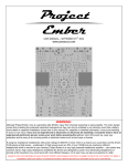
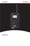
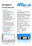
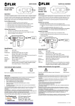
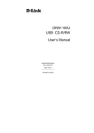
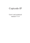
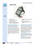
INSTALLATION GUIDE Transmitter for gas meters with pulse interface TX PULSE HP ATEX 400-006 IG UK 400-006-a DECLARATION CE DE CONFORMITE EC DECLARATION OF CONFORMITY We Enless Wireless 45 ter avenue de Verdun 33520 Bruges France Declare under our sole responsibility that the product Designation: Radio transmitters Product Name(s) & References TX PULSE HP ATEX 400-006 Attestation LCIE 14 ATEX 3013 X Notifiée par le LCIE 33 avenue du Général Leclerc - 92260 Fontenay aux Roses (France) Numéro LCIE : 0081 To which this declaration relates satisfy the provision of Directive ATEX 94/9/EC of the European parliament and the council of 23 March 1994 is in conformity with the following standard(s) or other normative document(s) EN60079-0 : 2012 / EN60079-11:2012 The marking is: II 1 G Ex ia IIC T3 Ga Fulfill the directives & standards RTTE 99/5/EC of 9 March 1999 RoHS 2011/65/EU of 1 July 2011 EN300 220-1&2 V2.4.1 (2012-05) EN301 489-1 V1.9.2 (2011-09)/ EN 301 489-3 V1.4.1 (2002-08) EN 60950-1: 2006 + A11:2009 + A12:2011 + AC: 2011 EN 5081:2012 EN61000-4-2: 2009 Date: 05/05/2014 Bruno Petit (Gérant) REMINDER REGARDING INSTALLATION OF TX PULSE HP ATEX 400-006 Referring to ATEX Directive 1999/92/CE only operators trained for risk areas are allowed to install TX PULSE HP ATEX 400-006. No changes to TX PULSE HP ATEX 400-006 are allowed. Special conditions for a safe installation TX PULSE HP ATEX 400-006 shall only be connected to intrinsically safe certified equipment .This combination must be compatible as regard intrinsic safety rules Uo, lo , Po, Co, Lo specified on TX PULSE HP ATEX 400-006 label Certifications TX PULSE HP ATEX 400-006 is ATEX certified <Ex> II 1 G Ex ia IIC T3 Ga -20°C ≤ Tamb ≤ +55°C LCIE 14 ATEX 3013 X Uo: 3,9V; Io: 2,55A; Po: 765mW; Co: 63µF; Lo: 5.5µH TX PULSE HP ATEX 400-006 complies with standards : EN60079-0 et EN6079-11 Battery Le TX PULSE HP ATEX 400-006 with LS33600 (D type) battery Only LS33600 (D type) battery can be used with TX PULSE HP ATEX 400-006. Contact details for supplying LS33600 batteries: Enless Wireless – 45 ter avenue de Verdun 33520 Bruges (France). Telephone : +33 (0) 5 56 37 97 47 – Email : [email protected] WARNING – DANGER POTENTIAL ELECTROSTATIC CHARGES TX PULSE HP ATEX 400-006 must only be cleaned with damp rag DESCRIPTION TX PULSE HP ATEX 400-006 ❸ ❼ ❽ ❷ ❹ ❶ ❻ ❺ ❶ Identification label ❷ Screws for opening/closing the lid ❾ ❶ Identification label Transmitter designation and reference > TX PULSE HP ATEX 400-006 ❸ Antenna ❹ Clamp collar brackets ❺ Wall mounting brackets ❻ Gland for wires to be connected to the meter ❼ LED indicators (L1, L2, L3) Radio frequency > 169 MHz Transmission periodicity > 60 min (default periodicity) Configurable between 1 and 250 minutes Retry > 0 (no retry – default value) ❽ LS33600 3.6 V D type battery ❾ Pulse terminal block (up to 2 pulse inputs) Device ID > 8 digit displayed under barcode CONFIGURATION OF THE TX PULSE ATEX 400006 FCT (Field Configuration Tool) software allows installation of the transmitters and configuration of RX MODBUS Receiver. Please refer to FCT user manual available on www.enless.fr 1) Position your laptop PC to the place where you intend to install the RX USB or RX MODBUS receiver. FCT software is running on your PC. 2) Connect the RX USB or RX MODBUS receiver to the USB port of your PC. If you are using RX MODBUS Receiver for the installation of the transmitters, switches DIP 1 & DIP 2 must be configured the following way DIP1: switches 5 & 6: ON - all other switches OFF DIP2: switches 1, 2 & 3 OFF Please refer to FCT manual for the complete installation of RX MODBUS Receiver 3) Fit the antenna on RX USB or RX MODBUS SMA connector 4) Start FCT software on your PC. Select English and type your user name 5) Click on “Refresh list “. The USB COM Port you have connected the receiver to will be selected. 6) Click on “Connect”. The receiver is now connected to the PC ready to receive data from TX PULSE HP ATEX 400-006 Message in the dialog box: Serial Port Connected: COMx@xxxxx 7) Select the family of the transmitters you want to install For this product you have to select « Tx Pulse » tab, then click on Edit / View. A new window will open. 8) Click on this button to add the TX PULSE ATEX 400-006 transmitter Fill in the ID in the Address field. Important: this ID is composed of 8 numbers. Define periodicity, retry, pulse count 1 and pulse count 2 Then, click on OK to add these transmitters to your configuration file. 9) Click on “Start Configuration”. You can now install the TX PULSE ATEX 400-006 transmitter. INSTALLATION OF TX PULSE ATEX 400006 CONNECT TX PULSE ATEX 400-006 TO THE METER TX PULSE ATEX 400-006 is provided with 4 wires allowing connection up to two meters Meter 1 - input 1 Input 1: wires are labeled A+ and A-. A+ is connected on terminal block to PULSE 1 - INP A - is connected on terminal block to GND Meter 2 - input 2 Input 2: wires are labeled B+ et B -. B+ is connected on terminal block to PULSE 2 - INP B - is connected on terminal block to GND Length of the wires: 150 cm. You should avoid extending the length of these wires because of potential interferences which could generate wrong pulses INSTALL TX PULSE ATEX 400-006 Set TX PULSE ATEX 400-006 at least 1.5 meter above the ground. Fix TX PULSE ATEX 400-006 Wall mounting with 2 brackets ❺ or Collar mounting with 2 brackets ❹ or DIN Rail (1 adaptor to be fitted at the back of TX PULSE ATEX 400-006 enclosure) TX PULSE ATEX 400-006 must always be installed with antenna ❸ upwards OPEN TX PULSE ATEX 400-006 ENCLOSURE Open the lid using the 4 screws ❷ START RADIO COMMUNICATION BETWEEN TX PULSE ATEX 400-006 AND RECEIVER Connect the battery to the battery connector. LED indicators L1, L2 & L3 will blink simultaneously. L1 will blink every 3 seconds. TX PULSE ATEX 400-006 is now entering configuration/installation mode. TX PULSE ATEX 400-006 will try to connect to the RX USB or RX MODBUS Receiver during 1 minute maximum If LEDs don’t blink when connecting the battery and pulling out the paper, disconnect the battery and try again. If TX PULSE ATEX 400-006 is within the range of RX USB or RX MODBUS Receiver successful installation/configuration messages as well as RSSI (Radio signal strength) will be displayed in the “message window” of FCT software The combination of L1, L2 and L3 LED indicators will confirm success or failure of the installation. See below. L1, L2 and L3 LED INDICATORS COMBINATION SUCCES OF INSTALLATION L2 & L3 LED indicators will remain ON for 30 seconds confirming the success of the installation. Transmitter is connected to RX USB or RX MODBUS Receiver. Transmitter will then switch to communication mode. It will send its data at defined periodicity (5 minutes default periodicity). L1 LED indicator will blink every minute L2 LED indicator will blink every time data will be sent from the transmitter to the receiver. SUCCESS OF THE INSTALLATION BUT LOW RSSI SIGNAL L1, L2 & L3 LED indicators will remain ON for 30 seconds confirming the success of the installation. Transmitter is connected to the RX USB or RX MODBUS receiver. However L1 LED ON confirm that the RSSI signal is low (-85 dBm or less) Message FCT: Installation is successful for (Transmitter address). Transmitter will then switch to communication mode. It will send its data at defined periodicity (5 minutes default periodicity) L1 LED indicator will blink every minute L2 LED indicator will blink every time data will be sent from the transmitter to RX USB or RX MODBUS receiver FAILURE OF THE INSTALLATION After 1 minute the transmitter failed to connect to RX USB or RX MODBUS receiver. L2 & L3 LED indicators will blink for 30 seconds meaning the transmitter is not within the range of RX USB or RX MODBUS receiver. There is no message displayed on FCT software Transmitter will then switch to communication mode. It will try to send its data at defined periodicity. L1 LED indicator will blink every minute L2 LED indicator will blink every time data will be sent from the transmitter to RX USB or RX MODBUS receiver. In case of installation failure ❶ Move the RX USB or RX MODBUS receiver antenna in order to optimize radio propagation. ❷ Move the transmitter if you can and try the procedure again If the problem remains you will have to install a repeater between transmitter and RX USB or RX MODBUS receiver. CLOSE TX PULSE ATEX 400-006 TRANSMITTER ENCLOSURE Close the lid using the 4 screws ❷ CHECK DATA RECEPTION FROM TX PULSE ATEX 400-006 WITH FCT SOFTWARE With FCT software you will be able to check that data from TX PULSE ATEX 400-006 are received correctly by RX USB or RX MODBUS Receiver. Click on «Stop configuration». Then click on «View network». You will see data from the TX PULSE ATEX 400-006 displayed on FCT software. DEVICE TYPE: TX PULSE TIME: Date & Time of data transmitted by TX PULSE ATEX 400-006 DEVICE ID: Unique 8 digit address from TX PULSE ATEX 400-006 DATA 1 ID: Pulse count 1 DATA 1: Data received by the receiver DATA 2 ID: Pulse count 2 DATA 2: Data received by the receiver RSSI SIGNAL: Radio signal strength (dBm) between TX PULSE ATEX 400-006 transmitter and RX USB or RX MODBUS Receiver > from -10 to -50 dBm : excellent radio quality signal > from - 50 to -85 dBm : good radio quality signal > from -85 dBm and lower : low radio quality signal BATTERY: Level of battery