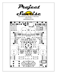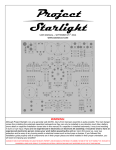
1
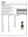
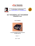
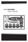
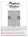
Project
Ember
USER MANUAL – SEPTEMBER 25TH 2014
WWW.GARAGE1217.COM
WARNING:
Although Project Ember runs at a generally safe 48VDC, Injury from improper assembly is quite possible. The main danger
comes from installing the polarized capacitors backwards as they can only be installed in one direction much like a battery
(more detail on capacitor installation comes later in this manual) If a capacitor is installed backwards, it may burst resulting
in burns or eye injury. If you are not experienced in electronics or electronic kit assembly, it would be wise to have an
experienced electronics person review your work before powering the unit on. Upon first power up, wear eye
protection and be wary of any burning smells or electrical noises such as loud pops or buzzes
If using low impedance headphones with power ratings of 300mW or lower, there is a chance you could blow out the drivers
if left playing at high levels – unattended. At high power levels an SPL of over 120dB may be reached in efficient
headphones which is harmful to your hearing. Project Ember is a very high powered headphone amplifier – use caution and
common sense. High output headphone amplifiers like Ember are designed to power very demanding headphones or
provide all the headroom you could want with more efficient designs, not to see if you can get your jawbone to rattle.
GARAGE1217.COM IS NOT RESPONSIBLE OR LIABLE FOR INJURY, PROPERTY LOSS OR DAMAGE AS THE RESULT OF ASSEMBLY OR USE OF THIS “DO IT YOURSELF” KIT. EMBER IS
CONSIDERED A HOBBY LEVEL PRODUCT. IT CONTAINS NO ELECTRICAL CERTIFICATIONS AND IS NOT ADVERTISED AS SUCH. USE AT YOUR OWN RISK.
Project
Ember
Specifications
- Solid state output stage
- Non overall feedback - triode voltage gain stage
- Power consumption: 5W continuous, 15W peak
- Power supply: 48VDC (0.10A cont, 0.32A peak)
- Input Resistance: 20kΩ or 40kΩ depending on gain setting
- Input Sensitivity (6N23): 0.8V or 1.6V (dependent on gain setting and used tube)
- Gain: 14- 20dB (selectable and dependent on tube)
- Max Output voltage: 15.7Vrms at 300Ω
OUTPUT
POWER
- Output Resistance: Selectable 0.1Ω, 35Ω or 120Ω
INTO:
- Frequency Response: 3Hz – 65 KHz (-0.5dB) with 32Ω load
16Ω
- Frequency Response: 1.5Hz – 190 KHz (-3dB) with 32Ω load
32Ω
- Signal to Noise ratio: 92dBA (dependent on tube)
64Ω
- Crosstalk: -89dB (dependent on tube)
120Ω
- THD: > 0.010% (dependent on tube)
300Ω
600Ω
- Suitable for: 16-600Ω Headphones, 32-600Ω recommended
OUTPUT RESISTANCE
.1R
35R
120R
600mW
1.4W
2.4W
1.8W
765mW
390mW
590mW
1.2W
1.5W
1.1W
600mW
360mW
180mW
290mW
450mW
480mW
390mW
270mW
Tubes / Valves that can be used in Project Ember
6V TUBES:
6922
7308
8223
6AQ8
6DJ8
6N1P
6H23
6H23N
6L12
6N11
6N23
B719
Cca
CV2492
CV2493
CV5358
E88CC
E89CC,
E188CC
E189CC
E288CC
ECC85
ECC88
ECC89
ECC188
ECC189
ECC288
ECC289
JAN 7308
12V TUBES:
5751
5814
5814A
5963
6189
6201
6681
7025
7058
7729
6L13
12AD7
12AT7
12AV7
12AU7
12AX7
12DF7
12DM7
12DT7
A2900
B152
B309
B329
B339
B749
CV0455
CV0491
CV0492
CV4024
12V TUBES CONTINUED:
E181CC
E183CC
E283CC
E811CC
E812CC
E813CC
E2157
E2163
E2164
ECC81
ECC82
ECC83
ECC181
ECC182
ECC182
ECC801
ECC803
ECC803S
E81CC
E82CC
E83CC
Project
Ember
Thank you for purchasing the Project Ember Headphone Amplifier Kit. This kit requires minimal electronics and
soldering knowledge. The layout is easy to follow and setup is a snap! Please make sure to follow the instructions
outlined in this guide and you will be enjoying your amp in no time. First, lets go over the tools and items required
for your build which are as follows:
Required Assembly Tools:
- Soldering iron, 25W minimum – Variable temp soldering station preferred with 1.5 – 2mm wide chisel tip
- .032 diameter 60/40 or 63/37 Tin/Lead solder is recommended. Lead free is difficult to work with and not recommended
- We specifically recommend Kester 331 water soluble flux solder, available on our website for purchase under (Parts – Buy)
- Magnifying glass (recommended but not required)
- Rubber Gloves (recommended but not required)
- 3M Green or Red Scotch Brite (recommended but not required)
- 3/32th Allen Key
- Flush cuts
- 90% Isopropyl alcohol (recommended but not required)
- Paper Towels (recommended but not required)
- Digital Multi Meter (DMM or DVOM)
- Heatgun or Hairdryer (for securing heatsinks)
Before You Start Soldering:
Prep work needs to be done. Wash your hands thoroughly and dry. Put on the recommended rubber gloves and scrub down
the PCB (circuit board) on both the front and back side with 90% isopropyl alcohol to clean any residuals off of the board
from manufacturing. Once the board has been cleaned, set it on a dry paper towel out of the way. Try to use the rubber
gloves during the entire assembly process to keep oils off of the board and solder joints.
Proper soldering is key to a quality final product. If you are new to soldering, here are some basic guidelines to
follow. It would be wise to buy a copper project board and a few cheap resistors or other components to practice
with before starting this project.
Soldering and Solder Joints:
- For best results and maximum conductivity of any component, Wipe each wire lead down using Scotch Bright. Only one
or two passes are required, making sure all of the surface has been cleaned. This removes oxidation or any other build up
on the metal that has accumulated over time. Once cleaned, it is a good idea the further clean the wire leads with 90%+
isopropyl alcohol. Make sure all alcohol has evaporated prior to soldering as alcohol is VERY FLAMMABLE.
- Do not use to much or to little solder on each joint. See images below to get an idea of what you should be looking for
- The idea is to heat the pad and the component wire lead quickly and efficiently so that solder flows to each equally.
Wetting the tip of your iron with a very small amount of solder will aid in quickly heating up the pad and wire lead.
- Having to heat a component for long periods of time, especially capacitors or LED’s is NOT a good thing. When soldering
capacitors or LED’s, heat them only long enough to ensure a quality joint and let the unit cool down before soldering the
second lead.
- The solder joint should look bright and metallic. A dull or dark gray looking joint is referred to as a
“cold solder joint” Cold solder joints may not pose a problem initially, but can show up later in the amps life.
- After every solder joint, make sure to clean the flux off your soldering iron tip with a wet sponge that should be
provided with your soldering iron kit.
CUTAWAY OF A VIA AND SOLDER PAD
PRIOR TO SOLDERING:
VIA / HOLE
PCB
CUTAWAY
SOLDER
PAD
WIRE
LEAD
PROPER SOLDER JOINT:
IMPROPER SOLDER JOINT:
- Solder is bright and shiny. It is curved
smoothly starting at the edge of the solder
pad until it reaches the lead from the
component
- Solder should fill the via and flow through
the board slightly. It is ok to add solder to
the top side of the board, however it is not
required
- A large blob of solder, often dull in color is
not desired. The solder may not flow into
the via hole and cause a poor connection
or failure later in the amplifiers life.
TOP OF PCB
TOP OF PCB
Project
Ember
Bottom Chassis Prep / Final Chassis Assembly:
- ONCE THE PCB HAS BEEN ASSEMBLED,
ASSEMBLE EACH OF THE 4 RUBBER FEET AS
SHOWN, ATTACHING EACH FOOT TO THE GRAY SET IT ONTO THE FOUR THREADS
STICKING OUT OF THE BOTTOM GRAY
SMOKED ACRYLIC BOTTOM CHASSIS
ACRYLIC CHASSIS THAT YOU
PREVIOUSLY ASSEMBLED.
THREADED SPACER
GRAY ACRYLIC BOTTOM
RUBBER FOOT
NYLON WASHER
4-40 BUTTON CAP SCREW
- THREAD ON EACH OF THE FOUR HEX
STANDOFFS ONTO THE THREADS THAT
ARE NOW PROTRUDING THROUGH THE
PCB, SECURING THE PCB TO THE GRAY
ACRYLIC CHASSIS BOTTOM. PROCEED
TO POWER ON THE UNIT (AS DESCRIBED
ON PAGE 2, WEARING EYE PROTECTION
AND AT A SAFE DISTANCE IN CASE OF A
MISTAKE IN ASSEMBLY)
- ONCE THE AMPLIFIERS FUNCTIONALITY
HAS BEEN TESTED AND THE UNIT HAS
HAD A CHANCE TO FULLY WARM UP FOR
30 MINUTES, SET THE BIAS AS
DESCRIBED LATER IN THIS MANUAL
BEFORE PLACING THE TOP CLEAR
ACRYLIC COVER IN PLACE
THUMB SCREW
CLEAR ACRYLIC TOP
STANDOFF
PCB
THREADED SPACER
GRAY ACRYLIC BOTTOM
Project
Ember
Project Ember Operation Guide:
Normal Operation and Notes:
- Plug in the amplifier and then the power supply (in that order). Make sure the tube, headphone jack and input RCA’s are
secure. Once the amplifier is turned to the ON position, the front red LED (closest to the volume knob and headphone jack)
will illuminate red for approximately 30 seconds. This indicates the protection circuit is active while the tube is warming up.
It may take several minutes for the tube to fully warm up depending on the tube type used
- When the protection circuit activates and de-activates, a slight click may occur
- When the power switch is turned on and the amplifier is plugged in, the red LED at the back of the amplifier will illuminate
- Depending on the tube type chosen and the sensitivity of headphones used, background noise (hiss) may be present.
Choosing a higher output impedance setting, or a lower gain tube can generally eliminate any background noise with
sensitive headphones. This does not mean a high gain tube can not be used in our designs. Selecting a higher output
resistance or lower input gain setting may reduce noise with higher gain tubes. We advise you experiment with several
tubes to find out what you like best
- If load testing Project Ember, it is not recommended to attach a dummy load with a value below 15Ω when testing at full
output power for a long periods. Heatsinks and the output devices at the bottom will become quite hot during testing. The
amplifier will go into thermal protection when chip temperatures of 150oC are reached, indicated by the red protection LED
at the front of the amplifier. Under normal conditions (playing music) even when driving low impedance loads, the output
devices will get slightly warm at best.
- Some channel imbalance below 9 o’clock on the volume potentiometer is normal. We recommend you adjust your source
output levels and use Project Ember with a volume setting of 9 o’clock or greater
- If input capacitors are bypassed, you will hear a scratching sound when adjusting the volume potentiometer
- Some faint scratch when turning the volpot is normal. This does not indicate a bad volpot – just a micro amount of DC that
is present with certain tubes. This type of scratch is generally only heard with no music playing / rotating the volpot
- Cell phones or radio frequency devices in close proximity to Project Ember may create noise that is audible when listening
to music (generally clicks or digital noises)
- Clean your Project Ember with a microfiber cloth and plastic cleaner (dusting with a microfiber cloth is generally all that is
required). Compressed air is also great option for dust.
- Dual triode tubes with high heater current demands (above 500mA) are not recommended for this design (UNLESS
EQUIPPED WITH A SUPERCHARGER MODULE). They may work without issues but the risk of the DC regulator IC2
failing after a certain period is possible.
.
- When the RGB LED (LED under the tube) flickers upon startup, the (temporarily, current demand is higher than the
regulator can handle. An example of tubes with very high startup current demands would be an E80CC or 12BH7's. If this
flickering stops within a few seconds and the tube lights up normally, then you should be O.K. If this flickering takes longer
than 10 seconds, this particular tube should not be used
.
- Hot swapping tubes is not recommended (swapping tubes while the amplifier is on). Even though it does not cause
technical errors or malfunctions it could damage headphones rated for 1W or less.
Project
Ember
Assembly Guide
RCA LINE-OUT
POWER
JACK
POWER
SWITCH
RCA LINE-IN
POWER LED
ADJUSTABLE INPUT GAIN
JUMPERS
LED ON/OFF
LED COLOR CHANGING
TRIMMERS
INPUT CAPACITOR BYPASS
OUTPUT RESISTANCE
JUMPERS
PROTECTION CIRCUIT LED
¼” - 6.3MM
HEADPHONE JACK
WHEN THE AMPLIFIER IS TURNED ON,
THIS LED WILL LIGHT FOR
APPROXIMATLEY 30 SECONDS
INDICATING THE PROTECTION CIRCUIT IS
ACTIVE WHILE THE TUBE WARMS UP
IF THERMAL LIMIT IS EVER REACHED,
THE PROTECTION CIRCUIT WILL
ACTIVATE AND THE LED WILL LIGHT
VOLUME
POTENTIOMETER
Project
Ember
STEP 1: POPULATE ALL SMALL COMPONENTS ON THE BOARD SUCH AS RESISTORS, RIGHT ANGLE JUMPERS,
DIODES AND SMALL CAPACITORS. THROUGHOUT YOUR BUILD, ALWAYS INSTALL THE SMALLER PARTS FIRST,
WORKING YOUR WAY UP TO THE LARGER COMPONENTS
FLAT SPOT OR THE
SHORT LEAD ON RED LED
(INDICATES NEGATIVE
SIDE OF LED) MUST FACE
EXACTLY AS SHOWN
PAY CLOSE ATTENTION
TO THE GRAY BAND ON
EACH DIODE AS THEY ARE
DIRECTIONAL
NOTCH ON THE RGB LED
(ORIENTATION MARKING)
MUST FACE THE WHITE
MARKING ON THE PCB AS
SHOWN
LED MUST BE INSTALLED
BEFORE SOLDERING THE
TUBE SOCKET IN PLACE
PAY CLOSE ATTENTION TO
THE BLACK BAND ON ALL
DIODES OR ZENERS AS THEY
ARE DIRECTIONAL
- RESISTORS AND INDUCTORS ARE NONPOLAR AND CAN BE FITTED IN EITHER DIRECTION. WHEN INSTALLING COMPONENTS,
MAKE SURE THE COMPONENT VALUES ALWAYS FACE UP SO THEY ARE VISIBLE (CAN AID IN TROUBLESHOOTING IF A
COMPONENT IS PLACED IMPROPERLY)
- DIODES, TRANSISTORS, IC’S AND ELECTROLYTIC CAPACITORS ARE POLAR AND PROPER ORIENTATION IS REQUIRED
Project
Ember
STEP 2: POPULATE ALL MID SIZE COMPONENTS SUCH AS RCA’S,
POWER COMPONENTS, SMALL CAPACITORS, TUBE SOCKET,
RELAYS, TRIMMERS AND SO FORTH
PLEASE NOTE: CENTER
PIN OF DC SOCKET IS
POSITIVE / 48VDC+
OPAMP IS DIRECTIONAL
MAKE SURE THE BLACK
DOT (PIN 1) IS CLOSEST
TO THE TUBE SOCKET
WHEN INSTALLED
INPUT CAPACITORS ARE
NONPOLAR MEANING
THEY HAVE NO STRIPE
AND CAN BE INSTALLED
IN EITHER DIRECTION
POLARIZED CAPACITORS MUST BE INSTALLED IN THE
CORRECT DIRECTION (WILL HAVE A STRIPE DOWN THE SIDE
DESIGNATING POLARITY) INSTALL THIS STRIPE FACING THE
FLAT SPOT ON THE CAPACITOR OUTLINE ON THE BOARD
CORRECT
INCORRECT
PEEL OFF THE PROTECTIVE
ADHESIVE LAYER ON THE
BOTTOM SIDE OF THE
HEATSINK(S). PLACE THE
HEATSINKS DIRECTLY OVER
THE THERMAL PADS ON THE
PCB. ONCE INSTALLED, USE A
HAIR DRYER OR HEATGUN TO
BREIFLY HEAT UP EACH
HEATSINK WHICH WILL
ACTIVATE THE ADHESIVE.
CAUTION: IF USING A
HEATGUN, ONLY APPLY HEAT
FOR A FEW SECONDS DIRECTLY
ONTO EACH HEATSINK
Project
Ember
VOLPOT GROUNDING
GROUNDING THE VOLUME POTENTIOMETER IS REQUIRED AS
WITHOUT IT, THE AMPLIFIER MAY BE SUBJECTED TO NOISE /
INTERFERENCE.
THE IMAGES ARE OF THE PREVIOUS GENERATION SUNRISE,
HOWEVER THE GROUNDING PRINCIPAL IS EXACTLY THE SAME.
FIRST, INSERT A WIRE LEAD INTO THE RIGHT SIDE VIA NEXT TO THE
VOLPOT AND SOLDER IN PLACE.
WRAP THE WIRE LEAD AROUND THE THREADED PORTION OF THE
VOLPOT AS SHOWN.
PUT ON WASHER AND NUT INCLUDED IN THE KIT. ONCE TIGHT, THE
VOLUME KNOB MAY BE INSTALLED.
Project
Ember
STEP 3: POPULATE ALL LARGE SIZE COMPONENTS SUCH AS LARGE CAPACITORS, TO220 DIODE AND
HEADPHONE JACK
POSITION THE TO220 DIODE
EXACTLY AS SHOWN
Project
Ember
COMPLETED EMBER LAYOUT AND PHOTO:
Project
Ember
Project Ember has several jumpers settings to customize the amp the way you would like it. Below gives you the
details on what these jumper settings do!
INPUT GAIN CAN BE CHANGED VIA THE LG (LOW GAIN) AND HG
(HIGH GAIN) JUMPER TABS AT THE BACK, RIGHT HAND CORNER OF
THE AMPLIFIER. DEFAULT SETTING IS LOW GAIN. HIGH GAIN WILL
INCREASE LEVELS BY APPROXIMATLEY +6dB
INPUT CAPACITORS CAN BE BYPASSED PER YOUR PREFERENCE.
MANY VIEW THIS AS A PURIST FUNCTION AS IT IS ONE LESS
COMPONENT IN THE SIGNAL PATH. WITH INPUT CAPS BYPASSED,
YOU MAY HEAR A SCRATCHY SOUND WHEN ADJUSTING VOLUME.
THIS WILL NOT DAMAGE YOUR HEADPHONES OR YOUR AMPLIFIER
TC = SIGNAL GOES THROUGH CAP (EXAMPLE SETTING IN RED)
BP-C = SIGNAL DOES NOT GO THROUGH INPUT CAP (BYPASSED)
OUTPUT RESISTANCE IS CONFIGURABLE BETWEEN 0.1Ω (LOW)
35Ω (MID) AND 120Ω (HIGH). HIGHER OUTPUT
RESISTANCE CAN HAVE AN EFFECT ON BASS AND/OR TREBLE
FREQUENCIES. THIS EFFECT IS DEPENDANT ON THE HEADPHONE
IMPEDANCE. (EXAMPLE OF 35Ω SETTING IN RED) EXPERIMENT BY
CHANGING THE SETTINGS TO FIND WHAT YOUR PREFERENCE IS
Project
Ember
LED Light Color
RGB LED
LED ON / OFF
COLOR / BRIGHTNESS
ADJUSTMENT TRIMMERS
BLUE
RED
GREEN
Another feature of Project Ember is an adjustable RGB (RED GREEN BLUE) LED under the tube. RGB LED’s can produce
almost any color desirable. We understand this is not an audiophile feature or a feature that has anything to do with the
sound of the amplifier. Each of us has a favorite color that is enjoyable to look at. Using the three trimmers located above,
you can dial in any color you desire and also the brightness of that color. Often manufacturers tie you into their specific color
scheme on their products. We feel it is important for you to choose the color you desire which can set an enjoyable mood
when listening to your music. Adjust the brightness and color by turning each of the trimmers with a small jewelers
screwdriver. Or simply disable the RGB LED (jumper) enjoy the glow of the tube.
Project
Ember
OPA551 OUTPUTS
THE OUTPUT STAGES OF THE AMPLIFIER (OPA551 - DDPAK7 IC’S) ARE LOCATED ON THE BOTTOM SIDE OF THE
AMPLIFIER. THEY COME PRE-INSTALLED – REFLOW SOLDERED TO THE PCB. PRIOR TO SHIPPING, ALL FLUX
FROM THE REFLOW PROCESS WILL BE CLEANED AND REMOVED FROM THE PCB
IT IS NORMAL FOR A SMALL AMOUNT OF SOLDER TO BLEED THROUGH THE THERMAL VIAS AND BE VISIBLE ON
THE HEATSINK THERMAL PAD (LARGE GOLD SQUARES ON THE TOP SIDE OF THE PCB). WHEN INSTALLING THE
HEATSINK(S), THE SOLDER WILL NOT BE VISIBLE
DO NOT ATTEMPT TO REMOVE OR REPLACE THE OPA551's WITH ANY OTHER TYPE
Project Ember
Resistors
R1 = SM 100K X2
R2 = SM 470K X 1
R3 = SM 10K X 1
R4 = SM 220K X 1
R5 = SM 330R X 2
R6 = SM 4K7 X 1
R7 = LG 47R X 2
R8 = LG 120R X 2
R9 = LG 10K X 2
R10 = LG 2.2K X 2
R11 = SM 220R X 3
R12 = SM 22K X 2
R13 = LG 100K X 2
R14 = LG 1K X 2
R15 = LG 0R X 2
R16 = LG 1K X 2
R17 = SM 1K X 1
R18 = SM 39K X 1
R19 = SM 10K X 1
R20 = SM 1K X 1
R21 = SM 18R X 1
R22 = SM 39K X 2
R23 = SM 39K X 2
R24 = SM 18K X 2
R25 = SM 1K8 X 2
R26 = LG 20K X 2
R27 = LG 220R X 2
R28 = LG 1K X 2
R29 = SM 100K X 1
Diodes
Z1 = BZX79-C43 X 1
Z2 = BZX79-C39 X 1
Z3 = BZX79-C10 X 2
Z4 = BZX79-C22 X 2
D1 = RED LED X 1
D2 = 1N4148 X 2
D3 = 1N4148 X 2
D4 = 1N4148 X 2
D5 = 1N4148 X 2
D6 = RGB LED X 1
D7 = SB140 X 2
D8 = TO-220 DIODE
D9 = RED LED X 1
Regulators
IC1 = OPA551 X 2
IC2 = DC-DC X1
IC3 = TS921 X 1
Jacks
J1 = HEADPHONE JACK X 1
J2 = TUBE SOCKET X 1
J3 = BLACK RCA JACK X 2
J4 = RED RCA JACK X 2
J5 = POWER INPUT JACK X 1
Capacitors
C1 = 47uF 63V X 1
C2 = 47pF X 2
C3 = 2200uF 63V X 2
C4 = 1uF X 2
C5 = 470uF 10V X 2
C6 = 10uF 63V X 2
C7 = 10uF 63V X 3
C8 = 100uF 16V X 2
C9 = 4.7uF 63V X 1
C10 = 47uF 100V x 4
C11 = 100nF X 4
C12 = 100nF X 2
Transistors
Q1 = BC546 X 3
Q2 = BC556 X 3
Inductor
L1 = 100uH X 1
Jumpers
JP1 = 4 PIN RA X 2
JP2 = 3 PIN STRAIGHT X 5
Switches
SW1 = POWER SWITCH X 1
Potentiometers / Trimmers
P1 = 10K VOLUME POTENTIOMETER X 1
P2 = 50K SINGLE TURN TRIMMER X 3
Relay
U1 = 48V RELAY X 1
U2 = 5V HIGH SENSITIVITY RELAY X 1
Other
HEATSINK X 2
JUMPER TABS X 7
G1217
Supercharger
USER MANUAL – JULY 3RD 2014
WWW.GARAGE1217.COM
Designed to increase available heater current from 500mA (600mA peak) to well past 1A. This allows a
much broader qty of tubes to be rolled into your Project Ember. Tubes such as the 6n6p, 6n30p, 12bh7
and so forth can now be used and powered properly! Also initial tube warm up time is drastically
decreased (with tubes drawing 500mA or more)
G1217
Supercharger
INSTALLING THE SUPERCHARGER INTO PROJECT EMBER:
DE-SOLDER THE ORIGINAL DC-DC
CONVERTER LOCATED HERE (IF
BUILD IS PRE-EXISTING). MAKE SURE
THE VIAS HAVE BEEN CLEANED OF
SOLDER
INSERT THE SC PINS AS SHOWN INTO IC2
G1217
Supercharger
INSTALLING THE SUPERCHARGER INTO PROJECT EMBER:
NOTICE THE SC MODULE WILL SIT
ABOUT 4MM HIGHER THAN THE
REAR 47uF 100V CAPACITORS
PRESS DOWN FIRMLY ON THE
SUPERCHARGER MODULE UNTIL THE
MODULE SITS FLAT ON TOP OF THE
REAR 47uF 100V CAPACITORS
(PLASTIC RETAINER ON 3 PIN
HEADER WILL SLIDE WHEN PRESSED)
G1217
Supercharger
INSTALLING THE SUPERCHARGER INTO PROJECT EMBER:
ONCE IN POSITIONE, SOLDER THE 3
PIN HEADER INTO PLACE AND CUT
LEADS ACCORDINGLY
PHOTO OF THE MODULE INSTALLED