1
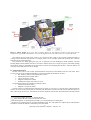
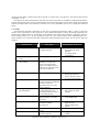
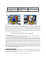
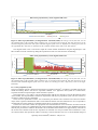
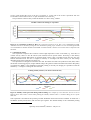
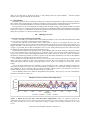
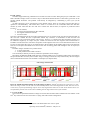
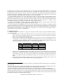
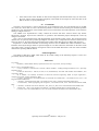
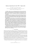
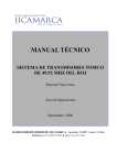
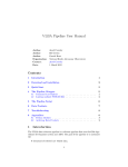
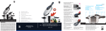
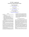
Attitude Control on TET-1
Experiences of the First Year of Operations
Markus Hobsch1, Fabiana Cossavella2, Sebastian Löw3, Jaap Herman4
Deutsches Zentrum für Luft- und Raumfahrt e. V., German Aerospace Center
Münchner Straße 20, 82234 Wessling, Germany
The micro-satellite TET-1 carries several technology experiments. It is the first in a series
offering the possibility of in-orbit verification of new equipment made in Germany by the
industrial and scientific aerospace community. TET-1 was launched 22nd July 2012 and is
operated by the German Space Operations Center.
Attitude and attitude control is influenced by several of the experiments. Special attitude
control modes are required for a number of experiments in order to point the satellite in a
prescribed direction or to a specific location on Earth. These comprise an experiment with
three infra-red cameras, a pico thruster and finally a new type S-band transponder. The Li
Polymer battery was not expected to have any effect on attitude control. However, it was
discovered that charging and discharging the battery disturbs the magnetic field sensors,
thus a different approach to attitude control is required when it is in use. Implementation of
and special demands on the attitude control system for these experiments will be presented.
The mission is experimental with high demands on the attitude control system. The
envisaged duration was one year only with a possible prolongation of a further year.
Components were therefore not chosen for longevity. However, the actual amount of
disruptions due to sensor and/or actuator outages and due to idiosyncrasies in the
spacecrafts thermal budget was higher than expected. The ensuing challenges for the
attitude control system will be discussed.
A software upload in May 2013 mitigated several of the issues addressed above. The
improvements in the software and autonomous on-board reactions will be presented in the
final Section together with some recommendations for the follow-on missions TET-2 and
BIROS.
I. Introduction
T
first Section gives a short overview of the TET-1 mission, the payload experiments which were performed in
the first year, and their impact on attitude control. The German Technology Experiment Carrier TET-1 was
successfully launched on 22nd July 2012 and marks the first mission within the OOV (on-orbit verification) program.
The eleven payloads on board were tested in a space environment over a one-year period until 31st October 2013.
The mission now continues under the name “Firebird” primarily making IR images of the Earth.
HE
A. The TET-1 mission
The primary goal of the mission is to offer a platform for the verification of eleven experiments (ten German and
one Dutch) in low Earth orbit. The payload comprises among others a new kind of solar cells, new batteries and a
new GPS receiver type. The orbit is Sun-synchronous with a height of 523 km and a resulting orbital period of 96
minutes. The bus is based upon the one used for BIRD3, which has already been verified in orbit.
1
ACS Subsystem Engineer and Flight Director, DLR-GSOC, 82234 Wessling, Germany. [email protected]
ACS Subsystem Engineer, DLR-GSOC, 82234 Wessling, Germany. [email protected]
3
ACS Subsystem Engineer, DLR-GSOC, 82234 Wessling, Germany. [email protected]
4
ACS Team lead, DLR-GSOC, 82234 Wessling, Germany. [email protected]
1
SpaceOps 2014; Pasadena, California – May 05 - 09
2
Figure 1. TET-1 design. View of the TET-1 satellite. Shown are the different segments of the spacecraft, the
arrangement of payloads and antennae, as well as the flight direction. The solar arrays are seen from the back.
The attitude control system (ACS) itself is very specific because it has to meet several requirements that are
coming from the different experiments. For example, TET-1 has no standard operational mode but uses a distinct
attitude mode for each experiment.
The preferred ACS mode during the first year of operations was Sun Pointing Fix Mode (SPFM)a. The Sun
Pointing Rotate Mode (SPRM)b had to be used due to thermal issues for a longer test period. The Earth pointing
mode (EPM)c must be commanded for ground station contacts when the high gain antenna is required. EPM is not
necessary if downlink with low-rate is enough.
B. Attitude information
Because TET-1 has no orbit control, the determination and control of the attitude came into main focus. There
are five types of sensors with high redundancy on-board for attitude determination on TET-1:
• Star Trackers (with 2 Camera Head Units (CHU))
• Inertial Measurement Units (IMU)
• Coarse Sun Sensors (CSS)
• Magnetic Field Sensors (MFS)
• Global Positioning System (GPS) receivers
The following actuators are available for attitude control:
• four Reaction Wheels (RW)
• Magnetic Coil System (MCS)d
The Star Trackers can determine the attitude most accurately. An accuracy of 1 arcmin can be achieved with one
camera, 30 arcsec if both cameras deliver valid data. The aberration correction derived from the GPS data improves
these values by up to 29 arcsec. The attitude can also be estimated from the last valid measurement and the rotation
a
xsat-axis points in flight direction, -zsat towards the Sun
-zsat points towards the Sun, rotation around the Sun vector
c
Nadir Ponting mode: zsat pointing towards Nadir, ysat-axis perpendicular to orbital plane
d
The MCS was originally foreseen for wheel desaturation only. The S/W update (see chapter III-D) made the MCS
available as actuator for attitude control during ACS Safe Mode.
2
SpaceOps 2014; Pasadena, California – May 05 - 09
b
rate derived from IMU, if both cameras deliver invalid, or no data. This is only done for <200 min because the drift
of the IMU is 1 °/h7.
The attitude can still be determined if only data from CSS and/or MFS are available for attitude determination.
The Sun and magnetic field vector are determined by the On-board Navigation system (ONS) model and compared
with the measured values. The model has a variance of 0.3° and a maximum error of 0.8°7 compared to measured
values.
C. Payload
All experiments and their requirements on the ACS are summarily described in Table 1. Figure 2 shows the
location of the experiments in the spacecraft. A more detailed description of three interesting experiments has
already been presented in Ref. 2. Nevertheless, some influence ACS routine and contingency operations. These are
the Li-Polymer battery (N1), the pico propulsion system (N7), the infrared camera (N15) and KERAMIS (N18).
These examples were chosen because their requirements and operational impacts on the ACS are diverse and most
stringent.
Payload Name
Description
N1: Li-Polymer Battery
Charge and discharge cycles to
investigate behavior
Requirements on the ACS
-
N2: Flexible thin layer solar
cells
N6: Sensor bus system and
current drain
Measure performance
-
Measurements must be in
Sun pointing fix mode
(SPFM)
No magnetorquer
commanding
Sun pointing
Verification of application
capability of a sensor bus
system. The current drain
works as a variable electrical
load for the experimental solar
cells (N2, N8 and N9).
-
None
N7: Pico propulsion system
New kind of propellant system
-
N8: Next generation solar cells
Improve calibrations against
specific atmospheric conditions
and derive solar cell
degradation due to UV and
particle radiation
Test performance, solar cells
are integrated in the solar
generator and deliver power to
the bus when running
Set of three cameras to detect
high temperature events like
forest fires
Precise orbit determination and
Earth limb sounding
measurements
-
No active attitude control
during experiments in
order to measure effects
on ACS (Suspend mode)
Sun pointing
-
N9: Next generation solar cells
(by ASTRIUM)
N15: IR camera
N16: Secondary frequency GPS
N17: HW BOSS
N18: KERAMIS
-
Measurements must be in
Sun pointing fix mode
(SPFM)
-
Earth or target pointing
mode (EPM/TPM)
-
Forward or backward
flight direction
Earth pointing mode
(EPM)
none
-
New kind of H/W Operating
system
Three experiments to test new
- Target pointing mode
satellite to ground
(TPM)
3
SpaceOps 2014; Pasadena, California – May 05 - 09
N19: Memory orbit radiation
Experiment
communication modules
(receiver, transmitter)
Investigate impact of radiation
on memory units
-
none
Table 1. List of experiments. A short description of the purpose of each experiment is given in column two, the
requirements for ACS in column three.
Figure 2. Payload arrangement. View of the payload segment and the location of different experiments. The image
on the left-hand side still shows one experiment which was eliminated during the mission preparation (N4 – Multi
frequency GPS). The three black cylinders on the back side of the satellite are the baffles of the IR camera (N15).
The sensor bus (N6) and the GPS experiment (N16) are mounted on top of the spacecraft. On the side the GPS
antenna (N16) and the Li-Polymer battery (N1) are visible. The KERAMIS payload (N18) is mounted above the IR
camera. On the right-hand side the radiator of the battery (N1) on top of the GPS payload, the KERAMIS antenna,
and the Microjet propulsion system (N7) can be seen. Not visible in this picture are the three solar cell experiments
(N2, N8, N9), which are located on the front side, the HW BOSS (N17) and the mass memory (N19). A short
description of the experiments is given in Table 1.
II. Observations of interactions between ACS and experiments
A. N1 Li-Polymer battery
The battery was charged or discharged and parameters such as charge current, voltage and temperature were
recorded. Charging is of course only possible during phases with sunlight.
The measurements of the magnetometer (especially those of MFS2) are disturbed by this experiment. This is
because a dipole moment is generated within the payload during charging or discharging. Battery operations have a
high load on the spacecrafts power system. Therefore, the Sun-pointing mode SPFM is prescribed. In this mode the
star cameras provide the attitude measurements, so the disturbances on the MFS have no impact on the attitude
determination. During LEOP it was tested whether effects measured on ground can be measured in space. The effect
of the magnetic dipole generated by the payload battery on MFS1 can be seen in Figure 3, the effect on MFS2 in
Figure 4.
The analysis shows that MFS1 is not noticeably affected. A small jump is seen when charging starts and stops. A
different behavior is observed for MFS2, which is mounted closer to the payload battery. The induced moment
disturbs the measurements of the magnetic field of the Earth during the entire period of battery operations. An
autonomous switch from the measured data to the model of the magnetic field is made after about five minutese. The
magnetic field vector, determined by the MFS, is fudged during battery charge or discharge processes. Nevertheless
the ACS is still compliant with the requirements8.
e
The ACS usually uses the model based magnetic field vector instead of the vector derived from the measured data
for attitude control. The latter is only used for safety checks. If the vectors differ more than 5°, the algorithm will
allocate the error to the model and will deactivate the use of the model. The magnetic field vector derived from the
data of the magnetometers will be used.
4
SpaceOps 2014; Pasadena, California – May 05 - 09
Effect of the payload battery on the magnetic field sensor
1,00
0,80
4
0,60
2
0,40
0
-2
11:30
dB/dt [°/s]
Current [A]
6
0,20
0,00
11:40
11:50
Time [hh:ss]
PAYLOAD CURRENT
d(B_meas)/dt
12:00
d(B_est)/dt
∆B
Figure 3. Effect of payload battery on magnetometer 1 (DoY207, 2012). The charge current (blue line, axis on
the left-hand side) of the payload battery indicates the N1 switch-on and switch-off. The time derivatives of the
measured magnetic field vector and of the estimated magnetic field vector are displayed in red and green (axis on
the right-hand side). The latter is calculated by the estimator module and is used by the ACS software.
The magnetic field vector is also used as input for reaction wheels desaturation using the magnetorquers. The
MCS is taken out of the control loop during this experiment in order to avoid erroneous commanding.
Effect of the payload battery on the magnetic field sensor
1,00
0,80
4
0,60
2
0,40
0
-2
13:10
dB/dt [°/s]
Current[A]
6
0,20
13:20
PAYLOAD CURRENT
13:30 Time [hh:mm]
d(B_meas)/dt
0,00
13:50
13:40
d(B_est)/dt
Figure 4. Effect of payload battery on magnetometer 2 (DoY208, 2012). The charge current (blue line, axis on
the left-hand side) of the payload battery indicates the N1 switch-on and switch-off. The time derivatives of the
measured and estimated magnetic field vectors are shown as red and green lines, respectively (scale on the righthand side).
B. N7 Pico propulsion system
The pico propulsion system is based upon the Resisto-jet actuation principle4. It contains a propellant system from
which the working fluid is led into an evaporation chamber via a propulsion feed system. It is heated there,
evaporates and then escapes through a nozzle when this is opened.
The torque from a 1 sec. pulse is ≤50 Nm. Measurements with the star cameras are used to determine the effect
on the attitude. The Suspend Mode is needed for experiments with the pico propulsion system. All ACS sensors are
used but no actuators will be commanded.
There were two operational scenarios: one in which the pico thrusters were switched on for about two minutes
only in order to perform a health check and a second where the thruster were also allowed to fire. It is not possible to
command the start of the pulsing by command, because this is governed by temperature.
Scenario two was tested 13 times. Pico propulsion was activated either for 14 or 22 minutes. In order to meet the
requirements no torques are commanded to the reaction wheels and wheel desaturation is also disabled ascertaining
that only the pico thrusters influence the attitude. The accumulated thrust duration was approximately 4 minutes in
the 14 min. and 12 minutes in the 22 min. experiment. A maximum of 0.725 rpm rotation rate around the S/C z-axis
was observed in the first experiment, which is caused by a mean acceleration of 0.018 °/s² and an attitude change of
5
SpaceOps 2014; Pasadena, California – May 05 - 09
123.56° (again around the z-axis of the S/C) (see Figure 5). At the end of the 22 min. experiment TET was
accelerated to a mean rotation rate of 1.6 rpm around the z-axis of the S/C.
The pico thruster can thus easily control the attitude of a 100 to 150 kg9 satellite.
rotation rate [rpm]
Satellite rotation rates during N7 experiment
0,6
0,4
0,2
0
-0,2
-0,4
-0,6
-0,8
07:25
07:30
07:35
Roll
Time [hh:ss] 07:40
Pitch
Yaw
07:45
07:50
Figure 5. N7 experiment on DoY172, 2013. The experiment started at 07:29. TET-1 was commanded into SPM.
Around 07:40 N7 was heated up enough to start autonomous pulsing. After 4 minutes N7 was switched off and TET
was commanded to nominal attitude mode SPFM. It needed around 5 minutes to slew back and to compensate this
deviation.
C. N15 Infrared camera
This experiment comprises three cameras to detect high temperature events on the Earth, e.g. forest fires or
volcanic activity. There are two IR cameras (near infrared) and one optical camera. Processing is done directly
within the NVS (German abbreviation for payload supply system). This is possible because the NVS also gets
attitude information from the ACS. It might be necessary to reconfigure the mass memory for data storage
depending on the scenery that has to be observed.
The experiment was designed to match the TET orbit. Deviations from this Sun-synchronous orbit (SSO) reduce
the amount of interesting objects; a higher altitude changes the ground resolution and therewith reduces data quality
in comparison to BIRDf. 3-axis stabilization with nadir pointing is necessary for imaging. It is possible to rotate the
satellite by +/- 30 degree to enlarge the area observed.
Pointing stability of EPM (+18° offset around roll-axis)
d/dt [arcmin/sec]
2
1
0
-1
-2
13:34:30
13:34:31
13:34:32
13:34:33
13:34:34
Roll
13:34:35 13:34:36
Time [hh:ss]
Pitch
Yaw
13:34:37
13:34:38
13:34:39
13:34:40
Figure 6. Stability of the spacecraft during Nadir Pointing. One example of a N15 data take: the rate errors in
EPM is shown. Once TET-1 reaches nadir pointing the stability remains below 1.7 arcmin/s during the 10 s of the
data take.
This experiment is essential for the upcoming scientific DLR Earth observation mission “FireBird” in which TET-1
and BIROS (launch planned 2015) will form the space segment. The attitude stability of the commanded pointing
f
Satellite launched in 20013
6
SpaceOps 2014; Pasadena, California – May 05 - 09
during an N15 data take is displayed in Figure 6. The pointing meets the required stability10. Thus the Firebird
mission can be supported without any restrictions.
D. N18 KERAMIS
KERAMIS comprises three experiments probing new techniques and modules for data transmission in the Kaband. Among others, high-frequency modules for transmission and reception in the Ka-band have been qualified for
use in space. An S-band transponder was used for a bi-directional transmission of measurement data.
The experiment serves as a transponder providing up and down-link. Target pointing Mode (TPM) was needed
for the transmission. A constant signal from the ground station in Weilheim (WHM) was transmitted to the satellite.
Some TET-1 contacts over WHM were used for this experiment and normal up-and down-link had to be suspended
during this experiment. No real time monitoring was possible.
III. Challenges for ACS
A. Data from reaction wheels flagged unhealthy
On TET-1 four RW 90-2 “smart” wheels of the German manufacturer Astro- Feinwerktechnik Adlershof GmbH
are used. They are mounted in a triangular pyramid configuration.
Several issues with the reaction wheels were a major point of concern to ACS during the first year. The
communication between the ACS software thread and the RWs was interrupted several times because wheels were
flagged “unhealthy”. The first response was a power cycle by switching the relay of the corresponding wheel off and
on again. No particular wheel could be identified as the root cause of the problem because each of the four wheels
was delivering invalid data for roughly the same amount of time.
Detailed analysis identified two possible causes for the unhealthy data. The smart wheels are designed such that
a reset occurs autonomously if an inconsistency is recognized. In this case an internal counter increments by one
step for each occurence. Data will be flagged unhealthy if the counter exceeds 20. It was not possible to reproduce
this behavior and the large amount of reboots on ground, so the most likely explanation is an effect of the radiation
in space, although no correlation with space weather was found.
It is possible to restart the wheels not only by a power cycle (relay switching) but also by performing a soft
reboot. The latter would have solved the contingency described above and would have been better for the
operational lifetime than the actually commanded power cycles. It also was decided to reset the error counter
weekly.
The second cause could be a freeze of the RW’s core processing unit (CPU). Again this behavior had not been
observed in pre-launch tests and it was tried unsuccessfully to reproduce it. It is most likely caused by radiation as
well, although no direct correlation with tests and space weather could be found. A soft reset does not solve the
problem and only a power-cycle brings back the wheel into control loop.
The two different failure cases cannot be distinguished in the telemetry. Thus a power cycle was commanded in
all fourteen cases that occurred so far.
RW speed in the four- and three-wheel configurations
Wheel speed [rpm]
2000
1000
0
-1000
-2000
16:00
17:00
18:00
19:00
RW1
20:00
Time [hh:ss]
RW2
RW3
21:00
22:00
23:00
00:00
RW4
Figure 7. Wheel speed in the four- and three-wheel configurations. RW3 was isolated around 20:00,
commanded torque dropped to zero and its speed remained constant (green line). Attitude control was taken over by
RW1, RW2 and RW4 in a three-wheel configuration leading to higher load and higher amplitude in the wheel
speeds.
7
SpaceOps 2014; Pasadena, California – May 05 - 09
B. IMU outages
The IMU stopped delivering valid data for more than five hours six times during the past year. Both IMU-1 and
IMU-2 had three outages each. Two times a drop to Safe Mode followed because of low battery power due to the
ensuing attitude deviations. The problem could always be mitigated by commanding a power cycle (of the
hardware).
An IMU outage has severe consequences on the attitude control. There are two IMUs on-board, but they are
operated in cold redundancy. This means that a switch or a restart has to be commanded unless the data flow
resumes by itself. Until then the ACS will use a rotation rate derived from (in sequence of preference and/or
accuracy)
1. the star trackers,
2. Sun sensor and magnetometer data combined,
3. the magnetic field measurements,
4. Sun sensor data.
The rates as determined from the star tracker quaternions are just as accurate as the ones derived from the IMU. In
this case TET-1 fulfills the OOV requirements without any constraint. A combination of data from Sun and
magnetometer is the second best solution. The accuracy, however, is so much lower that experiments such as N15
are influenced negatively. In eclipse only the rotation rate derived from the magnetic field measurements is
available. The time derivative of all three components of the magnetic field vector can be determined. However, the
accuracy of each of the three axes is very different due to the orientation of the satellite with respect to the magnetic
field. As a consequence the attitude errors can increase from 30° during phases with sunlight to 180° in eclipse (see
Figure 8).
The IMU outages could have two possible causes:
1. A freeze of the IMU
2. A link problem between IMU and ACS
Tests and analyses did not provide any exhaustive explanation for the outages.
Introducing an additional FDIR (Fault Detection, Isolation and Recovery) mechanism reduced the consequences
and operational effort necessary after an IMU outage. It simply switches the relay autonomously off and on again
when communication between ACS and IMU is interrupted (see chapter III-D).
1,2
200
1
100
0,8
0,6
0
0,4
-100
0,2
0
15:00
16:00
IMU NO COMP
17:00
18:00
Time [hh:ss]
SENDPUOK
Eclipse
19:00
Roll
-200
21:00
20:00
Pitch
Deviation to SPFM [°]
Status [0=off; 0,9=on; 1=on]
IMU outage on DOY12276
Yaw
Figure 8. Attitude deviations during one of the outages of IMU-1. Attitudeg deviations increased from 5′ to 180°
due to the outage. In this case the rates were determined from Sun sensor and magnetometer data. The noise is seen
to increase by a factor of 100 during eclipses where only magnetometer data can be used. In this instance there was
no information from the star trackers due to blinding and too high rotation rates of the satellite.
C. Loss of one RW
The increased operational load due to outages of reaction wheels and/or IMUs resulted in the loss of RW1 on the
222nd day of the mission. Since then TET-1 is flying with a three-wheel configuration.
g
Commanded attitude mode in this instance was SPFM with a bias of 30° in pitch.
8
SpaceOps 2014; Pasadena, California – May 05 - 09
An IMU outage occurred at a moment that the satellite was in Sun Pointing Rotate Mode (SPRM) h. One hour and
ten minutes later all four RWs were isolated by the ACS. The RWs were rebooted all at once by the nominal
procedure (power cycle) five times. However, at each next contact they were again not used by the ACS. Recovery
was only achieved by rebooting the reaction wheels 2, 3 and 4. This strongly suggests that the root cause of the
problem lies with RW1. Following analysis showed that it was irretrievably lost.
The high attitude deviations due to the IMU outage caused not only high loads on the actuators but also
temperatures increasing up to 95 °C on the reaction wheel bus. There are thermal cutoffsi embedded into the wheels.
Because the temperature of the whole system heated up, the threshold of the fuse of RW1 decreased that much, that
the amount of current flow needed to operate the wheel triggered the fuse. This led to a collapse of the
communication interface of the whole wheel bus and an outage of all four wheels.
Lowering the temperature of RW1 would have increased the threshold of the fuse again. But the high
temperatures were not visiblej in the TM available to the operations team.
In this critical phase an EEPROM read error occurred in the internal processor of RW1. It continued working
with firmware default values. It continued using these obsolete values for the field orientation after it was taken back
into the ACS loopk which results in a very high idle current. This led to increasing temperatures of the motor and
caused damage to the isolation of the winding. The consequence was a short circuit in the winding, which is
irreversible. Thus reaction wheel 1 is definitely lost.
D. Mitigation measures
A software upgrade was installed on 3rd May 2013, the prime incentive being an improved FDIR functionality.
The main points were:
• The internal error counter of the RWs will be set to zero if no error occurred over the last two hours.
Resets of the counter are logged. This new feature was implemented in order to mitigate the operational
effects of the events described in chapter III-A.
• The ACS is now capable to restart autonomously units by a power cycle if the communication to these
is interrupted. The new FDIR was designed an autonomous power cycle can be defined by a new
command for the units described in Table 2. It also limits the overall maximum number of reboots. The
new concept safeguards against RW errors as described in chapter III-A.
Unit
Trigger
Persistence In ACS loop
IMU
No data
5 sec
No
RW
Isolation by ACS
No
MCS
No communication
10 sec
Yes
MFS
No communication
10 sec
No
Table 2. Units that are allowed reboot autonomously
•
•
If there is a non-nominal RW mode after switch-on, this wheel will be excluded from the control loop
but telemetry will still be available. It is not possible any more for ACS to overwrite the internal status
of the wheel, as was the case in the previous software. The monitoring of the RW status after the
switch-on is important. Failure in monitoring it closely was one of the causes that led to the loss of
RW1.
A safe mode using the magnetic torque rods as the sole actuators was designed, which will be used
automatically when one of the remaining wheels starts having problems.
h
During the Sun Pointing Rotate Mode the Star Trackers are pointing towards the Earth and thus are unusable for
most of the orbit.
i
The Threshold of the fuse is temperature depended. An increasing temperature lowers the threshold of the fuse.
Current is not interrupted immediately when the threshold is reached but after a persistency.
j
The default temperature limit stored in the firmware is 100 °C instead of the 80 °C written in the EEPROM.
k
There was no explicit monitoring of the status included in the nominal flight procedure for restarting of the RWs.
With this procedure the wheels were set into use already shortly after a power cycle. Thus the ACS software could
not recognize that there possibly was an EEPROM read error and a failure mode. It just sent the first control
commands to the wheels overruling the failure message.
9
SpaceOps 2014; Pasadena, California – May 05 - 09
•
If the rotation rates of the satellite are derived from magnetic field measurements only (see Section II),
the ACS control will be suspended completely. This FDIR was developed to reduce the load on the
RWs if the rates are poorly determined.
IV. Conclusions
The TET-1 OOV mission is a success despite some severe challenges to the ACS. The definite loss of one RW
was caused by a fatal chain of events. The thermal problems of the bus and the ensuing non-nominal operations
resulted in a poor determination of the attitude which in turn increased the load and temperature of the actuators
leading to outages and errors.
New FDIRS were implemented to safely continue the mission with three reaction wheels only. Boardautonomous responses improved the robustness of operations and eliminated payload interruptions caused by
outages of ACS units.
TET-1 was an experimental mission with high demands on the attitude control system. The envisaged mission
duration was one year only with a possible prolongation of a further year. Components were therefore not chosen for
longevity. However, the actual amount of disruptions due to IMU and/or RW outages was higher than expected.
Experience is useful and transferable for following missions such as BIROS that will be launched in 2015.
Problems caused by the design cannot be repaired in flight. It was shown that more information on the status of the
ACS and its units is useful to diagnose contingencies earlier and to handle them better. This info will be available
indeed in the upcoming BIROS mission.
Acknowledgments
The authors would like to thank Julian Gude for his careful reading of the manuscript. Figures 1 and 2 were
provided by Kayser-Threde GmbH.
References
Proceedings
1
K. Müller, A. Kumar Balan “Battery Operations for the TET-1 Spacecraft”, these proceedings
Reports, Theses, and Individual Papers
2
S. Löw, J. Herman, D. Schulze and C. Raschke, “Modes and More – Finding the Right attitude for TET-1” SpaceOps
Stockholm, 2012.
3
K. Brieß, W. Baerwald, T. Gerlich, H. Jahn, F.Lura, H.Studemund, “The DLR small satellite mission BIRD“, Acta
Astronautica, 2000.
4
M. A. Othman, A.E. Makled, “Evaluation of Resisto-Jet thrusters Engineering model for Space Application”,
Aerospace Sciences & Aviation Technology, 2009
5
S. Stoltz, “Ereignisanalyse der Reaktionsräder im Zeitraum DOY13060/13061“, TET-AFW-TN-0101, Astro- und
Feinwerkstechnik GmbH, 2013
6
C. Raschke, “ACS Beantwortung ARI“, TET-AFW-TN-0507, Astro- und Feinwerkstechnik GmbH, 2012
7
T. Terzibaschian, “DDF Lageregelung und Navigation“, TET-AFW-TN-1005, Astro- und Feinwerkstechnik GmbH,
2009
8
C. Raschke, “Technical Note zum N1 Problem“, TET_AFW_TN_0097, Astro- und Feinwerkstechnik GmbH, 2012
9
A. Hönle et al., “TET-1 Space Segment User Manual”, TET-KTH-UM-0002, Kayser-Threde GmbH, 2011
10
E. Lorentz, “TET1-N15 ICD IR-Kamera“, TET1-N15-ICD, Deutsches Zentrum für Luft- und Raumfahrt, 2013
10
SpaceOps 2014; Pasadena, California – May 05 - 09