1
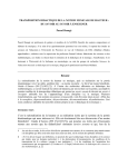
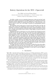
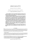
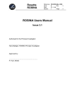
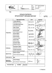
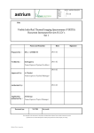
VEX MPS – supporting the Venus Express Mission Planning Concept Bruno Teixeira de Sousa VEGA IT GmbH at ESOC/ESA Robert-Bosch-Str. 5, D - 64293 Darmstadt, Germany [email protected] Andrea Accomazzo ESOC/ESA Robert-Bosch-Str. 5, D - 64293 Darmstadt, Germany [email protected] Ian Shaw and Robin Steel VEGA IT GmbH TIZ - Robert-Bosch-Str. 7 - 64293 Darmstadt, Germany [email protected], [email protected] Abstract Venus Express is a deep space mission with the following characteristics: • A considerable signal propagation delay on the communication link, • Visibility coverage during one third of the day from the prime ground station at Cebreros-Spain, • Support from additional ground stations during routine phase only for the Radio Science experiment, • Capability to collect a great amount of data that needs to be downloaded within the duration of a contact period, • Limited resources in terms of data link bandwidth, power consumption during eclipses and thermal load capability during pointing. These factors, among others, determine that operations have to be carried out autonomously from the Mission Timeline mechanism implemented in the on-board Data Management System. This in turn requires that any plan of observations for any particular time period has to be developed and validated well in advance. The approach to this plan development process consists of evolving it from an unrefined state to a more detailed planning state. In this way we are able to freeze spacecraft resources such as pointing, as early as possible to give the Venus Express Mission Operations Centre (VMOC) – composed of Flight Control (FCT) and Flight Dynamics (FDyn) teams – enough time to evaluate and correct the observation requests from the Venus Express Science Operation Centre (VSOC). To achieve this, a concept that utilises multiple planning cycles has been put in place. The VEX MPS (Mission Planning System) uses the planning and scheduling software kernel inherited from the ENVISAT and Mars Express Mission Planning Systems. However, in order to support the VEX Mission Planning concept for the routine operations phase, a number of new functionalities have been added to the software. A completely new software configuration has also been implemented. These allow the MPS to validate that the VEX mission operational rules and constraints are respected for any particular planning cycle, and to generate the corresponding commanding for both the Spacecraft and Ground Stations. This paper covers the VEX mission planning concept and the approach taken in modifying and configuring the MPS. VEX Planning Requirements Venus Express was launched on the 9th of November 2005 and was inserted in orbit around Venus on the 11th of April 2006. It is carrying seven different instruments that are operated daily around the planet. The mission is served by a single ground station for data downlink (Cebreros – Spain); additional stations (ESA New Norcia, Australia, and DSN Canberra and Goldstone) are scheduled during the routine phase for the Radio Science experiment. The mission entered its routine mission phase in mid-May 2006 after having achieved the target operational orbit (250x66000 km) around the planet. Payload operations are coordinated by the Venus Express Science Operations Centre (VSOC) – located in ESTEC, The Netherlands – which converts scientific measurement requirements into operation requests. These are further processed by the Venus Express Mission Operations Centre (VMOC), located in ESOC, Germany. The VMOC has the ultimate responsibility to ensure that all mission operations planned, and then actually conducted, do not violate any operational constraints and do not exceed the allocated resources of the space and the ground segment. In order to guarantee smooth, safe, but still optimised science operations a full process has been put in place between the involved centres for the planning of mission operations. Operational requests are processed and analysed early enough in the planning cycle to allow time to review them and eventually update them to match the actual capability of the mission. The ultimate aim of the planning exercise is to make full use of the “system”; such that the mission objectives are achieved in accordance with the available resources. The planning problem can be typically seen as an optimisation and control problem. The optimisation part is performed at science planning level by the VSOC, whilst the control part is executed by the VMOC. This paper deals with the planning problem given by this second part which can be classified in the following areas: Plan available resources according to the science needs and make them available for science planning (e.g. distribution of ground station contacts has to be adequate for requested operations) Process incoming operation requests (e.g. include payload operation requests in the planning) React to incoming operation requests with additional operations (e.g. dedicated ground station and spacecraft configurations in the case of radio science operation requests) Schedule spacecraft routine operations (e.g. management of the TTC subsystem, of the mass memory, orbit control manoeuvres, etc.) Verify that scheduled operations do not create any conflict (e.g. payload status vs. spacecraft status) Verify that scheduled operations do not violate any constraints (e.g. no Sun illumination on the instruments) Verify that scheduled operations are compatible with scheduled/available resources (e.g. mass memory overflow, or battery depletion) Put the operations request in place (e.g. generate commands for the spacecraft) The complexity, criticality, and the repetitive nature of the activities described above have driven the requirement for a software system to be used by the VMOC personnel. VEX Planning Concept The planning concept is based on an iterative process between the actors during which operations are iteratively refined and the required level of checking is performed. The process has been logically split into three steps: Long Term Planning: ground segment resources are allocated to the VSOC for science planning Medium Term Planning: science planning is prepared and then checked for feasibility Short Term Planning: overall planning is further refined, checked, and finally translated into operational commands for the spacecraft and the ground stations. GS usage + Bandwidth GS usage + Bandwidth LTP (6 months) OR + PTR checks OR + PTR checks OR + PTR checks ... MTP 1 Launch MTP2 STP 1 STP 2 VOI 1... 4 5 6 MTP n STP m STP 6 STP 3 ... STP 7 STP 4 0 ... STP 5 7 STP 8 8... months Figure 1 - Planning Cycles Each planning cycle is defined by processes and interfaces which are described hereafter. Long Term Planning This planning cycle covers a period of 6 months of operations, for which the VSOC defined a Science Activity Plan with the preferred observations for that season. Products are delivered to VSOC 6 months prior to start of the corresponding period, and include: The long term orbit file (ORVF) and the orbital event file (EVTF) from FDyn giving information about the reference orbit to be flown. The Downlink and Radio Science opportunities from the available Ground Stations (this file is called FECS) and TM Bit Rate bandwidth available (BRF) from the FCT. Required MPS Capabilities. To support this LTP cycle the FCT required from the Mission Planning System the capability to: Ingest orbit events and display a timeline of the planning skeleton. Process the Cebreros Ground Station Availability files, and based on this apply specific rules to derive additional events which determine when the Spacecraft should switch on its transmitters and the span of the data download windows over Cebreros contact passes. Determine Radio Science (RSI) window opportunities from the availability of New Norcia and DSN stations. Ingest the Orbit Correction Manoeuvres windows as planned by FDyn. 2 Validate that payload/subsystem mode transitions are made in a specific order (state diagram implementation)4. Check for incompatible payload/subsystem mode against pointing type or event (such as illumination)5. Derive new events from operations requests6. Generate resource (power/data) profiles over time. Manipulate existing profiles to generate new ones (typically the following operations need to be performed between profiles: addition, multiplication and integration over time) Check for profile threshold violations Raise warnings and display a layered timeline of events and operations; Profile plotting and printing capabilities. Finally all this information is collected in an agreed output form (the FECS mentioned above) and sent to VSOC for detailed science planning. Medium Term Planning This planning cycle covers one month of operations, and starts two months before the first operation takes place. VSOC produces a spacecraft pointing plan, and preliminary instruments operations requests. FDyn validates the pointing with respect to thermal and illumination constraints and spacecraft manoeuvring capability (wheel torque and momentum levels). If this is feasible, FDyn then generates the Sun aspect angles file (SAA) and medium term orbit and attitude event file (EVTP). These are a refinement of the EVTF but containing also attitude information such as payload Field of View (FOV) illumination events. The FCT checks then all products against operational rules and constraints. Required MPS Capabilities. To support this cycle the FCT required the following capabilities from the Mission Planning System: Ingest and process any event file in a standard format. Ingest and process of any type of operation requests1 (OR), as long as the operation exists as a sequence of commands in the mission database. Ingest and process the pointing file, containing pointing type blocks spanned over time2. Ingest the Sun Aspect Angle file (SAA) and interpolate between each sample to produce a one second resolution profile used to compute power generation from the Solar Arrays. Ingest the One Way Light Time file which allows taking this factor into account when scheduling spacecraft operations against ground events, or ground station scheduling against spacecraft events. Ingest the TM Bit Rate file to allow computation of data dumping profiles. Recognize particular operations as payload/subsystem modes and allocate default power consumption/data rate generation whenever the operation is requested3, thus building a profile over time. Alternatively use additional data supplied in the OR to build such resource profiles (socalled Z records). 1 POR for payloads, SOR for spacecraft generic operations and FDR for Flight Dynamics AOCS commanding 2 Pointing types include Earth, Nadir, Slew, Inertial, Wheel Off Loading, etc. 3 For example switching ON a payload will cause the power consumption to raise from zero to a positive value, and an amount of housekeeping data to be produced. Short Term Planning This planning cycle is performed weekly. VSOC generates final payload operations requests with all command parameters finalized. FDyn updates the frozen pointing file with latest orbit prediction data and generates a new updated SAA. FDyn also generates all the AOCS7 commanding8 corresponding to the pointing requested and creates the short term event file (EVTV) with AOCS mode change events and updated orbit/attitude prediction. FCT performs final check and generates Detailed Agenda Files (DAF - command stack for the spacecraft and schedule for the ground stations). The spacecraft commands upload strategy for the week is decided at this level and it is based on the total number of commands generated, the type of operations and the workload profile. Typically two or three uploads may be needed to avoid overloading the on-board Mission Timeline, but the overall concept can be pushed to have daily uploads. 4 For example payloads which require operations to be scheduled in a particular order are checked for correctness. 5 For example certain payloads shall be OFF when performing a Wheel Off Loading, or certain payloads shall be OFF if the FOV is illuminated. 6 For example when receiving a request for an RSI observation the corresponding start and end events are derived in order to be able to command the switching of the transmitters relative to them. When the SPICAV shutter is commanded derived events are generated to determine the status of the shutter and verify that it’s left closed at the end of an observation. 7 Attitude and Orbit Control System 8 Basically all the slews and inertial or dynamic pointing commands 3 Required MPS Capabilities. To support this cycle, in addition to the Medium Term capabilities referred above which are also required at this level for the final checking, also the following capabilities are required: To consolidate a fully checked and validated plan into a superseding and growing Master Plan from which all the schedules are to be generated. To produce, from that Master Plan, sets of schedules containing detailed commanding both for Spacecraft and Ground Station9, for a given time range, expressed in UTC or Orbit range (orbits start at Apocentre). To transmit these schedules to their respective destinations10. To calculate total number of commands and check for maximum commanding rate violations. The on-board time tagged queue (called Mission Timeline or MTL) mechanism cannot store more than 3000 commands and execute more than 20 commands per second. Planning Input: It is the task that retrieves and validates all planning products sent by external parties (VSOC and FDyn) via the FTS11. Master Operations: It is the task that ingests and processes event files and pointing timeline files, for a particular Orbit Range. It also has the capability to generate new events derived from the ingested ones (produced by FDyn, and other external parties), based on configurable rules12, and adding them to the Master Event Database (MPEF). The VEX MPS EKLOPS - The original software kernel The existing Mars Express Mission Planning System (MEX MPS) was used as the starting point for the Venus Express MPS, allowing a stable system to be rapidly provided under tight budgetary and schedule constraints. In turn, the core of the Mars Express MPS originated from a slimmed-down version of the ENVISAT Flight Operations Segment MPS – with generic elements being identified as potential candidates for reuse. In this section, we chart the development of the software during the Venus Express MPS implementation, and how the underlying planning kernel has been enhanced further by this process. This kernel, now referred to as EKLOPS (Enhanced Kernel Library for Operational Planning Systems), also forms the basis of several other planning developments being undertaken on behalf of the European Space Agency. Figure 1 – Original EKLOPS diagram Care was taken to provide solutions which did not rely on significant amounts of mission-specific code being written; EKLOPS almost exclusively uses a configuration database in order to implement mission specific functions. EKLOPS provided already the following capabilities: 11 9 Cebreros Ground Station is currently able to receive a schedule file containing a sequence of jobs, which almost completely automate the station operations 10 the Mission Control System for the spacecraft schedules, and the Ground Station Control Center (GFCC) for the GS schedule File Transfer System – task running in several nodes that pushes and pulls files on user demand. 12 for example, determining the event representing the instant that the transmitter should go ON based on the known event of the GS starting to track the spacecraft, by subtracting an offset and a OWLT (one way light time – to convert from ground to spacecraft time), 4 Plan Engine: It is the heart of the system: a task to build plans by ingesting and processing Operation Requests, building and visualizing resource profiles, checking for conflicts, visualizing the operations timeline, checking boundary conditions of plans. Scheduler: It is the task that uses the mission TC database to convert sequences from a plan into full command stacks (schedules) with respective parameters. Manual Request Editor: Basic ASCII editor to write Operations Requests. No validation or field editing capability. This has been greatly improved for VEX. DB test and DB editor: tasks to process XML configuration files into the MPS configuration database, and to visualize its contents. Technology: The Mission Planning System has been implemented on SUN ULTRA workstations, with C++ as implementation language. The design has been carried out with OOL methodologies, using UML with the Rational Rose tool on PCs. The implementation relies on the use of the following COTS: POST++ and XML are used for Database Management System; The ILOG Views library is used for the development of the HCI Components. The system is delivered as libraries of re-usable components. Especially the rule-based components of the MPS are delivered as a library of standard conditions and actions, which can be used to create rules. The new software functionalities In order to support the MPS configuration envisaged for VEX a number of new kernel functionalities have been implemented, namely: The capability to process Ground Station Availability files. These files follow a standard used both by DSN (NASA) and ESA stations. Each file essentially indicates, for a particular GS, the times at which the activity for a particular pass starts and ends, and the times that tracking will start and end. These times are converted into events within the MPS Master Event Database (MPEF). The capability to insert user events into the MPS Master Event database (MPEF). There are certain constraints that users might want to take into account when planning, for example we know that due to a limitation in our Solid State Mass Memory (SSMM) for specific periodic on-board times, which occur every few months, the storage of data has to be interrupted for a few seconds. This functionality allows the planner to ingest the time of this event and schedule the operation to stop and resume the storage around it. The capability to assign priorities to FDyn event files for different planning cycles. That is Short Term event files shall take precedence over Medium Term ones because Figure 2 - Inserting user events they contain a finer orbit determination, and Medium Term will take precedence over Long Term, because they contain additional data (for example contains payload illumination events, since in this cycle (MTP), the attitude profile is already known). The capability to output any configurable set of events from the database of the MPS into an event file. This was used to output the Communication and Radio Science windows for VSOC at long term planning (the FECS). The capability to ingest “other data” from Operations Requests (OR). Normally OR contain command sequences as defined in the MIB (Mission Information Database - with all Telemetry and Commands) for operating payloads. For Radio Science, where there is no real physical payload, the Science is performed using the platform transmitters. The commanding of the transmitters by FCT and scientist simultaneously is incompatible. Therefore the scientist uses the operation request to pass his desired start and end of observation, using a “dummy sequence”. The MPS when receiving such a dummy sequence generates an event within its database which indicates the type and timing of the observation. The events are used for scheduling the corresponding transmitter and GS commanding, in a combined, and conflict free manner. The capability to use either state based information to build a resource profile or use additional resource information supplied by the OR in the form of “Z record” parameters. When requesting a particular sequence to be scheduled the user can assign to that sequence an estimation of power consumption (ZP record) or data rate generation (ZD). The resource profile will then be built using these records as markers. In their absence the default value for that sequence/state is taken instead. 5 The capability to edit and generate Operations Requests (OR) with an appropriate editor. Operations requests follow an interface standard defined for the ROS/MEX/VEX missions which define a file structure with several editable fields. The editor uses the command sequence database (MIB) to simplify the task of entering sequences and to ensure their validity. It also checks that the events used for timing exist and are valid. It formats the output according to the standard. This is used by the FCT to schedule additional platform commanding. The capability to use the short code of command sequences as the key for identifying the sequence within the MPS database. The MEX approach was to use the Sequence description field, since the short code was changing with each new version. For VEX this short code is invariant and the unique identifier. This change represented a very deep and important change in the MPS architecture, since the MIB database (database of sequences and commands) had to be merged with the MPS configuration database to allow both approaches. The capability to have state models and automatic mode transitions after a specified time, for elements in the MPS database that are used to represent resource consumption. Typically a subset of an instrument’s command sequence is selected based on their impact on power consumption and data rate generation. The previous version of the MPS allowed the resource consumption to change only at commanding of a new sequence. Therefore, it was difficult to model behaviours like the VIRTIS payload cooling mode: after the corresponding sequence has been commanded a peak of power is seen for about 2 hours due to an electric motor being activated and then it drops a significant amount when the engine stops without any other sequence having been commanded. Also VIRTIS, consisting of 3 independent parts (the Main Electronics and the M and H channels), has sequences which influence the resource behaviour of only one or possibly more of the parts. Consequently the whole state diagram for VIRTIS has been decoupled from the sequences, and a state model for each of the parts has been put in place and combined to get the total payload resource usage behaviour. The capability to trigger warnings in the application logging area, based on the evolution of resource profiles. This allows the planner to visualise trends. For example the application will report the volume of the SSMM at crossing of various thresholds. The planner is interested in whether the maximum volume of the SSMM has been reached, but normally the limiting factor is actually the capability to download the data, which is changing with the distance to the Earth. In this case the trend of the volume becomes more interesting, rather than whether it has reached the maximum size. The capability to process the Master Event Database (MPEF, containing all the ingested FDyn and Ground Stations events, plus corresponding derived events), in a rule based approach. This approach was already used at the plan processing level, that is at the level when operations requests are processed: For each planning element (instrument or payload or resource), separate rules exist to ingest the OR, compute the mode models, compute resource profiles and perform checks on the profiles and modes. The planner can process all or only a subset of those rules, thus building his plan in several stages, depending on the data he has available for processing. The planner also saves time by only processing individual rules if his interested is in only in a particular part of the plan. The same rule based approach is used for the task of preparing the plan background, which involves the ingestion of external events and the derivation of new ones – the Master Ops. That is the planner can now choose which activities to perform to build his MPEF by selecting appropriate rules. Figure 3 - Master Ops - Rule based approach The capability to generate schedule files containing the commands to drive the ESA stations during a VEX pass. These commands are timed against the information obtained from the above mentioned GS Availability files. Currently the Cebreros Ground Station is automatically driven by the schedules generated from the VEX MPS without the need for operator intervention. The passes are initialized, the tracking and uplink are started and terminated and the pass finalized autonomously. In the near future the Radio Science passes of VEX over New Norcia and dedicated schedule of events for DSN (NASA stations) will also be produced by the MPS. The capability to generate schedules for a particular time range expressed in UTC. In the previous version of the MPS it was only possible to generate schedules for Orbit 6 ranges. With this new functionality the start and end times of the schedule can be carefully chosen not to split any operations. The orbit boundaries, being the Apocenter, often coincides with on-going observation or pass activities which would be split into different DAF. If one of the DAF for some reason is not uploaded13 then the spacecraft could be left in an inconsistent state. The “Operational Rules and Constraints” and the VEX MPS configuration A set of routine mission operational rules and constraints has been identified in a document (the ORCD) by the FCT based on the Spacecraft User Manual as laid down by the manufacturer. These rules and constraints drive the checks and modelling that the MPS makes in order to validate a particular plan of operations. Therefore this document and the MPS configuration are very close coupled. They are in fact one and the same baseline. They are maintained together under configuration control, and any changes to the document are reflected in the configuration and vice-versa. Master Event Database. The first part of the document concerns how the external environment (orbit, attitude and GS activity) is represented within the MPS. The inputs that have to be ingested are identified, such as: the several FDyn event files14; the FDyn pointing timeline (FTLV); and the GS availability files (ESAF and DSN SAF). The valid types of spacecraft pointing attitude are also identified, such as EARTH, NADIR, INERTIAL, etc.; It is described how new events should be derived, such as: the instant the transmitter should be switched ON or OFF, relative to the time the GS will start or end tracking respectively; the instant at which the data downlink should start or end relative to the time the transmitter goes ON or OFF; the Radio Science windows relative to the start and end of NNO or Canberra passes. The subset of events that needs to be output at Long Term cycle for the VSOC is defined. This is the data that is processed by the Master Operations task within the MPS. Element modelling and conflict checking. A second part addresses how the different elements of the spacecraft, which are relevant15 for planning, are modelled, based on the commanding profile as received from Operations Requests (OR), in order to determine conflicts. The transmitter status has significant impact on power; the type of pointing will influence the thermal power consumption16; each payload will have a power consumption and data rate generation profile depending on the operating mode. The conflict checks are also defined, such as: Some payloads shall be OFF when the spacecraft is performing a Wheel Offloading or an Orbit Correction Manoeuvre. Some payloads shall be OFF or their shutters closed when direct sun illumination occurs (event identified by Flight Dynamics based on the attitude profile) Figure 4 - Payload illumination conflict detection Some payloads shall be OFF at the end of an observation. Some payloads shall have thermal control enabled prior to an observation. Some payloads shall be commanded according to particular command sequence patterns. The High Speed Link (bus that gives some payloads direct access to the SSMM) shall not be active when the SSMM is being down linked to Earth. The spacecraft shall be in EARTH pointing mode during a communications window 13 For example GS unavailable due to failure EVTF, EVTP and EVTV for long, medium and short term cycles respectively as mentioned before 15 The relevant elements are those which affect resource usage, such as power consumption and data rate generation. 14 16 Pointing with illumination on radiating faces will cause the spacecraft to warm-up and the heater consumption to decrease, and vice-versa. 7 The spacecraft shall only switch on the transmitter in a cooling attitude17. RSI observations shall only be performed within RSI passes with NNO or Canberra. The processing of element modelling and conflict checking is realized within the MPS Planning Engine task. and exceeded limits. An exceeded limit causes the operation being planned to be not accepted. The spacecraft will detect a battery under charge condition and react with Safe Mode. Ageing factor of the battery and Battery Regulator efficiency are also taken into account. Resource Management. A third part concerns the resource usage profiles generated and the checks performed on them: The total rate profile on the spacecraft data bus (OBDH) is calculated and checked against critical and excessive thresholds. Exceeding traffic on the bus will lead to buffering of data and underperformance of the data handling subsystem. The amount of data in each science file allocated to a payload, in the memory (SSMM), is calculated and checked against overflow. The MPS will raise the warning it is up to the scientists to accept the risk or modify their observation profile. The total SSMM volume is calculated by integrating the total platform generated data rate (OBDH plus High Speed link) subtracted from the available bandwidth for downlink during passes over time and checked against the capability to downlink within the next pass opportunities. Once more it is the scientist’s call to accept the risk of eventual data loss; once the SSMM overflows, old data starts to be overwritten. The power generated by the solar arrays is calculated as a function of the angle of the sun to the surface of the panels over time, and of the distance of Venus to the Sun, and masked by periods of eclipse. Power regulator efficiency is also taken into account. The total power consumption profile of the platform is calculated by adding the average consumption of the permanently ON instruments18, with the Transmitter and Payload consumption (as a function of their modes), with the Thermal Consumption (as a function of pointing) and taking also into account harness losses; and then checked against the maximum power delivery capability of the Power Distribution Unit (PDU). No operations scenario where this threshold is exceeded can be accepted. It would result in a main bus under voltage condition that would bring the spacecraft to Safe Mode. The batteries power flow profile is calculated taking into account that the batteries will supply (discharge) the difference between the PDU demand and the solar array available power, and when discharged with enough solar power being produced will charge at a fixed rate. The Depth of Discharge (DoD) results from the integration of the charge and discharge rate, and is checked for critical Figure 5 - Power consumption profile Likewise, the above resource management is performed by the Plan Engine task within the MPS. 17 18 No sun on radiating faces Such as CDMU, SSMM, AOCS, etc. Scheduling. Finally the last part concerns the generation of commands for the spacecraft, which is performed by the Scheduler task, which expands the requested sequences into stacks of time-tagged commands, with their respective parameters, using the mission TC database for the conversion. Here the constraint that the Mission Timeline mechanism on-board is not be able to process more than 20 commands per second is checked. An additional constraint is the maximum capacity of the Mission Timeline (mechanism that executes the commands - MTL) which can hold up to 3000 commands. Currently the MPS has no memory or knowledge of the content of the on-board command queue and of the uplink strategy, and cannot therefore check for this constraint. This will be an area for future development. The MPS does report on the size of each generated command file19 allowing the planner to decide on the uplink strategy according to the current capacity of the MTL. In order to address completely the MPS configuration the ORCD also mentions the application Timeline display 19 Also known as DAF – Detailed Agenda File 8 configuration, and the default states for all payload modes, and resources. All the above mentioned modelling is implemented in the MPS using so-called (internally) “rules”. These “rules” are defined in XML configuration files which represent the interface with the application kernel, instantiating calls to kernel functions20 and passing the necessary parameters so that the specified models are achieved. The files are later converted into a database that the application is able to access faster. Through the MPS application MMI one can activate and de-activate the rules that are to be processed, but one cannot modify the rule itself, other than by editing the XML configuration files, and re-generating the database. In the future this is an area where more development is welcome, such as flexible editors that allow the users to define their problem domain and models and checks and then having them directly published for use by the application. The MPS validation and the end to end testing Three formal deliveries were made prior to entering operations and additional intermediate incremental deliveries with patches for particular problems were also delivered. A formal system integration test plan was developed and executed and two end to end tests have been performed involving all the interfaces21, allowing the MPS to be extensively exercised prior to entering operations. The end to end testing has proven to be the most profitable and rewarding method, since emulation of a near-real-time operations scenario introduced the heaviest load on the MPS, allowing detection of problems that otherwise would not have been detected with functional testing. It also exercised the interfaces allowing the different systems involved to align and correct deficiencies. Approximately 150 Software Problem Reports were raised and fixed by the developers, and approximately 100 configuration or planning products changes were raised internally. All system and integration level testing was performed by the FCT, and development management shared with the Data Systems division. Software problems were managed with a web-based tool from the Data Systems Division (e-log). Internal changes were managed with the quality supported Anomaly Report Tool (ARTS) and products maintained under configuration control with the Clear Case repository. 20 These functions include: function to ingest and parse a particular type of file; function to check a mode against another and give warning; to sum a number of profiles; to multiply two profiles; to integrate a profile over time; derive an event from another with offset; and many others. 21 VSOC – VEX Science Operations Center; and Flight Dynamics. The Future needs The current system is a significant evolution from the systems already used in ESOC for other missions in the sense that it encompasses several functions which are normally performed outside the classical Mission Planning System. Further to this the system has been extended not only to cover the spacecraft activities but also the ground station activities. Nevertheless there are some areas where the system performance needs to be improved or new functionalities need to be added. New functionalities required in the immediate future Among the functionalities and configuration updates required for the immediate future one can envisage the following: New conflict checks and updated models. Since the spacecraft has been operated in a routine manner we have come to understand some constraints differently, this and the need to increase flexibility in constraints that are currently too strict, created the need to re-consider some of the current implementations. In this category fall the checks of Transponder usage outside of ground contact configuration, the modelling of packet stores, and the modelling of some payloads operations. NNO RSI passes scheduling. As for Cebreros, the NNO ground station will soon be ready to receive schedules for automatic commanding. DSN station key file generation. In the same way the DSN stations require a dedicated file to schedule their activities during RSI observations. Automatic synchronized Spacecraft/Ground Station Bit Rate changes. This functionality will allow setting of the Bit rate in ground station commands according to the current spacecraft settings. Reporting Capability At the reporting level a number of capabilities are lacking which will be addressed, such as: Generation of planning session reports and meaningful summaries. This should provide evidence of the activities performed by the planner and allow the user to trace eventual deficiencies in the planning process that could result in the execution of incorrect operations (e.g.. missing operations). Generation of Pass Sheets, to instruct the SPACONs22 on what is to be uploaded and provide pass-relevant timing information (i.e. begin and end of tracking, carrier up and 22 Spacecraft Controllers – The person that monitors and commands the spacecraft during a ground contact period. 9 down, when to expect eclipses and star-tracker occultation events, etc.) Exporting of resource profiles to worksheet format to be manipulated and analysed by external tools (ex. Excel). Displaying events and activities in a chronological list format for quick review of timeline. Schedule Generation management Currently the MPS has no memory or record of what has actually been generated/uploaded/commanded to the spacecraft. In this area it could be envisaged that in the future the MPS would be able to: keep track of deployed commands to avoid repetitions or overlaps; and advise the planner on a generation or upload strategy for commands, taking also into account the command storage capability on-board. Linked to this is also the capability to recognize that the removal of an operation from the plan implies the deletion of the respective commands in case they are already on-board. The VEX MPS in numbers Some statistics about the operational usage of this system at the time of the final update of this paper: - 7 Medium Term cycles fully planned with several conflicts early detected and addressed; - 20 Short Term cycles fully planned with more than 80.000 commands generated and uploaded to the spacecraft and 2.000 commands for the ground station; - An average 4/5 hours required by the FCT for planning each week of operations (STP), and 2/3 hours for each monthly planning session (MTP); - Approximately 220 Gbits of science data recorded and downloaded from Venus to the ground over approximate 1400 hours of contact. - One observation missed out of approximate 600 commanded, due to human error in planning process. No observation missed related to an MPS fault. - 0 Spacecraft Safe Modes caused by planning errors. - 0 dedicated planners in the VEX FCT. The task is shared among all the 8 engineers and analyst on a shift basis, and represents 5% of each one’s total amount of work (approximately 10 hours every 5 weeks are dedicated to planning activities). This represented a major achievement and mile-stone for the Mission Operations of VEX. The VEX Flight Operations Plan was also ready to support the planning activities as envisaged in the planning concept with the usage of the MPS, and all the members of VEX FCT have been trained for using the tool and accomplishing with success the operations planning. The MPS has shown an advanced level of maturity and stability as a result of the long period of testing and finetuning. The plan for the first week was produced by one person within one working day, and a faultless schedule was generated, proving the efficiency and effectiveness of the tool. Work is still on-going to improve its performance; currently some of the tasks that the planner is required to perform with the tool can be accelerated (i.e. starting up of applications, creation and processing of plans, saving and committing plans). New functionality is already envisaged to upgrade the tool to provide a greater level of flexibility and planning capability. As the FCT gathers experience, the planning concept will also evolve to better correspond to the missions specifics and the MPS will evolve with it. References [1] I.Shaw, M.Niézette et al., Mission Planning for Europe's latest earth observer, Proc. Int. Sym. Ground Systems for Space Mission Operations. SPACEOPS 2000, Toulouse, June 2000. [2] I.Shaw, M.Niézette et al., A new world for the Generic Mission Planning System, Proc. Int. Sym. Ground Systems for Space Mission Operations. SPACEOPS 2002, Houston, Texas, October 2002 [3] A.Accomazzo. 2005. VENUS EXPRESS Mission Planning Concept, ESA internal document. [4] B.Sousa, I.Dauvin, et al. 2006. VENUS EXPRESS Mission Planning System Operations Rules and Constraints Document, ESA internal document. [5] B.Sousa, A.Accomazzo, 2005. VENUS EXPRESS MPS User Requirements Document, ESA internal document. [6] I.Shaw, R. Steel, et al. 2006. VENUS EXPRESS Mission Planning System Software User Manual, ESA internal document Conclusion The VEX MPS successfully entered operations on the beginning of May 2006. In the first week of routine operations in Venus, VEX was already being guided with the stacks of commands generated and validated by the MPS. 10