1
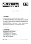
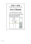
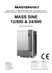
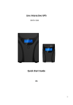
Line-Interactive Uninterruptible Power Supply Unit 650 VA USER’S MANUAL MNL105-650VA-T INTegral Line-Interactive Uninterruptible Power Supply Unit—650 VA Power Innovations 1 READ THIS MANUAL CAREFULLY SAVE ALL INSTRUCTIONS This manual contains important information that you will need to operate the UPS safely and efficiently. Please read all instructions carefully before installing or operating equipment. Keep this manual handy for easy reference. ELECTRICAL WARNINGS Read and follow installation instructions carefully before operating. Applying information contained in this manual to any other product may cause injury. The INTegral is registered for sale by Power Innovations International, Inc. This manual may have been received with other products or instructional materials. If additional products or instructional materials have been ordered but have not been received, contact your reseller. © Copyright 2015 Power Innovations International, Inc.; American, Fork, UT, USA. All rights reserved. The Standard for Perfect, Dependable Power Version 1.0 2 Power Innovations INTegral Line-Interactive Uninterruptible Power Supply—650 VA Table of Contents 1.1—Congratulations on Your Purchase ................................................................................................................................ 4 1.1.1—Key Features ............................................................................................................................................................ 4 1.2—Using this Manual ........................................................................................................................................................... 5 1.2.1—Manual Conventions ................................................................................................................................................ 5 1.2.1.1—Additional Advice ............................................................................................................................................... 5 1.2.1.2—Type Conventions ............................................................................................................................................. 5 1.3—Power Flow ..................................................................................................................................................................... 6 1.3.1—Normal Power Mode ................................................................................................................................................ 6 1.3.2—Battery Backup Mode............................................................................................................................................... 7 2.1—Receiving ........................................................................................................................................................................ 8 2.2—Transporting ................................................................................................................................................................... 8 3.1—Placing Systems Correctly.............................................................................................................................................. 9 3.1.1—Environmental Concerns.......................................................................................................................................... 9 3.1.2—System Ventilation ................................................................................................................................................. 10 3.1.3—Orienting the System Correctly .............................................................................................................................. 10 3.2—Connecting Systems..................................................................................................................................................... 10 4.1—System Power-ON ........................................................................................................................................................ 13 4.2—Cold Start ...................................................................................................................................................................... 14 4.3—Running on Battery Power............................................................................................................................................ 14 4.4—No Outputs Connected ................................................................................................................................................. 14 4.5—System Power OFF ...................................................................................................................................................... 14 4.5.1—While Connected to Input....................................................................................................................................... 14 4.5.2—While in Battery (Backup) Mode ............................................................................................................................ 14 4.6—Storing the System ....................................................................................................................................................... 14 5.1—Maintenance ................................................................................................................................................................. 16 5.2—Troubleshooting Tables ................................................................................................................................................ 16 5.2.1—Utility Power Functioning ....................................................................................................................................... 16 5.2.2—Utility Power Failing ............................................................................................................................................... 17 7.1—Limited Warranty .......................................................................................................................................................... 20 7.1.1—Shipment and Power-up Dates .............................................................................................................................. 20 7.1.2—Warranty Inclusions ............................................................................................................................................... 20 7.2—Part Replacement and Servicing .................................................................................................................................. 20 7.2.1—Restrictions ............................................................................................................................................................ 20 7.2.1.1—Unauthorized Service or Removed Serial Number ......................................................................................... 20 7.2.1.2—Product Misuse or Abuse ................................................................................................................................ 20 7.2.2—Legal Rights ........................................................................................................................................................... 20 7.2.3—Limitations of Coverage ......................................................................................................................................... 20 7.2.4—Proof of Purchase .................................................................................................................................................. 21 7.3—Warranty Claims ........................................................................................................................................................... 21 7.3.1—On-site Visits .......................................................................................................................................................... 21 7.3.2—Product Shipping .................................................................................................................................................... 21 7.3.2.1—Prior Approval.................................................................................................................................................. 21 7.4—Limitation of Remedies ................................................................................................................................................. 21 8.1—Information to Provide .................................................................................................................................................. 22 8.2—Returning Equipment .................................................................................................................................................... 22 8.3—Replacement Assemblies ............................................................................................................................................. 22 INTegral Line-Interactive Uninterruptible Power Supply Unit—650 VA Power Innovations 3 1—Introduction 1.1—Congratulations on Your Purchase Thank you for purchasing Power Innovations’ INTegral Line-Interactive Power Supply Unit. Power Innovations believes in the efficiency and durability of its products. The company hopes that this product will serve you well for an extended period of time. Office equipment needs reliable, clean power. The Uninterruptible Power System (UPS) is designed to meet all computer, server and automated office equipment needs with a compact, quiet unit that operates efficiently and provides multiple interface options. To choose the INTegral 650LED as your equipment protector is a wise investment because it supplies reliable, pure and stable power at an affordable price. 1.1.1—Key Features Line-interactive sine-wave topology Intelligent charger Compact size Intelligent fan speed control Battery cold start Figures 1 and 2: Front and Rear Features of the 650 kVA INTegral System 4 Power Innovations INTegral Line-Interactive Uninterruptible Power Supply—650 VA 1.2—Using this Manual Read and understand this manual to make installing and operating the system as easy as possible. This manual will show how to safely work the INTegral. Refer to the Table of Contents for a chapter-based guide. 1.2.1—Manual Conventions 1.2.1.1—ADDITIONAL ADVICE This manual will occasionally provide additional advice. When it is provided, this information will be enclosed by a set of lines to separate it from the rest of the text, like this: This text does not belong with the rest. Some of the information is very important, while other information may be good to know. To show the importance of each piece of information, the following symbols and formatting conventions are used: WARNINGS Denotes advice that, if not followed, could cause severe bodily harm or death due to electrical shock. Denotes advice that, if not followed, could cause severe bodily harm or death due to other types of injury. Cautions Offers advice that, if not followed, may harm equipment or indirectly cause physical hazards. Notes Offers practical advice that may be helpful, but can be disregarded. 1.2.1.2—TYPE CONVENTIONS Italic type—Used for some product acronyms Bold type—Used to caption figures Other noteworthy type conventions used in this manual include: INTegral Line-Interactive Uninterruptible Power Supply Unit—650 VA Power Innovations 5 Italic type—Used to refer readers to another chapter or section. Bold type—Used to reference figures included on the same or following pages. 1.3—Power Flow In the INTegral Line-Interactive UPS System, AC utility power flows through two main loops: the AC loop and the battery charging loop (Figure 3). Figure 3: Power Flow for INTegral Line-interactive system 1.3.1—Normal Power Mode When functioning normally, the system will power the load and charge batteries to operate when utility power is unstable. This method of battery backup provides a cost-effective means of providing reliable, uninterruptible power and increasing UPS efficiency to save you money. In the AC loop, the power comes from AC utility input such as a wall outlet and passes through a static switch to support power to the load so long as power is clean and reliable (Figure 4). In the battery charging loop, an AC/DC converter changes AC utility input voltage into DC power, which charges the system’s batteries. Figure 4: Power flow during Normal Power Mode 6 Power Innovations INTegral Line-Interactive Uninterruptible Power Supply—650 VA 1.3.2—Battery Backup Mode In this mode, AC output comes from the battery. Battery voltage is boosted and converted to create a clean, stable AC sine wave to power even the most sensitive equipment. Power will pass from the battery through the DC/DC converter, DC/AC inverter, and static switch to provide output for the full length of the battery charge. Actual battery backup time will vary, depending upon initial battery charge and the current load percentage. See 6—Specifications for backup time estimates. Figure 5: Power flow during Battery Backup Mode INTegral Line-Interactive Uninterruptible Power Supply Unit—650 VA Power Innovations 7 2—Receiving and Transporting Systems Because the UPS System supplies power, it must be handled carefully. For better product performance and to avoid injuries, follow the cautions below. 2.1—Receiving Inspect the packaging carton and its contents for damage. If the contents have been damaged, notify your reseller immediately. After removing the system, keep its packaging in a safe place for future use. 2.2—Transporting Power the system down and disconnect all power cables before moving the system. While moving the system, handle it carefully. The combined weight of the unit and its batteries can be significant. It is recommended that the system be transported in the original packaging. ELECTRICAL WARNING DO NOT transport the system with power cables still attached. Failure to heed this warning could cause accidental electrical shock or death by electrocution. Cautions Save the original packaging and use it for transport. Using the correct packaging will prevent unnecessary harm to the system. Note With concerns about the manufacture or shipping of this product or its components, please contact: Power Innovations International, Inc. Tel: (801) 785-4123 Fax: (801) 785-6999 E-mail: [email protected] 8 Power Innovations INTegral Line-Interactive Uninterruptible Power Supply—650 VA 3—Installing Systems 3.1—Placing Systems Correctly 3.1.1—Environmental Concerns Install the system with the correct side facing up and on a level, even surface. The INTegral will work its best if installed in a dry environment out of rain, snow, wind, and direct sunlight. Clutter, flammable gases, and corrosive liquids may damage the unit or even constitute severe operating hazards. Table 1: Correctly Placing the System Environment Surface Grade Heat Temperature Ideal Placement Level Surface Far from direct solar or artificial heat 32–104 °F (0–50 °C) Ventilation Space Cleanliness Orientation Space around system No dust or clutter Right side up Avoid Incline Heat sources or direct sunlight Location cooler than 32 °F (0°C) or hotter than 104 °F (50°C) Tight spaces Dusty or cluttered places Upside down or on its side Cautions Never place this system: Upside down or on an incline. In direct sunlight or weather. Near any source of natural or artificial heat. With less than 1” in. of ventilation room on all sides with visible ventilation holes. Avoid locations where the system: Could be exposed to flammable gases or corrosive liquids. Will be cooler than 32°F (0°C) or hotter than 104°F (50°C). Will be exposed to clutter or objects that could block ventilation openings. Cannot ventilate. INTegral Line-Interactive Uninterruptible Power Supply Unit—650 VA Power Innovations 9 3.1.2—System Ventilation To ensure adequate ventilation, measure the place where the system will be placed to be sure that it will fit comfortably. Leaving space around the system will allow it to ventilate more efficiently. 3.1.3—Orienting the System Correctly This system is a tower model (indicated by the T following the model type), meaning that the unit is meant to operate in tower configuration. To correctly place a tower system, set it on its vertical bottom end. Placing the system on its sides, front, or rear, will inhibit UPS operation. For more information about socket locations, refer to 1.1.1—Key Features. Figures 6 and 7: Ventilation clearances for the INTegral system 3.2—Connecting Systems For product keys showing the socket locations and other interface connection options located on the casing, see 1.1.1— Key Features. 1 Connect the UPS input to an AC utility source such as a standard wall outlet. Be sure that the outlet has the appropriate power capacity. 2 To connect the system to the device it will be powering, plug one end of the device’s power cord into the INTegral output socket. 10 Power Innovations INTegral Line-Interactive Uninterruptible Power Supply—650 VA Note The output slot connects only to socket-type cords. 3 Connect the other end of the device’s power cord into the device to be powered. 4 Connect the monitoring UPQsoft cord to the USB port or install the UPQNet-Agent9 Mini. After the hardware has been connected to the port, the monitoring software is ready to be connected to a computer and configured. Additional Manual Connect the unit to the computer to monitor it. If UPQsoft or UPQNet-Agent9 has been ordered, another manual will be included. 3.2.1—Prestart Checklist The UPS is positioned correctly. The input cord is secured. The rated input voltage from the wall socket falls within the unit’s safe operating range. System cables are placed carefully to minimize stepping and tripping hazards. INTegral Line-Interactive Uninterruptible Power Supply Unit—650 VA 11 Power Innovations This page intentionally left blank. 4—Operating the System While operating the system, be sure that it has adequate ventilation space. Be sure the operating area is left free of clutter or other objects that may block ventilation slots. Avoid placing liquids or flammable gases near the system during operation. Keep the system far away from sources of natural or artificial heat (ie. heaters, direct sunlight) and make sure the system is not overloaded. During routine system operation: Ensure that no liquids of any kind enter the UPS system. Do not block off ventilation openings in the system’s casing. Keep objects from within four (4) inches of all visible ventilation holes in the UPS. The added space helps the system ventilate. Do not disconnect the main cable or unplug the system from the wall outlet unless all breakers have been turned OFF. This will cause the system to switch to backup mode and drain the batteries. ELECTRICAL WARNING Disregarding the preceding advice may directly cause or contribute to injury. Caution Disregarding the preceding advice may harm the system and void the system warranty. 4.1—System Power-ON Once the UPS is connected to the power source, the LED light will blink, indicating that the inverter can be switched ON. Press the LED light button for two (2) seconds to turn ON the UPS. As the UPS turns ON, the green LED will illuminate solidly and the buzzer will beep twice. Note If the button is only briefly pressed, the light will illuminate for about five (5) seconds and then turn OFF again. The system will ventilate but not operate fully. This limited operation mode protects the system from accidentally being turned ON as it is jostled or bumped. Make sure to press the button for at least two (2) seconds. When the system is ON, it will beep twice. INTegral Line-Interactive Uninterruptible Power Supply Unit—650 VA Power Innovations 13 4.2—Cold Start When the system is powered up using only battery power, the LED light will be turned OFF until the button is pressed. To cold-start the system, press the button while the system is not connected to an AC input source. The light will illuminate, and the system will beep twice to indicate that it has been started. After one (1) second, the system will beep a third time and the green LED light will flash. These signs indicate that no utility source has been connected and the system has been started using battery power. 4.3—Running on Battery Power When the UPS is ON and in Battery (Backup) mode, the UPS will beep every four (4) seconds. Note The UPS buzzer will be enabled automatically in severe cases such as overload, overheat, or lowbattery conditions. 4.4—No Outputs Connected When power is not being transferred to the load, the UPS will beep and the green light will flash. For more information, see 5—Troubleshooting. 4.5—System Power OFF Press the LED light button for two (2) seconds. The system will beep twice as it turns OFF. 4.5.1—While Connected to Input The UPS will be disconnected from the output, with the green LED light blinking until the AC source has been disconnected. 4.5.2—While in Battery (Backup) Mode If the system has been powered OFF, the light will turn OFF. 4.6—Storing the System Disconnect input power from the unit’s rear panel if it will not be used for extended periods of time. If the UPS is stored for longer than two months, plug it back into a power supply for at least 24 hours to fully restore the battery charge before use. 14 Power Innovations INTegral Line-Interactive Uninterruptible Power Supply—650 VA ELECTRICAL WARNING Keep the unit clean only by dusting it with a dry cloth. DO NOT get it overly moist, or physical damage may result. Caution If the UPS will be stored for long periods of time, the battery must be charged once for every 60 days of storage. INTegral Line-Interactive Uninterruptible Power Supply Unit—650 VA Power Innovations 15 5—Maintenance and Troubleshooting 5.1—Maintenance Very little user maintenance is required. The system has no user-serviceable internal parts. If the system gets dirty, clean it by dusting it with a dry cloth or can of air duster while the system is OFF. DO NOT wipe down the system with a wet cloth. 5.2—Troubleshooting Tables If the buzzer begins to beep and the light begins to blink although utility power is normal, use the table directly below. If AC input power is failing, use the second table. ELECTRICAL WARNING This system should not be serviced except by authorized individuals. Opening the case could cause accidental injury or death due to the enclosed batteries. Follow the troubleshooting guide. If troubleshooting does not fix the problem, call Power Innovations. 5.2.1—Utility Power Functioning Scenario AC utility power is normal. UPS is running normally. Buzzer is continual. AC utility power is normal, but UPS is overloaded. LED blinks and buzzer beeps every second. AC utility power is normal. LED blinks and buzzer beeps every half-second. AC utility power is normal. LED blinks and buzzer beeps continuously. 16 Power Innovations Possible Cause Fan is damaged. Try Replacing the fan. Unknown. Restarting the unit. Contacting Power Innovations. System overload between 100% and 125%. System overload between 125% and 150%. System overload greater than 150%. Reducing the critical load to less than 100%. INTegral Line-Interactive Uninterruptible Power Supply—650 VA 5.2.2—Utility Power Failing Scenario AC utility power fails. The battery powers the load. Buzzer beeps every four (4) seconds. Possible Cause AC utility power failure. AC utility power fails. UPS is in battery backup mode. Buzzer beeps every second. AC utility power fails. UPS has shut down automatically. Battery power is approaching low levels. AC input may not be connected correctly. Battery has run out. INTegral Line-Interactive Uninterruptible Power Supply Unit—650 VA Try Reducing the critical load to extend backup time. Checking the input rate. Checking power connection UPS will shut down automatically. Save data or disconnect loads soon. UPS will restart when AC utility power is restored. Power Innovations 17 6—Specifications Capacity (VA/Watt) 650 VA/406W Model Type Input Voltage Range Output Voltage Regulation Frequency Regulation Efficiency Short-Circuit Protection DC Start Transfer Time Tower Nominal Voltage Acceptable Voltage Range Frequency Boost Transfer Boost Return Buck Transfer Buck Return Low Voltage Transfer Low Voltage Return High Voltage Transfer High Voltage Return Voltage Line Mode Battery Mode Line Mode Battery Mode Power Factor Wave Form Line Mode Battery Mode Line Mode Battery Mode Cold Start Typical Battery Voltage 100/110/115/120 VAC 85~150 VAC 45 Hz ~ 70 Hz Auto-sensing 85/94/97.8/102 VAC ± 2% 90/99/102.8/107 VAC ± 2% 115/126/132/132 VAC ± 2% 110/121/127/127 VAC ± 2% 74/81/85/89 VAC ± 2% 79/86/90/94 VAC ± 2% 130/143/150/150 VAC ± 2% 125/138/145/145 VAC ± 2% 100/110/115/120 VAC ±15% < 3% RMS for entire battery voltage range Synchronize to AC Mains 60 Hz ± 0.1 Hz 0.625 Pure Sine wave > 98% > 80% Circuit Breaker Electronic Circuit Yes < 4 ms. 12VDC Battery Control Panel Audible Alarm Communication Interfaces Environment Physical Safety Conformance 18 Power Innovations Battery Type Battery Quantity Backup Time: 50% Load Backup Time: 100% Load Recharging current LED display Battery Mode Low Battery UPS Fault Overload Standard Operation Temperature Relative Humidity Audible Noise (WxHxD) mm (WxHxD) in Net Weight (kgs) Net Weight (lbs) NEMA Outlets (100/110/115/120 VAC) Safety Standard EMC Marks 9AH (8.5AH) 1 pce > 6:30 >1:30 0.1C Normal (Green) Warning (Blinking) Beeping every 4 seconds Beeping every second Beeping continuously Beeping twice per second USB 0–40 °C (32–104 °F) 0–95% non-condensing Less than 55 dBA (at 1m) 115*322*130 4 17/32 x 12 43/64 x 5 1./8 6.2 13 lbs 10.7 oz 3+1 (Option) EN62040-1-1 EN62040-2 CE INTegral Line-Interactive Uninterruptible Power Supply—650 VA This page intentionally left blank. INTegral Line-Interactive Uninterruptible Power Supply Unit—650 VA Power Innovations 19 7—Legal Information 7.1—Limited Warranty Power Innovations International, Inc., (hereafter “Power Innovations”) warrants this product to be free from defects in material and workmanship for a period of one year from the purchase date. 7.1.1—Shipment and Purchase Date The purchase date will be determined only from the sales receipt or other proof of purchase provided by Power Innovations or other resellers. 7.1.2—Warranty Inclusions The warranty also includes twelve-month coverage on parts only. 7.2—Part Replacement and Servicing If any part or portion of the Power Innovations product fails to conform to the Warranty within the Warranty period, Power Innovations, at its option, will furnish new or factory remanufactured products for repair or replacement of that portion or part. Replacement parts or unit may be new or refurbished and will meet specifications of the original parts or unit. 7.2.1—Restrictions 7.2.1.1—UNAUTHORIZED SERVICE OR REMOVED SERIAL NUMBER The product must not have been previously altered, repaired, or serviced by anyone other than a service facility authorized by Power Innovations to render such service, and the serial number of the product must not have been altered or removed. 7.2.1.2—PRODUCT MISUSE OR ABUSE In order to be covered by this warranty, the product will not have been subjected to accident, misuse or abuse, or operated contrary to the instructions contained in the User’s Manual. Any such conditions will void this warranty and the purchaser assumes all the expenses associated with the on-site visit, including travel expenses, parts and labor. 7.2.2—Legal Rights This warranty gives you specific legal rights. You may also have other rights which vary from state to state. 7.2.3—Limitations of Coverage 20 This warranty is limited to the original purchaser of the product and is not transferable. This warranty covers only Power Innovations-supplied components. Service required as a result of third-party components is not covered under this warranty. Power Innovations INTegral Line-Interactive Uninterruptible Power Supply—650 VA 7.2.4—Proof of Purchase Proof of purchase will be required by Power Innovations to substantiate date of purchase. Such proof of purchase must be an original bill of sale or receipt containing name and address of seller, purchaser, and the serial number of the product. 7.3—Warranty Claims Within a reasonable time, but in no case to exceed thirty (30) days, after discovery of a defect, the purchaser shall contact Power Innovations at 801-785-4123. Subject to the limitations specified herein, a Power Innovations service representative will determine the appropriate course of action to repair the non-conforming product warranted hereunder. 7.3.1—On-site Visits If it is determined that an on-site visit is needed to resolve the issue, Power Innovations will recommend a service visit by a Power Innovations representative or authorized service representative. It is the responsibility of the purchaser to cover the expenses of an on-site visit, excepting the cost of warrantied parts. Service contracts that include the cost of on-site visits can be purchased through Power Innovations Customer Service department. 7.3.2—Product Shipping If it is determined that the product or a part must be shipped back to the manufacturer for repair, the purchaser will assume liability and pay for shipping to Power Innovations or an authorized service center. Power Innovations or an authorized service center will pay for shipping to return the repaired product to the customer. 7.3.2.1—PRIOR APPROVAL All products returned for service MUST have prior approval and an RMA number. 7.4—Limitation of Remedies Power Innovations’ entire liability and the User’s exclusive remedy will be repair or replacement of the unit if all conditions described under “Limited Warranty” have been met. In no event will Power Innovations be liable for indirect, special, incidental, consequential, or exemplary damages of any kind whatsoever arising out of the use of this unit, including without limitation, lost profits, business interruption, or loss of data, whether any claim is based upon theories of contract, negligence, strict liability, tort, or otherwise. INTegral Line-Interactive Uninterruptible Power Supply Unit—650 VA Power Innovations 21 8—Customer Service The INTegral Line-Interactive UPS System is distributed by Power Innovations International, Inc. If there are any questions or comments about this product, please contact us: Power Innovations International, Inc. Tel: (801) 785-4123 Fax: (801) 785-6999 Web: http://www.power-innovations.com E-mail: [email protected] Direct any questions concerning the operation, repair or maintenance of this equipment to the Service Department of Power Innovations International: 8.1—Information to Provide When making such an inquiry, provide the Service Department with the model number, serial number, and approximate date of receipt of the equipment. 8.2—Returning Equipment If it is deemed necessary to return this equipment to the factory for servicing, contact the Service Department for authorization and an RMA number. It is often unnecessary to return a failed piece of equipment since this equipment uses plug-in type assemblies throughout. 8.3—Replacement Assemblies Replacement assemblies for systems covered by this manual are usually in stock at the factory and available for immediate shipment. Product names mentioned herein may be trademarks and/or registered trademarks of their respective companies. Version 1.0 Copyright © March 2015 Power Innovations International, Inc. All Rights Reserved. 22 Power Innovations INTegral Line-Interactive Uninterruptible Power Supply—650 VA