1
Cat. No. W473-E1-09
SYSMAC CJ Series
CJ2H-CPU6@-EIP
CJ2H-CPU6@
CJ2M-CPU@@
CJ2 CPU Unit Software
USER’S MANUAL
OMRON, 2008
All rights reserved. No part of this publication may be reproduced, stored in a retrieval system, or transmitted, in any form, or
by any means, mechanical, electronic, photocopying, recording, or otherwise, without the prior written permission of
OMRON.
No patent liability is assumed with respect to the use of the information contained herein. Moreover, because OMRON is constantly striving to improve its high-quality products, the information contained in this manual is subject to change without
notice. Every precaution has been taken in the preparation of this manual. Nevertheless, OMRON assumes no responsibility
for errors or omissions. Neither is any liability assumed for damages resulting from the use of the information contained in
this publication.
SYSMAC CJ Series
CJ2H-CPU6@-EIP
CJ2H-CPU6@
CJ2M-CPU@@
CJ2 CPU Unit Software
User’s Manual
Revised March 2011
Introduction
Thank you for purchasing a CJ-series CJ2H-CPU6@(-EIP) or CJ2M-CPU@@ Programmable Controller.
This manual contains information required to use the CJ2H-CPU6@(-EIP) or CJ2M-CPU@@. Please
thoroughly read and understand this manual before you use the CJ2H-CPU6@(-EIP) or CJ2M-CPU@@.
Intended Audience
This manual is intended for the following personnel, who must also have knowledge of electrical systems (an electrical engineer or the equivalent).
• Personnel in charge of installing FA systems
• Personnel in charge of designing FA systems.
• Personnel in charge of managing FA systems and facilities.
Applicable Products
CJ-series CJ2 CPU Units
•
•
•
•
CJ2H-CPU6@-EIP
CJ2H-CPU6@
CJ2M-CPU3@
CJ2M-CPU1@
In this manual, the following notation is used to indicate the CPU Units.
• CJ2H-CPU6@(-EIP): Indicates the CJ2H-CPU6@-EIP and CJ2H-CPU6@ CPU Units.
• CJ2M-CPU@@: Indicates the CJ2M-CPU3@ and CJ2M-CPU1@ CPU Units.
Optional Pulse I/O Modules can be used for pulse I/O with a CJ2M CPU Unit.
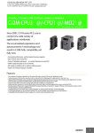
CJ2 Series
CJ2 CPU Units
CJ2H CPU Units
CJ2H-CPU6@-EIP
CJ2H-CPU6@
CJ2M CPU Units
NSJ Series
NSJ Controllers
CS1H-CPU@@H
NSJ5-SQ@@(B)-G5D
CS1G-CPU@@H
NSJ8-TV@@(B)-G5D
NSJ10-TV@@(B)-G5D
NSJ12-TS@@(B)-G5D
NSJ Controllers
NSJ5-TQ@@(B)-M3D
NSJ5-SQ@@(B)-M3D
CJ1-H CPU Units
CS1-H CPU Units
NSJ5-TQ@@(B)-G5D
CJ2M-CPU3@
CJ2M-CPU1@
Pulse I/O Module for
CJ2M CPU Units
CS Series
NSJ8-TV@@(B)-M3D
CS1D CPU Units
CS1D CPU Units
for Duplex Systems
CS1D-CPU@@H
CS1D CPU Units
for Simplex Systems
CS1D-CPU@@S
CS1D Process-control CPU Units
CJ1H-CPU@@H-R
CS1D-CPU@@P
CJ1H-CPU@@H
CJ1G-CPU@@H
CJ1G -CPU@@P
(Loop CPU Units)
CS1 CPU Units
CS1H-CPU@@(-V)
CJ1M CPU Units
CS1G-CPU@@(-V)
CJ1M-CPU@@
CS-series Basic I/O Units
CJ1 CPU Units
CS-series Special I/O Units
CJ1G-CPU@@
CJ-series Basic I/O Units
NSJ-series Expansion Units
CS-series CPU Bus Units
CS-series Power Supply Units
CJ-series Special I/O Units
Note: A special Power Supply Unit must
be used for CS1D CPU Units.
CJ-series CPU Bus Units
CJ-series Power Supply Units
CJ2 CPU Unit Software User’s Manual
1
CJ2 CPU Unit Manuals
Information on the CJ2 CPU Units is provided in the following manuals. Refer to the appropriate manual
for the information that is required.
This Manual
Mounting
and Setting
1 Hardware
CJ-series CJ2 CPU Unit
Hardware User’s Manual
(Cat. No. W472)
CJ-series CJ2 CPU Unit
Software User’s Manual
(Cat. No. W473)
CS/CJ/NSJ Series
Instructions Reference
Manual (Cat. No. W474)
• Unit part names and
specifications
• Basic system
configuration
• Unit mounting
procedure
• Setting procedure for
DIP switch and rotary
switches on the front of
the CPU Unit
2 Wiring
• Specifications and wiring
of Pulse I/O Modules
• Available pulse I/O
functions and allocations
For details on built-in
EtherNet/IP port, refer to
the EtherNet/IP Unit
Operation Manual (W465)
• Wiring the Power
Supply Unit
Connecting • Wring Basic I/O Units
and external I/O
Online to
devices
• Pulse I/O Module
specifications
• Wiring methods between
Pulse I/O Modules and
external I/O devices
3 the PLC
CX-Programmer Support
Software Connecting
Cables
Software
4 Setup
Procedures for connecting
the CX-Programmer
Support Software
Software setting methods for the
CPU Unit (including I/O memory
allocation, PLC Setup settings,
Special I/O Unit parameters,
CPU Bus Unit parameters, and
routing tables.)
Creating the
5 Program
For details on built-in EtherNet/IP
port, refer to the EtherNet/IP Unit
Operation Manual (W465).
• Program types and basic
information
• CPU Unit operation
• Internal memory
• Data management using
file memory in the CPU
Unit
• Built-in CPU functions
• Settings
Checking
and
Debugging
6 Operation
Maintenance
and
7 Troubleshooting
CJ2M CPU Unit Pulse
I/O Module User's
Manual (Cat. No. W486)
Detailed information
on programming
instructions
Software setting
procedures for Pulse I/O
Modules (I/O memory
allocations and PLC
Setup settings)
Pulse I/O functions
• Checking I/O wiring, setting the
Auxiliary Area settings, and
performing trial operation
• Monitoring and debugging with
the CX-Programmer
Error codes and
remedies if a problem
occurs
2
CJ2 CPU Unit Software User’s Manual
Manual Configuration
The CJ2 CPU manuals are organized in the sections listed in the following tables. Refer to the appropriate section in the manuals as required.
Hardware User’s Manual (Cat. No. W472)
Section
Section 1 Overview
Content
This section gives an overview of the CJ2 CPU Units and describes the features and
specifications.
Section 2 Basic System Configuration and Devices
This section describes the system configuration for the CJ2 CPU Unit.
Section 3 Nomenclature and
Functions
This section describes the part names and functions of the CPU Unit and Configuration
Units.
Section 4 Support Software
This section describes the types of Support Software to use to perform programming and
debugging and how to connect the PLC to the Support Software.
Section 5 Installation
This section describes the installation locations and how to wire CPU Units and Configuration Units.
Section 6 Troubleshooting
This section describes how to check the status for errors that occur during system operation and the remedies for those errors.
Section 7 Inspection and Maintenance
This section describes periodic inspection, the service life of the Battery and Power Supply Unit, and how to replace the Battery.
Section 8 Backup Operations
This section describes the procedure to back up PLC data.
Appendices
The appendices provide Unit dimensions, details on fatal and non-fatal errors, information on connecting to serial ports on the CPU Unit, the procedure for installing the USB
driver on a computer, and information on load short-circuit protection and line disconnection detection.
Software User’s Manual (Cat. No. W473) (This Manual)
Section
Section 1 Overview
Content
This section gives an overview of the CJ2 CPU Units and describes the features and
specifications.
Section 2 Internal Memory in the
CPU Unit
This section describes the types of memory in the CPU Unit and the data that is stored.
Section 3 CPU Unit Operation
This section describes the internal operation of the CPU Unit.
Section 4 CPU Unit Initialization
This section describes the initial setup of the CPU Unit.
Section 5 Understanding Programming
This section describes program types and programming details, such as symbols and
programming instructions.
Section 6 I/O Memory Areas
This section describes the I/O memory areas in the CPU Unit.
Section 7 File Operations
This section describes the files that can be stored in the CPU Unit, the storage destination for those files, and file operations.
Section 8 I/O Allocations and
Unit Settings
This section describes the I/O allocations used to exchange data between the CPU Unit
and other Units.
Section 9 PLC Setup
This section describes details on the PLC Setup settings, which are used to perform
basic settings for the CPU Unit.
Section 10 CPU Unit Functions
This section describes functions that are built into the CPU Unit.
Section 11 Programming Devices
and Communications
This section describes the procedure for connecting the CJ2 CPU Unit to the CX-Programmer or other Support Software and to other devices.
Section 12 CPU Unit Cycle Time
This section describes how to monitor and calculate the cycle time.
Appendices
The appendices provide information on programming instructions, execution times, number of steps, Auxiliary Area words and bits, a memory map of the continuous PLC memory addresses, I/O memory operation when power is interrupted, and a comparison of
CJ-series and CS-series PLCs.
CJ2 CPU Unit Software User’s Manual
3
Instructions Reference Manual (Cat. No. W474)
Section
Content
Section 1 Basic Understanding
of Instructions
This section provides basic information on designing ladder programs for a CS/CJ/NSJseries CPU Unit.
Section 2 Summary of Instructions
This section provides a summary of instructions used with a CS/CJ/NSJ-series CPU
Unit.
Section 3 Instructions
This section describes the functions, operands and sample programs of the instructions
that are supported by a CS/CJ/NSJ-series CPU Unit.
Section 4 Instruction Execution
Times and Number of Steps
This section provides the instruction execution times for each CS/CJ/NSJ-series CPU
Unit instruction.
Appendices
The appendices provide a list of instructions by function code and by mnemonic and an
ASCII table for the CS/CJ/NSJ-series CPU Units.
Pulse I/O Module User's Manual (Cat. No. W486)
Section
4
Content
Section 1 Overview
This section gives an overview of the Pulse I/O Modules and the pulse I/O functions of
the CJ2M.
Section 2 I/O Application Procedures and Function Allocations
This section lists the pulse functions of the CJ2M CPU Units and describes the overall
application flow and the allocation of the functions.
Section 3 I/O Specifications and
Wiring for Pulse I/O Modules
This section provides the specifications and describes the wiring of the Pulse I/O Module.
Section 4 General-purpose I/O
This section describes the general-purpose I/O.
Section 5 Quick-response Inputs
This section describes the quick-response function that can be used to input signals that
are shorter than the cycle time.
Section 6 Interrupts
This section describes the interrupt input function.
Section 7 High-speed Counters
This section describes the high-speed counter inputs and high-speed counter interrupts.
Section 8 Pulse Outputs
This section describes positioning functions, such as trapezoidal control, S-curve control,
jogging, and origin search functions.
Section 9 PWM Outputs
This section describes the variable-duty-factor (PWM) outputs.
Appendices
The appendices provide a table of flag changes for pulse outputs, a comparison table
with other models, and a performance table.
CJ2 CPU Unit Software User’s Manual
Manual Structure
Page Structure
The following page structure is used in this manual.
Level 1 heading
Level 2 heading
Level 3 heading
5 Installation
Level 2 heading
Level 3 heading
5-2
5-2-1
Installation
Gives the current
headings.
Connecting PLC Components
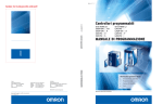
The Units that make up a CJ-series PLC can be connected simply by pressing the Units together and
locking the sliders by moving them toward the back of the Units. The End Cover is connected in the
same way to the Unit on the far right side of the PLC.
A step
in a procedure
1. Join the Units so that the connectors fit exactly.
Hook
Hook holes
Connector
5-2 Installation
5
toward the back of the Units as shown below until they click into place.
Move the sliders toward the back
until they lock into place.
Lock
Release
Slider
Special Information
(See below.)
Manual name
5-2-1 Connecting PLC Components
2. The yellow sliders at the top and bottom of each Unit lock the Units together. Move the sliders
Page tab
Gives the number
of the section.
Precautions for Correct Use
If the locking tabs are not secured properly, the connectors may become loose and not function
properly. Be sure to slide the locking tabs until they are securely in place.
CJ2 CPU Unit Hardware User’s Manual
5-13
This illustration is provided only as a sample and may not literally appear in this manual.
Special Information
Special information in this manual is classified as follows:
Precautions for Safe Use
Precautions on what to do and what not to do to ensure using the product safely.
Precautions for Correct Use
Precautions on what to do and what not to do to ensure proper operation and performance.
Additional Information
Additional information to increase understanding or make operation easier.
CJ2 CPU Unit Software User’s Manual
5
6
CJ2 CPU Unit Software User’s Manual
Sections in this Manual
1
2
Overview
Internal Memory
in the CPU Unit
10
11
CPU Unit
Functions
1
10
2
11
3
12
4
A
Programming Devices
and Communications
3
CPU Unit
Operation
12
CPU Unit
Cycle Time
5
4
CPU Unit
Initialization
A
Appendices
6
5
Understanding Programming
6
7
8
I/O Memory Areas
9
7
File Operations
8
I/O Allocations and Unit Settings
9
PLC Setup
CJ2 CPU Unit Software User’s Manual
7
8
CJ2 CPU Unit Software User’s Manual
CONTENTS
Introduction............................................................................................................... 1
CJ2 CPU Unit Manuals ............................................................................................. 2
Manual Structure ...................................................................................................... 5
Sections in this Manual............................................................................................ 7
Safety Precautions ................................................................................................. 21
Application Precautions......................................................................................... 25
Operating Environment Precautions .................................................................... 30
Regulations and Standards ................................................................................... 31
Unit Versions of CJ2 CPU Units ............................................................................ 33
Related Manuals ..................................................................................................... 39
Section 1
1-1
Overview
Overview of CJ2 CPU Units .................................................................................................... 1-2
1-1-1
1-1-2
1-2
Basic Operating Procedure .................................................................................................. 1-12
Section 2
2-1
Internal Memory in the CPU Unit
Overview................................................................................................................................... 2-2
2-1-1
2-1-2
2-1-3
Section 3
3-1
Memory Configuration ................................................................................................................ 2-2
Memory Areas and Stored Data ................................................................................................. 2-3
Transferring Data from a Programming Device to the CPU Unit................................................. 2-4
CPU Unit Operation
CPU Unit Internal Operation ................................................................................................... 3-2
3-1-1
3-1-2
3-1-3
3-2
Overview..................................................................................................................................... 1-2
CJ2 CPU Unit Features .............................................................................................................. 1-4
Overview..................................................................................................................................... 3-2
Cycle Time.................................................................................................................................. 3-4
Processing at Power Interruptions .............................................................................................. 3-7
CPU Unit Operating Modes..................................................................................................... 3-8
3-2-1
3-2-2
3-2-3
3-2-4
Operating Modes ........................................................................................................................ 3-8
Checking the Operating Mode .................................................................................................... 3-9
Changing the Operating Mode.................................................................................................. 3-10
Operating Mode Details ............................................................................................................ 3-14
CJ2 CPU Unit Software User’s Manual
9
Section 4
4-1
CPU Unit Initialization
Overview of CPU Unit Initialization ........................................................................................ 4-2
4-1-1
4-2
4-3
PLC Setup ................................................................................................................................ 4-8
Creating I/O Tables .................................................................................................................. 4-9
4-3-1
4-3-2
4-3-3
4-4
Section 5
Programming ........................................................................................................................... 5-3
Overview ................................................................................................................................... 5-47
Types of Symbols ...................................................................................................................... 5-48
Global Symbols ......................................................................................................................... 5-50
Local Symbols........................................................................................................................... 5-50
Network Symbols (CJ2H-CPU6@-EIP and CJ2M-CPU3@ Only) ............................................. 5-51
Variables in Function Blocks ..................................................................................................... 5-55
Symbol Data Types ................................................................................................................... 5-56
Automatic Address Allocation to Symbols................................................................................. 5-61
Instructions ............................................................................................................................ 5-62
5-6-1
5-6-2
5-6-3
5-6-4
10
Function Blocks......................................................................................................................... 5-42
Features of Function Blocks...................................................................................................... 5-43
Function Block Specifications ................................................................................................... 5-44
Symbols.................................................................................................................................. 5-47
5-5-1
5-5-2
5-5-3
5-5-4
5-5-5
5-5-6
5-5-7
5-5-8
5-6
Overview of Sections ................................................................................................................ 5-40
Function Blocks..................................................................................................................... 5-42
5-4-1
5-4-2
5-4-3
5-5
Overview of Tasks ..................................................................................................................... 5-11
Cyclic Tasks .............................................................................................................................. 5-14
Interrupt Tasks .......................................................................................................................... 5-20
Designing Tasks ........................................................................................................................ 5-30
Sections.................................................................................................................................. 5-40
5-3-1
5-4
Programming Overview............................................................................................................... 5-3
Basic Ladder Diagram Concepts ................................................................................................ 5-6
ST Language............................................................................................................................... 5-8
SFC Overview ............................................................................................................................. 5-9
Tasks....................................................................................................................................... 5-11
5-2-1
5-2-2
5-2-3
5-2-4
5-3
CPU Bus Unit Setup Area ......................................................................................................... 4-16
Setting Procedure ..................................................................................................................... 4-16
Understanding Programming
5-1-1
5-1-2
5-1-3
5-1-4
5-2
Setting Allocated DM Area Words for Special I/O Units and CPU Bus Units............................ 4-15
Setting Procedure ..................................................................................................................... 4-15
CPU Bus Unit Setup Area ..................................................................................................... 4-16
4-6-1
4-6-2
5-1
Routing Tables .......................................................................................................................... 4-11
Cases in Which Routing Tables Are Required .......................................................................... 4-13
Setting and Transferring Routing Tables ................................................................................... 4-14
Setting Allocated DM Area Words for Special I/O Units and CPU Bus Units ................... 4-15
4-5-1
4-5-2
4-6
I/O Tables .................................................................................................................................... 4-9
Automatic Allocation.................................................................................................................. 4-10
Manual Allocation...................................................................................................................... 4-10
Setting Routing Tables.......................................................................................................... 4-11
4-4-1
4-4-2
4-4-3
4-5
CPU Unit Initial Settings.............................................................................................................. 4-2
Basic Understanding of Instructions ......................................................................................... 5-62
Specifying Operands................................................................................................................. 5-69
Data Formats ............................................................................................................................ 5-77
I/O Refresh Timing .................................................................................................................... 5-81
CJ2 CPU Unit Software User’s Manual
5-7
Index Registers ...................................................................................................................... 5-86
5-7-1
5-7-2
5-7-3
5-7-4
5-7-5
5-8
Specifying Address Offsets.................................................................................................. 5-95
5-8-1
5-8-2
5-9
What Are Index Registers?....................................................................................................... 5-86
Using Index Registers............................................................................................................... 5-86
Processing Related to Index Registers..................................................................................... 5-91
Monitoring Index Registers ....................................................................................................... 5-92
Sharing Index and Data Registers between Tasks ................................................................... 5-93
Overview................................................................................................................................... 5-95
Examples of Address Offset Application................................................................................... 5-97
Checking Programs............................................................................................................... 5-98
5-9-1
5-9-2
5-9-3
5-9-4
Errors during CX-Programmer Input......................................................................................... 5-98
Program Checks with the CX-Programmer............................................................................... 5-98
Debugging with the Simulator................................................................................................... 5-99
Program Execution Check ...................................................................................................... 5-102
5-10 Precautions .......................................................................................................................... 5-105
5-10-1
5-10-2
Section 6
6-1
I/O Memory Areas
I/O Memory Areas .................................................................................................................... 6-2
6-1-1
6-1-2
6-1-3
6-2
Condition Flags....................................................................................................................... 5-105
Special Program Sections ...................................................................................................... 5-110
I/O Memory Area Overview ........................................................................................................ 6-2
I/O Memory Area Structure......................................................................................................... 6-4
Holding I/O Memory Values........................................................................................................ 6-6
I/O Area..................................................................................................................................... 6-8
6-2-1
6-2-2
Input Bits..................................................................................................................................... 6-8
Output Bits ................................................................................................................................ 6-10
6-3
Data Link Area ....................................................................................................................... 6-13
6-4
Synchronous Data Refresh Area.......................................................................................... 6-14
6-5
CPU Bus Unit Area ................................................................................................................ 6-15
6-6
Special I/O Unit Area ............................................................................................................. 6-16
6-7
Pulse I/O Area ........................................................................................................................ 6-17
6-8
Serial PLC Link Area ............................................................................................................. 6-18
6-9
DeviceNet Area ...................................................................................................................... 6-19
6-10 Work Area ............................................................................................................................... 6-20
6-11 Holding Area .......................................................................................................................... 6-21
6-12 Auxiliary Area ........................................................................................................................ 6-23
6-13 Temporary Relay Area........................................................................................................... 6-24
6-14 Data Memory Area ................................................................................................................. 6-25
6-15 Extended Data Memory Area................................................................................................ 6-28
6-16 Timer Areas............................................................................................................................ 6-32
6-17 Counter Areas........................................................................................................................ 6-34
6-18 Task Flags .............................................................................................................................. 6-35
6-19 Index Registers ...................................................................................................................... 6-36
6-20 Data Registers ....................................................................................................................... 6-41
6-21 Condition Flags ..................................................................................................................... 6-43
6-22 Clock Pulses .......................................................................................................................... 6-45
CJ2 CPU Unit Software User’s Manual
11
Section 7
7-1
File Operations
File Memory.............................................................................................................................. 7-2
7-1-1
7-1-2
7-1-3
7-2
Types of Files Stored in File Memory .................................................................................... 7-7
7-2-1
7-2-2
7-3
Section 8
Types of File Memory Operations ............................................................................................. 7-11
File Memory Operating Procedures and File Memory Files...................................................... 7-13
Restrictions on File Use ............................................................................................................ 7-19
File Sizes................................................................................................................................... 7-20
Relation between Support Software and File Memory Files ..................................................... 7-21
I/O Allocations and Unit Settings
I/O Allocations ......................................................................................................................... 8-2
8-1-1
8-1-2
8-1-3
8-1-4
8-2
File Types .................................................................................................................................... 7-7
Creating and Saving Files for File Memory ............................................................................... 7-10
File Memory Operations........................................................................................................ 7-11
7-3-1
7-3-2
7-3-3
7-3-4
7-3-5
8-1
Types of File Memory.................................................................................................................. 7-2
Initializing File Memory ............................................................................................................... 7-3
Memory Card Precautions .......................................................................................................... 7-5
I/O Allocations ............................................................................................................................. 8-2
Automatic Allocation.................................................................................................................... 8-5
Manual Allocation........................................................................................................................ 8-9
I/O Table Errors and Precautions .............................................................................................. 8-17
Setting CPU Bus Units and Special I/O Units ..................................................................... 8-20
8-2-1
8-2-2
Section 9
Setting Parameters ................................................................................................................... 8-20
Data Exchange.......................................................................................................................... 8-24
PLC Setup
9-1
Overview of the PLC Setup..................................................................................................... 9-2
9-2
PLC Setup Settings ................................................................................................................. 9-4
9-3
PLC Setup Settings ................................................................................................................. 9-5
9-3-1
9-3-2
9-3-3
9-3-4
9-3-5
9-3-6
9-3-7
9-3-8
9-3-9
Section 10
Startup Operation Settings.......................................................................................................... 9-5
CPU Unit Settings ....................................................................................................................... 9-8
Timings/Synchronous Settings.................................................................................................. 9-14
Special I/O Unit Cyclic Refreshing ............................................................................................ 9-19
Basic I/O Unit Rack Response Times ....................................................................................... 9-21
Serial Port Settings ................................................................................................................... 9-23
Peripheral Service..................................................................................................................... 9-30
FINS Protection......................................................................................................................... 9-31
I/O Module................................................................................................................................. 9-32
CPU Unit Functions
10-1 Clock Functions..................................................................................................................... 10-3
10-1-1
10-1-2
10-1-3
Clock Functions......................................................................................................................... 10-3
Times Stored in Memory........................................................................................................... 10-4
Free-running Timers.................................................................................................................. 10-6
10-2 Cycle Time/High-speed Processing..................................................................................... 10-7
10-2-1
10-2-2
10-2-3
10-2-4
10-2-5
10-2-6
12
Minimum Cycle Time................................................................................................................. 10-7
Maximum Cycle Time................................................................................................................ 10-8
Monitoring the Cycle Time ........................................................................................................ 10-9
High-speed Inputs ..................................................................................................................... 10-9
Background Execution ............................................................................................................ 10-10
High-speed Interrupt Function ................................................................................................ 10-19
CJ2 CPU Unit Software User’s Manual
10-3 Startup Settings and Maintenance..................................................................................... 10-22
10-3-1
10-3-2
10-3-3
10-3-4
10-3-5
Holding Settings for Operating Mode Changes and at Startup............................................... 10-22
Power OFF Detection Delay Setting ....................................................................................... 10-24
Disabling Power OFF Interrupts.............................................................................................. 10-25
RUN Output ............................................................................................................................ 10-26
Automatic Transfer at Startup ................................................................................................. 10-27
10-4 Unit Management Functions .............................................................................................. 10-35
10-4-1
10-4-2
10-4-3
Basic I/O Unit Management.................................................................................................... 10-35
CPU Bus Unit Flags/Bits......................................................................................................... 10-37
Special I/O Unit Flags/Bits ...................................................................................................... 10-38
10-5 Memory Management Functions........................................................................................ 10-39
10-5-1
10-5-2
10-5-3
10-5-4
Automatic Backup ................................................................................................................... 10-39
EM File Memory Functions..................................................................................................... 10-41
Comment Memory .................................................................................................................. 10-42
Replacing the Entire Program during Operation..................................................................... 10-43
10-6 Security Functions .............................................................................................................. 10-50
10-6-1
10-6-2
10-6-3
10-6-4
10-6-5
Write-protection Using the DIP Switch ................................................................................... 10-50
Read Protection Using Passwords ......................................................................................... 10-50
Program Operation Protection Using Production Lot Numbers .............................................. 10-55
Write Protection from FINS Commands ................................................................................. 10-56
PLC Names ............................................................................................................................ 10-60
10-7 Debugging ............................................................................................................................ 10-63
10-7-1
10-7-2
10-7-3
10-7-4
10-7-5
10-7-6
10-7-7
10-7-8
10-7-9
10-7-10
Forced Set/Reset.................................................................................................................... 10-63
Test Input ................................................................................................................................ 10-64
Differential Monitoring............................................................................................................. 10-64
Online Editing ......................................................................................................................... 10-65
Turning OFF Outputs .............................................................................................................. 10-67
Tracing Data............................................................................................................................ 10-68
Storing the Stop Position at Errors ......................................................................................... 10-76
Failure Alarm Instructions ....................................................................................................... 10-77
Simulating System Errors ....................................................................................................... 10-78
Failure Point Detection............................................................................................................ 10-79
10-8 Synchronous Unit Operation.............................................................................................. 10-81
10-8-1
10-8-2
10-8-3
10-8-4
10-8-5
10-8-6
10-8-7
10-8-8
10-8-9
Section 11
Overview................................................................................................................................. 10-81
Details on Synchronous Unit Operation.................................................................................. 10-85
Synchronous Unit Operation Specifications ........................................................................... 10-89
Synchronous Data Refresh..................................................................................................... 10-90
Restrictions in Using Synchronous Unit Operation................................................................. 10-94
Application Procedure............................................................................................................. 10-96
PLC Setup .............................................................................................................................. 10-97
Writing the Synchronous Interrupt Task.................................................................................. 10-99
Adjusting and Troubleshooting Synchronous Unit Operation ............................................... 10-100
Programming Devices and Communications
11-1 Accessing a PLC from the CX-Programmer........................................................................ 11-2
11-1-1
11-1-2
11-1-3
11-1-4
Overview................................................................................................................................... 11-2
System Configurations for Accessible PLCs............................................................................. 11-4
Accessing a PLC from the CX-Programmer ............................................................................. 11-8
Automatic Online Connection ................................................................................................. 11-11
11-2 Serial Communications....................................................................................................... 11-15
11-2-1
Overview of Serial Communications....................................................................................... 11-15
11-3 Communications Networks ................................................................................................ 11-29
CJ2 CPU Unit Software User’s Manual
13
Section 12
CPU Unit Cycle Time
12-1 Monitoring the Cycle Time.................................................................................................... 12-2
12-1-1
Monitoring the Cycle Time ........................................................................................................ 12-2
12-2 Computing the Cycle Time ................................................................................................... 12-4
12-2-1
12-2-2
12-2-3
12-2-4
12-2-5
12-2-6
12-2-7
12-2-8
CPU Unit Operation Flowchart.................................................................................................. 12-4
Cycle Time Overview ................................................................................................................ 12-5
I/O Unit Refresh Times for Individual Units ............................................................................... 12-7
Cycle Time Calculation Example ............................................................................................ 12-11
Online Editing Cycle Time Extension ...................................................................................... 12-13
I/O Response Time ................................................................................................................. 12-13
Response Time for Input Interrupts......................................................................................... 12-14
Response Performance of Serial PLC Links ........................................................................... 12-15
Appendices
A-1 Instruction Functions ..............................................................................................................A-3
A-1-1
A-1-2
A-1-3
A-1-4
A-1-5
A-1-6
A-1-7
A-1-8
A-1-9
A-1-10
A-1-11
A-1-12
A-1-13
A-1-14
A-1-15
A-1-16
A-1-17
A-1-18
A-1-19
A-1-20
A-1-21
A-1-22
A-1-23
A-1-24
A-1-25
A-1-26
A-1-27
A-1-28
A-1-29
A-1-30
A-1-31
A-1-32
A-1-33
A-1-34
A-1-35
14
Sequence Input Instructions .......................................................................................................A-3
Sequence Output Instructions.....................................................................................................A-5
Sequence Control Instructions ....................................................................................................A-6
Timer and Counter Instructions.................................................................................................A-10
Comparison Instructions ...........................................................................................................A-14
Data Movement Instructions .....................................................................................................A-18
Data Shift Instructions...............................................................................................................A-20
Increment/Decrement Instructions ............................................................................................A-24
Symbol Math Instructions..........................................................................................................A-24
Conversion Instructions.............................................................................................................A-29
Logic Instructions ......................................................................................................................A-35
Special Math Instructions ..........................................................................................................A-37
Floating-point Math Instructions................................................................................................A-38
Double-precision Floating-point Instructions .............................................................................A-42
Table Data Processing Instructions...........................................................................................A-45
Tracking Instructions .................................................................................................................A-49
Data Control Instructions ..........................................................................................................A-50
Subroutine Instructions .............................................................................................................A-54
Interrupt Control Instructions.....................................................................................................A-55
High-speed Counter/Pulse Output Instructions.........................................................................A-56
Step Instructions .......................................................................................................................A-58
Basic I/O Unit Instructions.........................................................................................................A-58
Serial Communications Instructions..........................................................................................A-61
Network Instructions .................................................................................................................A-63
File Memory Instructions...........................................................................................................A-65
Display Instructions ...................................................................................................................A-66
Clock Instructions......................................................................................................................A-67
Debugging Instructions .............................................................................................................A-68
Failure Diagnosis Instructions ...................................................................................................A-68
Other Instructions......................................................................................................................A-69
Block Programming Instructions ...............................................................................................A-70
Text String Processing Instructions ...........................................................................................A-74
Task Control Instructions...........................................................................................................A-77
Model Conversion Instructions..................................................................................................A-77
Special Function Block Instructions ..........................................................................................A-78
CJ2 CPU Unit Software User’s Manual
A-2 Instruction Execution Times and Number of Steps ...........................................................A-80
A-2-1
A-2-2
A-2-3
A-2-4
A-2-5
A-2-6
A-2-7
A-2-8
A-2-9
A-2-10
A-2-11
A-2-12
A-2-13
A-2-14
A-2-15
A-2-16
A-2-17
A-2-18
A-2-19
A-2-20
A-2-21
A-2-22
A-2-23
A-2-24
A-2-25
A-2-26
A-2-27
A-2-28
A-2-29
A-2-30
A-2-31
A-2-32
A-2-33
A-2-34
A-2-35
A-2-36
A-2-37
Sequence Input Instructions ..................................................................................................... A-81
Sequence Output Instructions .................................................................................................. A-82
Sequence Control Instructions ................................................................................................. A-82
Timer and Counter Instructions ................................................................................................ A-83
Comparison Instructions........................................................................................................... A-84
Data Movement Instructions ..................................................................................................... A-86
Data Shift Instructions .............................................................................................................. A-86
Increment/Decrement Instructions............................................................................................ A-87
Symbol Math Instructions ......................................................................................................... A-88
Conversion Instructions ............................................................................................................ A-90
Logic Instructions...................................................................................................................... A-92
Special Math Instructions ......................................................................................................... A-92
Floating-point Math Instructions ............................................................................................... A-93
Double-precision Floating-point Instructions............................................................................. A-94
Table Data Processing Instructions .......................................................................................... A-95
Tracking Instructions ................................................................................................................. A-97
Data Control Instructions .......................................................................................................... A-97
Subroutine Instructions............................................................................................................. A-98
Interrupt Control Instructions .................................................................................................... A-99
High-speed Counter/Pulse Output Instructions ........................................................................ A-99
Step Instructions..................................................................................................................... A-102
Basic I/O Unit Instructions ...................................................................................................... A-102
Serial Communications Instructions ....................................................................................... A-103
Network Instructions ............................................................................................................... A-104
File Memory Instructions ........................................................................................................ A-104
Display Instructions................................................................................................................. A-105
Clock Instructions ................................................................................................................... A-105
Debugging Instructions ........................................................................................................... A-105
Failure Diagnosis Instructions................................................................................................. A-105
Other Instructions ................................................................................................................... A-106
Block Programming Instructions ............................................................................................. A-106
Text String Processing Instructions......................................................................................... A-108
Task Control Instructions ........................................................................................................ A-109
Model Conversion Instructions ............................................................................................... A-109
Special Function Block Instructions ........................................................................................ A-110
SFC Instructions ..................................................................................................................... A-110
Function Block Instance Execution Time ................................................................................ A-110
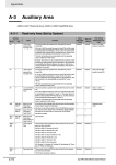
A-3 Auxiliary Area ......................................................................................................................A-112
A-3-1
A-3-2
A-3-3
Read-only Area (Set by System) ............................................................................................ A-112
Read/Write Area (Set by User) ............................................................................................... A-151
Details on Auxiliary Area Operation........................................................................................ A-162
A-4 Memory Map of PLC Memory Addresses..........................................................................A-165
A-4-1
A-4-2
PLC Memory Addresses......................................................................................................... A-165
Memory Map........................................................................................................................... A-166
A-5 Operation for Power Interruptions .....................................................................................A-167
A-5-1
A-5-2
Power OFF Operation............................................................................................................. A-167
Instruction Execution for Power Interruptions ......................................................................... A-169
A-6 EtherNet/IP Connections from Windows XP (SP2 or Higher), Windows Vista, or Windows 7
A-171
A-6-1
Changing Windows Firewall Settings...................................................................................... A-171
A-7 PLC Comparison Charts: CJ-series and CS-series PLCs ...............................................A-174
A-8 Functions Supported for Unit Versions.............................................................................A-178
A-8-1
A-8-2
CJ2H CPU Unit....................................................................................................................... A-178
CJ2M CPU Unit ...................................................................................................................... A-179
Index ................................................................................................................ Index-1
Revision History ....................................................................................... Revision-1
CJ2 CPU Unit Software User’s Manual
15
16
CJ2 CPU Unit Software User’s Manual
Read and Understand this Manual
Please read and understand this manual before using the product. Please consult your OMRON representative
if you have any questions or comments.
Warranty and Limitations of Liability
WARRANTY
OMRON's exclusive warranty is that the products are free from defects in materials and workmanship for a
period of one year (or other period if specified) from date of sale by OMRON.
OMRON MAKES NO WARRANTY OR REPRESENTATION, EXPRESS OR IMPLIED, REGARDING NONINFRINGEMENT, MERCHANTABILITY, OR FITNESS FOR PARTICULAR PURPOSE OF THE
PRODUCTS. ANY BUYER OR USER ACKNOWLEDGES THAT THE BUYER OR USER ALONE HAS
DETERMINED THAT THE PRODUCTS WILL SUITABLY MEET THE REQUIREMENTS OF THEIR
INTENDED USE. OMRON DISCLAIMS ALL OTHER WARRANTIES, EXPRESS OR IMPLIED.
LIMITATIONS OF LIABILITY
OMRON SHALL NOT BE RESPONSIBLE FOR SPECIAL, INDIRECT, OR CONSEQUENTIAL DAMAGES,
LOSS OF PROFITS OR COMMERCIAL LOSS IN ANY WAY CONNECTED WITH THE PRODUCTS,
WHETHER SUCH CLAIM IS BASED ON CONTRACT, WARRANTY, NEGLIGENCE, OR STRICT
LIABILITY.
In no event shall the responsibility of OMRON for any act exceed the individual price of the product on which
liability is asserted.
IN NO EVENT SHALL OMRON BE RESPONSIBLE FOR WARRANTY, REPAIR, OR OTHER CLAIMS
REGARDING THE PRODUCTS UNLESS OMRON'S ANALYSIS CONFIRMS THAT THE PRODUCTS
WERE PROPERLY HANDLED, STORED, INSTALLED, AND MAINTAINED AND NOT SUBJECT TO
CONTAMINATION, ABUSE, MISUSE, OR INAPPROPRIATE MODIFICATION OR REPAIR.
CJ2 CPU Unit Software User’s Manual
17
Application Considerations
SUITABILITY FOR USE
OMRON shall not be responsible for conformity with any standards, codes, or regulations that apply to the
combination of products in the customer's application or use of the products.
At the customer's request, OMRON will provide applicable third party certification documents identifying
ratings and limitations of use that apply to the products. This information by itself is not sufficient for a
complete determination of the suitability of the products in combination with the end product, machine,
system, or other application or use.
The following are some examples of applications for which particular attention must be given. This is not
intended to be an exhaustive list of all possible uses of the products, nor is it intended to imply that the uses
listed may be suitable for the products:
• Outdoor use, uses involving potential chemical contamination or electrical interference, or conditions or
uses not described in this manual.
• Nuclear energy control systems, combustion systems, railroad systems, aviation systems, medical
equipment, amusement machines, vehicles, safety equipment, and installations subject to separate
industry or government regulations.
• Systems, machines, and equipment that could present a risk to life or property.
Please know and observe all prohibitions of use applicable to the products.
NEVER USE THE PRODUCTS FOR AN APPLICATION INVOLVING SERIOUS RISK TO LIFE OR
PROPERTY WITHOUT ENSURING THAT THE SYSTEM AS A WHOLE HAS BEEN DESIGNED TO
ADDRESS THE RISKS, AND THAT THE OMRON PRODUCTS ARE PROPERLY RATED AND
INSTALLED FOR THE INTENDED USE WITHIN THE OVERALL EQUIPMENT OR SYSTEM.
PROGRAMMABLE PRODUCTS
OMRON shall not be responsible for the user's programming of a programmable product, or any
consequence thereof.
18
CJ2 CPU Unit Software User’s Manual
Disclaimers
CHANGE IN SPECIFICATIONS
Product specifications and accessories may be changed at any time based on improvements and other
reasons.
It is our practice to change model numbers when published ratings or features are changed, or when
significant construction changes are made. However, some specifications of the products may be changed
without any notice. When in doubt, special model numbers may be assigned to fix or establish key
specifications for your application on your request. Please consult with your OMRON representative at any
time to confirm actual specifications of purchased products.
DIMENSIONS AND WEIGHTS
Dimensions and weights are nominal and are not to be used for manufacturing purposes, even when
tolerances are shown.
PERFORMANCE DATA
Performance data given in this manual is provided as a guide for the user in determining suitability and does
not constitute a warranty. It may represent the result of OMRON's test conditions, and the users must
correlate it to actual application requirements. Actual performance is subject to the OMRON Warranty and
Limitations of Liability.
ERRORS AND OMISSIONS
The information in this manual has been carefully checked and is believed to be accurate; however, no
responsibility is assumed for clerical, typographical, or proofreading errors, or omissions.
CJ2 CPU Unit Software User’s Manual
19
20
CJ2 CPU Unit Software User’s Manual
Safety Precautions
Definition of Precautionary Information
The following notation is used in this manual to provide precautions required to ensure safe usage of a
CJ-series PLC. The safety precautions that are provided are extremely important to safety. Always read
and heed the information provided in all safety precautions.
WARNING
Caution
Indicates a potentially hazardous situation which, if not avoided,
could result in death or serious injury. Additionally, there may be
severe property damage.
Indicates a potentially hazardous situation which, if not avoided,
may result in minor or moderate injury, or property damage.
Precautions for Safe Use
Indicates precautions on what to do and what not to do to ensure using the product safely.
Precautions for Correct Use
Indicates precautions on what to do and what not to do to ensure proper operation and performance.
CJ2 CPU Unit Software User’s Manual
21
Symbols
The triangle symbol indicates precautions (including warnings).
The specific operation is shown in the triangle and explained in
text. This example indicates a precaution for electric shock.
The circle and slash symbol indicates operations that you must
not do. The specific operation is shown in the circle and
explained in text.
The filled circle symbol indicates operations that you must do.
The specific operation is shown in the circle and explained in
text. This example shows a general precaution for something
that you must do.
The triangle symbol indicates precautions (including warnings).
The specific operation is shown in the triangle and explained in
text. This example indicates a general precaution.
The triangle symbol indicates precautions (including warnings).
The specific operation is shown in the triangle and explained in
text. This example indicates a precaution for hot surfaces.
22
CJ2 CPU Unit Software User’s Manual
WARNING
Do not attempt to take any Unit apart or touch the inside of any Unit while the
power is being supplied. Doing so may result in electric shock.
Do not touch any of the terminals or terminal blocks while the power is being
supplied. Doing so may result in electric shock.
Provide safety measures in external circuits (i.e., not in the Programmable
Controller), including the following items, to ensure safety in the system if an
abnormality occurs due to malfunction of the Programmable Controller or
another external factor affecting the operation of the Programmable Controller. “Programmable Controller” indicates the CPU Unit and all other Units and
is abbreviated “PLC” in this manual. Not doing so may result in serious accidents.
• The PLC will turn OFF all outputs when its self-diagnosis function detects
any error or when a severe failure alarm (FALS) instruction is executed.
Unexpected operation, however, may still occur for errors in the I/O control
section, errors in I/O memory, and other errors that cannot be detected by
the self-diagnosis function. As a countermeasure for all such errors, external safety measures must be provided to ensure safety in the system.
• The PLC outputs may remain ON or OFF due to deposition or burning of
the output relays or destruction of the output transistors. As a countermeasure for such problems, external safety measures must be provided to
ensure safety in the system.
• Provide measures in the computer system and programming to ensure
safety in the overall system even if communications errors or malfunctions
occur in data link communications or remote I/O communications.
Confirm safety before transferring data files stored in the file memory (Memory Card or EM file memory) to the I/O area (CIO) of the CPU Unit using a
peripheral tool. Otherwise, the devices connected to the output unit may malfunction regardless of the operation mode of the CPU Unit.
Fail-safe measures must be taken by the customer to ensure safety in the
event of incorrect, missing, or abnormal signals caused by broken signal
lines, momentary power interruptions, or other causes. Serious accidents
may result from abnormal operation if proper measures are not provided.
CJ2 CPU Unit Software User’s Manual
23
Caution
Execute online edit only after confirming that no adverse effects will be
caused by extending the cycle time. Otherwise, the input signals may not be
readable.
Confirm safety at the destination node before transferring a program, PLC
Setup, I/O tables, I/O memory contents, or parameters to another node or
changing contents of the any of these items. Transferring or changing data
can result in unexpected system operation.
The CJ2 CPU Units automatically back up the user program and parameter
data to flash memory when these are written to the CPU Unit. I/O memory
including the DM, EM, and Holding Areas), however, is not written to flash
memory.
The DM, EM, and Holding Areas can be held during power interruptions with
a battery. If there is a battery error, the contents of these areas may not be
accurate after a power interruption. If the contents of the DM, EM, and Holding Areas are used to control external outputs, prevent inappropriate outputs
from being made whenever the Battery Error Flag (A402.04) is ON.
Tighten the terminal screws on the AC Power Supply Unit to the torque specified in the operation manual. The loose screws may result in burning or malfunction.
Do not touch the Power Supply Unit when power is being supplied or immediately after the power supply is turned OFF. The Power Supply Unit will be hot
and you may be burned.
When connecting a personal computer or other peripheral device to a PLC to
which a non-insulated Power Supply Unit (CJ1W-PD022) is mounted, either
ground the 0 V side of the external power supply or do not ground the external power supply at all ground. A short-circuit will occur in the external power
supply if incorrect grounding methods are used. Never ground the 24 V side,
as shown below.
Wiring in Which the 24-V Power Supply Will Short
Non-insulated
24 V DC power supply
Peripheral
cable
0V
FG
24
Power Supply
Unit
CPU Unit
0V
Peripheral device (e.g.,
personal computer)
CJ2 CPU Unit Software User’s Manual
Application Precautions
Observe the following precautions when using a CJ-series PLC.
z Power Supply
• Always use the power supply voltages specified in the user’s manuals. An incorrect voltage may
result in malfunction or burning.
• Exceeding the capacity of the Power Supply Unit may prevent the CPU Unit or other Units from
starting.
• Take appropriate measures to ensure that the specified power with the rated voltage and frequency is supplied. Be particularly careful in places where the power supply is unstable. An incorrect power supply may result in malfunction.
• Always turn OFF the power supply to the PLC before attempting any of the following. Not turning
OFF the power supply may result in malfunction or electric shock.
• Mounting or dismounting Power Supply Units, I/O Units, CPU Units, Option Boards, Pulse I/O
Modules, or any other Units.
• Assembling the Units.
• Setting DIP switches or rotary switches.
• Connecting cables or wiring the system.
• Connecting or disconnecting the connectors.
• When cross-wiring terminals, the total current for all the terminal will flow in the wire. Make sure
that the current capacity of the wire is sufficient.
• Observe the following precautions when using a Power Supply Unit that supports the Replacement Notification Function.
• Replace the Power Supply Unit within six months if the display on the front of the Power Supply Unit alternates between 0.0 and A02, or if the alarm output automatically turns OFF.
• Keep the alarm output cable separated from power line and high-voltage lines.
• Do not apply a voltage or connect a load exceeding the specifications to the alarm output.
• When storing the Power Supply Unit for more than three months, store it at −20 to 30°C and
25% to 70% humidity to preserve the Replacement Notification Function.
• If the Power Supply Unit is not installed properly, heat buildup may cause the replacement notification signal to appear at the wrong time or may cause interior elements to deteriorate or
become damaged. Use only the standard installation method.
• Do not touch the terminals on the Power Supply Unit immediately after turning OFF the power
supply. Residual voltage may cause electrical shock.
• Observe the following precautions to prevent failure due to difference in electrical potential if the
computer is connected to the PLC.
• Before connecting a laptop computer to the PLC, disconnect the power supply plug of the
computer from the AC outlet. Residual current in the AC adaptor may cause difference in electrical potential to occur between the computer and the PLC. After you connect the computer
and PLC, supply the power again from the AC adaptor.
• If the computer has an FG terminal, make the connections so that it has the same electrical
potential as the FG (GR) terminal on the PLC.
• If the computer is grounded to a separate location, difference in electrical potential may occur
depending on the grounding conditions.
z Installation
• Do not install the PLC near sources of strong high-frequency noise.
• Before touching a Unit, be sure to first touch a grounded metallic object in order to discharge any
static build-up. Not doing so may result in malfunction or damage.
CJ2 CPU Unit Software User’s Manual
25
• Be sure that the terminal blocks, connectors, Memory Cards, Option Boards, Pulse I/O Modules,
expansion cables, and other items with locking devices are properly locked into place.
• The sliders on the tops and bottoms of the Power Supply Unit, CPU Unit, I/O Units, Special I/O
Units, CPU Bus Units, and Pulse I/O Modules must be completely locked (until they click into
place) after connecting to adjacent Units. The Unit may not operate properly if the sliders are not
locked in place. It may not be possible to achieve proper functionality if the sliders are not locked.
z Wiring
• Follow the instructions in this manual to correctly perform wiring.
• Double-check all wiring and switch settings before turning ON the power supply. Incorrect wiring
may result in burning.
• Be sure that all terminal screws, and cable connector screws are tightened to the torque specified
in the relevant manuals. Incorrect tightening torque may result in malfunction.
• Mount terminal blocks and connectors only after checking the mounting location carefully.
• Leave the label attached to the Unit when wiring. Removing the label may result in malfunction if
foreign matter enters the Unit.
• Remove the label after the completion of wiring to ensure proper heat dissipation. Leaving the
label attached may result in malfunction.
• Use crimp terminals for wiring. Do not connect bare stranded wires directly to terminals. Connection of bare stranded wires may result in burning.
• Do not apply voltages to the Input Units in excess of the rated input voltage. Excess voltages may
result in burning.
• Always connect to a ground of 100 Ω or less when installing the Units. Not connecting to a ground
of 100 Ω or less may result in electric shock.
A ground of 100 Ω or less must be installed when shorting the GR and LG terminals on the Power
Supply Unit.
• Do not apply voltages or connect loads to the Output Units in excess of the maximum switching
capacity. Excess voltage or loads may result in burning.
• Do not pull on the cables or bend the cables beyond their natural limit. Doing either of these may
break the cables.
• Do not place objects on top of the cables or other wiring lines. Doing so may break the cables.
• Do not use commercially available RS-232C personal computer cables. Always use the special
cables listed in this manual or make cables according to manual specifications. Using commercially available cables may damage the external devices or CPU Unit.
• Never connect pin 6 (5-V power supply) on the RS-232C port on the CPU Unit to any device other
than an NT-AL001 Link Adapter, CJ1W-CIF11 Converter, and Programmable Terminals (NV3WM@20L). The external device or the CPU Unit may be damaged.
z Handling
• The Power Supply Unit may possibly be damaged if the entire voltage for a dielectric strength test
is applied or shut OFF suddenly using a switch. Use a variable resistor to gradually increase and
decrease the voltage.
• Separate the line ground terminal (LG) from the functional ground terminal (GR) on the Power
Supply Unit before performing withstand voltage tests or insulation resistance tests. Not doing so
may result in burning.
• Make sure that the DIP switches and DM Area are set correctly before starting operation.
• After replacing the CPU Unit, a Special I/O Unit, or a CPU Bus Unit, make sure that the required
data for the DM Area, Holding Area, and other memory areas has been transferred to the new
Unit before restarting operation.
• Confirm that no adverse effect will occur in the system before attempting any of the following. Not
doing so may result in an unexpected operation.
• Changing the operating mode of the PLC (including the setting of the startup operating mode).
• Force-setting/force-resetting any bit in memory.
26
CJ2 CPU Unit Software User’s Manual
• Changing the present value of any word or any set value in memory.
• Do not attempt to disassemble, repair, or modify any Units. Any attempt to do so may result in malfunction, fire, or electric shock.
• Do not drop the PLC or subject abnormal vibration or shock to it.
• The life of the battery will be reduced if the PLC is left for a period of time without a battery
installed and without power supply, and then a battery is installed without turning ON the power
supply.
• Replace the battery as soon as a battery error occurs or as soon as the specified battery backup
time expires. Be sure to install a replacement battery within two years of the production date
shown on the battery's label.
• Before replacing the battery, turn ON power for at least 5 minutes before starting the replacement
procedure and complete replacing the battery within 5 minutes of turning OFF the power supply.
Memory contents may be corrupted if this precaution is not obeyed.
• If the Battery Error Flag is used in programming the application, confirm system safety even if the
system detects a battery error before you replace the battery while the power is ON.
• Do not short the battery terminals or charge, disassemble, heat, or incinerate the battery. Do not
subject the battery to strong shocks. Doing any of these may result in leakage, rupture, heat generation, or ignition of the battery. Dispose of any battery that has been dropped on the floor or otherwise subjected to excessive shock. Batteries that have been subjected to shock may leak if they
are used.
• UL standards require that only an experienced engineer can replace the battery. Make sure that
an experienced engineer is in charge of battery replacement. Follow the procedure for battery
replacement given in this manual.
• Dispose of the product and batteries according to local ordinances as they apply.
• If the I/O Hold Bit is turned ON, the outputs from the PLC will not be turned OFF and will maintain
their previous status when the PLC is switched from RUN or MONITOR mode to PROGRAM
mode. Make sure that the external loads will not produce dangerous conditions when this occurs.
(When operation stops for a fatal error, including those produced with the FALS(007) instruction,
all outputs from Output Unit will be turned OFF and only the internal output status will be maintained.)
• Unexpected operation may result if inappropriate data link tables or parameters are set. Even if
appropriate data link tables and parameters have been set, confirm that the controlled system will
not be adversely affected before starting or stopping data links.
• Write programs so that any data that is received for data link communications is used only if there
are no errors in the CPU Units that are the sources of the data. Use the CPU Unit error information in the status flags to check for errors in the source CPU Units. If there are errors in source
CPU Units, they may send incorrect data.
• All CPU Bus Units will be restarted when routing tables are transferred from a Programming
Device to the CPU Unit. Restarting these Units is required to read and enable the new routing
tables. Confirm that the system will not be adversely affected before transferring the routing
tables.
• Tag data links will stop between related nodes while tag data link parameters are being transferred during PLC operation. Confirm that the system will not be adversely affected before transferring the tag data link parameters.
• If there is interference with network communications, output status will depend on the devices that
are being used. When using devices with outputs, confirm the operation that will occur when there
is interference with communications, and implement safety measures as required.
CJ2 CPU Unit Software User’s Manual
27
• When creating an AUTOEXEC.IOM file from a Programming Device (a Programming Console or
the CX-Programmer) to automatically transfer data at startup, set the first write address to
D20000 and be sure that the size of data written does not exceed the size of the DM Area. When
the data file is read from the Memory Card at startup, data will be written in the CPU Unit starting
at D20000 even if another address was set when the AUTOEXEC.IOM file was created. Also, if
the DM Area is exceeded (which is possible when the CX-Programmer is used), the remaining
data will be written to the EM Area.
• The user program and parameter area data in the CJ2 CPU Units are backed up in the built-in
flash memory. The BKUP indicator will light on the front of the CPU Unit when the backup operation is in progress. Do not turn OFF the power supply to the CPU Unit when the BKUP indicator is
lit. The data will not be backed up if power is turned OFF.
• Check the user program and Unit parameter settings for proper execution before actually running
them on the Unit. Not checking the program and parameter settings may result in an unexpected
operation.
• When setting a Special I/O Unit or CPU Bus Unit in the I/O tables, carefully check the safety of the
devices at the connection target before restarting the Unit.
• Do not turn OFF the power supply to the PLC when reading or writing a Memory Card. Also, do
not remove the Memory Card when the BUSY indicator is lit. Doing so may make the Memory
Card unusable.
To remove a Memory Card, first press the memory card power supply switch and then wait for the
BUSY indicator to go out before removing the Memory Card.
• When restoring data, carefully check that the selected data is the correct data to be restored
before executing the restore operation. Depending on the contents of the selected data, the control system may operate unexpectedly after the data is restored.
• Some Special I/O Units and CPU Bus Units operate with parameters stored in the CPU Unit (e.g.,
words allocated in DM Area, data link tables, or Ethernet settings). Information on restrictions will
be displayed in the Information Area in the PLC Backup Tool if there are any restrictions for the
selected CPU Bus Unit or Special I/O Unit. Check the restrictions, and then be sure to select both
the CPU Unit and the CPU Bus Unit or Special I/O Unit when backing up or restoring data. The
control system may operate unexpectedly if the equipment is started with the data backed up or
restored without selecting both Units.
• Information on restrictions will be displayed in the Information Area in the PLC Backup Tool if the
data to be stored includes a Unit that has restrictions on backup. Check the information on restrictions and take the required countermeasures. The control system may operate unexpectedly
when the equipment is operated after the data is restored
• Before restoring data during PLC operation, be sure that there will be no problem if PLC operation
stops. If the PLC stops at an unexpected time, the control system may operate unexpectedly.
• Be sure to turn the PLC power supply OFF and then back ON after restoring data. If the power is
not reset, the system may not be updated with the restored data, and the control system may
operate unexpectedly.
• Data on forced status can be backed up but it cannot be restored. Perform the procedure to forceset or force-reset bits from the CX-Programmer as required before starting operation after restoring data that includes forced status. Depending on the difference in the forced status, the control
system may operate unexpectedly.
• If a symbol or memory address (only symbols are allowed for ST programming) is specified for the
suffix of an array variable in ladder or ST programming, be sure that the specified element number
does not exceed the maximum memory area range.
Specifying an element number that exceeds the maximum range of the memory area specified for
the symbol will result accessing data in a different memory area, and may result in unexpected
operation.
• If a symbol or address is specified for an offset in a ladder diagram, program so that the memory
area of the start address is not exceeded when the offset is specified indirectly using a word
address or symbol.
If an indirect specification causes the address to exceed the area of the start address, the system
will access data in other area, and unexpected operation may occur.
28
CJ2 CPU Unit Software User’s Manual
z External Circuits
• Always turn ON power to the PLC before turning ON power to the control system. If the PLC
power supply is turned ON after the control power supply, temporary errors may result in control
system signals because the output terminals on DC Output Units and other Units will momentarily
turn ON when power is turned ON to the PLC.
• Install external breakers and take other safety measures against short-circuiting in external wiring.
Insufficient safety measures against short-circuiting may result in burning.
CJ2 CPU Unit Software User’s Manual
29
Operating Environment Precautions
z Follow the instructions in this manual to correctly perform installation.
z Do not operate the control system in the following locations:
• Locations subject to direct sunlight.
• Locations subject to temperatures or humidity outside the range specified in the specifications.
• Locations subject to condensation as the result of severe changes in temperature.
• Locations subject to corrosive or flammable gases.
• Locations subject to dust (especially iron dust) or salts.
• Locations subject to exposure to water, oil, or chemicals.
• Locations subject to shock or vibration.
z Take appropriate and sufficient countermeasures when installing systems in the
following locations:
• Locations subject to static electricity or other forms of noise.
• Locations subject to strong electromagnetic fields.
• Locations subject to possible exposure to radioactivity.
• Locations close to power supplies.
30
CJ2 CPU Unit Software User’s Manual
Regulations and Standards
Conformance to EC Directives
Applicable Directives
• EMC Directives
• Low Voltage Directive
Concepts
z EMC Directives
OMRON devices that comply with EC Directives also conform to the related EMC standards so that
they can be more easily built into other devices or the overall machine. The actual products have
been checked for conformity to EMC standards (see the following note). Whether the products conform to the standards in the system used by the customer, however, must be checked by the customer.
EMC-related performance of the OMRON devices that comply with EC Directives will vary depending on the configuration, wiring, and other conditions of the equipment or control panel on which the
OMRON devices are installed.
The customer must, therefore, perform the final check to confirm that devices and the overall
machine conform to EMC standards.
* Applicable EMC (Electromagnetic Compatibility) standards are as follows:
EMS (Electromagnetic Susceptibility):
CS Series: EN 61131-2 and EN 61000-6-2
CJ Series: EN 61000-6-2
* EMI (Electromagnetic Interference):
EN 61000-6-4 (Radiated emission: 10-m regulations)
z Low Voltage Directive
Always ensure that devices operating at voltages of 50 to 1,000 VAC and 75 to 1,500 VDC meet the
required safety standards for the PLC (EN 61131-2).
z Conformance to EC Directives
The CJ-series PLCs comply with EC Directives. To ensure that the machine or device in which the
CJ-series PLC is used complies with EC Directives, the PLC must be installed as follows:
• The CJ-series PLC must be installed within a control panel.
• You must use reinforced insulation or double insulation for the DC power supplies connected to
DC Power Supply Units and I/O Units.
• CJ-series PLCs complying with EC Directives also conform to the Common Emission Standard
(EN 61000-6-4). Radiated emission characteristics (10-m regulations) may vary depending on the
configuration of the control panel used, other devices connected to the control panel, wiring, and
other conditions. You must therefore confirm that the overall machine or equipment complies with
EC Directives.
CJ2 CPU Unit Software User’s Manual
31
Conformance to Shipbuilding Standards
This product conforms to the following shipbuilding standards. Applicability to the shipbuilding standards is based on certain usage conditions. It may not be possible to use the product in some locations. Contact your OMRON representative before attempting to use a PLC on a ship.
Usage Conditions for NK and LR Shipbuilding Standards
z Usage Conditions for Applications Other Than on the Bridge or Deck
• The PLC must be installed in a control panel.
• Gaps in the door to the control panel must be completely filled or covered with gaskets or other
material.
z Usage Conditions for Bridge and Deck (Certified Only by NK)
• The PLC must be installed in a control panel.
• Gaps in the door to the control panel must be completely filled or covered with gaskets or other
material.
• The following noise filter must be connected to the power supply line.
Noise Filter
Manufacturer
Model
Cosel Co., Ltd.
TAH-06-683
Trademarks
SYSMAC is a registered trademark for Programmable Controllers made by OMRON Corporation.
CX-One is a registered trademark for Programming Software made by OMRON Corporation.
Windows is a registered trademark of Microsoft Corporation.
Other system names and product names in this document are the trademarks or registered trademarks
of their respective companies.
32
CJ2 CPU Unit Software User’s Manual
Unit Versions of CJ2 CPU Units
Unit Versions
A “unit version” has been introduced to manage CJ2 CPU Units according to differences in functionality
accompanying version upgrades.
Notation of Unit Versions on Products
The unit version is given to the right of the lot number on the nameplate of the products for which unit
versions are being managed, as shown below.
CJ2 CPU Unit
CJ2H-CPU68-EIP
CPU UNIT
Indicates the unit version of
the CPU Unit (example: unit
version 1.1).
Lot No.
Lot No. 090115 0008 CPU.Ver.1.1 EIP.Ver.1.1
OMRON Corporation
Indicates the unit version of
the built-in EtherNet/IP port
(CJ2H-CPU@@-EIP only)
(example: unit version 1.1).
MADE IN JAPAN
Confirming Unit Versions with Support Software
CX-Programmer can be used to confirm the unit version using one of the following two methods.
• Using the PLC Information
• Using the Unit Manufacturing Information (This method can be used for Special I/O Units and CPU
Bus Units as well.)
z PLC Information
1
Use one of the following methods to display the PLC Information Dialog Box.
• If you know the device type and CPU type, select them in the Change PLC Dialog Box, go online,
and select PLC - Edit - Information from the menus.
• If you don't know the device type and CPU type, but are connected directly to the CPU Unit on a
serial line, select PLC - Auto Online to go online, and then select PLC - Edit - Information from
the menus.
CJ2 CPU Unit Software User’s Manual
33
2
In either case, the following PLC Information Dialog Box will be displayed.
Unit version
Use the above display to confirm the unit version of the CPU Unit.
z Unit Manufacturing Information
1
34
In the IO Table Window, right-click and select Unit Manufacturing information - CPU Unit.
CJ2 CPU Unit Software User’s Manual
2
The following Unit Manufacturing information Dialog Box will be displayed.
Unit version
Use the above display to confirm the unit version of the CPU Unit connected online.
3
Using the Unit Version Labels
The following unit version labels are provided with the CPU Unit.
Ver. 1.0
Ver. 1.0
These labels can be attached to the front of previous CPU Units to differentiate between CPU
Units of different unit versions.
CJ2 CPU Unit Software User’s Manual
35
Unit Versions
Item
CJ2H CPU Unit
Models
CJ2H-CPU6@-EIP
Unit version
Unit version 1.0 (Built-in EtherNet/IP section: Unit version 2.0)
Unit version 1.1 (Built-in EtherNet/IP section: Unit version 2.0)
Unit version 1.2 (Built-in EtherNet/IP section: Unit version 2.0)
Unit version 1.3 (Built-in EtherNet/IP section: Unit version 2.0)
Unit version 1.4 (Built-in EtherNet/IP section: Unit version 2.0)
CJ2H-CPU6@
Unit version 1.1
Unit version 1.2
Unit version 1.3
Unit version 1.4
CJ2M CPU Unit
36
CJ2M-CPU3@
Unit version 1.0 (Built-in EtherNet/IP section: Unit version 2.0)
Unit version 2.0 (Built-in EtherNet/IP section: Unit version 2.0)
Unit version 2.0 (Built-in EtherNet/IP section: Unit version 2.1)
CJ2M-CPU1@
Unit version 1.0
Unit version 2.0
CJ2 CPU Unit Software User’s Manual
Unit Versions and Programming Devices
The following tables show the relationship between unit versions and CX-Programmer versions. Refer
to A-8 Functions Supported for Unit Versions for the functions supported by each unit version.
z Unit Versions and Programming Devices
Required Programming Device
CX-Programmer
CPU Unit
CJ2H
Ver. 7.1
or
lower
Ver.
8.0
Ver. 8.2
or
higher
Ver.
9.0
Ver.
9.1
Ver.
9.2
Ver. 9.3
or
higher
CJ2H-CPU6@-EIP
Unit version 1.0
Functions for unit version 1.0
---
OK
OK
OK
OK
OK
OK
CJ2H-CPU6@-EIP
Unit version 1.1
Functions
added for unit
version 1.1
Using new
functions
---
---
OK*2
OK
OK
OK
OK
Not using
new functions
---
OK*1
OK
OK
OK
OK
OK
Using new
functions
---
---
OK*2
OK
OK
OK
OK
Not using
new functions
---
---
OK
OK
OK
OK
OK
Functions
added for unit
version 1.2
Using new
functions
---
---
---
OK
OK
OK
OK
Not using
new functions
---
OK*1
OK*1
OK
OK
OK
OK
Functions
added for unit
version 1.2
Using new
functions
---
---
---
OK
OK
OK
OK
Not using
new functions
---
OK*1
OK*1
OK
OK
OK
OK
Functions
added for unit
version 1.3
Using new
functions
---
---
---
---
OK
OK
OK
Not using
new functions
---
OK*1
OK*1
OK
OK
OK
OK
Functions
added for unit
version 1.3
Using new
functions
---
---
---
---
OK
OK
OK
Not using
new functions
---
OK*1
OK*1
OK
OK
OK
OK
Functions
added for unit
version 1.4
Using new
functions
---
---
---
---
---
---
OK
Not using
new functions
---
OK*1
OK*1
OK
OK
OK
OK
Functions
added for unit
version 1.4
Using new
functions
---
---
---
---
---
---
OK
Not using
new functions
---
OK*1
OK*1
OK
OK
OK
OK
CJ2H-CPU6@
Unit version 1.1
CJ2H-CPU6@-EIP
Unit version 1.2
CJ2H-CPU6@
Unit version 1.2
CJ2H-CPU6@-EIP
Unit version 1.3
CJ2H-CPU6@
Unit version 1.3
CJ2H-CPU6@-EIP
Unit version 1.4
CJ2H-CPU6@
Unit version 1.4
CJ2M
Functions
Functions
added for unit
version 1.1
CJ2M-CPU@@ Unit
version 1.0
Functions for unit version 1.0
---
---
---
---
OK
OK
OK
CJ2M-CPU@@ Unit
version 2.0
Functions
added for unit
version 2.0
Using new
functions
---
---
---
---
---
OK
OK
Not using
new functions
---
---
---
---
OK*1
OK
OK
Programming
Console
---*3
*1 It is not necessary to upgrade the version of the CX-Programmer if functionality that was enhanced for the
upgrade of the CPU Unit will not be used.
*2 CX-Programmer version 8.2 or higher is required to use the functions added for unit version 1.1. The highspeed interrupt function and changing the minimum cycle time setting in MONITOR mode, however, are also
supported by CX-Programmer version 8.02.
*3 A Programming Console cannot be used with a CJ2 CPU Unit.
CJ2 CPU Unit Software User’s Manual
37
z Pull-down List for PLC Models
Unit versions are not differentiated in the pull-down list for PLC models in the Change PLC Dialog
Box of the CX-Programmer. Select as shown in the following table regardless of the unit version.
Series
CJ Series
CPU Unit
Model number
PLC model in Change PLC Dialog Box in CX-Programmer version 9.0 or higher
CJ2H CPU Unit
CJ2H-CPU6@-EIP
CJ2H-CPU6@
CJ2H
CJ2M CPU Unit
CJ2M-CPU3@
CJ2M-CPU1@
CJ2M
Troubleshooting Problems with Unit Versions on the CX-Programmer
Problem
Cause
Solution
An attempt was made to download a program containing
instructions supported only by
later unit versions or a CPU Unit
to a previous unit version.
Check the program or change to
a CPU Unit with a later unit version.
An attempt was to download a
PLC Setup containing settings
supported only by later unit versions or a CPU Unit to a previous
unit version.
Check the settings in the PLC
Setup or change to a CPU Unit
with a later unit version.
An attempt was made to upload
a program containing instructions supported only by higher
versions of CX-Programmer to a
lower
version.
New instructions cannot be
uploaded to lower versions of
CX-Programmer. Use a higher
version of CX-Programmer.
After the above message is displayed, a compiling
error will be displayed on the Compile Tab Page in the
Output Window.
“????” is displayed in a program transferred from the
PLC to the CX-Programmer.
38
CJ2 CPU Unit Software User’s Manual
Related Manuals
Manuals related to a PLC built using a CJ-series CJ2 CPU Unit are listed in the following table. Use
these manuals for reference.
Manual
CJ-series CJ2 CPU
Unit Software User’s
Manual (this manual)
Cat. No.
W473
Model
CJ2H-CPU6@-EIP
CJ2H-CPU6@
CJ2M-CPU@@
Application
Software specifications for
CJ2 CPU Units
Description
Describes the following for CJ2 CPU Units:
• CPU Unit operation
• Internal memory
• Programming
• Settings
• Functions built into the CPU Unit
Also refer to the Hardware User’s Manual
(W472)
CJ-series CJ2 CPU
Unit Hardware
User’s Manual
W472
CJ2H-CPU6@-EIP
CJ2H-CPU6@
CJ2M-CPU@@
Hardware specifications for
CJ2 CPU Units
Describes the following for CJ2 CPU Units:
• Overview and features
• Basic system configuration
• Part nomenclature and functions
• Mounting and setting procedure
• Remedies for errors
• Also refer to the Software User’s Manual
(W473).
CS/CJ-series EtherNet/IP Units Operation Manual
W465
CJ-series CJ2M
CPU Unit Pulse I/O
Module User's Manual
W486
CJ2H-CPU6@-EIP
CJ2M-CPU3@
CS1W-EIP21
CJ1W-EIP21
Using the built-in EtherNet/IP port of the CJ2 CPU
Unit
Describes the built-in EtherNet/IP port and EtherNet/IP Units.
CJ2M-CPU@@
Information on using pulse
I/O on CJ2M CPU Units
Provides the following information on the CJ2M
CPU Units:
+
CJ2M-MD21@
Describes basic settings, tag data links, FINS
communications, and other functions.
• Specifications and wiring methods
• I/O functions
• Quick-response inputs
• Interrupt functions
• High-speed counters
• Pulse outputs
• PWM outputs
When programming, use this manual together
with the Instructions Reference Manual (Cat.
No. W474).
CS/CJ/NSJ-series
Instructions Reference Manual
W474
CJ2H-CPU6@-EIP
CJ2H-CPU6@
CJ2M-CPU@@
CS1G/H-CPU@@H
CS1G/H-CPU@@-V1
CJ1G/H-CPU@@H
CJ1G-CPU@@
CJ1M-CPU@@
NSJ@-@@@@(B)-G5D
NSJ@-@@@@(B)-M3D
CJ2 CPU Unit Software User’s Manual
Information on instructions
Describes each programming instruction in
detail.
Also refer to the Software User’s Manual (W473)
when you do programming.
39
Manual
CS/CJ/CP/NSJseries Communications Command Reference Manual
Cat. No.
W342
Model
Application
CJ2H-CPU6@-EIP
CJ2H-CPU6@
CJ2M-CPU@@
CS1G/H-CPU@@H
CS1G/H-CPU@@-V1
CS1D-CPU@@H
CS1D-CPU@@S
CS1W-SCU@@-V1
CS1W-SCB@@-V1
CJ1H-CPU@@H-R
CJ1G/H-CPU@@H
CJ1G-CPU@@P
CJ1M-CPU@@
CJ1G-CPU@@
CJ1W-SCU@@-V1
CP1H-X@@@@-@
CP1H-XA@@@@-@
CP1H-Y@@@@-@
CP1L-M/L@@@-@@
CP1E-E/N@@D@-@
NSJ@-@@@@(B)-G5D
NSJ@-@@@@(B)-M3D
Information on communications for CS/CJ/CPseries CPU Units and NSJseries Controllers
Description
Describes C-mode commands and FINS commands
Refer to this manual for a detailed description of
commands for communications with the CPU
Unit using C mode commands or FINS commands.
Note This manual describes the communications commands that are addressed to
CPU Units. The communications path that
is used is not relevant and can include any
of the following: serial ports on CPU Units,
communications ports on Serial Communications Units/Boards, and Communications Units. For communications
commands addressed to Special I/O Units
or CPU Bus Units, refer to the operation
manual for the related Unit.
CX-One Setup Manual
W463
CXONE-AL@@C-V@/
AL@@D-V@
Installing software from the
CX-One
Provides an overview of the CX-One FA Integrated Tool Package and describes the installation procedure.
CX-Programmer
Operation Manual
W446
WS02-CX@@-V@
Support Software for Windows computers
Describes operating procedures for the CX-Programmer.
CX-Programmer
Operation Manual
Functions
Blocks/Structured
Text
W447
CX-Programmer operating
procedure
Also refer to the Software User’s Manual (W473)
and CS/CJ/NSJ-series Instructions Reference
Manual (W474) when you do programming.
CX-Programmer
Operation Manual
SFC Programming
W469
CS/CJ/CP/NSJseries CX-Simulator
Operation Manual
W366
CS/CJ/CP/NSJseries CX-Integrator
Network Configuration Software Operation Manual
W464
40
WS02-SIMC1-E
Operating procedures for
CX-Simulator Simulation
Support Software for Windows computers
Describes the operating procedures for the CXSimulator.
Network setup and monitoring
Describes the operating procedures for the CXIntegrator.
When you do simulation, also refer to the CXProgrammer Operation Manual (W446), SoftUsing simulation in the CX- ware User’s Manual (W473), and CS/CJ/NSJProgrammer with CX-Proseries Instructions Reference Manual (W474).
grammer version 6.1 or
higher
CXONE-AL@@C-V@/
CXONE-AL@@D-V@
CJ2 CPU Unit Software User’s Manual
1
Overview
This section provides an overview of the CJ2 CPU Units.
1-1 Overview of CJ2 CPU Units . . . . . . . . . . . . . . . . . . . . . . . . . . . . . . . . . . . . . . 1-2
1-1-1
1-1-2
Overview . . . . . . . . . . . . . . . . . . . . . . . . . . . . . . . . . . . . . . . . . . . . . . . . . . . . . 1-2
CJ2 CPU Unit Features . . . . . . . . . . . . . . . . . . . . . . . . . . . . . . . . . . . . . . . . . . 1-4
1-2 Basic Operating Procedure . . . . . . . . . . . . . . . . . . . . . . . . . . . . . . . . . . . . . 1-12
CJ2 CPU Unit Software User’s Manual
1-1
1 Overview
1-1
1-1-1
Overview of CJ2 CPU Units
Overview
The SYSMAC CJ2-series CPU Units are multi-functional CPU Units that provide the following features.
z Fast, with Large Memory Capacity
Basic performance is faster and memory capacity has been increased to provide ample capability
for machine control.
z Built-in EtherNet/IP Port (CJ2H-CPU6@-EIP and CJ2M-CPU3@ Only)
The CJ2 CPU Units support the EtherNet/IP open network as a standard feature. Universal Ethernet
communications, such as data links between PLCs, message communications between PLCs, and
FTP transfers, are all possible from a peripheral device connection.
z General-purpose Networks for Support Software Interface
Support Software and devices can be easily connected using commercially available cable to general-purpose networks via USB and EtherNet/IP ports. (The EtherNet/IP port is provided only on the
CJ2H-CPU6@-EIP and CJ2M-CPU3@.)
z Tag Access (CJ2H-CPU6@-EIP and CJ2M-CPU3@ Only)
CJ2 CPU Units have a tag name server to manage tag names and I/O addresses. This enables
access from external devices using tag names, without needing to know the I/O addresses.
z Synchronous Unit Operation (CJ2H CPU Units with Unit Version 1.1 or Later)
The timing of processing performed by CPU Bus Units and Special I/O Units can be synchronized.
This minimizes fluctuations in timing from input and processing to outputs, making it easier to ensure
application performance.
z Easier Programming
CJ2 CPU Units offer a highly readable programming environment, including features such as
addressing DM and EM Area bits, setting address offsets, and using array variables.
z Improved Debugging
Online editing and data tracing have been improved, greatly increasing the efficiency of debugging.
z Increased Pulse I/O Capacity (CJ2M CPU Unit with Unit Version 2.0 or Later)
With the CJ2M CPU Units, optional Pulse I/O Modules can be mounted to enable pulse I/O for up to
four axes.
z More Serial Communications Ports (CJ2M-CPU3@ Only)
With the standard CJ2M CPU Unit (CJ2M-CPU3@), you can add an RS-232C or RS-422A/485
Option Board to the standard-feature EtherNet/IP port to increase the number of serial communications ports.
1-2
CJ2 CPU Unit Software User’s Manual
1 Overview
1-1 Overview of CJ2 CPU Units
CJ2H CPU Units
Tag access
Easier programming
Faster, with
greater capacity
Improved debugging
Synchronous unit operation
(CJ2H CPU Unit with Unit
Version 1.1 or Later)
1
1-1-1 Overview
General-purpose networks for
Support Software interface
Built-in EtherNet/IP port
(CJ2H-CPU6@-EIP)
CJ2M CPU Units
Standard CPU Units (CJ2M-CPU3@)
Tag access
Simple CPU Units (CJ2M-CPU1@)
Easier programming
Easier programming
Improved
debugging
Built-in
EtherNet/IP port
General-purpose
networks for Support
Software interface
More serial
communications
ports
Expandable
pulse I/O
Expandable
pulse I/O
RS-232C
CJ2 CPU Unit Software User’s Manual
General-purpose
networks for Support
Software interface
RS-422A/485
1-3
1 Overview
1-1-2
CJ2 CPU Unit Features
Fast, with Large Memory Capacity
z High-speed Processing
High-speed processing is possible for basic instructions (0.016 µs min. for CJ2H and 0.04 µs min.
for CJ2M), special instructions (0.05 µs min. for CJ2H and 0.06 µs min. for CJ2M), and immediate
refreshing (0.99 µs min. for CJ2H and 1.26 µs min. for CJ2M).
z Large Program Capacity
The CJ2 CPU Units provide a large program capacity of up to 400 Ksteps.
z Special Function Block Definition Area (CJ2M Only)
With a CJ2M CPU Unit, a special area called the FB Program Area is provided to store function
block definitions. (The FB Program Area holds 20K steps.) This allows you to use function blocks to
make program components and structures from previous programs while reducing the usage of the
User Program Area. And any function block definitions that would exceed the FB Program Area are
stored in the User Program Area.
z Large Data Memory Capacity
The CJ2 CPU Units provide a large EM Area capacity of up to 800 Kwords (25 banks).
z Up to 128 Cyclic Tasks
The user program can be divided into up to 128 tasks. Using smaller task programs makes it easier
to structure programs and contributes to shorter cycle times.
z Better Execution Performance for Interrupt Tasks (CJ2H CPU Unit with Unit
Version 1.1 or Later)
With CJ2H CPU Units with unit version 1.1, overhead time for interrupt tasks is approximately 20%
less than for unit version 1.0 even for normal usage. Also, by using High-speed interrupt function, it
is possible to improve execution performance as shown below with certain restrictions.
• Greatly reduce overhead time for interrupt tasks (interrupt task startup time + return time to cyclic
tasks).
Example: For I/O interrupt tasks, the time for normal operation is 37 µs but the time is 25 µs if
High-speed interrupt function is used.
• Minimum Interval Setting of 0.1 ms for Scheduled Interrupt Tasks
(For unit version 1.0, the minimum interval is 0.2 ms.)
1-4
CJ2 CPU Unit Software User’s Manual
1 Overview
The CJ2 CPU Units provide as standard equipment a built-in EtherNet/IP port that supports the same
FINS Ethernet functions as an Ethernet Unit (including features such as a FTP server and time coordination) as well as the EtherNet/IP open network.
z High-speed, High-capacity Data Links with User-set Refresh Cycles
The CJ2 CPU Units provide high-speed, high-capacity data links, and refresh cycles can be set individually for each data link area.
CJ2 CPU Unit
CJ2 CPU Unit
High speed
High capacity
The refresh cycle can be set individually for each area.
In addition, using the EtherNet/IP DataLink Tool makes it possible to set the data links using an interface similar to that of the Controller Link automatic data link setup.
General-purpose Networks for Support Software Interface
z Peripheral USB and EtherNet/IP Ports
A commercially available USB cable can be used to connect to the PLC directly from a USB port on
a personal computer. In addition, with the CJ2H-CPU6@-EIP or CJ2M-CPU3@, a PLC on the EtherNet/IP network can be accessed via USB.
z Prevent Connecting to the Wrong PLC by Using PLC Names from Support
Software
A user-set PLC name can be recorded in a CJ2 CPU Unit. When using Support Software to connect
online to a PLC, verification of the PLC name prevents incorrect connections from the Support Software.
CJ2 CPU Unit Software User’s Manual
1
1-1-2 CJ2 CPU Unit Features
EtherNet/IP
1-1 Overview of CJ2 CPU Units
Built-in EtherNet/IP Port (CJ2H-CPU6@-EIP and CJ2M-CPU3@ Only)
1-5
1 Overview
Tag Access (CJ2H-CPU6@-EIP and CJ2M-CPU3@ Only)
z Network Symbols (Tags) for Flexible Support of Program Changes
The CJ2 CPU Units support network symbols (tags). They have an internal tag name server that
enables them to store tag names and addresses in advance in symbol tables in the CPU Units. Tags
enable the following features.
Data links can be set using tags.
With data links on an EtherNet/IP network, send and receive areas can be specified using symbols
rather than addresses. This enables flexible support for design changes by allowing the data link
areas set by tags to remain unchanged, while simply changing the symbol tables that contain the tag
names and addresses.
Data links enabled by names
Examples: Inputs from a to b
Inputs from c to d
EtherNet/IP
CJ2 CPU Unit
CJ2 CPU Unit
Access from host devices is enabled using tags.
Tags can be used for access from host devices, such as touch panel NS-series Programmable Terminals. This makes the creation of host screens and programs at devices such as PTs much more
convenient.
Touch Panel
Access is possible using tags.
NS-series PT
Examples: Writing to a
Reading from b
Host application, such as SCADA
Middleware
Supporting EtherNet/IP
EtherNet/IP
CJ2 CPU Unit
CJ2 CPU Unit
Automatic tag allocation makes it unnecessary to know the addresses.
Automatic allocation of tags in the high-capacity EM Area, using automatic address allocation in CXProgrammer symbol tables, enables data link design and access from host devices without having to
pay attention to addresses.
EtherNet/IP
CJ2 CPU Unit
SYSMAC
CJ2H
CPU64-EIP
RUN
ERR/AL M
PROGRAMMABLE
CONTROLLER
INH
PRPHL
COMM
BKUP
OPEN
Specified by tag a.
MCPWR
BUSY
MS
NS
COMM
100M
10M
Tags are allocated in
a high-capacity area.
PERIPHERAL
PORT
1-6
Designing is performed
by using only tags,
with no need to pay
attention to addresses.
CJ2 CPU Unit Software User’s Manual
1 Overview
z A CJ2 CPU Unit can synchronize the start of the processing performed by
CPU Bus Units and Special I/O Units to a specified cycle.
Synchronous data refreshing can be used between the CPU Unit and Synchronous Units,* and the
refreshed data can be used in operations in a synchronous interrupt task. This enables multiaxis
control with minimal fluctuations in the timing from inputs and processing to outputs. This provides
support for motion applications that require precise timing, such as electronic cam control.
* Synchronous Units are CPU Bus Units and Special I/O Units that support the synchronous unit operation function. Only the CJ1W-NC214, CJ1W-NC234, CJ1W-NC414, and CJ1W-NC434 Position Control Units support
synchronous unit operation as of July 2010.
CJ2 CPU Units (with unit
version 1.1 or later)
Synchronous Units
Example:
Position Control Units
Example:
Electronic cam control
Synchronous data
refreshing
Motor drive
Servomotor
Several servomotors are controlled synchronously
based on the operation of the encoder.
Easier Programming
z Address offsets can be specified.
When an address is specified for an instruction operand, an offset can be specified in brackets after
the address to offset it. For example, by setting a word address in brackets to specify the offset, the
address can be dynamically specified according to the contents of that word.
Example
W0.00[D0]: W0.00 is the starting address and the contents of D0 is the offset. If D0 is &3, then
W0.03 is specified.
z Symbols can be specified for array variable subscripts.
By specifying symbols for array variable subscripts, elements can be dynamically specified according to the values of the symbols.
Example
a[b]: The value of symbol b specifies the element for array variable a[ ].
CJ2 CPU Unit Software User’s Manual
1-7
1-1 Overview of CJ2 CPU Units
Synchronous Unit Operation (CJ2H CPU Units with Unit Version 1.1
or Later)
1
1 Overview
z Create and Use Data Structures
With CX-Programmer version 9.0 or higher, data structures can be created and used. This enables
easily using I/O memory in the CPU Unit as a database or for library data.
z Bit addresses can be used in the DM Area and EM Area.
Previously the DM Area and the EM Area could be addressed only by words, and bit addresses
could not be specified. The work area for bits can now be expanded by enabling bit addresses in the
DM and EM Areas.
For example, D10.00 specifies bit 00 of D10.
z The format for timer/counter PV refreshing can be selected individually for
each instruction.
Either BCD or binary can be selected individually for each instruction as the format for timer/counter
PV refreshing. For example, the TIM (BCD) and TIMX (binary) instructions can be used together.
z The optimum languages can be combined for structured programming.
Ladder diagrams, ST, and SFC languages can be freely combined in the user program. Being able
to use the optimum languages for a particular process helps reduce the time involved in programming.
User program
Ladder diagram
Control of equipment
and external devices
Task
Task
a := a + 1;
The programming language
suited to the process can be used.
ST
Math processing
Task
Task
SFC
Step progression control
In addition, ladder diagrams and ST language can be freely used for function blocks (FBs) in ladder
diagrams and ST programs, and for transition and action programs in SFC. This feature makes it
possible to optimize structured programming.
Ladder diagram
FB in ladder diagram
FB in ST program
FB_(A:=B,C=>D);
ST
The programming
language suited to
the process can
be used.
a := a + 1;
Transition and action
programs in SFC
1-8
CJ2 CPU Unit Software User’s Manual
1 Overview
z Reduced Effect on Cycle Time from Online Editing
The additional cycle time due to online editing has been reduced to approx. 1 ms, minimizing the
effects on equipment operation during debugging.
z Fast, High-capacity Data Tracing
Up to 32 Kwords of data can be traced (8 time more than previously), with ample trigger conditions,
and data can be traced continuously for long periods of time.
With CX-Programmer version 9.12 or higher, the data to be traced can be easily selected from a list.
z Force-set/Reset Bits in Specified EM Area Banks
With CX-Programmer version 8.3 or higher, a parameter can be set to enable force-setting/resetting
bits in specified EM Area banks. (This function is supported only by CJ2H CPU Units with unit version 1.2 or later and CJ2M CPU Units.)
CJ2 CPU Unit Software User’s Manual
1-9
1
1-1-2 CJ2 CPU Unit Features
z I/O Module Auxiliary Area Selection Function for CX-Programmer Version
9.12 or Later (CJ2M CPU Units Only)
1-1 Overview of CJ2 CPU Units
Improved Debugging
1 Overview
Add a Serial Option Board (CJ2M-CPU3@ Only)
With the CJ2M-CPU3@, one Serial Communications Option Board with one RS-232C port or one RS422A/485 port can be added.
With the serial port, it is easy to connect to general components, such as barcode readers, and other
components such as PTs, other CJ/CP-series PLCs, and Inverters.
Example: NS-series PT
Serial Option Boards
CP1W-CIF01
CJ2M-CPU3@
COMM
CP1W-CIF12
COMM
CP1W-CIF11
COMM
RDA- RDB+ SDA- SDB+ FG
RDA- RDB+ SDA- SDB+ FG
RS-232C
NT Link or
other protocol
RS-232C
COMM
RS-422A/485 port
RS-422A/485 port
(isolated, max. transmission (not isolated, max.
distance: 500 m)
transmission distance: 50 m)
EtherNet/IP
RS-232C
Barcode reader or other
general-purpose component
Or RS-422A/485
Example: Serial PLC Links
CJ2M, CP1E, CP1L, or CJ1M
1-10
CJ2 CPU Unit Software User’s Manual
1 Overview
With the CJ2M CPU Units, up to two Pulse I/O Modules can be mounted. This enables input functions,
such as general-purpose inputs, interrupt inputs, high-speed counter inputs, and quick-response inputs,
and output functions, such as general-purpose outputs, pulse outputs, and variable duty factor pulse
outputs. This provides support for many different types of applications.
1-1 Overview of CJ2 CPU Units
Use Pulse I/O and Interrupt Inputs (CJ2M CPU Units Only)
Pulse I/O Module
1
1-1-2 CJ2 CPU Unit Features
• Normal inputs: 20 (10 per Pulse I/O Module)
• Normal outputs: 12 (6 per Pulse I/O Module)
• Interrupt inputs: 8 (4 per Pulse I/O Module)
• Pulse outputs: 4 (2 per Pulse I/O Module)
• High-speed counter inputs: 4 (2 per Pulse I/O Module) • Variable duty factor pulse outputs: 4
(2 per Pulse I/O Module)
• Quick-response inputs: 8 (4 per Pulse I/O Module)
CJ2 CPU Unit Software User’s Manual
1-11
1 Overview
1-2
Basic Operating Procedure
In general, use the following procedure.
1. Setting Devices and Hardware
Mount the Power Supply Unit, the CPU Unit, the other Units, and the End Covers. Set the DIP switch
and rotary switches as required.
Refer to Section 3 Nomenclature and Functions and Section 5 Installation in the CJ2 CPU Unit
Hardware User’s Manual (Cat. No. W472).
2. Wiring
Wire the power supply, I/O, and communications. Refer to the following manuals.
Refer to Section 5 Installation in the CJ2 CPU Unit Hardware User’s Manual (Cat. No. W472).
Refer to Section 11 Programming Devices and Communications in the CJ2 CPU Unit Software
User’s Manual (Cat. No. W473).
Refer to Section 3 I/O Module Specifications and Wiring for Pulse I/O Module in the CJ2M CPU
Unit Pulse I/O Module User's Manual (Cat. No. W486).
3. Connecting Online to the PLC
Connect the personal computer online to the PLC.
Refer to Section 4 Support Software in the CJ2 CPU Unit Hardware User’s Manual (Cat. No.
W472)
4. I/O Allocations
Using the CX-Programmer, allocate I/O memory in the CPU Unit to the mounted Units.
Refer to Section 8 I/O Allocations and Unit Settings in the CJ2 CPU Unit Software User’s
Manual (Cat. No. W473)
Refer to Section 2 I/O Application Procedures and Function Allocations in the CJ2M CPU Unit
Pulse I/O Module User's Manual (Cat. No. W486).
5. Software Setup
Make the PLC software settings.
• CPU Unit initialization: Refer to Section 4 CPU Unit Initialization in the CJ2 CPU Unit
Software User’s Manual (Cat. No. W473).
• DM Area Settings for Special I/O Units and CPU Bus Units: Refer to Section 8 I/O Allocations
and Unit Settings in the CJ2 CPU Unit Software User’s Manual (Cat. No. W473).
• PLC Setup: Refer to Section 9 PLC Setup in the CJ2 CPU Unit Software User’s Manual (Cat.
No. W473).
6. Creating the Program
Create the program using the CX-Programmer.
Refer to Section 5 Understanding Programming in the CJ2 CPU Unit Software User’s Manual
(Cat. No. W473).
7. Checking Operation
Check the I/O wiring and the AR Area settings, and perform trial operation. The CX-Programmer can
be used for monitoring and debugging.
Refer to 10-7 Debugging in the CJ2 CPU Unit Software User’s Manual (Cat. No. W473).
8. Basic Program Operation
Set the operating mode to RUN mode to start operation.
1-12
CJ2 CPU Unit Software User’s Manual
2
Internal Memory in the CPU Unit
This section describes the memory areas contained in the CPU Unit.
2-1 Overview . . . . . . . . . . . . . . . . . . . . . . . . . . . . . . . . . . . . . . . . . . . . . . . . . . . . . 2-2
2-1-1
2-1-2
2-1-3
CJ2 CPU Unit Software User’s Manual
Memory Configuration . . . . . . . . . . . . . . . . . . . . . . . . . . . . . . . . . . . . . . . . . . . 2-2
Memory Areas and Stored Data . . . . . . . . . . . . . . . . . . . . . . . . . . . . . . . . . . . 2-3
Transferring Data from a Programming Device to the CPU Unit . . . . . . . . . . . 2-4
2-1
2 Internal Memory in the CPU Unit
2-1
Overview
2-1-1
Memory Configuration
As shown in the following diagram, the internal memory in the CPU Unit consists of built-in flash memory and built-in RAM. The built-in RAM is used as execution memory and the built-in flash memory is
used as backup memory.
CPU Unit
Built-in Flash Memory
Built-in RAM
Execution Memory
Backup Memory
User Program Area
(Backup)
FB Program Area
(Backup)
Parameter Area
(Backup)
Automatic backup
User Program Area
Read at startup
Automatic backup
Read at startup
FB Program Area
Automatic backup
ParameterArea
Area
Parameter
Read at startup
Source and
Comment Areas
I/O Memory Areas
Tag Memory
Network Symbols (Tags)
Data is held in these areas
without depending on a
backup battery.
Data is backed up in these
areas by a battery.
Backup
Battery
(CJ1W-BAT01)
Built-in Flash Memory
The built-in flash memory backs up the user program and parameters, and stores the program source,
comment, and network symbols. Data is held in this area even without depending on a battery. I/O
memory is not backed up.
Built-in RAM
The built-in RAM is the execution memory for the CPU Unit. The user program, parameters, and I/O
memory are stored in the built-in RAM, and the built-in RAM is backed up by battery.
If the battery does not work (e.g., if the battery voltage is low or no battery is installed), the I/O memory
data is lost. The user program and parameters are backed up to the built-in flash memory, so they are
not lost.
2-2
CJ2 CPU Unit Software User’s Manual
2 Internal Memory in the CPU Unit
Precautions for Correct Use
The following will occur if the battery is low or when no battery is installed.
• Data in the I/O memory areas will be lost or values will become unstable, including values in
the DM, EM, and HR Areas, which are retained by the battery when power is OFF.
2-1 Overview
• The clock will stop, and all clock-related data will become unstable.
• Error logs will not be retained.
• The Output OFF Bit will become unstable.
2-1-2
Memory Areas and Stored Data
2
The following table lists the CPU Unit memory areas and the data stored in each area.
Details
Built-in
flash
memory
Built-in
RAM
User Program Area
The User Program Area stores the object code for executing the user program that
was created using the CX-Programmer.
Stored.
Stored.
FB Program Area*1
The FB Program Area stores the function block definitions created using the CXProgrammer.
Stored.
Stored.
Parameter Area
The Parameter Area stores the initial settings for the PLC.
Stored.
Stored.
---
Stored
Stored
---
Stored
---
PLC Name
The name of the CPU Unit is stored and can be read and verified by the CX-Programmer to prevent the CX-Programmer from connecting to the wrong PLC.
PLC Setup
Various initial settings are made in the PLC Setup using software switches. Refer to
Section 9 PLC Setup.
I/O Tables
I/O tables provide information on the mounting status of Units specified by the user.
Refer to Section 8 I/O Allocations and Unit Settings.
Routing Tables
Routing tables are network parameters for FINS communications. They are specified using the CX-Integrator. Refer to the CX-Integrator Operation Manual (Cat. No.
W464).
CPU Bus Unit Setup
The CPU Bus Unit Setup stores the initial settings for specific CPU Bus Units. It
includes settings such as Ethernet settings for Ethernet Units and data link parameters for Controller Link Units.
I/O Memory Areas
The I/O Memory Areas are used for reading and writing from the user program. It is
partitioned into the following regions according to purpose.
A region where data is cleared when power to the CPU Unit is reset, and a region
where data is retained.
A region where data is exchanged with other Units, and a region that is used internally.
Source and Comment
Areas
The Source and Comment Areas are used for storing the program source code and
comments created using the CX-Programmer.
Source Code
The source code for programs (in tasks and function blocks, using ladder, ST, and
SFC languages).
Symbol Table
The symbol table contains symbols created using the CX-Programmer (symbol
names, addresses, and I/O comments).
Comments
Comments are created using the CX-Programmer and include annotations and row
comments.
Program Index
The program index provides information on program sections created using the CXProgrammer, as well as program comments.
Network Symbols (Tags)*2
Data for network symbols in the global symbol table.
*1 Supported only by the CJ2M CPU Units. With CJ2H CPU Units, function block definitions are stored in the User Program
Area instead of the FB Program Area.
*2 Supported only by the CJ2H-CPU6@-EIP and CJ2M-CPU3@.
CJ2 CPU Unit Software User’s Manual
2-3
2-1-2 Memory Areas and Stored Data
Memory area and stored
data
2 Internal Memory in the CPU Unit
2-1-3
Transferring Data from a Programming Device to the CPU Unit
Data that has been created using the CX-Programmer or the CX-Integrator is transferred to the internal
memory in the CPU Unit as shown in the following diagram.
CX-Programmer
CPU Unit
User Program Area
User-created programs
User program
Function block
definitions
User program
*1
FB Program Area*1
Function block
definitions
Network symbols*2
Tag Memory Area*3
Symbol table
Comments and
program index
Network symbols
Source and Comment Areas
Program
source
Parameters
(PLC memory, PLC Setup,
I/O tables)
CX-Integrator
Routing tables
Symbol table
Comments and
program index
Parameter Area
Parameters
Routing tables
CPU Bus Unit System Setup*2
*1: Supported only by the CJ2M CPU Units.
With CJ2H CPU Units, function block
definitions are stored in the User Program
Area instead of the FB Program Area.
*2: Ethernet settings are made and transferred from the CX-Programmer. Data link
tables are made and transferred from the
CX-Integrator.
*3: Supported only by the CJ2H-CPU6@-EIP
and CJ2M-CPU3@.
2-4
CPU Bus Unit System
Setup Area
I/O Memory Areas
The CX-Programmer is used
to set specific I/O memory
status, and writing to the I/O
Memory Area is enabled.
CJ2 CPU Unit Software User’s Manual
CPU Unit Operation
3
This section describes the internal operation of the CPU Unit and the operating modes
that can be set for the CPU Unit.
3-1 CPU Unit Internal Operation . . . . . . . . . . . . . . . . . . . . . . . . . . . . . . . . . . . . . 3-2
3-1-1
3-1-2
3-1-3
Overview . . . . . . . . . . . . . . . . . . . . . . . . . . . . . . . . . . . . . . . . . . . . . . . . . . . . . 3-2
Cycle Time . . . . . . . . . . . . . . . . . . . . . . . . . . . . . . . . . . . . . . . . . . . . . . . . . . . . 3-4
Processing at Power Interruptions . . . . . . . . . . . . . . . . . . . . . . . . . . . . . . . . . . 3-7
3-2 CPU Unit Operating Modes . . . . . . . . . . . . . . . . . . . . . . . . . . . . . . . . . . . . . . 3-8
3-2-1
3-2-2
3-2-3
3-2-4
CJ2 CPU Unit Software User’s Manual
Operating Modes . . . . . . . . . . . . . . . . . . . . . . . . . . . . . . . . . . . . . . . . . . . . . . . 3-8
Checking the Operating Mode . . . . . . . . . . . . . . . . . . . . . . . . . . . . . . . . . . . . . 3-9
Changing the Operating Mode . . . . . . . . . . . . . . . . . . . . . . . . . . . . . . . . . . . . 3-10
Operating Mode Details . . . . . . . . . . . . . . . . . . . . . . . . . . . . . . . . . . . . . . . . . 3-14
3-1
3 CPU Unit Operation
3-1
CPU Unit Internal Operation
3-1-1
Overview
The CPU Unit writes data to the internal I/O memory areas while it cyclically executes user programs.
Data is exchanged externally when I/O is refreshed and peripherals are serviced. The following figure
shows the internal operation of the CPU Unit.
Startup initialization
(1) Overseeing processing
(2) Program execution
Processing
cycle
Cycle
time
(3) Peripheral servicing
(4) I/O refreshing
Configuration
Units
Startup Initialization
The following processes will be performed once each time the power is turned ON to the PLC.
• Detecting connected Units (I/O allocation)
• Comparing the registered I/O tables and the connected Units
• Clearing the non-holding areas in I/O memory according to the status of the IOM Hold Bit
• Clearing forced status according to the status of the Forced Status Hold Bit
• Autobooting using the autotransfer files in the Memory Card if one is inserted
• Performing self-diagnosis (user memory check)
• Restoring the user program
• Updating the PLC Setup
3-2
CJ2 CPU Unit Software User’s Manual
3 CPU Unit Operation
Processing Cycle
• Overseeing
This process prepares to execute the user program. It checks the hardware and software required for
processing. The time required for overseeing is called the overhead time.
• Program Execution
This process executes the instructions in the user program. The instructions in the user program are
executed when the operating mode is set to RUN or MONITOR mode. I/O processing for the instructions is performed on bits and words in the I/O memory areas in the CPU Unit.
• Peripheral Servicing
This process occurs when messages are required from Programming Devices or Units. Data is written from the CX-Programmer or performed for instructions for Network Communications Units.
CJ2 CPU Unit Software User’s Manual
3-3
3
3-1-1 Overview
• I/O Refreshing
This process exchanges data with the Units by using the I/O memory areas. This process is always
performed after program execution. I/O refreshing is performed within the current cycle without interruption (i.e., without time slicing).
3-1 CPU Unit Internal Operation
The CPU Unit will repeatedly perform four processes (overseeing, program execution, I/O refreshing,
and peripheral servicing) after startup initialization. The time it takes to complete one cycle is called the
cycle time.
3 CPU Unit Operation
3-1-2
Cycle Time
The cycle time is the total time for overseeing, program execution, peripheral servicing, and I/O refreshing. The cycle time normally fluctuates each cycle depending on the processing that is performed. Each
of these processes is performed within the cycle time. Refer to Section 12 CPU Unit Cycle Time for
information on how to calculate the cycle time.
Additional Information
A constant cycle time can be created by setting a minimum cycle time in the PLC Setup. The
minimum cycle time must be longer than any normal cycle time. For information on how to set a
minimum cycle time, refer to 10-2-1 Minimum Cycle Time.
Overseeing
The overhead time occurs for overseeing each cycle. The following items are checked.
• Battery error
• Memory Card
• DIP switch
• I/O bus
• User program memory
Program Execution
This is the processing time for instructions in the user program.
• The processing time includes instructions in cyclic tasks that are in READY status and instructions in
interrupt tasks for which the interrupt conditions are met. It does not include instructions that are
jumped in the programs.
• The processing time depends on the number of instructions and the specific instructions that are
used. It also depends on the operands that are specified (e.g., on the amount of data to be processed).
• In RUN or MONITOR mode, internal processing time is required for instructions with OFF execution
conditions. In the following cases, internal processing is not performed and processing time is not
required.
• A cyclic task in WAIT status
• Instructions that are jumped for a JMP(004), CJP(510), or CJPN(511) instruction.
Additional Information
Consider the following programming if it is necessary to shorten the cycle time.
• Divide programs into cyclic tasks and place tasks into WAIT status when they do not need to
be executed.
• Use the JMP(004), CJP(510), and CJPN(511) instructions to jump instructions when they do
not need to be executed.
3-4
CJ2 CPU Unit Software User’s Manual
3 CPU Unit Operation
Peripheral Servicing
Most peripheral servicing for CJ-series PLCs involves FINS commands. The amount of time specified
in the system is allocated to each type of servicing and executed every cycle. If all servicing cannot be
completed within the allocated time, the remaining servicing is performed the next cycle. If peripheral
servicing is delayed too much, increase the fixed servicing time in the PLC Setup to a value larger than
10% using the CX-Programmer.
z Peripheral Servicing Time
With the default peripheral servicing time setting, 10% of the preceding cycle time is assigned to the
total peripheral service. Therefore, the peripheral servicing time depends on the preceding cycle
time.
Set a time longer than 10% of the cycle time using Fixed Servicing Time in the PLC Setup from the
CX-Programmer when peripheral servicing is delayed because too many cycles is required to complete it. Keep in mind that increasing the servicing time will also increase the cycle time.
Units
Servicing
Event servicing for Special I/O Units • Non-scheduled servicing for FINS commands from Special I/O Units
and CPU Bus Units (e.g., requests to start external interrupt tasks)
Event servicing for CPU Bus Units
• Non-scheduled servicing for FINS commands from the CPU Unit to the
above Units.
Peripheral USB port service
Serial port service
• Non-scheduled servicing for FINS or Host Link commands received via
the peripheral USB or serial ports from Programming Devices, PTs, or
host computers (e.g., requests to transfer programming, monitoring,
forced-set/reset operations, or online editing)
• Non-scheduled servicing from the CPU Unit transmitted from the peripheral USB or serial port (non-solicited communications)
Communications port servicing
• Servicing to execute network communications, serial communications,
or file memory access for the SEND(090)/SEND2(491),
RECV(098)/RECV2(492), CMND(490)/CMND2(493), or
PMCR(260)/PMCR2(264) instructions using communications ports
(internal logic ports).
• Servicing to execute background execution using communications ports.
File access servicing
File read/write operations for Memory Cards or EM file memory.
Online editing servicing
Servicing to backup contents edited with online editing in the built-in flash
memory when online editing is being processed.
Backup servicing
Servicing to backup changed contents in the built-in flash memory when
there is a change in programming or parameters.
Additional Information
Servicing time is allocated to Special I/O Units, CPU Bus Units, the peripheral USB port, serial
ports, file access, and communications ports.
If servicing is separated over many cycles, delaying completion of the servicing, set the same
allocated time (same time for all services) rather than a percentage under execute time settings
in the PLC Setup.
CJ2 CPU Unit Software User’s Manual
3-5
3
3-1-2 Cycle Time
z Types of Peripheral Servicing
3-1 CPU Unit Internal Operation
Peripheral servicing involves servicing non-scheduled events for external devices. This includes both
events from external devices and service requests to external devices.
3 CPU Unit Operation
I/O Refreshing
The I/O Unit processing time depends on the type and number of Configuration Units that are used in
the PLC. The processing time for each Unit is constant.
It is possible to shorten the processing time by stopping cyclic I/O refreshing for Special I/O Units. To
stop I/O refreshing for Special I/O Units, set the parameter on the SIOU Refresh Tab Page in the CXProgrammer. The following table lists the refresh processing for the PLC Units.
Units
Maximum data exchange
Data exchange area
Basic I/O Units
Depends on the Unit.
I/O Bit Area
Special I/O
Units
Words allocated in CIO Area
10 words/Unit (Depends on the
Unit.)
Special I/O Unit Area
Unit-specific data
Depends on the Unit.
Words set for remote I/O communications
CPU
Bus
Units
Words allocated in CIO Area
25 words/Unit
CPU Bus Unit Area
Words allocated in DM Area
100 words/Unit
CPU Bus Unit words
Depends on the EtherNet/IP
functions that are used.
Tag Data Link Area
Controller Link Unit and
SYSMAC LINK Unit
Depends on the Unit.
Words set for data links (for either fixed or
user-set allocations)
DeviceNet Unit
Depends on the Unit.
Words set for remote I/O communications
(for either fixed or user-set allocations)
Serial Communications
Unit
Depends on the protocol macros.
Communications data set for protocol
macros
Ethernet Unit
Depends on the Unit.
Communications data for socket services
initiated by specific control bit operations.
Unit-specific data
(Refer to
the right.)
CompoBus/S Master Unit
Built-in EtherNet/IP port*
EtherNet/IP Unit
* Supported only by the CJ2H-CPU6@-EIP and CJ2M-CPU3@. The EtherNet/IP port built into the CJ2H-CPU6@EIP provides the same performance and functions as a CJ1W-EIP21 EtherNet/IP Unit. The EtherNet/IP port built
into the CJ2M-CPU3@ provides very different performance. Refer to the EtherNet/IP Unit Operation Manual (Cat.
No. W465) for details.
Additional Information
It is possible to exchange data with the Units when instructions are executed rather than during
the normal I/O refresh period. This is called immediate refreshing. Immediate refreshing is possible by attaching an exclamation mark (!) to some instructions, or by using the IORF(097),
FIORF(225), and DLNK(226) instructions.
The following instructions can be used to increase the speed of data exchange with certain Special I/O Units or CPU Bus Units by using direct processing. Refer to the Instructions Reference
Manual (Cat. No. W474) for details.
• ANALOG INPUT DIRECT CONVERSION (AIDC(216)) (for CJ1W-AD042 High-speed Analog
Input Unit)*1
• ANALOG OUTPUT DIRECT CONVERSION (AODC(217)) (for CJ1W-DA042V High-speed
Analog Output Unit)*1
• DIRECT TRANSMIT VIA SERIAL COMMUNICATIONS UNIT/SERIAL PORT (DTXDU(262))
(CJ1W-SCU@2 only)*1
• DIRECT RECEIVE VIA SERIAL COMMUNICATIONS UNIT/SERIAL PORT (DRXDU(261))
(CJ1W-SCU@2 only)*1
• PCU HIGH-SPEED POSITIONING (NCDMV(218)) (CJ1W-NC@@4 and CJ1W-NC@ only)*2
• PCU POSITIONING TRIGGER (NCDTR(219)) (CJ1W-NC@81 only)*2
*1 These instructions are supported only by the CJ2H-CPU6@(-EIP) (unit version 1.1 or later) and CJ2M
CPU Units.
*2 Supported only by the CJ2H-CPU6@(-EIP) with unit version 1.3 or later and CJ2M CPU Units.
3-6
CJ2 CPU Unit Software User’s Manual
3 CPU Unit Operation
3-1-3
Processing at Power Interruptions
Processing at power interruption will be performed according to the settings for power OFF interruption
tasks.*1
• If the power OFF interrupt task has been enabled, the task will be executed and then the CPU Unit
will be reset immediately.
• If the power OFF interrupt task has not been enabled, the CPU Unit will be reset*2 immediately.
*1 The power OFF interrupt task is executed immediately before the CPU Unit is reset due to power interruption.
*2 It is possible to perform power interruption processing after a specified range of instructions is executed when
the power is interrupted during operation.
For information on processing at power interruption, refer to A-5 Operation for Power Interruptions.
CJ2 CPU Unit Software User’s Manual
3-7
3
3-1-3 Processing at Power Interruptions
Operation will always continue for momentary power failures of less than 10 ms for an AC power supply
and less than 2 ms for a DC power supply. It is possible to lengthen the time from which a power interruption is detected until it is confirmed as a power interruption when the power supply conditions are
poor.
3-1 CPU Unit Internal Operation
If power is interrupted and the interruption is confirmed while the CPU Unit is operating, the instruction
currently being executed will be completed and the following power interruption processing will be performed.
3 CPU Unit Operation
3-2
3-2-1
CPU Unit Operating Modes
Operating Modes
The operating mode can be set to control the operating conditions of the CPU Unit and control whether
settings can be made in the CPU Unit. There are three operating modes.
z RUN mode:
RUN mode is used for actual operation of the system and provides the fastest operation.
The programs are executed.
Bits cannot be force-set/reset, values in I/O memory cannot be changed, and online editing is not
possible.
z MONITOR mode:
MONITOR mode is for trial operation and adjustment.
The programs are executed.
Bits can be force-set/reset, values in I/O memory can be changed, and online editing is possible.
z PROGRAM mode:
PROGRAM mode is for transferring programs and the PLC Setup and creating the I/O tables.
The programs are not executed.
Change the operating mode by using the CX-Programmer connected to the CPU Unit.
3-8
CJ2 CPU Unit Software User’s Manual
3 CPU Unit Operation
3-2-2
Checking the Operating Mode
The RUN indicator on the front of the CPU Unit indicates the operating mode as described below.
Operating mode
PROGRAM mode
RUN indicator on CPU Unit
OFF
Remarks
---
RUN or MONITOR mode Lit green
Use the CX-Programmer to see if the mode is RUN or
MONITOR mode.
CX-Programmer
You can check the operating mode in the project tree or status bar of the CX-Programmer.
3-2 CPU Unit Operating Modes
Front-panel Indicator on the CPU Unit
3
z Project Tree
3-2-2 Checking the Operating Mode
Offline
Online
The CPU Unit’s operating
mode is displayed.
z Status Bar
The operating mode is displayed here.
The average cycle time will be displayed if
the CPU Unit is in RUN or MONITOR mode.
Additional Information
An external RUN output can be achieved by using the CJ1W-PA205R Power Supply. The RUN
output (contact output) on the CJ1W-PA205R will turn ON in RUN or MONITOR mode unless
there is a fatal error.
CJ2 CPU Unit Software User’s Manual
3-9
3 CPU Unit Operation
3-2-3
Changing the Operating Mode
Changing the Operating Mode
The operating mode can be changed from the CX-Programmer.
z Changing the Startup Mode
The default operating mode when the CPU Unit is turned ON is RUN mode. To change the startup
mode to PROGRAM or MONITOR mode, set the desired mode in Startup Setting in PLC Setup from
the CX-Programmer.
z Changing the Operating Mode after Startup
Use one of the following procedures.
• Select PROGRAM, MONITOR, or RUN from the Operating Mode Menu.
• Right-click the PLC in the project tree, and then select PROGRAM, MONITOR, or RUN from the
Operating Mode Menu.
3-10
CJ2 CPU Unit Software User’s Manual
3 CPU Unit Operation
Memory Status after Mode Changes and Power Interruptions
Mode change
Non-holding areas
•
•
•
•
•
•
•
•
•
•
•
•
•
HR Area
DM Area
EM Area
Counter PV and Completion Flags
(Auxiliary Area bits/words are held or not
held depending on the address.)
3
Cleared*1
Held
RUN to MONITOR or
MONITOR to RUN
Held
Held
Power interruption
reset*2
Cleared*3
Held
3-2-3 Changing the Operating Mode
RUN or MONITOR to
PROGRAM
Holding Areas
I/O Area
Data Link Area
CPU Bus Unit Area
Special I/O Unit Area
Work Area
Timer PV and Completion Flags
Index Registers
Data Registers
Task Flags
(Auxiliary Area bits/words are held or not
held depending on the address.)
PROGRAM to RUN
or MONITOR
*1 Memory is cleared on if the IOM Hold Bit is OFF. If it is ON, data will be held as follows:
I/O Memory
I/O Memory
Hold Bit status (A500.12)
OFF
Mode
changed
between
PROGRAM
and
RUN/MONITOR
Output bits allocated to Output Units
Fatal error
Fatal error
other than
FALS
FALS
executed
Mode
changed
between
PROGRAM
and
RUN/MONITOR
Fatal error
Fatal error
other than
FALS
FALS
executed
Cleared
Cleared
Held
OFF
OFF
Held
Held
Held
Held
OFF:
Values in the I/O memory in
the CPU Unit will be held when
a fatal error occurs, but the
outputs from Basic Output
Units will turn OFF.
ON
OFF
*2 The IOM Hold Bit (A500.12) will be turned OFF when a power interruption is reset. To retain the status, select
the IOM Hold Bit Check Box in the Startup Hold Settings Tab Page of the PLC Setup using the CX-Programmer, and then transfer the PLC Setup.
*3 The Task Flags will be cleared regardless of the status of IOM Hold Bit (A500.12).
CJ2 CPU Unit Software User’s Manual
3-2 CPU Unit Operating Modes
Some parts of I/O memory, such as the CIO Area and Work area, will be cleared when the operating
mode is changed between RUN or MONITOR mode and PROGRAM mode. These are called non-holding areas. To hold the contents of these areas when the operating mode is changed, turn ON the IOM
Hold Bit (A500.12) in the Auxiliary Area
3-11
3 CPU Unit Operation
Output Status from Basic Output Units after Mode Change
When the operating mode is changed between RUN or MONITOR mode and PROGRAM mode with
the default settings, the outputs from Basic Output Units will be refreshed according to the I/O memory
status that exists when the mode is changed.
The output status for Basic Output Units will be as follows depending on whether IOM Hold Bit
(A500.12) is ON or OFF.
• If A500.12 is OFF, the output bits will be cleared when the mode is changed to PROGRAM mode,
and so the outputs from the Basic Output Units will turn OFF.
• If A500.12 is ON, the status of the output bits is held when the mode is changed to PROGRAM mode,
and so the status of the outputs from the Basic Output Units will also be held.
Precautions for Correct Use
Precautions for setting the IOM Hold Bit (A500.12) to ON
When the mode is changed from RUN or MONITOR mode to PROGRAM mode, the I/O memory
status of the outputs will not be cleared (i.e., turned OFF), and the status before changing to
PROGRAM mode will be held. Therefore, when changing the mode again from PROGRAM
mode to RUN or MONITOR mode, the I/O memory values before changing to PROGRAM mode
will be output.
If operation stops due to a fatal error (including execution of an FALS(007) instruction), however,
all outputs from the Basic Output Units will turn OFF even if the I/O memory status in the CPU
Unit is held.
3-12
CJ2 CPU Unit Software User’s Manual
3 CPU Unit Operation
Output Status from Basic Output Units in PROGRAM Mode
! WARNING
The CPU Unit refreshes I/O even when the program is stopped (i.e., even in PROGRAM mode). Confirm safety thoroughly in advance before changing the status of any part of memory allocated to Basic
I/O Units, Special I/O Units, or CPU Bus Units. Any changes to the data allocated to any Unit may
result in unexpected operation of the loads connected to the Unit. Any of the following operation may
result in changes to memory status.
3-2 CPU Unit Operating Modes
Outputs from Basic Output Units will be refreshed with the I/O memory output bit status even in PROGRAM mode. Therefore, the status will be output from the Basic Output Units when the output bits in
I/O memory are changed using the CX-Programmer or other Support Software.
3
• Transferring I/O memory data to the CPU Unit from a Programming Device
• Changing present values in memory from a Programming Device
• Transferring I/O memory files from a Memory Card or EM file memory to the CPU Unit
• Transferring I/O memory from a host computer or from another PLC on a network
To be sure that the outputs from the Basic Output Units remain OFF, turn ON the Output OFF Bit
(A500.15). (See note.) The INH indicator on the front of the CPU Unit will be lit when all outputs are
OFF (i.e., when the Output OFF Bit is ON).
Note The status of the Output OFF Bit (A500.15) is held when the operating mode is changed and the power is
turned OFF and ON, i.e., the outputs will remain OFF.
CJ2 CPU Unit Software User’s Manual
3-13
3-2-3 Changing the Operating Mode
• Force-setting/-resetting bits from a Programming Device
3 CPU Unit Operation
3-2-4
Operating Mode Details
The following table shows the status during each operating mode.
Operating mode
PROGRAM
MONITOR
RUN
Purpose
Stopping operation and
transferring programs
Testing operation and
making adjustments
Main operation
Program status
Stopped
Executed
Executed
RUN indicator
OFF
ON
ON
Possible
Not possible
Operation
using CX-Programmer
Creating I/O
tables
Transferring
PLC Setup
Downloading
programs
Checking programs
Online editing
Possible
Not possible
Checking wiring by forcesetting/resetting bits
Changing I/O
memory PVs
Changing
timer/counter
PVs and SVs
Uploading programs
Possible
Monitoring I/O
memory
Monitoring programs
I/O refreshing
Executed
Cyclic tasks
Stopped
Tasks set to start when operation starts and tasks
that are started with a TASK ON instruction are
executed. Other tasks are stopped.
Interrupt tasks
Stopped
Executed when interrupt conditions are satisfied.
IOM Hold Bit
OFF
OFF immediately after
changing to PROGRAM mode.*2
Depends on the program
IOM Hold Bit
ON
Status held after changing to PROGRAM
mode.*2
Outputs from
Basic Output
Units allocated
output bits*1
Depends on the program
*1 When the Output OFF Bit (A500.15) is ON, the outputs from the Basic Output Units will turn OFF regardless of
the operating mode and I/O memory status. The outputs will remain OFF even if the power supply is turned
ON.
*2 The outputs from Output Units will be refreshed if memory status is changed using Support Software or PT,
even in PROGRAM mode.
3-14
CJ2 CPU Unit Software User’s Manual
CPU Unit Initialization
This section describes the initialization processing that is performed for the CPU Unit at
startup.
4-1 Overview of CPU Unit Initialization . . . . . . . . . . . . . . . . . . . . . . . . . . . . . . . 4-2
4-1-1
CPU Unit Initial Settings . . . . . . . . . . . . . . . . . . . . . . . . . . . . . . . . . . . . . . . . . 4-2
4-2 PLC Setup . . . . . . . . . . . . . . . . . . . . . . . . . . . . . . . . . . . . . . . . . . . . . . . . . . . . 4-8
4-3 Creating I/O Tables . . . . . . . . . . . . . . . . . . . . . . . . . . . . . . . . . . . . . . . . . . . . . 4-9
4-3-1
4-3-2
4-3-3
I/O Tables . . . . . . . . . . . . . . . . . . . . . . . . . . . . . . . . . . . . . . . . . . . . . . . . . . . . . 4-9
Automatic Allocation . . . . . . . . . . . . . . . . . . . . . . . . . . . . . . . . . . . . . . . . . . . 4-10
Manual Allocation . . . . . . . . . . . . . . . . . . . . . . . . . . . . . . . . . . . . . . . . . . . . . 4-10
4-4 Setting Routing Tables . . . . . . . . . . . . . . . . . . . . . . . . . . . . . . . . . . . . . . . . 4-11
4-4-1
4-4-2
4-4-3
Routing Tables . . . . . . . . . . . . . . . . . . . . . . . . . . . . . . . . . . . . . . . . . . . . . . . . 4-11
Cases in Which Routing Tables Are Required . . . . . . . . . . . . . . . . . . . . . . . . 4-13
Setting and Transferring Routing Tables . . . . . . . . . . . . . . . . . . . . . . . . . . . . 4-14
4-5 Setting Allocated DM Area Words for Special I/O Units
and CPU Bus Units . . . . . . . . . . . . . . . . . . . . . . . . . . . . . . . . . . . . . . . . . . . . 4-15
4-5-1
4-5-2
Setting Allocated DM Area Words for Special I/O Units and CPU Bus Units 4-15
Setting Procedure . . . . . . . . . . . . . . . . . . . . . . . . . . . . . . . . . . . . . . . . . . . . . 4-15
4-6 CPU Bus Unit Setup Area . . . . . . . . . . . . . . . . . . . . . . . . . . . . . . . . . . . . . . 4-16
4-6-1
4-6-2
CJ2 CPU Unit Software User’s Manual
CPU Bus Unit Setup Area . . . . . . . . . . . . . . . . . . . . . . . . . . . . . . . . . . . . . . . 4-16
Setting Procedure . . . . . . . . . . . . . . . . . . . . . . . . . . . . . . . . . . . . . . . . . . . . . 4-16
4-1
4
4 CPU Unit Initialization
4-1
Overview of CPU Unit Initialization
4-1-1 CPU Unit Initial Settings
Both hardware settings with the DIP switch and rotary switches on the front of the CPU Unit and software settings to set parameters with the CX-Programmer or other software must be made to make the
initial settings required for the CPU Unit.
Hardware Settings
z DIP Switch
Set the DIP switch according to the application.
Location
DIP switch on front of
CPU Unit
Purpose
Main purposes:
•
•
•
•
•
Program write protection:
Automatic transfer at startup:
Toolbus connection with RS-232C:
User-defined pin:
Simple backup:
Turn ON pin 1.
Turn ON pin 2.
Turn ON pin 5.
Turn ON pin 6.
Turn ON pin 7.
Setting method
Make the settings with
the power supply OFF,
and then turn the
power supply ON.
z Rotary Switches
A unit number and node address are allocated to the built-in EtherNet/IP port on the CJ2H-CPU6@-EIP
and CJ2M-CPU3@ in the same way as for a CPU Bus Unit. Words are allocated to the built-in EtherNet/IP port in the CPU Bus Unit Areas in the CIO Area and DM Area according to the unit number setting.
For details on hardware settings, refer to 3-1 CPU Units in the CJ2 CPU Unit Hardware User’s Manual
(Cat. No. W472).
4-2
CJ2 CPU Unit Software User’s Manual
4 CPU Unit Initialization
Software Settings
The following table gives the software setting applications and setting methods for applicable Units.
CPU Unit
Settings
Parameter
area
PLC name
Preventing incorrect
connection to CPU
Units
PLC Setup
Using non-default
specifications
Registered I/O
tables
Checking for incorrect
connection and automatic allocation are
required or reserving
words for future allocation and other application-specific settings
Routing tables
CPU Bus Unit
Setup Area
(CPU Bus Unit
Setups)(*2)
Controller Link
Units (data link
tables)
FL-net Units
Special I/O Units
and CPU Bus Units
I/O
memory
DM Area word
allocations (*2)
to Special I/O
Units or CPU
Bus Units
Setting method
File created with
Programming
Device
CX-Programmer
CX-Programmer
project file (.CXP)
Required when connecting more than one
FINS Network Communications Unit (*1)
CX-Integrator
Routing table file
(.RTG)
Using Ethernet Units
CX-Programmer
CX-Programmer
project file (.CXP)
Using user-set data
links for Controller
Links
CX-Integrator
Data link tables
(.CL2)
Using FL-net Units
CX-FLnet
(FL-net Support
Software)
FL-net Support
Software setting file
(.CSV)
Using Special I/O
Units or CPU Bus
Units
• CX-Programmer
CX-Programmer
project file (.CXP)
• User program
Backup
destination
Built-in flash
memory
4
Built-in flash
memory
Built-in RAM (battery backup)
*1 The following are classified as FINS Network Communications Units.
• Network Communications Unit Classified as CPU Bus Unit:
Controller Link Units, SYSMAC LINK Units, Ethernet Units, DeviceNet Units, and FL-net Units
• Using the CJ2H-CPU6@-EIP or CJ2M-CPU3@ built-in EtherNet/IP port for FINS network communications
• Using a serial gateway with a Serial Communications Unit and using routing tables.
Routing tables are not applicable to Network Communications Units for Special I/O Units (e.g., CompoNet Master
Units).
*2 The initial settings given above for the Special I/O Units or CPU Bus Units are stored in the CPU Unit. Data and programs
stored in the Special I/O Units and CPU Bus Units are created separately using Support Software specific to the Unit and
then transferred to the Special I/O Units and CPU Bus Units through the CPU Unit.
CJ2 CPU Unit Software User’s Manual
4-3
4-1-1 CPU Unit Initial Settings
Ethernet Units
Application
4-1 Overview of CPU Unit Initialization
Units
4 CPU Unit Initialization
Additional Information
Setting Program Tasks
The initial settings for assigning programs to tasks is set with the following program properties
using the CX-Programmer.
z PLC Name
This is a name that the user sets for the CPU Unit. Make the setting by selecting PLC Info − PLC
Info from the PLC Menu of the CX-Programmer.
The system will check if the name registered in the PLC matches the PLC name in the project when
the CX-Programmer is online.
z PLC Setup
The PLC Setup is used to make changes for using the CPU Unit with non-default specifications. The
following settings are examples of the defaults for the CPU Unit.
Startup mode: RUN mode
RS-232C port: Host link
Fixed servicing time: 10% of cycle time
To use specifications other than these defaults, change the PLC Setup using the CX-Programmer,
and transfer the PLC Setup to the CPU Unit.
⇒ Transferring PLC Setup from the CX-Programmer
Transferring from the CX-Programmer
CPU Unit
SYSMAC
CJ2H
CPU64-EIP
RUN
ERR/ALM
PROGRAMMABLE
CONTROLLER
INH
PRPHL
COMM
BKUP
MS
NS
COMM
10 0M
10M
OPEN
MCPWR
BUSY
PLC Setup
PERIFHERAL
PORT
4-4
PLC Setup
CJ2 CPU Unit Software User’s Manual
4 CPU Unit Initialization
z I/O Tables
Create I/O tables to detect incorrect Unit connections when manually setting Unit slots or to manually allocate I/O in the CPU Unit. By default, CPU Unit I/O is automatically allocated in the order that
the Units are connected each time the power supply is turned ON.
Create the I/O tables by using one of the following operations from the CX-Programmer.
• Offline: Edit the I/O tables (with or without the Units mounted), and then transfer the tables to the
CPU Unit.
Transferring from the CX-Programmer
CPU Unit
SYSMAC
CJ2H
CPU64 -EIP
MS
NS
COMM
100M
RUN
ERR/ ALM
INH
PRPHL
PROGRAMMABLE
CONTROLLER
IC101
SCU41
OUT
10M
COMM
BKUP
RUN
ERC
RDY
ERH
SD1
RD1
SD2
RD2
TERM
OFF
ON
WIRE
2
4
Create I/O tables or edit and
then transfer I/O tables.
SCU41
TER1
UNIT
NO.
OPEN
MCPWR
BUSY
RUN
ERC
RDY
ERH
SD1
RD1
SD2
RD2
TERM
OFF
ON
WIRE
2
4
TER1
UNIT
NO.
PORT1
(RS422
/485)
PORT1
(RS422
/485)
PERIPHERAL
Registered I/O tables
PORT
PORT2
PORT2
4-1 Overview of CPU Unit Initialization
• Online: Perform the procedure for creating the I/O tables with connected Units.
4
z Routing Tables
Routing tables must be created with the CX-Integrator if more than one FINS Network Communications Unit (CPU Bus Unit) is mounted to the CPU Unit. In the local network table, a network address
is assigned to each FINS Network Communications Unit.
Set the local network table with the CX-Integrator and transfer it to the CPU Unit.
Transferring from the CX-Integrator
CPU Unit
SYSMA C
CJ2H
CPU64-EIP
RUN
ERR/ ALM
PROGRAMMAB LE
CONTROLLER
INH
PRPHL
COMM
BKUP
MS
NS
COMM
100M
10M
SCU41
RUN
ERC
RDY
ERH
SD1
RD1
SD2
RD2
TERM
OFF
ON
WIRE
2
4
MCPWR
BUSY
Transfer the routing tables.
TER1
UNIT
NO.
OPEN
PORT1
(RS422
/485)
SCU41
RUN
ERC
RDY
ERH
SD1
RD1
SD2
RD2
TERM
OFF
ON
WIRE
2
4
TER1
UNIT
NO.
PORT1
(RS422
/485)
SCU41
RUN
ERC
RDY
ERH
SD1
RD1
SD2
RD2
TERM
OFF
ON
WIRE
2
4
TER1
UNIT
NO.
PORT1
(RS422
/485)
PERIPHERAL
PORT
Routing tables
PORT2
PORT2
PORT2
Network addresses are
assigned.
CJ2 CPU Unit Software User’s Manual
4-5
4-1-1 CPU Unit Initial Settings
When the CPU is turned ON, the system
checks if the contents of the registered I/O
tables and the mounting conditions of the
Units are the same.
4 CPU Unit Initialization
z CPU Bus Unit Setup Area
If specific CPU Bus Units, such as Ethernet Units, Controller Link Units, or FL-net Units are used,
the particular settings for each of those Units must be made and transferred to the CPU Unit.
Example: Using an Ethernet Unit
Make the Ethernet settings using the CX-Programmer.
To make Ethernet settings, right-click the Ethernet Unit in the I/O tables of the CX-Programmer, and
then select Edit CPU Bus Unit Settings.
Make the settings for the Ethernet Unit in the I/O tables of the CX-Programmer, and then transfer the
I/O tables to the CPU Unit.
Transferring from the CX-Programmer
Ethernet Unit
CPU Unit
Make settings for the Unit
in the I/O tables and then
transfer the settings to the
Ethernet Unit.
SYSMAC
CJ2H
CPU64-EIP
RUN
ERR/ALM
PROGRAMMABLE
CONTROLLER
INH
PRPHL
COMM
BKUP
MS
NS
COMM
100M
ETN11
RUN
ERC
SD1
RD1
RDY
ERH
SD2
RD2
TER1
10M
UNIT
NO.
OPEN
NODE
NO.
MCPWR
BUSY
PERIPHERAL
Ethernet setup
PORT
ETHRNET
Additional Information
If user-set data link tables are to be used with a Controller Link Unit, set the data link tables and
then save them in the CPU Unit.
4-6
CJ2 CPU Unit Software User’s Manual
4 CPU Unit Initialization
z DM Area Word Allocations for Special I/O Units and CPU Bus Units
If a Special I/O Unit or CPU Bus Unit is used, make the settings for the words allocated in the DM
Area, and then transfer the settings to the CPU Unit.
Use one of the following methods to set the allocated DM Area words with the CX-Programmer.
• Set the allocated DM Area word in PLC memory.
Set the allocated DM Area words for each Special I/O Unit or CPU Bus Unit with the CX-Programmer, and then transfer the settings to the CPU Unit.
Transferring from the CX-Programmer
Special I/O Unit or CPU Bus Unit
CPU Unit
SYSMAC
CJ2H
CPU64-EIP
RUN
ERR/ALM
PROGRAMMABLE
CONTROLLER
INH
PRPHL
COMM
BKUP
MS
NS
COMM
100M
10M
SCU41
RUN
ERC
RDY
ERH
SD1
RD1
SD2
RD2
TERM
OFF
ON
WIRE
2
4
TER1
UNIT
NO.
OPEN
MCPWR
BUSY
PORT1
(RS422
/485)
SCU41
RUN
ERC
RDY
ERH
SD1
RD1
SD2
RD2
TERM
OFF
ON
WIRE
2
4
TER1
UNIT
NO.
PORT1
(RS422
/485)
SCU41
RUN
ERC
RDY
ERH
SD1
RD1
SD2
RD2
TERM
OFF
ON
WIRE
2
4
TER1
UNIT
NO.
4-1 Overview of CPU Unit Initialization
• Right-click each Special I/O Unit or CPU Bus Unit in the I/O tables, and then select Edit CPU Bus
Unit Settings to set the allocated DM Area words.
PORT1
(RS422
/485)
PERIPHERAL
Settings in allocated
DM Area words for
Special I/O Unit or
CPU Bus Unit
PORT
PORT2
4
PORT2
4-1-1 CPU Unit Initial Settings
Make the settings for the Unit
in the I/O tables and then transfer
the settings to the CPU Unit.
PORT2
Settings for allocated DM Area words in PLC memory
Or
CJ2 CPU Unit Software User’s Manual
4-7
4 CPU Unit Initialization
4-2
PLC Setup
The PLC Setup contains the basic settings for the CPU Unit. Parameters in the PLC Setup must be
changed if the CJ2 CPU Unit is to be used with specifications that are not the defaults. The parameters
in the PLC Setup are set by using the CX-Programmer.
For details on the PLC Setup, refer to Section 9 PLC Setup.
4-8
CJ2 CPU Unit Software User’s Manual
4 CPU Unit Initialization
4-3
Creating I/O Tables
You must create I/O tables only in the following cases. I/O tables are created by using the CX-Programmer.
• To check for incorrect connections
• To reserve words
4-3-1 I/O Tables
The type and location of Units connected to the CPU Unit are registered in the I/O tables. If I/O tables
are created, the system will check if the types and locations of the Units actually connected to the CPU
agree with the data registered in the I/O tables when the CPU Unit is tuned ON.
The I/O tables can be made based on the actually connected Units when the CX-Programmer is online,
or they can be manually set when the CX-Programmer is offline and then transferred to the CPU Unit.
4-3 Creating I/O Tables
It is not necessary to create I/O tables if checking for incorrect connection is not required and automatic
allocation is acceptable.
4
Units
I/O Tables
CPU Unit
Location
I/O memory Unit type
(slot number) area address
4-3-1 I/O Tables
CJ2H-CPU68-EIP
00 0000 CJ1W-ID201
01 2000 CJ1W-AD041-V1
02 1500 CJ1W-CLK21-V1
03 0001 Open slot
04 0001 Open slot
00 01 02
CJ1W-CLK21-V1
CPU Bus Unit
CJ1W-AD041-V1
Special I/O Unit
CJ1W-ID201
Basic I/O Unit
I/O tables can be made using the
CX-Programmer online for the actual
Units or edited offline as desired and
then transferred to the CPU Unit.
CX-Programmer
The CPU Unit automatically verifies with the connected Units (actual I/O tables) mounted to it according
to this data.
• If there is a mismatch, an I/O setting error will occur, and operation will not start.
CJ2 CPU Unit Software User’s Manual
4-9
4 CPU Unit Initialization
4-3-2 Automatic Allocation
With automatic allocation, I/O tables are not created by the user. Every time the power supply is turned
ON, I/O memory will be allocated to each Unit based on the locations of the Units. The allocated memory is used for data exchange with the Units.
There are no registered I/O tables, and the system will not check the Unit configuration.
I/O Tables
Units
CJ2H-CPU68-EIP
00 0000 CJ1W-ID201
01 2000 CJ1W-AD041-V1
02 1500 CJ1W-CLK21-V1
03 0001 Open slot
04 0001 Open slot
CPU Unit
00 01 02
Location
I/O memory Unit type
(slot number) area address
CJ1W-CLK21-V1
CPU Bus Unit
CJ1W-AD041-V1
Special I/O Unit
CJ1W-ID201
Basic I/O Unit
Automatic allocation
Units
4-3-3 Manual Allocation
With manual allocation, the user creates I/O tables called registered I/O tables.
You can create I/O tables by using one of the following methods with the CX-Programmer.
• Creating I/O Tables Based on the Actual Unit Configuration
With this method, I/O tables are automatically created based on the configuration of actually mounted
Units with the CX-Programmer connected online.
• Editing I/O Tables Manually and Transferring Them to the CPU Unit
With this method, the I/O tables are manually created offline by registering each Unit in the desired
location using the CX-Programmer, and the completed I/O tables are transferred to the CPU Unit.
Whichever method is used, an I/O Setting Error will occur (A401.10 will turn ON) and operation will not
start if the configuration of connected Units is different from the unit configuration in the I/O tables when
the PLC is turned ON.
For details on I/O allocation methods, refer to 8-1 I/O Allocations. For details on creating I/O tables,
refer to 8-2 Setting CPU Bus Units and Special I/O Units.
4-10
CJ2 CPU Unit Software User’s Manual
4 CPU Unit Initialization
4-4
Setting Routing Tables
Settings for routing tables must be made with the CX-Integrator if more than one FINS Network Communications Unit is mounted to the PLC and the following operations are to be performed.
• The network that is being accessed is switched from Support Software or an instruction in a ladder
program.
4-4-1 Routing Tables
A communications method called FINS is used between OMRON Network Communications Units
(CPU Bus Units). The transmission path, however, is not specified in the FINS protocol. Routing tables
define the network address settings and communications paths required when FINS network communications are performed.
4-4 Setting Routing Tables
• Communications are performed across network layers.
4
Applicable Units
Network addresses for the following Units are set in the routing tables.
• Built-in EtherNet/IP port on the CJ2H-CPU6@-EIP and CJ2M-CPU3@ when used for FINS network
communications
• Serial ports on Serial Communications Units when communications are performed across network
layers using serial gateway
Network Communications Units classified as Special I/O Units (e.g., CompoNet Master Units) do not
need to be set in the routing tables.
CJ2 CPU Unit Software User’s Manual
4-11
4-4-1 Routing Tables
• Network Communications Units for CPU Bus Units:
Controller Link Units, SYSMAC LINK Units, Ethernet Units, EtherNet/IP Units used for FINS network
communications, DeviceNet Units, and FL-net Units
4 CPU Unit Initialization
Tables Comprising Routing Tables
Routing tables consist of the following two tables.
z Local Network Table
Network addresses from 1 to 127 are set for the Network Communications Units (CPU Bus Units)
connected in the local PLC. The local network table is used by the CPU Unit to identify Network
Communications Units mounted to the local PLC and the corresponding communications networks if
more than one Network Communications Unit is mounted to the PLC.
This table shows which Network Communications Unit
connected in the local PLC must be passed through to
reach a specified network.
Unit number: A
Unit number: B
Unit number: C
Local PLC
Local Network Table
Network address
a
b
c
Network c
Unit number
A
B
C
Network b
Network a
The local network table gives the unit number of the Network Communications Unit connected in the
local PLC and the corresponding address of the FINS network connected to that Unit for FINS communications.
z Relay Network Table
A relay network table is set to perform FINS communications across network layers. The relay network
table tells how to relay communications until the message reaches the final destination. The table gives
the network address and node address of the first relay point (i.e. first point to reach) on the route to a
destination network (final network) to which the local PLC is not connected.
The destination network is reached by progressing through the relay points.
Relay Network Table
Relay Network Table
Relay
Relay
Destination network
address
(final destination)
Network
address
Node
address
Destination network
address
(final destination)
Network
address
a
b
n
b
a
Node
address
m
Node n
Message addressed to network
“a” is received.
Node m
Message addressed to
network “b” is received.
Network b
Network a
4-12
CJ2 CPU Unit Software User’s Manual
4 CPU Unit Initialization
4-4-2 Cases in Which Routing Tables Are Required
Set the routing tables (local network table and relay network table) in the CPU Unit as required by the
application.
Precautions for Correct Use
Conditions Required for a Local Network Table
The following table shows whether routing tables are required or not according to the network usage
conditions.
Routing tables
Network usage
condition
CX-Programmer
Only Network Communications Units
classified as Special I/O Units
Local network table
Relay network table
Not required
Not required
4
Local PLC
Message
communications
CompoNet
Communications
instruction
One network = Local network
Network address = 0
More than one Communications Unit classified as CPU Bus
Units is connected in
the PLC.
Required for
all PLCs in
the networks*2
CX-Programmer
It is necessary to specify which of the Network
Communication Units to pass through.
Local PLC
Message
communications
Required if
communications will be
performed
across network layers.
*3
Communications
instruction
Multiple
networks
Set more
than one
network
address.
*1 Set the remote network address to 0 if a node in the network will be accessed using a Programming Device.
*2 If there is no local network table and access is made with the network address set to 0 using a Programming
Device or an instruction in a ladder program, the network with the Network Communications Unit with the lowest unit number will be accessed automatically in FINS communications. In this way, the network can be
accessed by setting the lowest unit number for the Network Communications Unit in the network to be
accessed without setting local network tables.
*3 Relay network tables do not need to be set if communications will not be performed across network layers.
CJ2 CPU Unit Software User’s Manual
4-13
4-4-2 Cases in Which Routing Tables Are
Required
A Network Communications Unit is not
connected in the PLC
or only a Network
Communications Unit
classified as a Special I/O Unit (e.g.,
CompoNet) is connected.*1
System configuration
4-4 Setting Routing Tables
A local network table is required if there is more than one Network Communications Unit connected in the PLC even when relaying is not performed.
4 CPU Unit Initialization
4-4-3 Setting and Transferring Routing Tables
1
Start the CX-Integrator.
2
Select Start Routing Table from the Tools Menu.
3
Select FINS Local.
4
Edit the routing tables on the Table View Tab Page.
5
6
Connect the CX-Integrator online, and then select Transfer to PLC from the Options Menu to
transfer the routing tables to the CPU Unit.
Select Save Local Routing Table File from the File Menu.
Precautions for Correct Use
Routing Table Data File
The routing tables are stored in an individual file (.rtg) created with the CX-Integrator. It is not
included in the CX-Programmer project file (.cxp).
4-14
CJ2 CPU Unit Software User’s Manual
4 CPU Unit Initialization
Setting Allocated DM Area Words for
Special I/O Units and CPU Bus Units
These settings must be made if Special I/O Units or CPU Bus Units are used. Set the DM Area words
allocated to Special I/O Units and CPU Bus Units using the CX-Programmer.
4-5-1 Setting Allocated DM Area Words for Special I/O Units and CPU
Bus Units
The initial settings for Special I/O Units and CPU Bus Units are made words allocated to the Unit in the
DM Area of the I/O memory in the CPU Unit. The settings in the allocated DM Area words are transferred to the Special I/O Units and CPU Bus Units from the CPU Unit when the power supply is turned
ON.
4-5 Setting Allocated DM Area Words for Special I/O Units and CPU
Bus Units
4-5
The allocated DM Area words are allocated from the following addresses
4
z Initial Settings for Special I/O Units
z Initial Settings for CPU Bus Units
One hundred words per Unit are allocated from between D30000 to D31599 according to the unit
number set on the rotary switches on the front of the Unit.
The actual settings and transfer timing for the allocated DM words depend on the type of Special I/O
Unit and CPU Bus Unit and area. For details, refer to the operation manual for the Special I/O Unit or
CPU Bus Unit.
Additional Information
Settings for Special I/O Units and CPU Bus Units are also contained in the CPU Bus Unit Setup
Area for specific Units, such as Ethernet Units and Controller Link Units, and data and programs
are also stored in Special I/O Units and CPU Bus Units (created using the Support Software for
the specific Unit).
4-5-2
Setting Procedure
Make the settings using one of the following methods.
• Select the Units in the PLC I/O Table Window of the CX-Programmer, make the settings for the Special I/O Units and CPU Bus Units, and then transfer the settings to the CPU Unit.
• Set the data for individual addresses in the allocated DM Area words in the PLC Memory Window of
the CX-Programmer, and then transfer the settings to the CPU Unit.
• Set the data for individual addresses in the allocated DM Area words by using MOV(021) or other
instructions in the user program.
Refer to 8-2 Setting CPU Bus Units and Special I/O Units for the procedure for allocating DM Area
words to CPU Bus Units and Special I/O Units with the CX-Programmer.
CJ2 CPU Unit Software User’s Manual
4-15
4-5-1 Setting Allocated DM Area Words for
Special I/O Units and CPU Bus Units
One hundred words per Unit are allocated from between D20000 and D29599 according to the unit
number set on the rotary switches on the front of the Unit.
4 CPU Unit Initialization
4-6
CPU Bus Unit Setup Area
4-6-1 CPU Bus Unit Setup Area
A setup area stores the settings for specific CPU Bus Units mounted to the CPU Unit. The following
three types of Units and settings use this area.
• Ethernet Units:
Ethernet settings
• Controller Link Units:
Data link tables (when user-set tables are used)
• FL-net Units:
FL-net settings
4-6-2 Setting Procedure
Make the settings using the following Support Software.
Data
Support Software
Ethernet Unit settings
Make the settings for the Special I/O Unit or CPU Bus Unit in the
I/O tables of the CX-Programmer or make the setting using HTML.
Controller Link Unit data link tables
Make the settings using data link tables in the CX-Integrator.
FL-net Unit settings
Make the settings using the CX-FLnet FL-net Support Software.
Memory Used for CPU Bus Unit Setup Area
The maximum amount of memory that can be used for the CPU Bus Unit Setup Area is 10,752 bytes.
Design the system so that the memory used for the CPU Bus Unit Setup Area is within the limit according to the combination of CPU Bus Units in the PLC. If the limit is exceeded, some Units may operate
only at the default settings, and some may not operate.
z Memory Used for CPU Bus Unit Setup Area
Unit
Model
Size used
(bytes)
Controller Link Unit
CJ1W-CLK23
Ethernet Unit
CJ1W-ETN11
412
CJ1W-ETN21
994
FL-net Unit
CJ1W-FLN22
988
EtherNet/IP Unit
CJ1W-EIP21
0
Serial Communications Unit
CJ1W-SCU21/31/41-V1
CJ1W-SCU22/32/42
DeviceNet Unit
CJ1W-DRM21
Position Control Unit with MECHATROLINK-II Communications
CJ1W-NCF71 (-MA)
EtherCAT-compatible Position Control
Units
CJ1W-NC281/481/881/F81
CJ1W-NC482/882
Motion Control Unit
CJ1W-MCH71
Analog Input Unit
CJ1W-ADG41
Storage and Processing Unit
CJ1W-SPU01-V2
512
Units that use 0 bytes do not use the CPU Bus Unit Setup Area.
4-16
CJ2 CPU Unit Software User’s Manual
Understanding Programming
This section describes the basics of programming CJ2 CPU Units.
5-1 Programming . . . . . . . . . . . . . . . . . . . . . . . . . . . . . . . . . . . . . . . . . . . . . . . . . 5-3
5-1-1
5-1-2
5-1-3
5-1-4
Programming Overview . . . . . . . . . . . . . . . . . . . . . . . . . . . . . . . . . . . . . . . . . .
Basic Ladder Diagram Concepts . . . . . . . . . . . . . . . . . . . . . . . . . . . . . . . . . . .
ST Language . . . . . . . . . . . . . . . . . . . . . . . . . . . . . . . . . . . . . . . . . . . . . . . . . .
SFC Overview . . . . . . . . . . . . . . . . . . . . . . . . . . . . . . . . . . . . . . . . . . . . . . . . .
5-3
5-6
5-8
5-9
5-2 Tasks . . . . . . . . . . . . . . . . . . . . . . . . . . . . . . . . . . . . . . . . . . . . . . . . . . . . . . . 5-11
5-2-1
5-2-2
5-2-3
5-2-4
Overview of Tasks . . . . . . . . . . . . . . . . . . . . . . . . . . . . . . . . . . . . . . . . . . . . .
Cyclic Tasks . . . . . . . . . . . . . . . . . . . . . . . . . . . . . . . . . . . . . . . . . . . . . . . . . .
Interrupt Tasks . . . . . . . . . . . . . . . . . . . . . . . . . . . . . . . . . . . . . . . . . . . . . . . .
Designing Tasks . . . . . . . . . . . . . . . . . . . . . . . . . . . . . . . . . . . . . . . . . . . . . . .
5-11
5-14
5-20
5-30
5-3 Sections . . . . . . . . . . . . . . . . . . . . . . . . . . . . . . . . . . . . . . . . . . . . . . . . . . . . 5-40
5-3-1
Overview of Sections . . . . . . . . . . . . . . . . . . . . . . . . . . . . . . . . . . . . . . . . . . . 5-40
5-4 Function Blocks . . . . . . . . . . . . . . . . . . . . . . . . . . . . . . . . . . . . . . . . . . . . . . 5-42
5-4-1
5-4-2
5-4-3
Function Blocks . . . . . . . . . . . . . . . . . . . . . . . . . . . . . . . . . . . . . . . . . . . . . . . 5-42
Features of Function Blocks . . . . . . . . . . . . . . . . . . . . . . . . . . . . . . . . . . . . . 5-43
Function Block Specifications . . . . . . . . . . . . . . . . . . . . . . . . . . . . . . . . . . . . 5-44
5-5 Symbols . . . . . . . . . . . . . . . . . . . . . . . . . . . . . . . . . . . . . . . . . . . . . . . . . . . . 5-47
5-5-1
5-5-2
5-5-3
5-5-4
5-5-5
5-5-6
5-5-7
5-5-8
Overview . . . . . . . . . . . . . . . . . . . . . . . . . . . . . . . . . . . . . . . . . . . . . . . . . . . .
Types of Symbols . . . . . . . . . . . . . . . . . . . . . . . . . . . . . . . . . . . . . . . . . . . . . .
Global Symbols . . . . . . . . . . . . . . . . . . . . . . . . . . . . . . . . . . . . . . . . . . . . . . .
Local Symbols . . . . . . . . . . . . . . . . . . . . . . . . . . . . . . . . . . . . . . . . . . . . . . . .
Network Symbols (CJ2H-CPU6@-EIP and CJ2M-CPU3@ Only) . . . . . . . . .
Variables in Function Blocks . . . . . . . . . . . . . . . . . . . . . . . . . . . . . . . . . . . . .
Symbol Data Types . . . . . . . . . . . . . . . . . . . . . . . . . . . . . . . . . . . . . . . . . . . .
Automatic Address Allocation to Symbols . . . . . . . . . . . . . . . . . . . . . . . . . . .
5-47
5-48
5-50
5-50
5-51
5-55
5-56
5-61
5-6 Instructions . . . . . . . . . . . . . . . . . . . . . . . . . . . . . . . . . . . . . . . . . . . . . . . . . . 5-62
5-6-1
5-6-2
5-6-3
5-6-4
CJ2 CPU Unit Software User’s Manual
Basic Understanding of Instructions . . . . . . . . . . . . . . . . . . . . . . . . . . . . . . .
Specifying Operands . . . . . . . . . . . . . . . . . . . . . . . . . . . . . . . . . . . . . . . . . . .
Data Formats . . . . . . . . . . . . . . . . . . . . . . . . . . . . . . . . . . . . . . . . . . . . . . . . .
I/O Refresh Timing . . . . . . . . . . . . . . . . . . . . . . . . . . . . . . . . . . . . . . . . . . . . .
5-62
5-69
5-77
5-81
5-1
5
5 Understanding Programming
5-7 Index Registers . . . . . . . . . . . . . . . . . . . . . . . . . . . . . . . . . . . . . . . . . . . . . . . 5-86
5-7-1
5-7-2
5-7-3
5-7-4
5-7-5
What Are Index Registers? . . . . . . . . . . . . . . . . . . . . . . . . . . . . . . . . . . . . . . . 5-86
Using Index Registers . . . . . . . . . . . . . . . . . . . . . . . . . . . . . . . . . . . . . . . . . . . 5-86
Processing Related to Index Registers . . . . . . . . . . . . . . . . . . . . . . . . . . . . . . 5-91
Monitoring Index Registers . . . . . . . . . . . . . . . . . . . . . . . . . . . . . . . . . . . . . . . 5-92
Sharing Index and Data Registers between Tasks . . . . . . . . . . . . . . . . . . . . . 5-93
5-8 Specifying Address Offsets . . . . . . . . . . . . . . . . . . . . . . . . . . . . . . . . . . . . . 5-95
5-8-1
5-8-2
Overview . . . . . . . . . . . . . . . . . . . . . . . . . . . . . . . . . . . . . . . . . . . . . . . . . . . . . 5-95
Examples of Address Offset Application . . . . . . . . . . . . . . . . . . . . . . . . . . . . . 5-97
5-9 Checking Programs . . . . . . . . . . . . . . . . . . . . . . . . . . . . . . . . . . . . . . . . . . . 5-98
5-9-1
5-9-2
5-9-3
5-9-4
Errors during CX-Programmer Input . . . . . . . . . . . . . . . . . . . . . . . . . . . . . . . . 5-98
Program Checks with the CX-Programmer . . . . . . . . . . . . . . . . . . . . . . . . . . . 5-98
Debugging with the Simulator . . . . . . . . . . . . . . . . . . . . . . . . . . . . . . . . . . . . . 5-99
Program Execution Check . . . . . . . . . . . . . . . . . . . . . . . . . . . . . . . . . . . . . . . 5-102
5-10 Precautions . . . . . . . . . . . . . . . . . . . . . . . . . . . . . . . . . . . . . . . . . . . . . . . . . 5-105
5-10-1
5-10-2
5-2
Condition Flags . . . . . . . . . . . . . . . . . . . . . . . . . . . . . . . . . . . . . . . . . . . . . . . 5-105
Special Program Sections . . . . . . . . . . . . . . . . . . . . . . . . . . . . . . . . . . . . . . . 5-110
CJ2 CPU Unit Software User’s Manual
5 Understanding Programming
5-1
Programming
5-1-1
Programming Overview
Structure of User Programs
User programs are created by using the CX-programmer. Programs consist of the following parts.
• Programs
The entire user program consists of multiple programs. Each program ends with an END(001)
instruction.
CPU Unit
The user program consists of
multiple programs. Each program is
allocated to a task. Tasks are
executed in order of task numbers.
Task 1
Program
Task 2
5
5-1-1 Programming Overview
Program
User program
Program
Task n
Programs are
assigned to tasks
for execution.
• Sections
When creating and displaying programs with the CX-Programmer, the one program can be divided
into any number of parts. Each part is called a section. Sections are generally made to make the program easier to understand.
• Subroutines and Function Blocks
In one program, you can create subroutine programs and function blocks.
CJ2 CPU Unit Software User’s Manual
5-1 Programming
• Tasks (Smallest Executable Unit)
A program is assigned to a task to execute it. (In the CX-Programmer, the task number is specified in
the properties as a program attribute.) Tasks include cyclic tasks (executed with normal cyclic processing), interrupt tasks (executed when interrupt conditions have been completed), scheduled interrupt tasks (executed at specified intervals), and the power OFF interrupt task (executed when the
power is interrupted).
5-3
5 Understanding Programming
User Program Data
The entire user program is saved in a CX-Programmer project file (.CXP) with other parameters, such
as symbol tables, PLC Setup data, I/O tables, and I/O memory data.
User program
Symbol tables
.CXP
CX-Programmer
project file
PLC Setup
I/O tables
I/O memory data
Programming Languages
Programs can be written using any of the following three programming languages.
• Ladder diagrams
• Structured text (ST)
• Sequential function charts (SFC)
Programs written in ladder diagrams, ST, or SFC assigned to tasks to execute them.
User Program
Ladder:
Device Control
Task
Task
a: = a + 1;
Task
Task
ST:
Mathematical
Processes
Programming
Language Best
Suited to the
Process is
Selectable
SFC:
Step Progression
Control
You can use the best language for each process by using different languages for different purposes,
such as ladder programming for the device control or ST for mathematical processing.
5-4
CJ2 CPU Unit Software User’s Manual
5 Understanding Programming
Each language can be used in the following locations.
Location
Tasks
Language
Action programs and transition programs in SFCs
Algorithms in function
block definitions
Ladder diagrams
Yes
Yes
Yes
ST
Yes
Yes
Yes
SFC
Yes
---
---
The following addressing methods can be used for each language.
Addressing method
Physical addresses
Language
Symbols
Ladder programming
Yes
Yes
ST
Depends*1
Yes
SFC
Depends*2
Depends*2
5-1 Programming
*1 Physical addresses can be used by assigning them to symbols.
*2 Physical address and symbols can be used in Boolean actions and transitions in SFC charts.
Program Capacity
The maximum program capacities of the CJ2 CPU Units for all user programs (i.e., the total capacity for
all tasks) are given in the following table.
Model
Program capacity
400K steps
CJ2H-CPU67(-EIP)
250K steps
CJ2H-CPU66(-EIP)
150K steps
CJ2H-CPU65(-EIP)
100K steps
CJ2H-CPU64(-EIP)
50K steps
CJ2M-CPU@5
60K steps
CJ2M-CPU@4
30K steps
CJ2M-CPU@3
20K steps
CJ2M-CPU@2
10K steps
CJ2M-CPU@1
5K steps
I/O capacity
5-1-1 Programming Overview
CJ2H-CPU68(-EIP)
2,560 points
It is possible to check the program capacity by selecting View − Memory View in the CX-programmer.
The size of a ladder instruction depends on the specific instruction and operands that are used. For
details, refer to A-2 Instruction Execution Times and Number of Steps.
Refer to 5-4-3 Function Block Specifications for the amount of memory used for function blocks.
CJ2 CPU Unit Software User’s Manual
5
5-5
5 Understanding Programming
5-1-2
Basic Ladder Diagram Concepts
Ladder diagram logic is a basic language for PLCs that is written in a form that appears similar to electrical circuits. Instructions are executed in the order they are recorded in memory (mnemonic order). It
is important that you correctly understand the basic programming concepts as well as the execution
order.
z General Structure of the Ladder Diagram
A ladder diagram consists of left and right bus bars, connecting lines, input bits, output bits, and special instructions. A program consists of one or more program runs. A program rung is a unit that can
be partitioned when the bus is split horizontally. In mnemonic form, a rung is all instructions from a
LD/LD NOT instruction to the output instruction just before the next LD/LD NOT instructions. A program rung consists of instruction blocks that begin with an LD/LD NOT instruction indicating a logical
start.
Special
instruction
Input bit Connecting line
Output bit
Right bus bar
Left bus bar
Rungs
Instruction blocks
Additional Information
With the CX-Programmer, the rung number and first program address on each rung are displayed at the left of each rung.
1
Program address: 0
0
0
Rung number
2
3
4
1
2
5
6
2
5
First program address
on each rung
5-6
CJ2 CPU Unit Software User’s Manual
5 Understanding Programming
z Mnemonics
It has program addresses, and one program address is equivalent to one instruction. Program
addresses contain six digits starting from 0.
Program
Address
0.00
0.01
0.02
1.00
0.03
1.00
0.02
Instruction
(Mnemonic)
Operand
0
LD
0.00
1
AND
0.01
2
LD
0.02
3
ANDNOT
0.03
4
LDNOT
1.00
5
AND
1.01
6
OR LD
7
AND LD
8
OUT
9
END
5-1 Programming
2.00
5
5-1-2 Basic Ladder Diagram Concepts
CJ2 CPU Unit Software User’s Manual
5-7
5 Understanding Programming
5-1-3
ST Language
The ST (Structured Text) language is a high-level language code for industrial controls (mainly PLCs)
defined by the IEC 61131-3 standard. The standard control statements, operators, and functions make
the ST language ideal for mathematical processing that is difficult to write in ladder programming. (The
ST language does not support all of the processing that can be written in ladder diagrams. The ST language that conforms to the IEC 61131-3 standard is supported.
Additional Information
For details on ST programming specifications, notation, and input procedures, refer to the CXProgrammer Operation Manual: Function Blocks and Structured Text (Cat. No. W447).
z Features of ST Programming
• There are many control statements available, such as loop statements and IF-THEN-ELSE statements, many operators such as arithmetic operators, comparison operators, and AND/OR operators, as well as many mathematical functions, string extract and merge functions, Memory Card
processing functions, string transfer functions, and trigonometric functions.
• Programs can be written like high-level languages such as C, and comments can be included to
make the program easy to read.
• ST programs can be uploaded and downloaded just like ordinary programs, but ST program tasks
cannot be uploaded and downloaded in task units.
• Function blocks (ladder or ST language) can be called in ST programs.
• One-dimensional array variables are supported for easier data handling in applications.
z Specifications
Item
5-8
Specification
ST program units
• Tasks
• Algorithms for function block definitions
• Action programs and transition programs in SFCs.
Address specifying procedure
Addresses are specified using symbols. Any address can be assigned to the
symbol.
Force-setting and force-resetting
Supported.
Online editing
ST program editing
CJ2 CPU Unit Software User’s Manual
5 Understanding Programming
5-1-4
SFC Overview
The SFC (Sequential Function Chart) language is a graphical programming language developed to
facilitate the description of step progression programs, which mainly control sequential processes.
SFC, with its graphical representation of step flow and with description of the conditions for step progression and the actions in each step, allows users to program the control of sequential processes.
Process Flow
Processing Contents
Step1
Step Transition Condition
Step2
Processing Contents
Step3
5-1 Programming
Step Transition Condition
Processing Contents
Step Transition Condition
5
Additional Information
z Features of SFC Programming
Ladder Diagrams and ST as Part of SFC Programs
The step actions and transition conditions within an SFC program can be coded in either ladder diagrams or ST.
Action Programs (Ladder)
Action Programs (ST)
Transition Program (Ladder)
Transition Program (ST)
CJ2 CPU Unit Software User’s Manual
5-9
5-1-4 SFC Overview
For details on SFC programming specifications, notation, and input procedures, refer to the CXprogrammer Operation Manual: SFC Programming (Cat. No. W469).
5 Understanding Programming
z Simultaneous Display/Editing of SFC Charts and Action/Transition Programs
Online Editing and Debugging
SFC charts can be edited online. Furthermore, action blocks can be hidden while debugging, and
the step progression status can be checked. The SFC chart editor will display the action programs in
the program view, even while the action blocks are hidden.
z Specifications
Item
Specification
SFC program unit
Tasks (1 task = 1 SFC chart)
Tasks supported for SFC program
allocation
Cyclic or extra cyclic tasks
SFC elements
Steps, transitions, actions, jumps, subcharts
Note: SFC elements are automatically registered to local variables.
5-10
Address specifying method
A symbol or a physical address can be specified for a Boolean action or transition in an SFC. An physical address cannot be specified, however, if ST
programming is used.
Force-setting and force-resetting
Transitions can be force-set/force-reset online, for a step-by-step execution.
Online editing
Enables SFC editing, action addition/deletion, and transition addition/deletion.
CJ2 CPU Unit Software User’s Manual
5 Understanding Programming
5-2
Tasks
5-2-1
Overview of Tasks
Concept of Tasks
Tasks are used to divide a program into large units and specify the order in which to execute each unit
or programming. Instructions in any one task can be used to enable or disable the execution of other
tasks.
This means that several program components can be assembled as different tasks, and that only specific tasks can then be executed as needed for the current product model or process being performed.
This enables switching between different tasks for different processes. Therefore performance (cycle
time) is greatly improved because only required programs will be executed as needed.
Program with no tasks
5-2 Tasks
One continuous
subprogram
Program divided into tasks
Task 1
Allocation
5
It is possible
to pause any
task.
Task 2
5-2-1 Overview of Tasks
Task 1
Task 3
Task 2
Task 3
I/O refreshing
I/O refreshing
A program without tasks is like reading an entire scroll form the beginning, while a program with tasks is
like reading cards individually. Each card can enable or disable other cards. Reading disabled cards will
be skipped.
Scroll-type program:
Program with no tasks
Card-type Program:
Program divided into tasks
END
The entire program is read.
CJ2 CPU Unit Software User’s Manual
Only the required cards are read.
5-11
5 Understanding Programming
There are basically two types of tasks.
Type of task
Cyclic tasks
Applicable programming language
Description
Executed once per
cycle
Interrupt
tasks*1,*2
Executed when a
specific condition
occurs. The process being executed is
interrupted.
Ladder diagrams
SFC
Execution conditions
Executed when one of the following methods is
used to place the task into READY status.
ST
• Setting the Activated at the start of operation
property using the CX-Programmer (program
property setting)
• Turning ON the task by using a Task Control
Instruction
Ladder diagrams
An interrupt task is placed into READY status when
the interrupt conditions that is set for it occurs. Conditions can be set for each of the following interrupt
tasks.
ST
•
•
•
•
•
Power OFF interrupt tasks
Scheduled interrupt tasks
I/O interrupt tasks
External interrupt tasks
Input interrupt tasks (CJ2M CPU Units only)
*1 Cyclic execution (i.e., execution once per cycle) can be performed for an interrupt task just as with cyclic tasks
by using Task Control Instructions to turn ON the interrupt task. (These tasks are called extra cyclic tasks.)
*2 Do not use SFC programs in interrupt tasks. They will not execute normally. SFC programs can be used, however, if the interrupt tasks are executed as extra cyclic tasks.
Program A
Programs assigned to tasks are
allocated in order.
Assigned
to a task.
Cyclic
task 1
Interrupt
condition
Interrupt
task
END
Program B
Assigned
to a task.
When specified conditions are
met, execution of the other tasks
is interrupted and the program in
the interrupt task is executed
Cyclic
task n
I/O refreshing
5-12
END
Program C
Assigned
to a task.
END
CJ2 CPU Unit Software User’s Manual
5 Understanding Programming
CX-Programmer Operations for Tasks
Set the task numbers for programs as program properties using the CX-Programmer.
z Settings for Task Numbers
Project
PLC1
Global symbols, I/O
tables, PLC Setup, PLC
memory
Program
Specify the task number as a program property.
Program 1
Task 00
5-2 Tasks
Local symbols
Program 2
Task 01
5
Local symbols
Specify the task type and number as attributes for each program.
1
Select View/Properties, or click the right button and select Properties on the popup menu, to
display the program that will be allocated a task.
2
Select the General tab, and select the Task Type and Task No. For a cyclic task, select the
Operation start Check Box if you want to start executing the task when operation is started.
CJ2 CPU Unit Software User’s Manual
5-13
5-2-1 Overview of Tasks
Function block
5 Understanding Programming
z Downloading and Uploading Individual Tasks
Individual program tasks can be uploaded and downloaded from the CX-Programmer.
CX-Programmer
Individual tasks (programs)
END
END
END
Download individual tasks (programs).
CJ-series
z Restrictions to Function Block Use
Individual tasks cannot be downloaded for programs containing function blocks (uploading is possible).
z Restrictions to Using SFC Programs and ST Programs
Tasks to which SFC programs or ST programs are assigned cannot be uploaded or downloaded
individually.
5-2-2
Cyclic Tasks
Cyclic Tasks
Cyclic tasks are executed once per cycle in order starting with the lowest task number. Up to 128 tasks
can be used (cyclic task numbers 0 to 127). The tasks can be started by setting the Activated at the
start of operation Property using the CX-Programmer or by using Task Control Instructions. For information on Task Control Instructions, refer to A-2 Instruction Execution Times and Number of Steps. If
extra cyclic tasks are used, a maximum of 384 cyclic tasks can be used.
Precautions for Correct Use
Do not use the Task Control Instructions (TKON(820) and TKOFF(821)) to control tasks containing SFC programs. Otherwise they will not execute normally.
5-14
CJ2 CPU Unit Software User’s Manual
5 Understanding Programming
Cyclic task 0
Executed in order starting
at the lowest number.
Cyclic task 1
Interrupt occurs.
END
Interrupt task 5
END
5-2 Tasks
Cyclic task n
5
5-2-2 Cyclic Tasks
END
Peripheral
processing
I/O refresh
Additional Information
• All Condition Flags (ER, CY, Equals, AER, etc.) and instruction conditions will be cleared at the
beginning of a task. Therefore, Condition Flags cannot be read between two tasks.
• Interlocks (e.g., IL and ILC instructions), jumps (e.g., JMP, CJP, and JME instructions), and
subroutines (e.g., SBS, RET, and SBN instructions) must be completed within each individual
task. For example, jumping cannot be performed from one task to another. If subroutines will
be used by more than one tasks, use global subroutines (GSBS(750), GRET(752), or
GSBN(751) instructions).
CJ2 CPU Unit Software User’s Manual
5-15
5 Understanding Programming
Cyclic Task Status
z READY Status
Cyclic tasks are executed in order starting with the lowest task number. Tasks for which the Activated at the start of operation Property is set will be executable when the operating mode is
changed from PROGRAM mode to RUN or MONITOR mode. A TASK ON instruction can be used to
change the status from STANDBY status to READY status. If a TASK OFF instruction is used to stop
the local task, the task will not be executed beyond the TASK OFF instruction.
z STANDBY Status
Instructions will not be executed for tasks in STANDBY status. Using a TASK OFF instruction will
change the status from READY status to STANDBY status. The cycle time can be shortened by
dividing the overall user program into tasks then starting and stopping the tasks with the Task Control Instructions. The program can be divided into tasks according to when different parts of the overall program need to be executed.
A
A
JMP
B
B
Jump
Standby status
JME
C
C
z Status Transitions
Activated at the start of operation
TASK ON instruction
READY status
STANDBY status
TASK OFF instruction
Additional Information
STANDBY status functions exactly the same way as a jump (JMP-JME). Output status from a
STANDBY task will be maintained.
5-16
CJ2 CPU Unit Software User’s Manual
5 Understanding Programming
Using Cyclic Tasks
z Task Control Instructions
Use the Task Control Instructions to start or stop a cyclic task from a program. The instructions used
to start and stop tasks depend on the programming language as shown in the following list.
• Ladder programming and ST programming:
TKON(820) (TASK ON instruction) and TKOF(821) (TASK OFF
instruction)
• SFC programming:
SFCON(789) (SFC ON instruction) and SFCOFF(790) (SFC OFF
instruction)
• TASK ON and TASK OFF Instructions
TKON
N = Task number
N
TKOF
N = Task number
A task will go to STANDBY status
when the execution condition is
ON. The corresponding Task Flag
will turn OFF.
The TASK ON and TASK OFF instructions can be used to change any cyclic task between READY
and STANDBY status at any time. A cyclic task that is in READY status will maintain that status in
subsequent cycles, and a cyclic task that is in STANDBY status will maintain that status in subsequent cycles. The TASK ON and TASK OFF instructions can be used only in cyclic tasks. They cannot be used in interrupt tasks.
Example: Cyclic Task
Cyclic task 0
A
TKON
1
(Activated at the
start of operation)
TKON
2
Cyclic task 1
TKON
3
B
C
Cyclic task 2
D
TKOF
Cyclic task 3
1) Task 0 will go to
READY status at the start
of operation.
Cyclic task 0
Cyclic task 1
Other tasks will remain in
DISABLED status.
2) Task 1 will go to
READY status if A
is ON, and tasks 2
and 3 will remain In
DISABLED status.
Cyclic task 0
3) Task 0 will go to
STANDBY status if D
is ON.
Cyclic task 1
Other tasks will
remain in their
current status.
Cyclic task 0
Cyclic task 1
Cyclic task 2
Cyclic task 2
Cyclic task 2
Cyclic task 3
Cyclic task 3
Cyclic task 3
: READY status
: STANDBY/DISABLED status
CJ2 CPU Unit Software User’s Manual
5-17
5
5-2-2 Cyclic Tasks
Note At least one cyclic task must be in READY status in each cycle. If there is no cyclic task in
READY status, the Task Error Flag (A295.12) will turn ON, and the CPU Unit will stop.
5-2 Tasks
N
A task will go to READY status
when the execution condition is
ON. The corresponding Task Flag
will turn ON.
5 Understanding Programming
z Tasks and the Execution Cycle
A cyclic task (including an extra cyclic task) that is in READY status will maintain that status in subsequent cycles.
Cyclic task 1
READY
status at
the start of
operation
Cyclic task 1
READY
status
Cyclic task 2
READY
status
Cyclic task 2
READY
status
TASK ON
instruction
A cyclic task that is in STANDBY status will maintain that status in subsequent cycles. The task will
have to be turned ON using a TASK ON instruction in order to switch from STANDBY status to
READY status.
Cyclic task 1
TASK ON
TASK OFF instruction
instruction
Cyclic task 2
STANDBY
status
Cyclic task 1
STANDBY status
READY
status
Cyclic task 2
READY status
If a TASK OFF instruction is executed for its own task, the task will stop being executed where the
TASK OFF instruction is executed, and the task will change to STANDBY status.
Task 2
TKOF
2
Task execution will
stop here and the
task will change to
STANDBY status.
Cyclic Task Numbers and the Execution Cycle
• If task m turns ON task n and m > n, task n will go to READY status at the next cycle.
Example: If task 5 turns ON task 2, task 2 will go to READY status at the next cycle.
• If task m turns ON task n and m < n, task n will go to READY status in the same cycle.
Example: If task 2 turns ON task 5, task 5 will go to READY status in the same cycle.
• If task m places task n in STANDBY status and m > n, will go to STANDBY status the next cycle.
Example: If task 5 places task 2 in STANDBY status, task 2 will go to STANDBY status the next
cycle.
• If task m places task n in STANDBY status and m < n, task n will go to STANDBY status in the
same cycle.
Example: If task 2 places task 5 in STANDBY status, task 5 will go to STANDBY status in the
same cycle.
5-18
CJ2 CPU Unit Software User’s Manual
5 Understanding Programming
Relationship of Tasks to I/O Memory
• I/O memory other than Index Registers (IR) and Data Registers (DR) is shared by the tasks. For
example, bit CIO 10.00 used in cyclic task 1 and bit CIO 10.00 used in cyclic task 2 refer to the same
bit in memory. If I/O memory other than Index Registers (IR) and Data Registers (DR) accessed by
more than one task, be sure to use sufficient caution when a value changed in one task is used in
another task.
• There are two different ways to use Index Registers (IR) and Data Registers (DR): 1) Independently
by task or 2) Shared by all task.
• With independent registers, IR0 used by cyclic task 1 for example is different from IR0 used by
cyclic task 2.
• With shared registers, IR0 used by cyclic task 1 for example is the same as IR0 used by cyclic
task 2.
The setting that determines if registers are independent or shared is made from the CX-Programmer.
I/O memory
Relationship to tasks
Shared with other tasks.
Index registers (IR) and data registers (DR)*2
Used separately for each
task.
*1 The current EM bank is also shared by tasks. Therefore if the current EM bank number is changed with cyclic
task 1 for example, the new current EM bank number will be valid for cyclic task 2 as well.
CJ2 CPU Unit Software User’s Manual
5-19
5
5-2-2 Cyclic Tasks
*2 IR and DR values are not set when interrupt tasks are started. If IR and DR are used in an interrupt task, these
values must be set by the MOVR/MOVRW (MOVE TO REGISTER and MOVE TIMER/COUNTER PV TO REGISTER) instructions within the interrupt task. After the interrupt task has been executed, IR and DR will return
to their values prior to the interrupt automatically.
5-2 Tasks
CIO, Auxiliary, Data Memory and all other memory areas except the IR and DR
Areas.*1
5 Understanding Programming
5-2-3
Interrupt Tasks
Interrupt tasks can be executed at any time in the cycle if any of the following conditions are in effect.
If an interrupt occurs, the interrupt task will be executed at any point in the cycle regardless of whether
the CPU Unit is currently executing an instruction in a cyclic task, refreshing I/O, or performing peripheral servicing.
Types of Interrupt Tasks
The following types of interrupt tasks can be used.
• Power OFF Interrupt Task
The power OFF interrupt task will be executed immediately before the power is turned OFF.
• Scheduled Interrupt Tasks
A scheduled interrupt task is used in programs that require scheduling execution of certain parts of
the user program, such as for monitoring the operation status at constant intervals.
• I/O Interrupt Tasks
An I/O interrupt task will be executed when an input to an Interrupt Input Unit connected to the CPU
Unit turns ON.
• External Interrupt Tasks
An external interrupt task will be executed when an interrupt is requested by an Special I/O Unit or
CPU Bus Unit.
• Input Interrupt Tasks (CJ2M CPU Units Only)
An input interrupt task will be executed when an input to a Pulse I/O Module connected to a CJ2M
CPU Unit turns ON.
• Extra Cyclic Tasks
Extra cyclic tasks are interrupt tasks treated as cyclic tasks. In this case, the purpose is not interrupt
processing, as is the case for other interrupt tasks, but to increase the number of cyclic tasks. Up to
128 cyclic tasks can be used. If extra cyclic tasks are used, however, up to 384 cyclic tasks can be
used.
5-20
CJ2 CPU Unit Software User’s Manual
5 Understanding Programming
z List of Interrupt Tasks
Task
Task No.
Execution condition
Related settings
1
Turing OFF the CPU Unit
• OFF interrupt tasks for PLC setup
Scheduled Interrupt
Tasks 0 and 1*1
2 and 3
Each lapse of specific time on
internal timer of CPU Unit
• Use the MSKS(690) (SET INTERRUPT MASK) instruction to set the
interrupt interval. (1 to 9999)
• See Scheduled Interrupt Time Units
in PLC Setup. (10 ms/1.0 ms/0.1 ms)
I/O Interrupt Tasks 0
to 31*2
100 to 131
Input bit from an Interrupt Input
Unit on the CPU Rack turning
ON
• Use the MSKS(690) (SET INTERRUPT MASK) instruction to assign
inputs from Interrupt Input Units on
the CPU Rack.
External Interrupts 0
to 255*3
0 to 255
When requested by a Special
I/O Unit or CPU Bus Unit on the
CPU Rack*3
None (always valid)
Input Interrupt Tasks
140 to 147
When an input to a Pulse I/O
Module connected to a CJ2M
CPU Unit turns ON or OFF or
when an incremental or decremental counter counts out.
• Use the MSKS(690) (SET INTERRUPT MASK) instruction to unmask
interrupts for the specified inputs.
Extra Cyclic Tasks 0
to 255
0 to 255
Every cycle while in the task is
in READY status. (Task Control Instructions must be used.)
None (always valid)
5
*2 The Interrupt Input Unit must be connected in the CPU Rack. I/O Interrupt Units connected elsewhere cannot
be used to request execution of I/O interrupt tasks.
*3 The Special I/O Unit or CPU Bus Unit must be connected in the CPU Rack. Units connected elsewhere cannot
be used to generate external interrupts.
Precautions for Correct Use
Do not use SFC programs in interrupt tasks. They will not execute normally. SFC programs can
be used, however, if the interrupt tasks is executed as a extra cyclic task.
ST programs can be used in interrupt tasks.
5-21
5-2-3 Interrupt Tasks
*1 The scheduled interrupt tasks cannot be used if synchronous unit operation is being used.
CJ2 CPU Unit Software User’s Manual
5-2 Tasks
Power OFF Interrupt
Task
5 Understanding Programming
Power OFF Interrupt Task
This task is executed when the power supply is interrupted. When the power supply is interrupted, the
Power Supply Unit will continue supplying 5 V of power to the CPU Unit for 10 ms, and the power OFF
interrupt tasks will be executed during that time. (If a CJ1W-PD022 Power Supply Unit is used, the
power will be supplied for only 1 ms, and so a power OFF interrupt task cannot be used.)
Cyclic task
END
Power
OFF
Power OFF interrupt task 1
CPU reset
END
z Interrupt Overhead Time for Power OFF Interrupt Task
The power OFF interrupt task is executed within 0.1 ms of the power being confirmed as being interrupted.
z Settings for Executing Power OFF Interrupt Task
Enable the power OFF interrupt task on the Timings/Synchronous Tab Page in the PLC Settings
Dialog Box of the CX-Programmer.
The power OFF interrupt task is disabled in the default PLC Setup at the start of cyclic task execution. To enable the power OFF interrupt task, clear the selection of the Power Off Interrupt disabled
Option in the PLC Setup.
In the default PLC Setup, the power OFF interrupt task will be stopped after 10 ms. The power OFF
interrupt task must be executed in less than 10 ms.
If a power OFF detection delay time is set in the PLC Setup, the power OFF interrupt task will be
stopped after 10 ms minus the power OFF detection delay time setting in the PLC Setup. In this
case, the power OFF interrupt task must execute in less than 10 ms minus the power OFF detection
delay time set in the PLC Setup.
5-22
CJ2 CPU Unit Software User’s Manual
5 Understanding Programming
Example: If the power OFF detection delay time is set to 4 ms in PLC Setup, then execution time
must be less than 10 minus 4 ms, or 6 ms.
Power OFF interrupt task
Less than 10 ms minus the
power OFF detection delay time
The default setting is 10 ms max.
END
Note A power OFF condition is recognized when the power supply falls below 85% of the minimum rated voltage
(80% for DC power supplies), and the time it takes before the power OFF interrupt task actually executes is
the default power OFF detection time (10 to 25 ms for AC power supplies and 2 to 5 ms for DC power supplies) plus the power OFF detection delay time in the PLC Setup (0 to 10 ms). Cyclic tasks will be executed
for this amount of time.
Power supply < 85% of the
minimum rated voltage (80%
for DC power supplies)
CPU reset
(force end)
Power OFF interrupt task
5-2 Tasks
Cyclic task
Power OFF
recognized
Stop
Default power OFF 10 ms minus the power
detection time plus OFF detection delay time
power OFF detection
delay time
5
5-2-3 Interrupt Tasks
z Restrictions on Using the Power OFF Interrupt Task
Execution Not Possible during Online Editing
The power OFF interrupt task will not be executed if power is interrupted during online editing.
Instructions That Cannot Be Used in the Power OFF Interrupt Task
Some instructions cannot be used in the power OFF interrupt task, in addition to the instructions that
cannot be used in any interrupt tasks. For details, refer to 5-2-4 Designing Tasks.
CJ2 CPU Unit Software User’s Manual
5-23
5 Understanding Programming
Scheduled Interrupt Tasks
Tasks are executed at specified time intervals by using the timer in the CPU Unit. Up to two interrupt
tasks (interrupt tasks 2 and 3) can be used for scheduled interrupts 0 and 1.
Cyclic task
Interrupt number 4 (Scheduled interrupt task 0)
will be executed at an interrupt interval (100 ×
10 ms)
MSKS
4
&100
Scheduled interrupt time unit
in PLC Setup = 10 ms (0.01 s)
END
Every second
Interrupt
Cyclic task
Scheduled interrupt task
(Interrupt task No. 2) is
executed once per second.
Scheduled interrupt task 2
END
END
z Interrupt Task Numbers and Interrupt Numbers
Interrupt number
(MSKS(690))
Interrupt task No.
Scheduled interrupt 0
2
4
Scheduled interrupt 1
3
5
z Executing Scheduled Interrupt Tasks
Scheduled interrupt tasks are disabled when the CPU Unit operation is started. They can be
enabled by using the MSKS(690) (SET INTERRUPT MASK) instruction. The time interval for scheduled interrupt tasks is determined by setting of the scheduled interrupt time unit in the PLC Setup
and setting for the scheduled interrupt time specified with the operand when MSKS(690) is executed.
• Setting the Scheduled Interrupt Time Unit
Set the unit for the interrupt time that is set with MSKS(690) using the “Scheduled Interrupt Interval” setting on the Timings/Synchronous Tab Page in the PLC Settings Dialog Box of the CXProgrammer.
The unit can be set to 10 ms, 1.0 ms, or 0.1 ms. The default is 10 ms.
• Setting the Scheduled Interrupt Time Using MSKS(690)
Set the interval at which the scheduled interrupt task will be executed.
The unit can be set to between &1 and &9999 decimal (#0001 to #270F hex).
Example: If the scheduled interrupt time unit is set to 0.1 ms and the scheduled interrupt time is set
to &5 decimal, the time interval is 0.1 x 5 = 0.5 ms.
The minimum time intervals that can be set for scheduled interrupt tasks are as follows:
• CJ2H CPU Units: 0.2 ms
• CJ2M CPU Units: 0.4 ms
5-24
CJ2 CPU Unit Software User’s Manual
5 Understanding Programming
However, a high-speed interrupt function can be used with CJ2H CPU Units with unit version 1.1 or
later to set an interrupt interval of 0.1 ms for scheduled interrupt 0 (interrupt task 2). This setting cannot be used for other interrupts. For details on the high-speed interrupts, refer to 10-2-6 High-speed
Interrupt Function.
Precautions for Correct Use
• If you shorten the time interval for scheduled interrupts and increase the execution frequency
for scheduled interrupt tasks, be careful because the time until execution of cyclic tasks and
extra cyclic tasks is completed and the overall cycle time will increase.
• The scheduled interrupt tasks cannot be used if synchronous unit operation is being used.
z Interrupt Overhead Time for Scheduled Interrupt Tasks
Time
Item
Interrupt overhead time for
scheduled interrupt tasks
Interrupt task startup time
CJ2H CPU Units
22 µs or 13 µs*1
CJ2M CPU Units
30 µs
(27 µs for unit version 1.0)
Cyclic task return time
11 µs or 8 µs*1
5
11 µs
*1 Using High-speed interrupt function
Refer to 10-2-6 High-speed Interrupt Function for information on High-speed interrupt function.
z Resetting and Restarting with MSKS(690)
With CJ2M CPU Units, you can specify resetting the internal timer when you start a scheduled interrupt with MSKS(690) (a “reset start”). This enables creating a consistent time until starting the first
interrupt without using CLI(691). When starting a scheduled interrupt, the scheduled interrupt time
(i.e., the interval between one interrupt and the next) is set using MSKS(690). However, the time
until the first time the scheduled interrupt task is started after MSKS(690) is executed depends on
the present value of the internal timer. Therefore, the time to the first interval would be inconsistent if
CLI(691) is not executed as well. For the CJ2M CPU Units, however, the internal timer can be reset
when starting, making the time to the first interrupt consistent even if CLI(691) is not executed.
MSKS(690) Operand for Scheduled Interrupts
N (interrupt identifier)
Set value
4: Scheduled interrupt 0, normal operation (internal timer not reset, interrupt task 2)
5: Scheduled interrupt 1, normal operation (internal timer not reset, interrupt task 3)
14: Scheduled interrupt 0, reset start (CJ2M CPU Units only, interrupt task 2)
15: Scheduled interrupt 1, reset start (CJ2M CPU Units only, interrupt task 3)
z Reading the PV of Internal Timers with MSKR(692)
With the CJ2M CPU Units, the present value of the internal timer used to measure the scheduled
interrupt time can be read. Either the time that has elapsed until the scheduled interrupt is started or
the time since the previous scheduled interrupt can be read. MSKR(692) is used to read the present
value of the internal timer. The time unit is the same as the unit used for the scheduled interrupt
time, i.e., the Scheduled Interrupt Interval set in the PLC Setup.
CJ2 CPU Unit Software User’s Manual
5-25
5-2-3 Interrupt Tasks
(15 µs for unit version 1.0)
Operand
5-2 Tasks
The time from when the specified time set using MSKS(690) elapses until the interrupt tasks is actually executed is called the scheduled interrupt task startup time. The time it takes to return to the
processing that was interrupted after the interrupt task program has been executed is called the
cyclic task return time. The combination of the interrupt task startup time and the cyclic task return
time is called the interrupt overhead time.
5 Understanding Programming
MSKR(692) Operand for Scheduled Interrupts
Operand
Set value
N (interrupt identifier)
4: Read scheduled interrupt time (set value) for interrupt task 0 (interrupt task 2)
5: Read scheduled interrupt time (set value) for interrupt task 1 (interrupt task 3)
14: Read present value of internal timer for interrupt task 0 (CJ2M CPU Unit only,
interrupt task 2)
15: Read present value of internal timer for interrupt task 1 (CJ2M CPU Unit only,
interrupt task 3)
I/O Interrupt Tasks
An I/O interrupt task will be executed when an input to an Interrupt Input Unit turns ON. The maximum
number of tasks that you can create is 32 (interrupt task numbers 100 to 131).
z Executing Interrupt Tasks
To enable I/O interrupts, execute the MSKS(690) (SET INTERRUPT MASK) instruction.
Example: The following example shows execution I/O interrupt task 103 when interrupt input No. 3
of Interrupt Input Unit No. 0 (the leftmost of the two Units 0 and 1) is ON.
Interrupt Input Unit No. 0
I/O interrupt from Interrupt Input Unit No. 0
Interrupt input number:
Only 3 will be enabled.
Cyclic task
MSKS
0
The specified I/O interrupt will be enabled
when the MSKS instruction is executed.
#FFF7
END
Interrupt
Cyclic task
I/O interrupt task 103
0
1
2
3
4
5
6
7
8
9
10
11
12
13
14
15
END
END
Interrupt Input Unit Numbers, Input Numbers, and I/O Interrupt Task Numbers
Interrupt Input Unit No.*1
Input No.
I/O interrupt task
0
0 to 15
100 to 115
1
0 to 15
116 to 131
*1 Interrupt Input Unit numbers are in order from 0 to 1 starting from the CPU Unit.
Interrupt Input Unit
CPU Unit
5-26
0
1
Unit No.
CJ2 CPU Unit Software User’s Manual
5 Understanding Programming
z MSKS(690)
To enable I/O interrupt tasks, execute an MSKS(690) (SET INTERRUPT MASK) instruction in the
program of a cyclic task, and enable the interrupt for the specified interrupt number of the specified
Interrupt Unit.
Operand S (the Second Operand) of MSKS(690):
The bits of FFF7 hex correspond to the interrupt inputs of the Interrupt Input Unit. Interrupt input
numbers 0 to 15 correspond to bits 0 to 15.
Example:
15
14
13
12
11
10
9
8
7
6
5
4
3
2
1
0
1
1
1
1
1
1
1
1
1
1
1
1
0
1
1
1
F hex
F hex
F hex
7 hex
Example when the interrupt condition
is the third bit.
Precautions for Correct Use
z Interrupt Overhead Time for I/O Interrupt Tasks
Using an Interrupt Input Unit
Item
Time
CJ2H CPU Units
CJ2M CPU Units
Hardware response (CJ1W-INT01)
Upward differentiation: 0.05 ms, Downward differentiation: 0.5
ms
Interrupt overhead time
Interrupt task startup time
26 µs or 17 µs*1
(30 µs for unit version 1.0)
31 µs
Cyclic task return time
11 µs or 8 µs*1
(15 µs for unit version 1.0)
10 µs
*1 Using High-speed interrupt function
Refer to 10-2-6 High-speed Interrupt Function for information on High-speed interrupt function.
Note I/O interrupt tasks can be executed during user program execution, I/O refreshing, peripheral servicing, or
overhead processing. (An I/O interrupt task can also be executed even if an instruction is being executed.
The instruction will be interrupted.) An input interrupt will not be processed immediately if it occurs during
execution of an interrupt task. The current interrupt task will be executed to the end first, and then execution
of the new interrupt will be started after the cyclic task return time and interrupt task startup time have
expired.
CJ2 CPU Unit Software User’s Manual
5-27
5
5-2-3 Interrupt Tasks
The time from when the input bit of the Interrupt Input Unit (CJ1W-INT01) turns ON (or OFF) until
the CPU Unit receives the interrupt signal depends on the hardware response time. The time from
when the interrupt signal is received until the I/O interrupt task is actually executed is called the
interrupt task startup time in I/O interrupt tasks. The time it takes to return to the processing before
interruption after the interrupt task program has been executed is called the cyclic task return time.
The combination of the interrupt task startup time and the cyclic task return time is called the interrupt overhead time.
5-2 Tasks
Do not enable unneeded I/O interrupt tasks. If the interrupt input is triggered by noise and there
is not a corresponding interrupt task, a fatal error (task error) will cause the program to stop.
5 Understanding Programming
Input
Input ON delay time
Ready for next
interrupt Input Unit retrieval
(Interrupt Input Unit retrieval)
Interrupt task execution
I/O interrupt task
interrupt response time
Ladder program
execution time
Cyclic task
return time
Cycle execution task execution
(main program)
External Interrupts
Interrupt processing is performed at the CPU Unit in PLCs containing Special I/O Units or CPU Bus
Units. Settings do not have to be made at the CPU Unit unless the program contains an external interrupt task for a particular task number. The Special I/O Unit or CPU Bus Unit must be connected in the
CPU Rack to enable external interrupts.
Receiving external interrupt tasks is always enabled. The maximum number of tasks is 256 (interrupt
task numbers 0 to 255).
Example: External Interrupt from a CJ1W-CT021 High-speed Counter Unit
CPU Unit
Cyclic task
Specifies
external interrupt
task number and
requests
interrupt
processing.
CJ1W-CT021
Data
Interrupt task
I/O memory
To communicate to the CPU Unit the status information for the two external control inputs and 32 outputs of this Unit for other than I/O refreshing, set the external control inputs or outputs so that they trigger the external interrupt task.
Precautions for Correct Use
Do not use the same number for more than one interrupt task.
If an external interrupt task (0 to 255) has the same number as a power OFF task (task 1),
scheduled interrupt task (task 2 or 3), or I/O interrupt task (100 to 131), the interrupt task will be
executed for either interrupt condition (external interrupt or the other interrupt condition).
z External Interrupts from Pulse I/O Modules
When a Pulse I/O Module is used with a CJ2M CPU Unit, external interrupt tasks can be executed
based on the results of comparison for high-speed counter inputs. With target comparison, the comparison conditions (target values and counting directions) are registered in the CTBL(882) comparison table along with the corresponding interrupt task number. The specified interrupt task will be
executed when the high-speed counter PV matches the registered target value.
5-28
CJ2 CPU Unit Software User’s Manual
5 Understanding Programming
With range comparison, the comparison conditions (upper and lower limits and entering or leaving
the range) are registered in the CTBL(882) comparison table along with the corresponding interrupt
task numbers. The specified interrupt task will be executed when a comparison condition is met.
z Overhead Time for External Interrupt Tasks
For external interrupt tasks, the time until the CPU Unit receives the interrupt signal depends on the
type of Unit or Board (i.e., Special I/O Unit or CJ-series CPU Bus Unit) that requests execution of the
external interrupt task from the CPU Unit and the service type of the interrupt request. For details,
refer to the relevant Unit manual.
The interrupt overhead time after the CPU Unit receives the interrupt signal is the same as for I/O
interrupt tasks.
Input Interrupt Tasks (CJ2M CPU Units Only)
5
Extra Cyclic Tasks
Precautions for Correct Use
Do not use task numbers assigned to extra cyclic tasks for interrupt tasks. An extra cyclic tasks
with the same task number as a power OFF interrupt task, a scheduled interrupt task, or an I/O
interrupt task will be executed both as an extra cyclic task and as an interrupt task.
Note 1 TKON(820) and TKOF(821) can be input and executed in an extra cyclic task, but they will not be executed
when the task is executed as an interrupt task.
2 The differences between normal cyclic tasks and extra cyclic tasks are listed in the following table.
Extra cyclic tasks
Normal cyclic tasks
Activating at startup
Setting is not possible.
Set from CX-Programmer
Task Flags
Not supported.
Supported. (Cyclic task numbers 0
to 127 correspond to Task Flags
TK000 to TK127.)
Initial Task Execution Flag
(A200.15) and Task Start Flag
(A200.14)
Not supported.
Supported.
Index (IR) and data (DR) register
values
Not defined when task is started
Undefined at the beginning of oper(same as normal interrupt tasks).
ation. Values set in the previous
Values at the beginning of each
cycle can be read.
cycle are undefined. Always set values before using them. Values set
in the previous cycle cannot be
read.
CJ2 CPU Unit Software User’s Manual
5-29
5-2-3 Interrupt Tasks
An interrupt tasks can be executed every cycle, just like the normal cyclic tasks. Extra cyclic tasks
(interrupt task numbers 0 to 255) are executed starting at the lowest task number after execution of the
normal cyclic tasks (cyclic task numbers 0 to 127) has been completed. The maximum number of extra
cyclic tasks is 256 (Interrupt task numbers: 0 to 255).
Item
5-2 Tasks
When an input to a Pulse I/O Module connected to a CJ2M CPU Unit is being used as an interrupt
input, an interrupt task will be executed when the input turns ON or OFF (called Direct Mode) or when
the incremental or decremental counter counts out (called Counter Mode). The interrupt task that is
executed for each input is fixed and cannot be changed (interrupt tasks 140 to 147). The SET INTERRUPT MASK instruction (MSKS(690)) is used to enable interrupts and set the operating mode to Direct
Mode or Counter Mode.
5 Understanding Programming
5-2-4
Designing Tasks
Guidelines
Task design is important to build a system with a high degree of reliability and easy maintenance. Pay
attention to the following points.
• Divide programming into tasks based on the following.
• Consider specific conditions for execution and non-execution with an understanding of status transitions.
• Consider the presence or absence of external I/O.
• Consider functions and personnel in charge.
• Consider execution in order of priority. Separate processing into cyclic and interrupt tasks. Assign
the lowest number to the task with the highest priority.
Example 1: Designing Tasks by Function and Personnel in Charge.
Error processing
Communications
MMI
Conveying
Person D
Inspection
Person C
Assembly
Initial processing
Person B part 2
Machining
Person B part 1
Materials supply
Main processing
Break down
by function
Person A
Break down by
personnel in charge
Break down
by process
Example 2: Designing Tasks by Execution Priority
Allocate lower numbers to control tasks than to processing tasks.
Break down by function
Input
processing
Overall
control
(may
include
error
processing
in some
cases)
Error processing
Sequence control
Analog control
Man-machine interfacing
Output
processing
External outputs
External inputs
Order of priority
Interrupts
Break down by execution and non-execution conditions
• Break down and design programs to ensure autonomy. Keep the amount of data exchanged between
tasks to an absolute minimum.
Organize the I/O memory used by all tasks and the I/O memory used only in individual tasks. Organize and allocate a range of I/O memory for use only by each task.
5-30
CJ2 CPU Unit Software User’s Manual
5 Understanding Programming
Used by All Tasks
D0 to D19999
W0.0 to W199.15
Task 0
Task 1
Task 2
D25000 to D29999
W300.0 to W399.15
D20000 to D24999
W200.0 to W299.15
D30000 to D31999
W400.0 to W499.15
DM Area
D0 to D19999
D20000 to D24999
Work Area
Used by all tasks.
W0.0 to W199.15
Used by all tasks.
Task 0
W200.0 to W299.15
Task 0
D25000 to D29999
Task 1
W300.0 to W399.15
Task 1
D30000 to D31999
Task 2
W400.0 to W499.15
Task 2
D32000 to D32767
Not used
W500.0 to W511.15
Not used
5-2 Tasks
• Use one task to start and stop other tasks and thus control the overall user program.
Good Example: Define a master-slave relationship between tasks.
Task 1 (slave)
Task
management
(master)
5
Task 2 (slave)
Bad Example: Control is difficult if starting and stopping tasks is performed in a disorganized manner.
Task 0
Task 1
Task 2
Task 3
• Allocate lower numbers to high-priority interrupt tasks.
• A task in READY status will be executed in subsequent cycles as long as the task itself or another
task does not change it to STANDBY status. Be sure to insert a TKOF(821) (TASK OFF) instruction
for other tasks if processing is to be branched between tasks.
• Use the Initial Task Execution Flag (A200.15) or the Task Start Flag (A200.14) in the execution condition to execution instructions to initialize tasks. The Initial Task Execution Flag will be ON during the
first execution of each task. The Task Start Flag each time a task enters READY status.
CJ2 CPU Unit Software User’s Manual
5-31
5-2-4 Designing Tasks
Task 3 (slave)
5 Understanding Programming
Additional Information
Global Subroutines
With regular subroutine instructions, it is not possible to call a subroutine in one task from a different task. Global subroutines can be created in interrupt task number 0, and these subroutines
can be called from any cyclic task (including extra cyclic tasks).
The GSBS instruction is used to call a global subroutine. The subroutine number must be
between 0 and 1,023. The global subroutine is defined at the end of interrupt task number 0 (just
before END(001)) between the GSBN and GRET instructions.
Global subroutines can be used to create a library of standard program sections that can be
called whenever necessary.
Cyclic task (including extra
cyclic task)
Interrupt task 0
GSBS
n
Call
GSBN
n
Execution
n = 0 to 1,023
Global
subroutine
(shared
subroutine used
for standard
programming)
Return
GRET
END
Multiple tasks
Cyclic task (including extra
cyclic task)
GSBS
n
5-32
Call
Return
CJ2 CPU Unit Software User’s Manual
5 Understanding Programming
Flags Related to Tasks
z Flags Related to Cyclic Tasks
The following flag work only for normal cyclic tasks. They do not work for extra cyclic tasks.
Task Flags (TK000 to TK127)
Use this flag to check if the task is being presently being executed. A Task Flag is turned ON when a
cyclic task is in READY status and is turned OFF when the task is in DISABLED (INI) or in
STANDBY (WAIT) status. Task numbers 00 to 127 correspond to TK000 to TK127.
Task 3
Cycle
Cycle
Cycle
DISABLED
READY
READY
STANDBY
Task Flag TK003 for task 3
Initial Task Execution Flag (A200.15)
Use this flag to perform initial processing only once during operation. It will turn ON the first time a
task is executed and will turn OFF when execution of the task has been completed.
5-2-4 Designing Tasks
Task n
STANDBY
status
Initial Task
Execution Flag
(A200.15)
Start of operation
Initial Task Execution Flag
A200.15
Initializing
processing
The Initial Task Execution Flag will turn ON when a task is executed the first time. Use this flag to
trigger initializing processing.
Note Even though a STANDBY cyclic task is changed back to READY status using the TKON(820) instruction, this
is not considered an initial execution, and the Initial Task Execution Flag (20015) will not turn ON again. Use
the Task Start Flag (A200.14).
CJ2 CPU Unit Software User’s Manual
5
READY status
READY status
DISABLED
status
5-2 Tasks
Note Task Flags are used only with cyclic tasks and not with interrupt tasks. For interrupt tasks, use flags related
to the interrupt tasks, such as word A440 (Maximum Interrupt Task Processing Time) or word A441 (Interrupt
Task with Maximum Processing Time). Refer below for information on flags related to interrupt tasks.
5-33
5 Understanding Programming
Task Start Flag (A200.14)
The Task Start Flag turns ON whenever cyclic task status changes from STANDBY status to READY
status (whereas the Initial Task Execution Flag (A200.15) turns ON only once, the Task Start Flag
will turn ON every time the status changes from STANDBY status to READY status).
Ready
Ready
Task n
Disabled
Disabled
Task Start Flag
Task Start Flag
Task Start Flag
A200.14
Initialization
processing
A200.14
Initialization
processing
The Task Start Flag can be used to perform initialization processing whenever a task goes from
STANDBY to READY status, i.e., when a task on STANDBY is enabled using the TKON(820)
instruction.
z Interrupt Task Flags and Words
Maximum Interrupt Task Processing Time (A440)*
The maximum processing time for an interrupt task is stored in binary data in 0.1-ms units and is
cleared at the start of operation.
Interrupt Task with Maximum Processing Time (A441)*
The interrupt task number with maximum processing time is stored in binary data. Here, 8000 to
80FF hex correspond to task numbers 00 to FF Hex.
This data is cleared at the start of operation.
Duplicate Refresh Error Flag (Nonfatal Error) (A402.13)
If Duplicate Refresh Error Detection is enabled in the PLC Setup, the Duplicate Refresh Error Flag
will turn ON if a duplicate refresh error occurs.
* The values in words A440 and A441 will not be valid if High-speed interrupt function is enabled in the PLC Setup.
5-34
CJ2 CPU Unit Software User’s Manual
5 Understanding Programming
Duplicate Refresh Error Cause Flag (A426.15)/Task Number Generating the
Duplicate Refresh Error (A426.00 to 426.11)
A402.13
Interrupt Task
Error
(when Interrupt
Task Error Detection is enabled in
the PLC Setup)
Interrupt Task Error Description
If Duplicate Refresh Error Detection is enabled in
the PLC Setup, the Duplicate Refresh Error Flag
will turn ON if the following conditions occur for the
same Special I/O Unit.
A426.00 to
426.11
A426.15
1 (ON)
• There is a conflict between an IORF, FIORF,
IORD, or IOWR instruction executed in the interrupt task and an IORF, FIORF, IORD, or IOWR
instruction executed in the cyclic task.
• There is a conflict between an IORF, FIORF,
IORD, or IOWR instruction executed in the interrupt task and the CPU Unit's I/O refreshing (END
refreshing).
The unit number
of the Special I/O
Unit being
refreshed will be
stored in 12 bits of
binary data (unit
No. 0 to 95: 000 to
05F Hex).
5-2 Tasks
When a Special I/O Unit's Cyclic Refreshing is
enabled in the PLC Setup, and an IORF, FIORF,
IORD, or IOWR instruction is executed for the same
Special I/O Unit, there will be duplicate refreshing
and an Interrupt Task Error will occur.
Task Number when Program Stopped (A294)
The type of task and the current task number when a task stops execution due to a program error
will be stored as follows:
A294
Interrupt task
8000 to 80FF Hex (correspond to interrupt
task numbers 0 to 255)
Cyclic task
0000 to 007F Hex (correspond to task numbers 0 to 127)
5-2-4 Designing Tasks
Type
z Flags Related to All Tasks
Task Error Flag (A295.12)
The Task Error Flag will turn ON if one of the following task errors occurs.
• No cyclic tasks are READY during a cycle.
• The program allocated to a cyclic task (including extra cyclic tasks) does not exist. (This situation
will not occur when using the CX-Programmer.)
• No program is allocated to an activated interrupt task (including extra cyclic tasks).
Task Number When Program Stopped (A294)
The type of task and the current task number when a task stops execution due to a program error
will be stored as follows:
Type
A294
Cyclic task
0000 to 007F Hex (correspond to task numbers 0 to 127)
Interrupt task (including
extra cyclic task)
8000 to 80FF Hex (correspond to interrupt
task numbers 0 to 255)
This information makes it easier to determine where the fatal error occurred, and it will be cleared
when the fatal error is cleared. The program address where task operation stopped is stored in A298
(rightmost bits of the program address) and in A299 (leftmost bits of the program address).
CJ2 CPU Unit Software User’s Manual
5
5-35
5 Understanding Programming
Precautions
z Instruction Usage Restrictions
Instructions That Must Be in the Same Task
The following instructions must be placed in the same task.
Mnemonic
Instruction
JMP/JME
JUMP/JUMP END
CJP/JME
CONDITIONAL JUMP/JUMP END
CJPN/JME
CONDITIONAL JUMP NOT/CONDITIONAL JUMP END
JMP0/JME0
MULTIPLE JUMP/JUMP END
FOR/NEXT
FOR/NEXT
IL/ILC
INTERLOCK/INTERLOCK CLEAR
SBS/SBN/RET
SUBROUTINE CALL/SUBROUTINE ENTRY/SUBROUTINE RETURN
(If the global subroutine instructions (GSBS(750), GSBN(751), and GRET(752))
are used, the subroutine can also be called from another task.)
MCRO/SBN/RET
MACRO/SUBROUTINE ENTRY/SUBROUTINE RETURN
BPRG/BEND
BLOCK PROGRAM BEGIN/BLOCK PROGRAM END
STEP/STEP
STEP DEFINE
Instructions That Are Not Allowed in Interrupt Tasks
The following instructions cannot be placed in interrupt tasks. Any attempt to execute one of these
instructions in an interrupt task will cause the Error Flag (P_ER) to turn ON and the instruction will
not be executed. The following instructions can be used if an interrupt task is being used as an extra
cyclic task.
Mnemonic
Instruction
TKON
TASK ON
TKOF
TASK OFF
STEP
STEP DEFINE
SNXT
STEP NEXT
STUP
CHANGE SERIAL PORT SETUP
DI
DISABLE INTERRUPT
EI
ENABLE INTERRUPT
SFCON, SFCOFF, SFCPR,
SFCPRN
SFC Task Control Instructions
• The operation of the following instructions is unpredictable in an interrupt task: HUNDRED-MS
TIMER: TIM and TIMX(550), TEN-MS TIMER: TIMH(015) and TIMHX(551), ONE-MS TIMER:
TMHH(540) and TMHHX(552), TENTH-MS TIMER: TIMU(541) and TIMUX(556), HUNDREDTHMS TIMER TIMUH(544) and TIMUHX(557), ACCUMULATIVE TIMER: TTIM(087) and
TTIMX(555), MULTIPLE OUTPUT TIMER: MTIM(543) and MTIMX(554), LONG TIMER:
TIML(542) and TIMLX(553), TIMER WAIT: TIMW(813) and TIMWX(816), HIGH-SPEED TIMER
WAIT: TMHW(815) and TMHWX(817), PID CONTROL: PID(190), and FAILURE POINT DETECTION: FPD(269).
• In addition to the above, the following instruction cannot be used in the power OFF interrupt task.
The Error Flag (P_ER) will not turn ON if these instructions are used in the power OFF interrupt
task. The instruction will not be executed.
READ DATA FILE: FREAD(700), WRITE DATA FILE: FWRIT(701), WRITE TEXT
FILE(TWRIT(704)), NETWORK SEND: SEND(090), NETWORK RECEIVE: RECV(098),
5-36
CJ2 CPU Unit Software User’s Manual
5 Understanding Programming
DELIVER COMMAND: CMND(490), TRANSMIT: TXD(236), RECEIVE: RXD(235), and PROTOCOL MACRO: PMCR(260), EXPLICIT MESSAGE SEND: EXPLT(270), EXPLICIT GET
ATTRIBUTE: EGATR(271), EXPLICIT SET ATTRIBUTE: ESATR(272), EXPLICIT WORD READ:
ECHRD(273), EXPLICIT WORD WRITE: ECHWR(274), TRANSMIT VIA SERIAL COMMUNICATIONS UNIT: TXDU(256), and RECEIVE VIA SERIAL COMMUNICATIONS UNIT: RXDU(255).
• The following instructions cannot be used in interrupt tasks when high-speed interrupts are
enabled in the PLC Setup of a CJ2H CPU Unit. An error will occur if any of them are executed.
SELECT EM BANK (EMBC(281)), NETWORK SEND (SEND(090)), NETWORK RECEIVE
(RECV(098)), DELIVER COMMAND (CMND(490)), PROTOCOL MACRO (PMCR(260)), TRANSMIT VIA SERIAL COMMUNICATIONS UNIT (TXDU(256)), RECEIVE VIA SERIAL COMMUNICATIONS UNIT (RXDU(255)), EXPLICIT MESSAGE SEND (EXPLT(720)), EXPLICIT GET
ATTRIBUTE (EGATR(721)), EXPLICIT SET ATTRIBUTE (ESATR(722)), EXPLICIT WORD READ
(ECHRD(723), and EXPLICIT WORD WRITE (ECHWR(724))
An instruction processing error will also occur for table data processing instructions, character
string processing instructions, or data shift instructions if background processing is specified in
the PLC Setup.
5-2 Tasks
Additional Information
Relationship of Tasks to Timer Operation
Timer instructions operate as follows:
• Timer Numbers 2048 to 4095
The present values of timers that have been started in a task will not be updated while the task
is in STANDBY status. There is a setting in the PLC properties, however, that can be used to
enable the same operation for timers 2048 to 4095 as for timers 0 to 2047.
Relationship of Tasks to Condition Flags
All Condition Flags will be cleared before execution of each task. Therefore Condition Flag status
at the end of task 1 cannot be read in task 2. CCS(282) and CCL(283) can be used to read Condition Flag status from another part of the program, e.g., from another task.
z Precautions on Interrupt Tasks
Interrupt Task Priority
Execution of another interrupt task will be stopped to allow the power OFF interrupt task to execute.
The CPU Unit will be reset, but the stopped interrupt task will not be executed after the execution of
the power OFF interrupt task.
The priority for other interrupt tasks is described in the following sections.
Multiple Interrupts Occurring Simultaneously
Interrupt tasks other than power OFF interrupt tasks will be executed in the following order of priority
whenever multiple interrupts occur simultaneously.
I/O interrupt tasks > External interrupt tasks > Input interrupt tasks* > High-speed counter target
matches* > Scheduled interrupt tasks
CJ2 CPU Unit Software User’s Manual
5-37
5
5-2-4 Designing Tasks
• Timer Numbers 0 to 2047
Timer present values will continue to be updated even if the task containing the timer is
changed to STANDBY status or is returned to READY status. If the task containing an active
TIM instruction goes to STANDBY status and the present value is 0 when the task returns to
READY status, the Completion Flag will turn ON as soon as the TIM instruction is executed.
(Completion Flags for timers are updated only when the instruction is executed.) The present
value will continue to be updated.
5 Understanding Programming
Each of the various types of interrupt task will be executed in order starting from the lowest number
if more than one occurs.
If target value matches occur for more than one high-speed counter,* the interrupt tasks will be executed in ascending order of the high-speed counter numbers.
* Supported only when a Pulse I/O Module is used with a CJ2M CPU Unit.
Interrupt during Interrupt Task Execution
If an interrupt occurs while another interrupt task is being executed, the task for the interrupt will not
be executed until the original interrupt finishes executing.
Additional Information
If you do not want a specific I/O interrupt task number to be saved and executed for the CPU Unit
when it occurs while another interrupt task is being executed, execute the CLI (CLEAR INTERRUPT) instruction from the other interrupt task to CLEAR the interrupt number saved internally.
Scheduled interrupts and external interrupts cannot be cancelled.
Interrupt task 101 will be ignored while
another interrupt task is being executed.
Cyclic task
Interrupt task A
Interrupt I/O interrupt task 101
during
execution
END
CLI
0
#0002
END
END
Interrupt task 101 will not
be executed.
Additional Information
Only one interrupt will be recorded in memory for each interrupt task and an interrupt will not be
recorded for an interrupt that is already being executed. Because of the low order of priority of
scheduled interrupts and because that only one interrupt is recorded at a time, it is possible for a
scheduled interrupt to be skipped.
z Application Precautions
Executing IORF(097), FIORF(225), IORD(222), or IOWR(223) for a Special I/O Unit
If a Special I/O Unit is being used and IORF(097), FIORF(225), IORD(222), or IOWR(223) will be
executed from an interrupt task, always disable cyclic refreshing for that Special I/O Unit in the PLC
Setup.
If a Special I/O Unit is being refreshed by cyclic refreshing or an I/O refreshing instruction, a duplicate refresh error will occur if you try to refresh the same Special I/O Unit with an IORF(097) or
FIORF(225) instruction in an interrupt task or if an attempt is made to read/write data for the same
Special I/O Unit with an IORD(222) or IOWR(223) instruction. In this case, the IORF(097),
FIORF(225), IORD(222), or IOWR(223) instruction will not be executed, but the Error Flag (P_ER)
will not be turned ON. Cyclic refreshing will be performed normally.
If Duplicate Refresh Error Detection is enabled in the PLC Setup when a duplicate refresh error
occurs, A402.13 (Duplicate Refresh Error Flag) will turn ON and the unit number of the Special I/O
Unit will be stored in A426 (Duplicate Refresh Error Task Number).
z Prohibiting Interrupts during Specific Processing with Cyclic Tasks
Processing will be interrupted and the interrupt task will be executed if an interrupt occurs during in
the following.
5-38
CJ2 CPU Unit Software User’s Manual
5 Understanding Programming
• While an instruction is being executed
• During Basic I/O Unit or Special I/O Unit refreshing
• During peripheral servicing
Ensuring Data Concurrency between Cyclic and Interrupt Tasks
Data may not be concurrent if a cyclic task and an interrupt task are reading and writing the same
I/O memory addresses. Use the following procedure to disable interrupts during memory access by
cyclic task instructions.
• Immediately prior to reading or writing by a cyclic task instruction, use a DI(693) (DISABLE
INTERRUPT) instruction to disable execution of interrupt tasks.
• Use an EI(694) (ENABLE INTERRUPT) instruction immediately after processing in order to
enable interrupt task execution.
Cyclic task
DI
Disabled
Interrupt task
5-2 Tasks
Reading and writing I/O
memory common to
interrupt tasks.
EI
Enabled
5
Interrupt task
Problems may occur with data concurrency even if DI(693) and EI(694) are used to disable interrupt
tasks during execution of an instruction that requires response reception and processing (such as a
network instruction or serial communications instruction).
Additional Information
Execution of the BIT COUNTER (BCNT), BLOCK SET (BSET), and BLOCK TRANSFER
(XFER) instructions will not be interrupted for execution of interrupt task, i.e., execution of the
instruction will be completed before the interrupt task is executed, delaying the response of the
interrupt. To prevent this, separate data processing for these instructions into more than one
instructions, as shown below for XFER.
XFER
&100
D0
D30000
Processing
separated.
XFER
&50
D0
D30000
Interrupts are
possible as soon as
execution of XFER
has been completed.
XFER instruction is
not interrupted.
XFER
&50
D50
D30050
CJ2 CPU Unit Software User’s Manual
5-39
5-2-4 Designing Tasks
Processing with interrupt task
execution enabled
5 Understanding Programming
5-3
Sections
5-3-1
Overview of Sections
Programs can be created and displayed in sections with the CX-Programmer to divide programming
into functional units. Any program in a task can be divided into sections. Using sections improves program legibility and simplifies editing.
• Clearer Processing
A section can be given any name to indicate the process or control performed in that section
• Easy Editing
The order of sections can be changed by dragging and dropping them with the mouse, and sections
can be copied and pasted.
• Unlimited Use
There is no limit to the number of sections that can be created per program.
Sections
The ladder program in each section can be
displayed by double-clicking the icon.
z Number of Sections
There is no limit to the number of sections that you can use. Also, as previously, it is possible to created a program with only one section.
z Order of Section Execution
Section are executed in the order they appear in the project tree (i.e., top to bottom). Program
addresses automatically continue consecutively in the order the tasks are executed. The rung number starts from 0 in each section.
5-40
CJ2 CPU Unit Software User’s Manual
5 Understanding Programming
z Section Names
The section name will be “Section@” with serial numbers starting from 1 automatically allocated as
the suffix. The names can be changed using user definitions.
z Advantages of Dividing Programs into Sections
Dividing programming into sections offers the following advantages.
• Programming can be uploaded from the CPU Unit one section at a time. If one section of the programming is uploaded in advance, the time required to start online editing will be shortened. Only
one section of the program can be downloaded at a time for online editing. It is also not possible to
download sections one at a time.
• Sections can be moved to change the order of execution of the overall program, they can be
moved to other programs, and they can be copied on the project tree.
This enables standardizing programming modules that are smaller than the overall program.
z File Memory Files Related to Sections
5-3 Sections
Sections are included in the CX-Programmer project file (.CXP). The section names, section comments, and program comments for one CPU Unit are stored in the program index file (PROGRAMS.IDX).
Additional Information
• Initial processing and main processing can be divided into different sections in one task when
the same processing is required whenever the task is executed.
• The normal program area and subroutines can be divided into sections.
CJ2 CPU Unit Software User’s Manual
5-41
5
5-3-1 Overview of Sections
Tasks are used to control whether task program are executed. On the other hand, sections are
divisions created at a lower level in user-defined programs. Sections are created mainly to make
programming easier to understand, as in the following application examples.
5 Understanding Programming
5-4
5-4-1
Function Blocks
Function Blocks
A function block (FB) is a basic program element containing the programming for a standard processing
function that has been defined in advance. Once you have created function blocks and saved them in a
library, you can use them in programming simply by selecting the function blocks that are required for
the system, placing them in the program, and setting I/O parameters. Excellent function blocks can
greatly improve the efficiency of program development.
OMRON function blocks conform to IEC 61131-3.
FB
FB
Once function blocks have been
created, they can be used in a
variety of programs.
FB
Program for Device A
Program for Device A
Library
FB
Rack A
parameters
Algorithms do not need to be
verified for function blocks that
are already completed.
FB
Rack B
parameters
Simply set the parameters for
each of the devices.
z Features of Function Blocks
• Reusability
A function block can be saved in a library so that it can be easily reused. Once the programmer
understands the function blocks, the programmer can use them simply by setting parameters. This
greatly improves programming efficiency.
• Reduced Debugging Work
Reusing high-quality function blocks that have already been debugged eliminates the need to debug
them again and thereby reduces debugging work.
• Data Protection
The variables inside a function block cannot be accessed directly from the outside, so the data is protected. (Data will not be changed unintentionally.)
5-42
CJ2 CPU Unit Software User’s Manual
5 Understanding Programming
5-4-2
Features of Function Blocks
z Entering Addresses for Function Blocks
Addresses in function blocks are generally entered by using variables rather than the actual physical
addresses. The programmer uses these variables to set the parameters (i.e., addresses or values). The
address used for each variable is automatically allocated by the CX-Programmer every time a function
block is placed in the program.
z Nesting
A function block can be nested within another function block. Up to eight nesting levels are possible,
including calling the first function block.
z Smart FB Library
z Online Editing of FB Definitions
FB definitions can be changed during operation, so FB definitions can be edited quickly during debugging. In addition, FBs can be used with confidence even in equipment that must operate 24 hours/day.
5
z Protecting FB Definitions
z FB Generation Function
Existing PLC programming can be reused by easily converting it to FBs.
5-43
5-5-5 Network Symbols (CJ2H-CPU6@-EIP
only)
It is possible to prevent unauthorized manipulation, editing, or misappropriation of the program by setting passwords for the function block definitions allocated in the project file and protecting the definitions
based on their purpose.
CJ2 CPU Unit Software User’s Manual
5-4 Function Blocks
The Smart FB Library is a set of function blocks that improve operation between OMRON PLC Units
and FA components. It is not necessary to create a ladder program to use basic Unit and FA component
functions.
5 Understanding Programming
5-4-3
Function Block Specifications
Item
Defining and creating function blocks
Creating instances
Number of function
block definitions
CJ2H-CPU6@(-EIP) or CJ2M-CPU@5/@4: 2,048 max.
CJ2M-CPU@3/@2/@1: 256 max.
Function block
names
64 characters max.
Variables
Variable names
15,000 characters max.
Variable types
Input variables (Inputs), output
variables (Outputs), input-output variables (In Out), internal
variables (Internals), and external variables (Externals)
Number of variables used in a
function block (not including
internal variables, external variables, EN, and EN0)
Maximum number of variables
per function block definition
Allocation of addresses used by
variables
Automatic allocation (The allocation range can be set by the
user.)
Actual address specification
Supported
Array specifications
Supported (one-dimensional
arrays only and only for internal
variables and input-output variables)
• Input-output variables: 16
max.
• Input variables + input-output
variables: 64 max.
• Output variables + input-output variables: 64 max.
Language
Function blocks can be created in ladder programming language or
structured text.
Number of
instances
CJ2H-CPU6@(-EIP) or CJ2M-CPU@5/@4: 2,048 max.
CJ2M-CPU@3/@2/@1: 256 max.
Instance names
15,000 characters max.
FB Program Area
Storing function
Specifications
20K steps
Supported only by the CJ2M CPU Units. This area is used to store
function block definitions.
Project files
The project file (.cxp/cxt) Includes function block definitions and
instances.
Program/network
symbol files
The file memory program file (*.obj) includes function block definitions and instances.
Function block
library files
Each function block definition can be stored as a single file (.cxf) for
reuse in other projects.
blocks as files
Number of Steps Used by Function Blocks
When function blocks are used, memory is required for the following two items:
1. Function block definitions
2. Instance generation processing when function blocks are pasted into the user program as function
block instances
Therefore, the number of steps used in memory will increase with the number of instances of function
blocks created in the program (item 2).
5-44
CJ2 CPU Unit Software User’s Manual
5 Understanding Programming
Memory Areas Used for Function Blocks
The area of memory used for function blocks depends on the model of CJ2 CPU Unit that is used, as
described in the following table.
The CJ2M CPU Units have a special area called the FB Program Area to store function block definitions. The CJ2H CPU Units do not have this area.
CPU Unit
Models
Memory areas used for function blocks
CJ2H
CJ2H-CPU6@-EIP
CJ2H-CPU6@
User Program Area
CJ2M
CJ2M-CPU3@
CJ2M-CPU1@
Creating instances of function blocks (i.e., calling function block definitions and transferring parameters) uses user program memory.
Checking Function Block Memory Usage
Select View − Memory View from CX-Programmer version 9.0 or higher.
The following Memory View Dialog Box will be displayed.
z When the PLC Model (“Device Type”) Is a CS/CJ-series PLC (Unit Version 3.0
or Later) Other Than the CJ2M
5
5-5-5 Network Symbols (CJ2H-CPU6@-EIP
only)
z When the PLC Model (“Device Type”) Is the CJ2M
Additional Information
Refer to the CX-Programmer Operation Manual (Cat. No. W446) for details on the Memory View
Dialog Box.
CJ2 CPU Unit Software User’s Manual
5-4 Function Blocks
Function block definitions use memory in the FB Program Area, a special area for function blocks. If the capacity of the FB Program Area is
exceeded, the user program area is used.
5-45
5 Understanding Programming
Calculating the Number of Steps Used by Function Blocks
Use the following formula as a guide to the number of steps used by function blocks.
Number of steps used
= Number of instances × (Call part size m + I/O parameter transfer part size n × Number of parameters) + Number of instruction steps in the function block definition p (See note.)
Note Memory will not be used for the number of instruction steps in the function block definition (p) in the second
and later instances when the same function block definition is created in multiple locations (i.e., for multiple
instances). Therefore, in the above equation, the number of instruction steps in the function block definition
(p) is not multiplied by the number of instances.
Items
m
Call part
n
I/O parameter transfer
part
The data types are
indicated in parentheses.
p
Number of instruction
steps in function block
definition
Number of steps
57 steps
1-bit (BOOL) input symbol or output symbol
6 steps
1-word (INT, UINT, WORD) input symbol or output symbol
6 steps
2-word (DINT, UDINT, DWORD, REAL) input symbol or
output symbol
6 steps
4-word (LINT, ULINT, LWORD, LREAL) input symbol or
output symbol
12 steps
I/O symbols
18 steps
The total number of instruction steps (same as standard user program) + 27
steps.
Example
Five input symbols with a 1-word (INT) data type, five output symbols with a 1-word (INT) data type, and
a function block definition with 100 steps:
Number of steps for 1 instance = 57 + (5 + 5) × 6 steps + 100 steps + 27 steps = 244 steps
If the function block is written in the standard text language, the actual number of steps cannot be calculated. The number of instruction steps in a function block definition can be checked in the properties
of the function block definition.
Additional Information
For function block specifications, notation methods, and input procedures, refer to the CX-Programmer Operation Manual: Function Blocks and Structured Text (Cat. No. W447).
5-46
CJ2 CPU Unit Software User’s Manual
5 Understanding Programming
5-5
Symbols
5-5-1
Overview
Symbols
z Symbol Tables
I/O memory area addresses or constants can be specified using character strings by registering the
character strings as symbols. Register the symbols in the symbol tables of the CX-Programmer.
Programming with symbols enables programming with names rather than having to be aware of the
actual addresses.
z Conditions for Using Symbols
Whether using symbols is required or optional depends the programming language as well as
whether the symbol is used inside or outside of a function block, as given in the following table.
Program element
Programming outside function blocks
CJ2 CPU Unit Software User’s Manual
5
Specifying symbols
Ladder diagram
Optional
ST
Required
SFC
Optional
Ladder diagram
Required
5-5-1 Overview
Programming inside function blocks (Inside
function blocks, symbols are called “variables.”)
Programming language
5-5 Symbols
Symbol tables are saved in a CX-Programmer project file (.CXP) along with other parameters, such
as the user program and I/O tables.
ST
5-47
5 Understanding Programming
5-5-2
Types of Symbols
The following types of symbols can be used.
Program Symbols
z Types of Symbols
• Global Symbols
Global symbols can be accessed from any task in the CPU Unit.
• Local Symbols
Local symbols can be accessed from only one task.
• Network Symbols (CJ2H-CPU6@-EIP or CJ2M-CPU3@ only)
Tags can be used from exterior devices to access the I/O memory of the local CPU Unit through
the network symbols defined in the CPU Unit. Network symbols can also be used in the local CPU
Unit.
z Address Allocation
Addresses are allocated to symbols used in programming based on the following factors.
• User Specifications
• Automatic Allocation using the CX-Programmer
The area of memory used for automatic allocations is set by selecting Memory Allocation −
Automatic Address Allocation from the PLC Menu in the CX-Programmer.
Scope
Type of
symbol
Program
symbols
Name
CX-Programmer project tree
Global symbols
PLC tree
Local symbols
Program tree
Network
symbols
Global variable table in PLC
tree
Access
using network symbols
Not supported
Supported
Access
from other
tasks
Access
from the
local task
Address
and I/O
comment
(without a
symbol
name)
Supported
Supported
Supported
Not supported
Supported
Not supported
Supported
Supported
Not supported
Note “Global” and “local” indicate only the scope of application of the symbol. It has nothing to do with the scope of application
for the memory address. Therefore, a warning but not an error will occur in the following cases, and it will be possible to
transfer the user program.
• The same addresses is used for two different local symbols
• The same addresses is used for a global symbol and a local symbol
5-48
CJ2 CPU Unit Software User’s Manual
5 Understanding Programming
Additional Information
In CX-Programmer programs, global symbols, local symbols, and network symbols can be identified by the following character colors and icons indicating symbols.
Type of symbol
Display color
Global symbols
Black (fixed)
Local symbols
Blue (default)
Example (default color)
Select Tools − Options, display the
Appearance Tab Page, and select the
local symbols item to change the color.
Network symbols
Black (fixed)
5-5 Symbols
An icon ( ) indicating a network symbol will be displayed under the symbol
name.
Variables in Function Blocks
Variables can be accesses only from the algorithms in function blocks.
Scope
Variables (i.e.,
symbols used in
function blocks)
CX-programmer
project tree
Definitions in function
blocks
Access using
network symbols
Not supported
(Network symbols cannot be
registered for
external variables.)
Access from outside the
function block
Not supported
5-5-2 Types of Symbols
Name
5
Address
and I/O
comment
(without a
symbol
name)
Not supported
Some of the specifications for variables are different from those for symbols used outside of function
blocks. Set the area to be used for variables by selecting Memory Allocation − Function Block/SFC
Memory from the PLC Menu in the CX-Programmer.
CJ2 CPU Unit Software User’s Manual
5-49
5 Understanding Programming
5-5-3
Global Symbols
Global symbols are symbols that are supported for all tasks in the target CPU Unit. For example, therefore, a symbol named “AAA” would be the same address in all tasks in the target CPU Unit.
Example: If the symbol named “AAA” is set as a global symbol, the same address will be assigned
(e.g., CIO 3.00) even if the task is different.
PLC
Global symbol
Task A
AAA
3.00
The same address will be
assigned (e.g., CIO 3.00)
even if the task is different.
Global symbol
Task B
AAA
3.00
5-5-4
Local Symbols
Local symbols can be accessed only from the task they are in defined. Each local symbol is supported
in only one task. Local symbols are specified separately for each task, so identical symbols will be handled as different symbols for different tasks.
For example, if the symbol named “AAA” is set as a local symbol, different addresses (e.g., CIO 0.00
and CIO 3.00) can be allocated for different tasks with the same “AAA” symbol.
PLC
Local symbol
for task A
Task A
AAA
0.00
Local symbol
for task B
Different addresses
(e.g., CIO 0.00 and
CIO 3.00) can be
allocated.
Task B
AAA
3.00
5-50
CJ2 CPU Unit Software User’s Manual
5 Understanding Programming
5-5-5
Network Symbols (CJ2H-CPU6@-EIP and CJ2M-CPU3@ Only)
Overview
Tags can be used from exterior devices to access the I/O memory of the local CPU Unit through the
network symbols defined in the CPU Unit. The CJ2 CPU Units have an internal tag name server that
can convert network symbols to actual I/O addresses, and so it is possible to access the CPU Unit's I/O
memory from the outside by using tags to access network symbols.
Network symbols can be used for the following applications.
• Data links with other PLCs on EtherNet/IP
• Tag access from outside with host or PT.
Set the network symbols in the global symbols tables of the CX-Programmer.
CJ2 CPU Unit
5-5 Symbols
PLC
NS-series PT
Access from
outside by
using tags
Tag name server for network symbols
Name: aa
Name
aa
bb
Address
D100
D200
Data type
WORD
WORD
5
Network Symbol
Publication
INPUT
Host computer
Address D100
&200
I/O Memory
Address
D100
D200
Data
&200
&500
Additional Information
Refer to the EtherNet/IP Units Operation Manual (Cat. No. W465) for the procedures to create
tag data links.
CJ2 CPU Unit Software User’s Manual
5-51
5-5-5 Network Symbols (CJ2H-CPU6@-EIP
and CJ2M-CPU3@ Only)
Data: &200
5 Understanding Programming
Setting Network Symbols
Use the following procedure to set network symbols.
1
Right-click on the global variable table and select Insert Symbol.
Note Network symbols cannot be specified in the local symbol tables.
2
The following New Symbol Dialog Box will be displayed.
Select the Net, Variable Check Box, and then select the Publication, Input, or Output Option, and
then click the OK Button.
Select the Net. Variable
Check Box, and then select
either Publication, Input, or
Output Option.
A maximum of 48 characters can be used for a network symbol name. The names are not case sensitive.
Type of symbol
Network symbol
Description
Symbols accessible
from outside by using
tags.
Network symbol
column in global
symbol table
Description
Publication
• Symbols accessible form outside by
using CIP message communications.
• Tag data links are not supported.
Input
• Symbols accessible from outside by
using CIP message communications or
tag data links.
• Symbols for data input (from other CPU
Unit to local CPU Unit) when tag data
links are used.
Output
• Symbols accessible from outside by
using CIP message communications or
tag data links.
• Symbols for data output (from local
CPU Unit to other CPU Unit) when tag
data links are used.
z Network Symbol Column in Global Symbol Table
Make the setting in the Network Symbol Column in the Global Symbol Table.
The symbol that has been set to Publish, Input, or Output will be the network symbol.
5-52
CJ2 CPU Unit Software User’s Manual
5 Understanding Programming
Network Symbol Usage Conditions and Handling
z Handling Network Symbols from the Outside
Symbols set as network symbols in the CPU Unit are recognized as tags from outside the PLC
(such as by a host, PT, Network Configuration Tool, or other PLCs).
CPU Unit
Outside the CPU Unit
(e.g., host, PT, other PLC,
Network Configuration Tool)
User program
Tags
Host
application
NS-series
PT
(network symbols)
Another
PLC
Tag access
Symbols table
5-5 Symbols
(Access with network symbols using CIP
message communications or EtherNet/IP
data link communications)
Network Symbol Applications
z Using Network Symbols as EtherNet/IP Data Link Tags
5
Example: Data link from B to A
Name: A
Name: B
CJ2 CPU Unit
CJ2 CPU Unit
Node #1
Node #2
EtherNet/IP
Global symbol table
Name Address Data type Network Symbol
A
D100
WORD
INPUT
Global symbol table
Name Address Data type Network Symbol
B
D200
WORD OUTPUT
By using tag data link communications, the data in D200 of
the CJ2 CPU Unit at node #2 is copied to D100 of the CJ2
CPU Unit at node #1.
CJ2 CPU Unit Software User’s Manual
5-53
5-5-5 Network Symbols (CJ2H-CPU6@-EIP
and CJ2M-CPU3@ Only)
The data in a remote PLC can be specified with tags by using EtherNet/IP tag data link communications. Set to the network symbol to Input or Output in the Network Symbol Column in the Global
Symbol Table.
5 Understanding Programming
z Using Tags in Communications with an NS-series PT
The data in a remote PLC can be specified with tags by using objects on the display of the NS-series
PT. Set the network symbol to Publication in the Network Symbol Column in the Global Symbol
Table.
Example: Specify “A” for the address of the object on the screen.
NS-series PT
CJ2 CPU Unit
Name: A
EtherNet/IP
Global symbol table
Name Address Data type Network symbol
Publish
A
W0.00
BOOL
W0.00 can be accessed from an element on the display of the NS-series PT.
z Using Tags in CIP Message Communications from the Host Computer
Data in a remote PLC can be specified with tags from a host computer. Set the network symbol to
Publish in the global symbol table.
Example: Specify with Name from the host computer.
Host computer
CJ2 CPU Unit
Name: A
EtherNet/IP
Global symbol table
Name Address Data type Network symbol
Publish
A
W0.00
BOOL
W0.00 can be accessed from a host computer.
5-54
CJ2 CPU Unit Software User’s Manual
5 Understanding Programming
5-5-6
Variables in Function Blocks
Programs in function blocks are all written with variables rather than actual addresses. Variables in
function blocks have different variable types and specifications than symbols outside of function blocks.
For details on variables in function blocks, refer to the CX-Programmer Operation Manual: Function
Blocks and Structured Text (Cat. No. W447).
z Function Block Variable Fields
Inside Function Blocks
Ladder Diagram
Algorithm
CLOCK PULSE
EN
tim_b
ENO
(BOOL)
ON_TIME
TIMX
tim_a
OFF_TIME
TIMX
tim_b
ON_TIME
(BOOL)
(INT)
tim_a
OFF_TIME
Variables (e.g., input variables, output
variables, and I/O variables) for transferring
data between external programming and
programming in function blocks
5-5 Symbols
ENO
Variables used only in function
blocks (internal variables and
external variables)
5
5-5-6 Variables in Function Blocks
CJ2 CPU Unit Software User’s Manual
5-55
5 Understanding Programming
5-5-7
Symbol Data Types
It is possible to specify the data type for addresses allocated for symbols.
Data Types That Can Be Set for Symbols
The data types that can be specified inside function blocks may be different from the types that be specified outside function blocks. The data types that can be used for each are specified in the following
table.
Data type
Symbols in programming
Variable in function blocks
OK
OK
UINT (one-word unsigned binary)
OK
OK
UDINT (two-word unsigned binary)
OK
OK
ULINT (four-word unsigned binary)
OK
OK
INT (one-word signed binary)
OK
OK
BOOL (bit)
DINT (two-word signed binary)
OK
OK
LINT (four-word signed binary)
OK
OK
UINT BCD (one-word unsigned binary)*1
OK
No
UDINT BCD (two-word signed binary)*1
OK
No
ULINT BCD (four-word signed binary)*1
OK
No
REAL (two-word floating point)
OK
OK
LREAL (four-word floating point)
OK
OK
CHANNEL (word)*1
OK
No
NUMBER (constant or number)*2
OK
No
WORD (one-word hexadecimal)
OK
OK
WORD (two-word hexadecimal)
OK
OK
LWORD (four-word hexadecimal)
OK
OK
STRING (character string: 1 to 255 ASCII characters)
OK
OK
TIMER
No
OK
COUNTER
No
OK
User-defined data types (data structures)
OK
OK*3
*1 Data types will be converted as follows in ST programming.
• UINT BCD: WORD
• UDINT BCD: DWORD
• ULINT BCD: LWORD
• CHANNEL: WORD
*2 These data types cannot be used in ST programming. A program error will occur.
*3 Only internal symbols in function blocks written with ladder diagrams.
5-56
CJ2 CPU Unit Software User’s Manual
5 Understanding Programming
Applications of Data Types
Data types set for symbols can be used for the following functions.
z Application Using Automatic Address Allocation
Addresses can be allocated according to the data type set for the symbol when automatic address
allocation is used with the CX-Programmer.
Example: Setting the ULINT (4-word Unsigned Binary) Data Type
If a data type that uses four words is used, the address of the next
allocated symbol will be separated by four words.
Arrays can be specified as symbol attributes (one-dimensional arrays only). Arrays can be specified for
all data types except for STRING and NUMBER.
Use an array specification if multiple symbols with the same data attribute are managed as one group.
Use the following procedure if array specification is used.
Enter the symbol name in the New Symbol Dialog Box or Edit Symbol Dialog Box, and then click
the Advanced Settings Button. The Advanced Settings Dialog Box will be displayed.
2
Select the Array Symbol Option in the Array Settings Field, and then enter the maximum number
of elements.
When writing an array variable, specify a suffix between brackets after the variable name.
Example: If the symbol name is PV and the maximum number of elements is 3, specify array variables
as PV[0], PV[1], and PV[2] in instruction operands.
The suffix of the array is specified with an element number starting from 0. The element number can be
entered directly, or it can also be specified indirectly by inputting a symbol or memory address.
! Caution
If a symbol or memory address (only symbols are allowed for ST programming) is
specified for the suffix of an array variable in ladder or ST programming to indirectly
specify the element number, be sure that the element number does not exceed the
maximum memory area range.
Specifying a element number that exceeds the maximum range of the memory
area specified for the symbol will result accessing data in a different memory area,
and may result in unexpected operation.
Array variables with suffixes that are word addresses or symbols cannot be used as operands in the
immediate refresh version of an instruction.
CJ2 CPU Unit Software User’s Manual
5-57
5
5-5-7 Symbol Data Types
1
5-5 Symbols
Specifying Arrays
5 Understanding Programming
User-defined Data Types (Data Structures)
When using CX-Programmer version 9.0 or higher with a CJ2 CPU Unit, you can create data structures
as user-defined data types.
z Data Structures
A data structure is a user-defined data type that groups more than one data type. Names can be
assigned to the data types. The name of the variable that uses a user-defined data type is specified
along with the name of one of the variables within the data structure. The overall data structure is
called a structure variable and the variables within the data structure are called members.
Additional Information
• Arrays can also be used to handle multiple pieces of data. An array data type, however, is different from a data structure in that it contains data with the same data type that is accessed by
specifying an offset from the beginning of the array. With a data structure, data with the same
or with different data types is accessed using member names. Also, with the CX-Programmer,
structure data types can be assigned names.
• Structure variables can be placed in arrays.
• Also, array variables can be used as members of data structures.
z Ladder Program Notation and Input for Structure Variables
In a Ladder Program, the structure variable name and member name are separated by a period.
Example:
S1 . A
Means "member A of S1."
Member name
Period
Structure variable name
z Applications of Data Structures
When you specify data that is grouped, you specify a member of a specific group. In other words,
you can specify data in a hierarchy in the form “main - sub.”
Using Data Structures without Arrays
Example for Structure Variables S1, S2, and S3 Each with Members A, B, and C
A of S1
Structure variable S1
A of S2
Structure variable S2
Member
Member
Member
A
A
A
C
5-58
Structure variable S3
C
A of S3
C
B
B
B
C
C
C
CJ2 CPU Unit Software User’s Manual
5 Understanding Programming
For example, the same member (e.g., the speed) can be specified for each machine.
Structure Variables Called Machine1, Machine2, and Machine3
Speed of machine 1
Machine1
Speed of machine 2
Machine2
Member variable
Member variable
Member variable
Speed
Speed
Speed
Speed of machine 3
Machine3
C
C
C
Direction
Direction
Direction
Alarm
Alarm
Alarm
Combining Data Structures with Arrays
Placing Structure Variables in an Array
Array S(x) of Structure Variables
5-5 Symbols
When there is a large volume of data in the same form, as with recipe data for different products,
structure variables can be placed in an array. This is used to create a database. In this case, the
structure variable becomes one record and each member becomes a field in the database.
S(2)
A of S(2)
Member
B
A
S(1)
A of S(1)
Member
C
B
S(0)
5-5-7 Symbol Data Types
A
5
C
A of S(0)
Member
B
A
C
C
C
B
C
For example, this can be used to specify the processing results for each production lot.
Example of Structure Variables in an Array: Product Processing Results (x)
Product processing results (2)
Member
Member
B
Member
C
C
B
000
Lot
002
Product processing results (2) = Temperature
for lot 002
C
Lot
Product processing results (0)
B
Lot
Product processing results (1)
108
001
105
°C
°C
Product processing results (1) = Temperature
for lot 001
Product processing results (0) = Temperature
for lot 000
C
100
Temperature
Alarm
CJ2 CPU Unit Software User’s Manual
°C
0
5-59
5 Understanding Programming
Using Array Variables as Members of Data Structures
Arrays can be used as members of a data structure when there is a specific overall structure to the
data with members that each contains multiple elements in library fashion. Members can be freely
specified from the arrays. This is used when data is built from libraries.
A(1) of S
Array variable that
is a member of
the data structure
Structure variable S
Member
A
0
A(x)
1
B(x)
2
B(1) of S
C
B
0
1
2
Example: Communications frames can be created by selecting elements from libraries.
For communications frame address(1)
Structure variable for communications frames
Array variable that
is a member of the
data structure
Member
Address(x)
Command(x)
Data
Addresses
0001Hex
0101Hex
0
0000 hex
1
0001 hex
2
000A hex
For communications frame command(1)
Commands
0
0001 hex
1
0101 hex
2
1002 hex
For detailed information on data structure specifications and creation procedures, refer to the CXProgrammer Operation Manual: Function Blocks and Structured Text (Cat. No. W447).
5-60
CJ2 CPU Unit Software User’s Manual
5 Understanding Programming
5-5-8
Automatic Address Allocation to Symbols
When programming, you can automatically allocate addresses to symbols. Select Memory Allocation
− Automatic Address Allocation from the PLC Menu in the CX-Programmer and then set the range
and data type for automatic allocation. With CJ2 CPU Units, addresses in the CIO Area, Auxiliary Area,
Holding Area, Work Area, DM Area, or EM Area can be allocated.
When automatically allocating symbol addresses in the EM Area, we recommend used the required
number of banks starting backward from the highest EM Area bank.
The following example shows the settings to automatically allocate symbol addresses in banks 17 and
18 hex of a CJ2H-CPU68-EIP CPU Unit (which has EM Area banks from 00 to 18 hex).
5-5 Symbols
5
Additional Information
• With CJ2H CPU Units, bits in EM Area banks that are set for automatic address allocation can
be force-set/reset. Refer to 6-15 Extended Data Memory Area for the banks in which bits can
be force-set/reset.
• Automatic address allocation is not possible for structure variables.
Precautions for Safe Use
Data in the EM Area is backed up when the power supply is turned OFF or the operating mode is
changed. Be careful when using output bits specified as BOOL data. If necessary, including programming to clear memory as required.
Example: The following instructions can be used to clear bank 18 hex to all zeros when power is
turned ON when EM Area bank 18 hex is set for automatic address allocation.
First Cycle Flag
BSET(071)
#0000
E18_0
E18_32767
CJ2 CPU Unit Software User’s Manual
5-61
5-5-8 Automatic Address Allocation to Symbols
Refer to the CX-Programmer Operation Manual (Cat. No. W446) for details on the area settings for
automatic address allocation.
5 Understanding Programming
5-6
Instructions
5-6-1
Basic Understanding of Instructions
Structure of Instructions
Programs consist of instructions. The conceptual structure of the inputs to and outputs from an instruction is shown in the following diagram.
Power flow (P.F., execution condition)
Instruction
Instruction condition
Flags
Power flow (P.F., execution condition)*1
Instruction condition*2
Flag
*1: Input instructions only.
*2: Not output for all instructions.
Operands
(sources)
Operands
(destinations)
I/O memory
z Power Flow
The power flow is the execution condition that is used to control the execute and instructions when
programs are executing normally. In a ladder program, power flow represents the status of the execution condition.
Input Instructions
• Load instructions indicate a logical start and outputs the execution condition.
Outputs the execution
condition.
• Intermediate instructions input the power flow as an execution condition and output the power flow
to an intermediate or output instruction.
Outputs the execution
condition.
=
D0
#1215
Output Instructions
Output instructions execute all functions, using the power flow as an execution condition.
LD power flow
Power flow for
output instruction
Input block
5-62
Output block
CJ2 CPU Unit Software User’s Manual
5 Understanding Programming
z Instruction Conditions
Instruction conditions are special conditions related to overall instruction execution that are output by
the following instructions. Instruction conditions have a higher priority than power flow (P.F.) when it
comes to deciding whether or not to execute an instruction. An instruction may not be executed or
may act differently depending on instruction conditions. Instruction conditions are reset (canceled) at
the start of each task, i.e., they are reset when the task changes.
The following instructions are used in pairs to set and cancel certain instruction conditions. These
paired instructions must be in the same task.
Instruction
condition
Description
Setting instruction
Canceling instruction
An interlock turns OFF part of the program.
Special conditions, such as turning OFF output
bits, resetting timers, and holding counters are
in effect.
IL(002)
ILC(003)
BREAK(514)
execution
Ends a FOR(512) - NEXT(513) loop during execution. (Prevents execution of all instructions
until to the NEXT(513) instruction.)
BREAK(514)
NEXT(513)
Executes a JMP0(515) to JME0(516) jump.
JMP0(515)
JME0(516)
Executes a program block from BPRG(096) to
BEND(801).
BPRG(096)
BEND(801)
Block program
execution
5-6 Instructions
Interlocked
z Flags
5
In this context, a flag is a bit that serves as an interface between instructions.
Flag
Description
Output flags
Flag
Description
Carry (CY) Flag
The Carry Flag is used as an
unspecified operand in data
shift instructions and addition/subtraction instructions.
Condition Flags
Condition Flags include the Always
ON/OFF Flags, as well as flags that are
updated by results of instruction execution. In user programs, these flags can be
specified by labels, such as P_On, P_Off,
P_ER, P_CY, P_EQ rather than by
addresses.
Flags for Special
Instructions
These include teaching flags
for FPD(269) instructions and
network communications
enabled flags.
Flags for Special
Instructions
These include memory card instruction
flags and MSG(046) execution completed flags.
CJ2 CPU Unit Software User’s Manual
5-63
5-6-1 Basic Understanding of Instructions
Input flags
5 Understanding Programming
z Operands
Operands specify preset instruction parameters (boxes in ladder diagrams) that are used to specify
I/O memory area contents or constants. An instruction can be executed entering an address or constant as the operands. Operands are classified as source, destination, or number operands.
Example
JMP
MOV
&3
#0
S (source)
D0
D (destination)
Operand
symbol
Operand types
Source
N (number)
Specifies the address of the data to
be read or a constant.
Description
S
Source Operand
Source operand other than control data (C)
C
Control data
Compound data in a source
operand that has different meanings depending bit status.
Destination
(Results)
Specifies the address where data
will be written.
D
---
Number
Specifies a particular number used
in the instruction, such as a jump
number or subroutine number.
N
---
Note Operands are also called the first operand, second operand, and so on, starting from the top of the instruction.
MOV
#0
First operand
D0
Second operand
Instruction Location and Execution Conditions
The following table shows the possible locations for instructions. Instructions are grouped into those
that do and those do not require execution conditions. Refer to A-1 Instruction Functions for details on
instructions.
Location
Input
Logical start
instruc- (Load
tions
instructions)
Connected directly to
the left bus bar or is
at the beginning of
an instruction block.
Not
required.
LD, LD TST(350), LD >
(and other symbol comparison instructions)
Between a logical
start and the output
instruction.
Required
AND, OR, AND
TEST(350), AND > (and
other ADD symbol comparison instructions),
UP(521), DOWN(522),
NOT(520), etc.
Connected directly to
the right bus bar.
Required
Most instructions including OUT and MOV(021).
Not
required.
END(001), JME(005),
FOR(512), ILC(003),
etc.
Intermediate
instructions
Output instructions
5-64
Execution
condition
Instruction
Diagram
Examples
CJ2 CPU Unit Software User’s Manual
5 Understanding Programming
Instruction Variations
The following variations are available for instructions to differentiate executing conditions and to refresh
data when the instruction is executed (immediate refresh).
Variation
Differentiation
Symbol
Description
ON
@
Instruction that differentiates when the execution condition turns ON.
OFF
%
Instruction that differentiates when the execution condition turns OFF.
!
Refreshes data in the I/O area specified by the operands or the Special
I/O Unit words when the instruction is executed.
Immediate refreshing
@ MOV
Instruction (mnemonic)
Differentiation variation
5-6 Instructions
Immediate refresh variation
Execution Conditions
The following two types of basic and special instructions can be used.
• Non-differentiated instructions: Executed every cycle
• Differentiated instructions: Executed only once
5
z Non-differentiated Instructions
Example
Non-differentiated
output instruction
MOV
Input Instructions (Logical Starts and Intermediate Instructions):
These instructions read bit status, make comparisons, test bits, or perform other types of processing
every cycle. If the results are ON, power flow is output (i.e., the execution condition is turned ON).
Non-differentiated input instruction
Example
z Input-differentiated Instructions
Upwardly Differentiated Instructions (Instruction Preceded by @)
Output Instructions:
The instruction is executed only during the cycle in which the execution condition changed from OFF
to ON and are not executed in the following cycles.
Example
(@) Upwardly differentiated instruction
1.02
@MOV
Executes the MOV instruction once when
CIO 1.02 goes OFF → ON.
CJ2 CPU Unit Software User’s Manual
5-65
5-6-1 Basic Understanding of Instructions
Output instructions (Instructions That Require Input Conditions):
These instructions are executed once every cycle while the execution conditions are satisfied (ON or
OFF).
5 Understanding Programming
Input Instructions (Logical Starts and Intermediate Instructions):
The instruction reads bit status, makes comparisons, tests bits, or perform other types of processing
every cycle and will output an ON execution condition (power flow) when results switch from OFF to
ON. The execution condition will turn OFF the next cycle.
Upwardly differentiated input instruction Example
1.03
ON execution condition created for one
cycle only when CIO 1.03 goes from
OFF to ON.
Input Instructions (Logical Starts and Intermediate Instructions):
The instruction reads bit status, makes comparisons, tests bits, or perform other types of processing
every cycle and will output an OFF execution condition (power flow stops) when results switch from
OFF to ON. The execution condition will turn ON the next cycle.
Upwardly differentiated input instruction Example
1.03
OFF execution condition created for one
cycle only when CIO 1.03 goes from
OFF to ON.
Downwardly Differentiated Instructions (Instruction Preceded by %)
Output Instructions:
The instruction is executed only during the cycle in which the execution condition changed from ON
to OFF and is not executed in the following cycles.
(%) Downwardly
differentiated
instruction
Example
1.02
[ %SET
]
Executes the SET instruction once
when CIO 1.02 goes ON to OFF.
Input Instructions (Logical Starts and Intermediate Instructions):
The instruction reads bit status, makes comparisons, tests bits, or perform other types of processing
every cycle and will output the execution condition (power flow) when results switch from ON to OFF.
The execution condition will turn OFF the next cycle.
Downwardly differentiated instruction
Example
1.03
Will turn ON when the CIO 1.03 switches from
ON → OFF and will turn OFF after one cycle.
Input Instructions (Logical Starts and Intermediate Instructions):
The instruction reads bit status, makes comparisons, tests bits, or perform other types of processing
every cycle and will output an OFF execution condition (power flow stops) when results switch from
ON to OFF. The execution condition will turn ON the next cycle.
Example
Downwardly differentiated input instruction
1.03
OFF execution condition created for one
cycle only when CIO 1.03 goes from ON
to OFF.
5-66
CJ2 CPU Unit Software User’s Manual
5 Understanding Programming
I/O Instruction Timing
The following timing chart shows different operating timing for individual instructions using a program
comprised of only LD and OUT instructions.
A
B1
Input
read
B2
Input
read
A
A
A
B1
B2
B3
A
A
B3
B4
Input
read
B5
Input
read
Input
read
B4
B5
Input
read
B6
A
A
A
B6
B7
Input
read
B8
Input
read
Input read
B7
B8
5
Input
read
B9
5-6-1 Basic Understanding of Instructions
A
Input
read
5-6 Instructions
A
Input
read
B9
B10
A
B10
B11
A
B11
B12
B12
CPU
processing
Instruction
executed.
I/O refresh
z Differentiated Instructions
• A differentiated instruction has an internal flag that tells whether the previous value is ON or OFF.
At the start of operation, the previous value flags for upwardly differentiated instruction (DIFU and
@ instructions) are set to ON and the previous value flags for downwardly differentiated instructions (DIFD and % instructions) are set to OFF. This prevents differentiation outputs from being
output unexpectedly at the start of operation.
• An upwardly differentiated instruction (DIFU or @ instruction) will output ON only when the execution condition is ON and flag for the previous value is OFF.
CJ2 CPU Unit Software User’s Manual
5-67
5 Understanding Programming
Using Differentiated Instructions in Interlocks (IL - ILC Instructions)
In the following example, the previous value flag for the differentiated instruction maintains the previous interlocked value and will not output a differentiated output at point A because the value will not
be updated while the interlock is in effect.
0.00
IL
0.01
DIFU
001000
ILC
000000
IL is
executing
IL is
executing
000001
001000
Using Differentiated Instructions in Jumps (JMP(004) - JME(005) Instructions)
Just as for interlocks, the previous value flag for a differentiated instruction is not changed when the
instruction is jumped, i.e., the previous value is maintained.
• With downwardly differentiated instructions (DIFD(014) or instructions with a %), outputs will turn
ON when inputs turn OFF only when the previous value flag is ON.
• With both upwardly and downwardly differentiated instructions, outputs will turn OFF in the next
cycle.
Precautions for Correct Use
Do not use the Always P_On Flag or A200.11 (First Cycle Flag) as the input bit for an upwardly
differentiated instruction. Do not use the Always P_Off Flag as the input bit for a downwardly differentiated instruction. If either is used, the instruction will never be executed.
5-68
CJ2 CPU Unit Software User’s Manual
5 Understanding Programming
5-6-2
Specifying Operands
Addressing I/O Memory Areas
z Bit Addresses
@@@@.@@
Bit number (00 to 15)
Word address
Example: The address of bit 03 in word 1 in the CIO Area would be as shown below.
1. 03
Bit number: 03
5-6 Instructions
Word address: 0001
Bit: CIO 0001.03
Word
15
14
13
12
11
10
09
08
07
06
05
04
03
02
01
00
0
1
2
5
With the CJ2 CPU Unit, bit addresses can be specified in the DM and EM Areas.
5-6-2 Specifying Operands
Example: DM area
D1001.03
Bit number: 03
Word address: D1001
Bit: D1001.03
Word
15
14
13
12
11
10
09
08
07
06
05
04
03
02
01
00
D1000
D1001
D1002
CJ2 CPU Unit Software User’s Manual
5-69
5 Understanding Programming
z Word Addresses
@@@@
Indicates the word address
Example: I/O Area
10
Word address
DM and EM Areas addresses are given “D” or “E” prefixes, as shown below for the address D200.
Example: DM Area
D200
Word address
Example: EM Area
E200
Word address
Example: EM Area Bank 1
E01_200
Word address
Bank number
5-70
CJ2 CPU Unit Software User’s Manual
5 Understanding Programming
Specifying Operands
Operand
Specifying bit
addresses
Description
The word and bit numbers are specified
directly to specify a bit (input bits).
Notation
Application examples
1.02
1.02
Bit number (02)
@@@@.@@
Word number: 1
Bit number
(00 to 15)
Indicates the word address.
*1
Specifying word
addresses
The word number is specified directly to
specify the 16-bit word.
@@@@
MOV 3 D200
3
Word number: 3
D200
Indicates the word address.
In brackets, specify the number of bits
to offset the specified starting bit
address.
10.00[2]
@@@@.@@ [@@]
10.00[ WO ] Number of bits to
offset the address
(W0 = &2)
Offset
Constant or word
address in I/O memory
Starting bit address
Number of bits to
offset the address
Starting bit address
5-6 Instructions
Specifying offsets for bit
addresses
Word number: 200
10.00[2]
10.02
10.02
Starting bit address
5
5-6-2 Specifying Operands
A symbol can also be specified for the
starting bit address. Only Holding,
Work, DM, and EM Area addresses can
be used regardless of whether a physical address or symbol is used.
A constant or word address in I/O memory can be used for the offset. If a word
address is specified, the contents of the
word is used directly as the offset.
Specifying offsets for
word addresses
MOV 3 D0[200]
In brackets, specify the number of bits
to offset the specified starting bit
address.
D0[2]
@@@@.@@ [@@]
D0[ WO] Number of words to
Offset
Constant or word
address in I/O memory
Number of words to
offset address
Starting word address
offset address
(W0 = &2)
Starting word address
D2
D2
Starting word address
A symbol can also be specified for the
starting word address. Only Holding,
Work, DM, and EM Area addresses can
be used regardless of whether a physical address or symbol is used.
A constant or word address in I/O memory can be used for the offset. If a word
address is specified, the contents of the
word is used directly as the offset.
*1 The same addresses are used to access timer/counter Completion Flags and Present Values. There is also only one address for a Task Flag.
CJ2 CPU Unit Software User’s Manual
5-71
5 Understanding Programming
Operand
Specifying indirect
DM/EM addresses in
Binary Mode*2
Description
Notation
Application examples
The offset from the beginning of the
area is specified. The contents of the
address will be treated as binary data
(00000 to 32767) to specify the word
address in DM Area or EM Area. Add
the @ symbol at the front to specify an
indirect address in Binary Mode.
@D@@@@@
Contents
00000 to 32767
(0000 Hex to
7FFF Hex in BIN)
D
D0 to D32767 are specified if
@D@@@@@ contains 0000 to 7FFF
hex (0 to 32767 decimal).
MOV #0001 @D300
@D300
&256
Contents
Hex: #0100
Specifies D256.
Add the @ symbol.
E0 _0 to E0 _32767 of bank 0 in the EM
Area are specified if @D@@@@@ contains 8000 to FFFF hex (32768 to
65535 decimal).
@D300
&32769
Contents
Hex: #8001
Specifies E0_01.
E@_0 to E@_32767 in the specified
bank are specified if @E@_@@@@@
contains 0000 to 7FFF hex (0 to 32767
decimal).
@E1_200
&257
MOV #0001@E1_200
Contents
Hex: #0101
Specifies E1_257.
E(@+1)_0 to E(@+1)_32767 in the bank @E1_200
following the specified bank @ are
&32770
specified if @E@_@@@@@ contains
Hex:
#8002
8000 to FFFF hex (32768 to 65535 decimal).
Contents
Specifies E2_2.
*2 When specifying an indirect address in Binary Mode, treat the DM Area and the EM Area
(banks 0 to 18 hex) as one series of addresses. If the contents of an address with the @ symbol exceeds 32767, the address will be assumed to be an address in the EM Area continuing
on from 0 in bank 0.
Example: If the DM Area word contains 32768, E0_0 in bank 0 in the EM Area would be
specified.
If the EM Area bank number is specified as “n” and the contents of the word exceeds 32767,
the address will be assumed to be an address in the EM Area continuing on from 0 in bank
n+1.
Example: If bank 2 in the EM Area contains 32768, E3_0 in bank 3 in the EM Area would be
specified.
5-72
CJ2 CPU Unit Software User’s Manual
5 Understanding Programming
Operand
Specifying indirect
DM/EM addresses in
BCD Mode
Description
The offset from the beginning of the
area is specified. The contents of the
address will be treated as BCD data
(0000 to 9999) to specify the word
address in the DM Area or the EM Area.
Add an asterisk (*) at the front to specify
an indirect address in BCD Mode.
*D@@@@@
Contents
Notation
Application examples
MOV #0001 *D200
*D200
#0100
Contents
Specifies D100
Add an asterisk (*).
0000 to 9999
(BCD)
D
5-6 Instructions
5
5-6-2 Specifying Operands
CJ2 CPU Unit Software User’s Manual
5-73
5 Understanding Programming
Operand
Description
Specifying a
An index register (IR) or a data register (DR) is
register directly specified directly by specifying IR@ (@: 0 to 15) or
DR@ (@: 0 to 15).
Notation
IR0
Application examples
MOVR 1.02 IR0
Stores the PLC memory address for
CIO 0010 in IR0.
IR1
MOVR 10 IR1
Stores the PLC memory address for
CIO 0010 in IR1.
Specifying an
indirect
address using
a register
Indirect
address
(No offset)
The bit or word with the PLC memory
address contained in IR@ will be
specified.
,IR0
LD ,IR0
Loads the bit with the PLC memory
address in IR0.
Specify ,IR@ to specify bits and words
for instruction operands.
,IR1
MOV #0001 ,IR1
Stores #0001 in the word with the
PLC memory in IR1.
Constant
offset
The bit or word with the PLC memory
address in IR@ + or − the constant is
specified.
Specify +/− constant ,IR@. Constant
offsets range from −2048 to +2047
(decimal). The offset is converted to
binary data when the instruction is
executed.
DR offset
The bit or word with the PLC memory
address in IR@ + the contents of DR@
is specified.
Specify DR@ ,IR@. DR (data register)
contents are treated as signed-binary
data. The contents of IR@ will be
given a negative offset if the signed
binary value is negative.
Auto Increment
The contents of IR@ is incremented
by +1 or +2 after referencing the value
as an PLC memory address.
+5 ,IR0
LD +5 ,IR0
Loads the bit with the PLC memory
address in IR0 + 5.
31 ,IR1
MOV #0001 +31 ,IR1
Stores #0001 in the word with the
PLC memory address in IR1 + 31
DR0 ,IR0
LD DR0 ,IR0
Loads the bit with the PLC memory
address in IR0 + the value in DR0.
DR0 ,IR1
MOV #0001 DR0 ,IR1
Stores #0001 in the word with the
PLC memory address in IR1 + the
value in DR0.
,IR0++
LD ,IR0 ++
Increments the contents of IR0 by 2
after the bit with the PLC memory
address in IR0 is loaded.
+1: Specify ,IR@+
+2: Specify ,IR@ + +
,IR1+
Auto Decrement
The contents of IR@ is decremented
by −1 or −2 after referencing the value
as an PLC memory address.
,--IR0
MOV #0001 ,IR1 +
Increments the contents of IR1 by 1
after #0001 is stored in the word with
the PLC memory address in IR1.
LD ,− −IR0
After decrementing the contents of
IR0 by 2, the bit with the PLC memory
address in IR0 is loaded.
−1: Specify ,−IR@
−2: Specify ,− −IR@
,IR1
5-74
MOV #0001 ,−IR1
After decrementing the contents of
IR1 by 1, #0001 is stored in the word
with the PLC memory address in IR1.
CJ2 CPU Unit Software User’s Manual
5 Understanding Programming
Data
16-bit
constant
Operand
All binary
data or a limited range of
binary data
Data form
Symbol
Unsigned
binary
#
Range
#0000 to #FFFF
Application example
MOV #0100 D0
Stores #0100 hex (&256 decimal) in D0.
+#0009 #0001 D1
Stores #000A hex (&10 decimal) in D1.
Signed
decimal
±
−32768 to +32767
MOV −100 D0
Stores −100 decimal (#FF9C hex) in D0.
+−9 -1 D1
Stores −10 decimal (#FFF6 hex) in D1.
Unsigned
decimal
&
&0 to &65535
MOV &256 D0
Stores −256 decimal (#0100 hex) in D0.
+&9 &1 D1
Stores −10 decimal (#000A hex) in D1.
BCD
#
#0000 to #9999
MOV #0100 D0
5-6 Instructions
All BCD data
or a limited
range of BCD
data
Stores #0100 (BCD) in D0.
+B #0009 #0001 D1
Stores #0010 (BCD) in D1.
32-bit
constant
All binary
data or a limited range of
binary data
#
#00000000 to
#FFFFFFFF
MOVL #12345678 D0
Stores #12345678 hex in D0 and D1.
D1
1234
Signed
binary
+
Unsigned
decimal
&
BCD
#
CJ2 CPU Unit Software User’s Manual
D0
5678
−2147483648 to
+2147483647
MOVL −12345678 D0
&0 to
&4294967295
MOVL &12345678 D0
#00000000 to
#99999999
MOVL #12345678 D0
5
5-6-2 Specifying Operands
All BCD data
or a limited
range of BCD
data
Unsigned
binary
Stores −12345678 decimal in D0 and D1.
Stores &12345678 decimal in D0 and D1.
Stores #12345678 (BCD) in D0 and D1
5-75
5 Understanding Programming
Data
Text string
Description
Symbol
Text string data is stored in ASCII
(one byte except for special characters) in order from the leftmost
to the rightmost byte and from the
rightmost (smallest) to the leftmost
word.
---
00 hex (NUL code) is stored in the
rightmost byte of the last word if
there is an odd number of characters.
0000 hex (2 NUL codes) is stored
in the leftmost and rightmost
vacant bytes of the last word + 1 if
there is an even number of characters.
Examples
ABCDE
‘A’
‘C’
‘E’
‘B’
‘D’
NUL
41
43
45
42
44
00
--MOV$ D100 D200
D100 41
D101 43
D102 45
42
44
00
D200 41
D201 43
D202 45
42
44
00
ABCD
‘A’
‘C’
NUL
‘B’
‘D’
NUL
41
43
00
42
44
00
ASCII characters that can be used in a text string includes alphanumeric characters, Katakana and symbols (except for special characters). The characters are shown in the following table.
Lower four digits
Upper four digits
5-76
CJ2 CPU Unit Software User’s Manual
5 Understanding Programming
5-6-3
Data Formats
The following table shows the data formats that the CJ Series can handle.
Data type
Data format
Unsigned
binary
15
14
13
12
11
10
9
Decimal
8
7
6
5
4
3
2
1
0
Binary
2 15
2 14
2 13
2 12
2 11
2 10
29
28
27
26
25
24
23
22
21
20
Hex
23
22
21
20
23
22
21
20
23
22
21
20
23
22
21
20
512
256
128
64
32
16
8
4
2
1
10
9
8
7
6
5
4
3
2
1
0
215 214 213 212 211 210
29
28
27
26
25
24
23
22
21
20
1
0
3
2
1
0
3
2
1
0
Decimal
Signed
binary
32768 16384
15
Binary
Hex
2
2
2
13
1
2
12
0
2
11
3
2
2
2
2
-32768 1638 8192 4096 2048 1024 512
2
2
2
2
2
2
2
2
2
256
128
64
32
16
8
4
2
1
&0 to
&65535
#0000 to #FFFF
0 to −32768
Negative:
0 to +32767
#8000 to #FFFF
Positive:
#0000 to #7FFF
5-6 Instructions
Decimal
3
14
8192 4096 2048 1024
4-digit hexadecimal
Sign bit: 0: Positive, 1: Negative
The data is treated as signed binary 16-bit data using the leftmost bit as the
sign bit. The value is expressed in 4-digit hexadecimal.
Positive numbers: If the leftmost bit is OFF, it indicates a non-negative value.
For 4-digit hexadecimal, the value will be 0000 to 7FFF hex.
5
CJ2 CPU Unit Software User’s Manual
5-6-3 Data Formats
Negative numbers: If the leftmost bit is ON, it indicates a negative value. For 4digit hexadecimal, the value be 8000 to FFFF hex and it will be expressed as
the 2's complement of the absolute value of the negative value (decimal).
5-77
5 Understanding Programming
Data type
BCD
(binary
coded
decimal)
Data format
Binary
15
14
13
12
11
10
9
8
7
6
5
4
3
2
1
0
23
22
21
20
23
22
21
20
23
22
21
20
23
22
21
20
Singleprecision
floatingpoint decimal
31
0 to 9
0 to 9
Decimal
30
29
23
22
Value = (−1)Sign
Sign (bit 31)
20
19
Binary
Exponent
Sign of
mantissa
21
0 to 9
Decimal
4-digit hexadecimal
#0 to #9999
#0000 to #9999
---
---
---
---
0 to 9
2
1
0
Mantissa
× 1.[Mantissa] × 2Exponent
1: negative or 0: positive
Mantissa
The 23 bits from bit 00 to bit 22 contain the mantissa,
i.e., the portion below the decimal point in 1.@@@@.....,
in binary.
Exponent
The 8 bits from bit 23 to bit 30 contain the exponent.
The exponent is expressed in binary as 127 plus n in
2n.
This format conforms to IEEE754 standards for single-precision floating-point
data and is used only with instructions that convert or calculate floating-point
data. It can be used to set or monitor from the I/O memory Edit and Monitor
Screen on the CX-Programmer. As such, users do not need to know this format although they do need to know that the formatting takes up two words.
Doubleprecision
floatingpoint decimal
63
62
Sign of
mantissa
52
51
0
Exponent
Mantissa
Binary
Value = (−1)Sign × 1.[Mantissa] × 2Exponent
Sign (bit 63)
1: negative or 0: positive
Mantissa
The 52 bits from bit 00 to bit 51 contain the mantissa,
i.e., the portion below the decimal point in 1.@@@@.....,
in binary.
Exponent
The 11 bits from bit 52 to bit 62 contain the exponent
The exponent is expressed in binary as 1023 plus n
in 2n.
This format conforms to IEEE 754 standards for double-precision floatingpoint data and is used only with instructions that convert or calculate floatingpoint data. It can be used to set or monitor from the I/O memory Edit and Monitor Screen on the CX-Programmer. As such, users do not need to know this
format although they do need to know that the formatting takes up four words.
5-78
CJ2 CPU Unit Software User’s Manual
5 Understanding Programming
Additional Information
• Complements
Generally the complement of base x refers to a number produced when all digits of a given
number are subtracted from x-1 and then 1 is added to the rightmost digit. (Example: The ten's
complement of 7556 is 9999 − 7556 + 1 = 2444.) A complement is used to express a subtraction and other functions as an addition.
Example: With 8954 − 7556 = 1398, 8954 + (the ten's complement of 7556) = 8954 + 2444
= 11398. If we ignore the leftmost bit, we get a subtraction result of 1398.
• Two's Complements
A two's complement is a base-two complement. Here, we subtract all digits from 1 (2 − 1 = 1)
and add one.
Example: to determine the two's complement of 3039 Hex, use 10000 Hex − 3039 Hex =
CFC7 Hex.
Similarly use a Hex = 10000 Hex − b Hex to determine the value a Hex from the two's complement b Hex.
CJ2 CPU Unit Software User’s Manual
5-79
5
5-6-3 Data Formats
Example: To determine the real value from the two's complement CFC7 Hex use 10000 Hex
− CFC7 Hex = 3039 Hex.
The CJ Series has two instructions: NEG(160)(2'S COMPLEMENT) and NEGL(161) (DOUBLE 2'S COMPLEMENT) that can be used to determine the two's complement from the true
number or to determine the true number from the two's complement.
5-6 Instructions
Example: The two's complement of binary number 1101 is 1111 (F Hex) − 1101 (D Hex) + 1
(1 Hex) = 0011 (3 Hex). The following shows this value expressed in 4-digit hexadecimal.
The two's complement b Hex of a Hex is FFFF Hex − a Hex + 0001 Hex = b Hex. To determine the two's complement b Hex of “a Hex,” use b Hex = 10000 Hex − a Hex.
5 Understanding Programming
z Values Represented in 1-word Data
Binary representation
Value
(Decimal)
5-80
Decimal representations
BCD representation
(decimal)
Unsigned
Signed
Hexadecimal representation
1
&1
+1
#0001
#0001
2
&2
+2
#0002
#0002
3
&3
+3
#0003
#0003
4
&4
+4
#0004
#0004
5
&5
+5
#0005
#0005
6
&6
+6
#0006
#0006
7
&7
+7
#0007
#0007
8
&8
+8
#0008
#0008
9
&9
+9
#0009
#0009
10
&10
+10
#000A
#0010
11
&11
+11
#000B
#0011
12
&12
+12
#000C
#0012
13
&13
+13
#000D
#0013
14
&14
+14
#000E
#0014
15
&15
+15
#000F
#0015
16
&16
+16
#0010
#0016
:
:
:
:
:
9999
&9999
+9999
#270F
#9999
10000
&10000
+10000
#2710
Not applicable.
:
:
:
32767
&32767
+32767
#7FFF
32768
&32768
Not applicable.
#8000
:
:
:
65535
&65535
#FFFF
−1
Not applicable.
−1
#FFFF
:
:
:
−32768
−32768
#8000
−32769
Not applicable.
Not applicable.
Not applicable.
CJ2 CPU Unit Software User’s Manual
5 Understanding Programming
5-6-4
I/O Refresh Timing
The following methods are used to refresh external I/O.
• Cyclic refresh
• Immediate refresh (instruction with the ! specification, IORF(097), FIORF(225), or DLNK(226))
Cyclic Refresh
With cyclic refreshing, I/O refreshing is all performed at once after execution of all the cyclic tasks in
READY status has been completed.
Top
LD
1.01
5-6 Instructions
OUT
2.09
END
Top
MOV
3
5
4
Cyclic refresh
(batch processing)
I/O refresh
All real I/O data
Execute an IORF(097) instruction for all required words prior to the END(001) instruction if I/O refreshing is required in a task.
CJ2 CPU Unit Software User’s Manual
5-81
5-6-4 I/O Refresh Timing
END
5 Understanding Programming
Immediate Refresh
With immediate refreshing, refreshing is performed whenever an instruction is executed in the program.
z Types of Immediate Refresh
There are two ways to perform immediate refreshing: using an instruction and specify the immediate
refresh variation (!) or using a special instruction for immediate refreshing.
Instructions with Refresh Variation (!)
Refreshing can be performed when the instruction is executed (i.e., during the cycle) by using the
immediate refresh variation (!) of the instruction.
Special Instructions for Immediate Refresh
The following three instructions can be used depending on the Unit for which memory is to be
refreshed.
IORF(097) instruction: Basic I/O Units and Special I/O Units (word allocated in CIO Area only)
FIORF(225) instruction: Special I/O Units
DLNK(226) instruction: CPU Bus Units
The following table shows which Units can be refreshed with which instructions.
Unit
Basic I/O Units
Instruction
with immediate refresh
variation (!)
IORF(097)
instruction
FIORF(225)
instruction
DLNK(226)
instruction
Yes
Yes
No
No
No
Yes*2
Yes*2
No
Words allocated in CIO Area
Special I/O Units
Words allocated in CIO Area
Words allocated in DM Area
CPU Bus Units
No
No
No
No
YES
Yes*3
No
No
No
Words allocated in CIO Area
Words allocated in DM Area
Unit-specific memory*1
Pulse I/O Modules for CJ2M CPU Units
Words allocated in CIO Area
*1 EtherNet/IP Units, Controller Link Units, data links for SYSMAC LINK Units and DeviceNet remote I/O communications.
*2 Words allocated in the CIO Area to Special I/O Units can be refreshed by using either the IORF(097) instruction or the FIORF(225) instruction. Instruction execution time is shorter with the FIORF(225) instruction than
with the IORF(097) instruction. It is also easier to use because all that is required is specifying the unit number
of the Special I/O Unit in the operand.
*3 Immediate refreshing is possible only for inputs set as normal inputs or quick-response inputs and for outputs
set as normal outputs.
Precautions for Correct Use
The execution times for immediate-refreshing variations are longer than the regular variations of
instructions, so be careful because the cycle time will be longer.
5-82
CJ2 CPU Unit Software User’s Manual
5 Understanding Programming
z Instructions with Refresh Variation (!)
Add an exclamation mark (!) in front of the instruction to specify immediate refreshing.
• I/O will be refreshed as shown below when an instruction is executing if an real I/O bit is specified as
an operand.
Units
Refreshed data
Basic I/O Units
I/O will be refreshed for the 16 bits containing the bit.
• When a word operand is specified for an instruction, I/O will be refreshed for the 16 bits that are specified.
• Inputs will be refreshed for input or source operand just before an instruction is executed.
• Outputs will be refreshed for outputs or destination (D) operands just after an instruction is execute.
Top
LD
Immediate refresh
Input
1.01
Output
2.09
0
15
0
16-bit units
5-6 Instructions
OUT
15
1CH
2CH
END
Immediate refresh
15
S
3CH
15
D
4CH
Top
MOV
3
4
0
0
16-bit units
5
END
All real I/O data
z IORF(097): I/O REFRESH
IORF(097) can be used to refresh all data during a cycle for actual I/O in Basic I/O Units and data in
CIO Area words allocated to Special I/O Units.
IORF
D1: Start word
D1
D2: End word
D2
The data in all words from D1 through D2 are
refreshed when IORF(097) is executed.
IORF
The 7 words from CIO 10 through CIO 16 are
refreshed when IORF(097) is executed.
Example:
10
16
When a high-speed response is needed from a calculation that uses input data from a Basic I/O Unit
or outputs data to a Basic I/O Unit, use IORF(097) just before and just after the calculation instruction.
Precautions for Correct Use
IORF(097) has a relatively long instruction execution time and that execution time increases proportionally with the number of words being refreshed, so it can significantly increase the cycle
time. Be careful not to let the cycle time become too long.
CJ2 CPU Unit Software User’s Manual
5-83
5-6-4 I/O Refresh Timing
Cyclic refresh
(batch processing)
I/O refresh
5 Understanding Programming
z FIORF(225): SPECIAL I/O UNIT I/O REFRESH
FIORF(225) can be used to refresh the following data in a Special I/O Unit with the specified unit
number, only when necessary.
FIORF
N: Special I/O Unit's unit number
N
Example:
FIORF
&20
Refreshes the CIO words and DM words allocated to
the Special I/O Unit with unit number &20.
A Special I/O Unit's regular cyclic I/O refreshing can be disabled in the PLC Setup (by turning ON
the Unit's Special I/O Unit Cyclic Refresh Disable Bit), and I/O refreshing can be performed with the
Unit only when necessary by executing FIORF(225). This function can prevent the PLC's cycle time
from increasing when a Special I/O Unit is connected in the PLC.
z Using DLNK(226): CPU Bus Unit I/O Refresh
DLNK(226) can be used to increase the refresh frequency for words allocated to a CPU Bus Unit in
the CIO Area and DM Area, and for data that is specific to the CPU Bus Unit.*1
*1 Data specific to a CPU Bus Unit would include data links for Controller Link Unit or SYSMAC LINK Units, as
well as remote I/O for DeviceNet Units.
DLNK
N: Unit number of CPU Bus Unit
N
Example:
DLNK
#1
The instruction on the left would refresh
the words allocated to the Unit in the CIO
Area and DM Area, and data specific to
the CPU Bus Unit*1 with unit number 1.
*1 If the CPU Bus Unit with unit number
1 is a Controller Link Unit, data links
are refreshed.
Application Example: With a long cycle time, the refresh interval for Controller Link data links can
be very long. This interval can be shortened by executing DLNK(226) for the
Controller Link Unit to increase the frequency of data link refreshing.
5-84
CJ2 CPU Unit Software User’s Manual
5 Understanding Programming
Additional Information
The following figure shows an example application of a DLNK(226) instruction.
Example: Data Links
Cyclic task n
Data links are refreshed here for the CPU
Bus Unit with unit number N.
DLNK
M
Data links are refreshed here for the CPU
Bus Unit with unit number M.
5-6 Instructions
DLNK
N
END
5
Peripheral servicing
If DLNK(226) is executed for a CPU Bus Unit that is busy refreshing data, data will not be refreshed
and the Equals Flag will turn OFF. Normally, the Equals Flag should be programmed as shown
below to be sure that refreshing has been completed normally.
Execution condition
DLNK
&0
= Flag
Refreshes data for the CPU Bus
Unit with unit number 0.
Bit "a"
Turns ON bit "a" if data
refreshing fails, enabling the
problem to be detected.
CJ2 CPU Unit Software User’s Manual
5-85
5-6-4 I/O Refresh Timing
Data links are all refreshed here for
Controller Link and SYSMAC Link.
I/O refresh
5 Understanding Programming
5-7
5-7-1
Index Registers
What Are Index Registers?
Index Registers function as pointers to specify PLC memory addresses, which are absolute memory
addresses in I/O memory. After storing a PLC memory address in an Index Register with MOVR(560) or
MOVRW(561), input the Index Register as an operand in other instructions to indirectly address the
stored PLC memory address.
The advantage of Index Registers is that they can specify any bit or word in I/O memory, including timer
and counter PVs.
Pointer
All areas of
I/O Memory
MOVR(560)
IR
Index Register
5-7-2
Using Index Registers
Index Registers can be a powerful tool when combined with loops such as FOR-NEXT loops. The contents of Index Registers can be incremented, decremented, and offset very easily, so a few instructions
in a loop can process tables of consecutive data very efficiently.
Increment IR0 and repeat
instruction execution
Instruction
,IR0
Table data
Indirect
addressing
IR0
Basically, Index Registers are used with the following steps:
1
Use MOVR(560) to store the PLC memory address of the desired bit or word in an Index Register.
2
3
4
Specify the Index Register as the operand in almost any instruction to indirectly address the
desired bit or word.
Offset or increment the original PLC memory address (see below) to redirect the pointer to
another address.
Continue steps 2 and 3 to execute the instruction on any number of addresses.
Note Use any of the following methods to offset or increment an Index Register.
• Indirect Addressing of Index Registers:
Indirect addressing with auto-incrementing (,IR@+ or ,IR@++), indirect addressing with
auto-decrementing (,−IR@ or ,−−IR@), indirect referencing with a constant offset (constant,IR@), indirect addressing with a DR offset (DR@,IR@)
5-86
CJ2 CPU Unit Software User’s Manual
5 Understanding Programming
• Instructions for Direct Addressing of Index Registers:
BINARY ADD (+L), BINARY SUBTRACT (−L), DOUBLE INCREMENT BINARY (++L),
DOUBLE DECREMENT BINARY (−−L)
Example:
Instruction A m
MOVR(560) m IR0
Stores the PLC memory
address of m in IR0.
Instruction A m+1
Instruction A ,IR0+
Repeats the process
in a loop such as
FOR-NEXT.
Instruction A m+n
Precautions for Correct Use
The following instructions are executed even when the input conditions are OFF. Therefore, when indirect memory addresses are specified using auto-incrementing or auto-decrementing (,IR+ or ,IR-) in an
operand of any of these instructions, the value in the Index Register (IR) is refreshed each cycle regardless of the input condition (increases or decreases one every cycle). This must be considered when
writing a program.
Classification
Instructions
LD, LD NOT, AND, AND NOT, OR, OR NOT, LD TST(350), LD
TSTN(351), AND TST(350), AND TSTN(351), OR TST(350), OR
TSTN(351)
Sequence output instructions
OUT, OUT NOT, DIFU(013), DIFD(014)
Sequence control instructions
JMP(004), FOR(512)
Timer and counter instructions
TIM/TIMX(550), TIMH(015)/TIMHX(551), TMHH(540)/TMHHX(552),
TIMU(541)/TIMUX(556), TMUH(544)/TMUHX(557),
TTIM(087)/TTIMX(555), TIML(542)/TIMLX(553),
MTIM(533)/MTIMX(554), CNT/CNTX(546), CNTR(012)/CNTRX(548)
Comparison instructions
Symbol comparison instructions (LD, AND, OR =, etc.(function codes:
300, 305, 310, 320, and 325))
Single-precision floating-point math
instructions
Single-precision floating-point data comparison (LD, AND, OR = F,
etc.(function codes: 329 to 334))
Double-precision floating-point math
instructions
Double-precision floating-point data comparison (LD, AND, OR = D,
etc.(function codes: 335 to 340))
Block programming instructions
BPPS(811), BPRS(812), EXIT(806), EXIT(806) NOT, IF(802), IF(802)
NOT, WAIT(805), WAIT(805) NOT, TIMW(813)/TIMWX(816),
CNTW(814)/CNTWX(818), TMHW(815)/TMHWX(817), LEND(810),
LEND(810) NOT
Text string processing instructions
STRING COMPARISON (LD, AND, OR = $, etc. (function codes: 670
to 675))
The following ladder programming examples show how the index registers are treated.
Example 1
Ladder Program:
LD P_Off
OUT, IR0+
Operation: When the PLC memory address CIO 0.13 is stored in IR0.
CJ2 CPU Unit Software User’s Manual
5-87
5
5-7-2 Using Index Registers
Sequence input instructions
5-7 Index Registers
The example given above shows how an Index Register in a program loop can replace a long series of
instructions. In this case, instruction A is repeated n+1 times to perform some operation such as reading and comparing a table of values.
5 Understanding Programming
The input condition is OFF (P_Off is the Always OFF Flag), so the OUT instruction sets CIO 0.13,
which is indirectly addressed by IR0, to OFF. The OUT instruction is executed, so IR0 is incremented. As a result, the PLC memory address CIO 0.14, which was incremented by +1 in the IR0, is
stored. Therefore, in the following cycle the OUT instruction turns OFF CIO 0.14.
Example 2
Ladder Program:
LD P_Off
SET, IR0+
Operation: When the PLC memory address CIO 0.13 is stored in IR0.
The input condition is OFF (P_Off is the Always OFF Flag), so the SET instruction is not executed.
Therefore, IR0 is not incremented and the value stored in IR0 remains PLC memory address CIO
0.13.
Precautions for Correct Use
• When Index Registers IR0 to IR15 are used within function blocks, using the same Index Register within other function blocks or in the program outside of function blocks will create competition between the two instances and the program will not execute properly. Therefore, when
using Index Registers (IR0 to IR15), always save the value of the Index Register at the point
when the function block starts (or before the Index Register is used), and when the function
block is completed (or after the Index Register has been used), incorporate processing in the
program to return the Index Register to the saved value.
Example: Starting function block (or before using Index Register):
1. Save the value of IR (e.g., A).
Value A
P_On
Value A
[MOVL IR0
IR0
Symbol for saving]
Within function block:
2. Use IR.
Value B
IR0
At start of function block (or before Index Register is used):
3. Return IR to saved value (e.g., A).
Value A
Value A
P_On
[MOVL
Symbol for saving IR0]
IR0
• Always set the value before using Index Registers. Operation will not be stable if Index Registers are used without the values being set.
5-88
CJ2 CPU Unit Software User’s Manual
5 Understanding Programming
Application Example for Index Registers
The data in D0 to D99 (augend data) is added to the data in D100 to D199 (addend data) and the addition results are output to D200 to D299. The operands of a single addition instruction are specified by
index registers and the addition operations are performed by incrementing the index registers and
repeatedly executing the addition instruction.
MOVR(560) sets the PLC memory addresses of D0, D100, and D200 in
index registers IR0, IR1, and IR2.
The augend data (indirectly addressed by IR0+) is added to the addend
data (indirectly addressed by IR1+) with the SIGNED BINARY ADD
WITHOUT CARRY instruction (+(400)) and the result is output to the word
indirectly addressed by IR2+.
Index registers IR0+, IR1+, and IR2+ are automatically incremented after
being referenced in the +(400) instruction.
Repeated 100 times.
5-7 Index Registers
Execution condition
a
MOVR
D0
IR0
5
5-7-2 Using Index Registers
MOVR
D100
IR1
When execution condition "a" goes ON
(upwardly differentiated condition), the
PLC memory addresses of D0, D100,
and D200 are set in index registers IR0,
IR1, and IR2.
The following FOR-NEXT loop is not
executed unless execution condition "a"
is upwardly differentiated (OFF→ON).
MOVR
D200
IR2
JMP
&1000
Execution condition
a
FOR
&100
Start loop.
+
,IR0+
,IR1+
,IR2+
If execution condition "a" is ON, the
word indirectly addressed by IR0
(auto-incremented) and the word
indirectly addressed by IR1
(auto-incremented) are added as 4-digit
signed hexadecimal values and the
result is output to the word indirectly
addressed by IR2 (auto-incremented).
NEXT
Return to FOR and repeat loop.
JME
&1000
Jump destination when execution
condition "a" is not upwardly
differentiated (OFF→ON).
Additional Information
Index Registers can be directly addressed only in the instructions shown in the following table.
CJ2 CPU Unit Software User’s Manual
5-89
5 Understanding Programming
z Direct Addressing of Index Registers
The size of an index registers is two words per register for Index Registers IR0 to IR15, so use a
double-word instruction (with an “L” in the mnemonic).
Instruction group
Data Movement Instructions
Instruction name
Mnemonic
MOVE TO REGISTER
MOVR(560)
MOVE TIMER/COUNTER PV
TO REGISTER
MOVRW(561)
Table Data Processing
Instructions
SET RECORD LOCATION
SETR(635)
GET RECORD NUMBER
GETR(636)
Outputs the PLC memory
address stored in an Index
Register.
Tracking Instructions
Record Search Instructions
RSRCH@
Outputs the first PLC memory address of the matching
record to an Index Register.
(Function
codes: 360 to
364, 370 to
374, and 380
to 384)
Record Sort Instructions
RSORT@
(Function
codes: 203
205)
Data Movement Instructions
Comparison Instructions
DOUBLE MOVE
MOVL(498)
DOUBLE DATA EXCHANGE
XCGL(562)
DOUBLE EQUAL
=L(301)
DOUBLE NOT EQUAL
< >L(306)
DOUBLE LESS THAN
< L(311)
DOUBLE LESS THAN OR
EQUAL
< =L(316)
DOUBLE GREATER THAN
>L(321)
DOUBLE GREATER THAN OR
EQUAL
>=L(326)
DOUBLE COMPARE
CMPL(060)
Increment/Decrement
Instructions
DOUBLE INCREMENT BINARY ++L(591)
DOUBLE DECREMENT
BINARY
−−L(593)
Symbol Math Instructions
DOUBLE SIGNED BINARY
ADD WITHOUT CARRY
+L(401)
DOUBLE SIGNED BINARY
SUBTRACT WITHOUT CARRY
−L(411)
CONVERT ADDRESS FROM
CV
FRMCV(284)
CONVERT ADDRESS TO CV
TOCV(285)
Special Instructions
5-90
Primary function
Stores the PLC memory
address of a bit or word in an
Index Register.
Outputs one higher than the
PLC memory address of the
last address in the sorted
range to an Index Register.
Transfers between Index
Registers. Used for
exchanges and comparisons.
Changes the PLC memory
address in the Index Register
by incrementing, decrementing, or offsetting its content.
Convert actual PLC memory
addresses between
CVM1/CV-series and CJseries addresses.
CJ2 CPU Unit Software User’s Manual
5 Understanding Programming
5-7-3
Processing Related to Index Registers
The CJ-series CPU Unit's Table Data Processing Instructions complement the functions of the Index
Registers. Table Data Processing Instructions can be broadly divided into stack processing instructions
and table processing instructions.
Processing
Operate FIFO (first-in
first-out) or LIFO (last-in
first-out) data tables, and
read, write, insert, delete,
or count data entries in
data tables.
SSET(630), PUSH(632), FIFO(633),
LIFO(634), SREAD(639),
SWRIT(640), SINS(641),
SDEL(642), SNUM(638)
Basic processing
Find integer or floatingpoint decimal values
such as for the maximum
value, minimum value, or
checksum.
MIN(183), MAX(182), MINL(175),
MAXL(174), MINF(177),
MAXDF(176), MIND(179),
MAXD(178), SRCH(181),
SUM(184), and FCS(180)
Special processing
Perform various other
table processing such as
comparisons or sorting.
Combine Index Registers with
instructions such as SRCH(181),
MAX(182), MIN(183), and comparison instructions.
Search and sort records
in a specified area (number of words and range)
registered by the user.
RSRCH <(360), RSRCH <=(361),
RSRCH =,(362), RSRCH >=(363),
RSRCH >(364), RSRCH2 <(370),
RSRCH2 <=(371), RSRCH2 =(372),
RSRCH2 >=(373), RSRCH2 >(374),
RSRCH4 <(380), RSRCH4 <=(381),
RSRCH4 =(382), RSRCH4 >=(383),
RSRCH4 >(384), RSORT(204),
RSORT2(204), and RSORT4(205)
Perform operations on
records in a specified
area (number of words
and range) registered by
the user.
Combine the following instructions
with Index Registers.
Stack processing
Table processing
Tables with
one-word
records
(Range
instructions)
Tables with multiple-word
records
CJ2 CPU Unit Software User’s Manual
• DIM(631), SETR(635), and
GETR(636) instructions
• Other instructions (e.g., comparison instructions)
5-91
5
5-7-3 Processing Related to Index Registers
Instructions
5-7 Index Registers
Purpose
5 Understanding Programming
5-7-4
Monitoring Index Registers
It is possible to monitor Index Registers as follows:
• To use the CX-Programmer to monitor the final Index Register values for each task.
• To monitor the Index Register values using Host Link commands or FINS commands, write a program to store Index Register values from each task to another area (e.g., DM area) at the end of each
task, and to read Index Register values from the storage words (e.g., DM area) at the beginning of
each task. The values stored for each task in other areas (e.g., DM area) can then be edited using
the CX-Programmer, Host Link commands, or FINS commands.
z Example
Note Be sure to use PLC memory addresses in Index Registers.
IR storage words
for task 1
Dφ1000
Task 1
Dφ1001
IR0
a
MOVL
Dφ1000
D01001 and D01000
stored in IR0
IR0
or
a
MOVR
0000
IR0
MOVL
IR0
or
0000C000Hex
IR0
Actual memory address of CIO
0000 (0000C000 Hex) stored in
IR0
Dφ1000 C 0 0 0
Dφ1001
0 0 0 0
IR0
Contents of IR0 stored in
D01001 and D01000
Dφ1000
IR storage words
for task 2
Dφ2000
Task 2
Dφ2001
IR0
a
MOVL
Dφ2000
D02001 and D02000
stored in IR0
IR0
or
a
or
0000C005Hex
IR0
MOVR
0005
IR0
Actual memory address CIO
0005 (0000C005 Hex) stored in
IR0
Dφ2000 C 0 0 5
Dφ2001
0 0 0 0
IR0
MOVL
IR0
Dφ2000
Peripheral servicing
5-92
Contents of IR0 stored in
D02001 and D02000
Read D01001
and D01000
Read D02001
and D02000
CJ2 CPU Unit Software User’s Manual
5 Understanding Programming
5-7-5
Sharing Index and Data Registers between Tasks
Index and Data Registers (IR/DR) can be shared between tasks. The normal setting is for separate registers for each task. The current setting can be confirmed in A99.14.
z Setting Method
Use the CX-Programmer to set shared index and data registers. This setting cannot be made from a
Programming Console.
1
Select a PLC in the CX-Programmer project tree and click the right mouse button.
5-7 Index Registers
5
5-7-5 Sharing Index and Data Registers
between Tasks
2
Select Properties. The following PLC Properties Dialog Box will be displayed.
Leave the check mark for using IR/DR independently per task if separate index and data registers
are required for each task. Remove the check mark to use shared index and data registers for all
tasks.
CJ2 CPU Unit Software User’s Manual
5-93
5 Understanding Programming
z Auxiliary Area Flags and Words
Name
IR/DR Operation
between Tasks
Address
A99.14
Description
Indicates whether or not index and data registers are shared between tasks.
0: Separate registers for each task (default)
1: Shared registers for all tasks
Additional Information
• Shared Index and Data Registers can be used to eliminate the need to store and load register
contents between tasks when the same contents is needed in two or more tasks. Refer to 6-19
Index Registers for information on storing and loading index register contents.
• The switching time between tasks will be somewhat faster when index and data registers are
shared. It is recommended to set shared registers if the registers are not being used or if there
is no particular need for separate registers in each task.
5-94
CJ2 CPU Unit Software User’s Manual
5 Understanding Programming
5-8
5-8-1
Specifying Address Offsets
Overview
When an address is specified in an instruction operand, it is possible to change the specified address
by specifying an offset for in brackets after the specified address.
Examples of Specifying
Bit Address Offsets
When the start address is
D100 and W1 is &3, 3 is
added, resulting in D103.
Examples of Specifying
Word Address Offsets
An offset of 4 is added to
the start address of 10.0,
resulting in 10.4.
An offset of 12 is added
to start address of D100,
resulting in D112.
z Bit Addresses
5-8 Specifying Address Offsets
When the start address is
D0.0 and W0 is &2, 2 is
added, resulting in D0.2.
The bit address is offset by the amount specified by n (number of bits) from A (start bit address).
5
A[n]
Offset (number of bits)
5-8-1 Overview
Start bit address
Offset (number of bits): n
Bit
15
14
13
12
11
10 9
8
7 6
5
43
2
10
Word
Start bit address: A
Start Bit Address
It is possible to specify the start bit address with a bit address or with a symbol (except for STRING
or NUMBER data types). Offsetting is possible only for addresses in the CIO, H, W, DM, and EM
Areas. Operation will not be dependable if addresses are specified in any other area. I/O comments
indicate the I/O comments for this start bit address.
Offset
The offset can be specified as a decimal constant, word address (but CIO Area addresses cannot
be specified), or one-word symbol (i.e., symbols with the following data types: INT, UINT, WORD,
CHANNEL). If a word address is specified, the contents of the specified word is used as the offset.
If the offset exceeds bit 15 in the specified word, offsetting will continue from bit 00 in the next word.
If the offset is specified indirectly, make sure that the final bit address does not exceed the upper
limit by using input comparison or other instruction.
If the number of offset bits exceeds the memory area of the start bit address, the final bit address will
be in the next memory area in the order determined by the actual PLC memory addresses. (For
information on the arrangement of area in the memory map, refer to A-4 Memory Map of PLC Memory Addresses.
CJ2 CPU Unit Software User’s Manual
5-95
5 Understanding Programming
Examples:
10.0[2]
a[2]
10.02
10.02
Offset (decimal value)
Offset (decimal value)
Start bit address; symbol a = 10.0 (bit
symbol named a)
Start bit address
(bit address in I/O memory)
10.0 [W0]
10.02
a[b]
10.02
Offset when W0 = &2
(word address in I/O memory)
Offset; symbol b = &2
Start bit address
(bit address in I/O memory)
Start bit address; symbol a = 10.0
z Word Addresses
The word address is offset by the amount specified by n (number of offset words) from A (start word
address).
Bit
A[n]
15
14
13
12
11
10
9
8
7
6
5
4
3
2
1
0
Word
Start word address A
Number of offset words +n
Start Word Address
It is possible to specify the start words address with a word address or with a symbol (except for
STRING or NUMBER data types). Offsetting is possible only for addresses in the CIO, H, W, DM,
and EM Areas. Operation will not be dependable if addresses are specified in any other area. I/O
comments indicate the I/O comments for this start word address.
Offset
The offset can be specified as a decimal constant, word address (but CIO Area addresses cannot
be specified), or one-word symbol (i.e., symbols with the following data types: INT, UINT, WORD,
CHANNEL). If a word address is specified, the contents of the specified word is used as the offset.
If the number of offset words exceeds the memory area of the start word address, the final word
address will be in the next memory area in the order determined by the actual PLC memory
addresses. (For information on the arrangement of area in the memory map, refer to A-4 Memory
Map of PLC Memory Addresses.
Examples:
D0[2]
D2
Offset (decimal value)
Start word address
(word address in I/O memory)
D0[ W0 ]
D2
a[2]
Offset (decimal value)
Start word address; symbol a (one-word
symbol) = D0
D2
D2
a[b]
Offset; W0 = &2 (word address in I/O
memory)
Start word address
Offset; variable b (one-word symbol) = &2
Start word address; symbol a (one-word symbol) = D0
! Caution
Program so that the memory area of the start address is not exceeded when a symbol or
address is used to specify the offset directly in a ladder program.
If an indirect specification causes the address to exceed the memory area of the start
address, the system will access data in the next area, and unexpected operation may occur.
5-96
CJ2 CPU Unit Software User’s Manual
5 Understanding Programming
5-8-2
Examples of Address Offset Application
It is possible to dynamically specify the offset by specifying a word address in I/O memory for the offset
in the brackets. The contents of the specified word address will be used as the offset. For example, execution can be performed by increasing the address by incrementing the value in the brackets and using
only one instruction.
z Example of Ladder Programming
The offset, W1, is set to the value of W0 using a MOV instruction.
Execution is performed by specifying D0[W1] + D100[W1] = D200[W1]
using an ADD instruction.
The offset (W1) is incremented.
100 repetitions max.
Each process is performed with an input comparison instruction (<) as the execution condition so
that W1 does not exceed &100 to make sure that the upper limit of the indirect addressing range is
not exceeded.
Execution condition
a
<
W1
&100
When execution condition a
(upwardly differentiated) turns
ON, the value of W0 is set to W1.
FOR
&100
Starts FOR loop
+
D0[W1]
D100[W1]
D200[W1]
++
W1
NEXT
CJ2 CPU Unit Software User’s Manual
5
5-8-2 Examples of Address Offset Application
Execution condition
a
MOV
W0
W1
5-8 Specifying Address Offsets
In this example, two areas of consecutive data are used: D0 to D99 and D100 to D199. The contents
of corresponding words are added starting from the specified starting point, W0, to the end of the
areas and the sums are output to D200 to D299 starting from the specified offset from D200. For
example, if W0 is 30, the corresponding words from D30 to D99 and D130 to D199 are added, and
output the sums are output to D230 to D299.
If execution condition a is ON and
the value of W1 is less than &100,
the data from the start position until
D99 and the data until D199 is
added, and the sum for each is
output until D299.
While execution condition a is ON,
W0 is incremented.
Return from FOR loop
5-97
5 Understanding Programming
5-9
Checking Programs
CJ-series programs can be checked at the following four stages.
• Input check during CX-Programmer input operations
• Program check by CX-Programmer
• Instruction check during execution
• Fatal error check (program errors) during execution
5-9-1
Errors during CX-Programmer Input
The program will be automatically checked by the CX-Programmer at the following times.
Timing
Checked
When inputting ladder diagrams
Instruction inputs, operand inputs, programming patterns
When loading files
All operands for all instructions and all programming patterns
When downloading files
Models supported by the CJ Series and all operands for all instructions
During online editing
Capacity, etc.
The results of checking are output to the text tab of the Output Window. Also, the left bus bar of illegal
program sections will be displayed in red in ladder view.
5-9-2
Program Checks with the CX-Programmer
The user program can be checked in the CX-Programmer. When the program is checked, the user can
specify program check in any of four levels: A, B, or C (in order of the seriousness of the errors) or a
custom check level.
The CX-Programmer does not check range errors for indirectly addressed operands in instructions. If
an instruction's operand data is invalid, the ER Flag will be turned ON during the program execution
check, which is described in the next section. For details, refer to the CS/CJ/NSJ-series Instructions
Reference Manual (Cat. No. W474).
For details on the CX-Programmer's checks, refer to the CX-Programmer Operation Manual (Cat. No.
W446).
5-98
CJ2 CPU Unit Software User’s Manual
5 Understanding Programming
5-9-3
Debugging with the Simulator
Programming can be debugged without connecting to the actual PLC by simulating CPU Unit operation
on a computer.
Checking Ladder Program Operation
Programming that has been created can be checked and debugged with a virtual PLC by starting the
simulator in the CX-Simulator from the CX-Programmer.
CX-Programmer
5-9 Checking Programs
Simulation
Simulator online connection
Download
5
In addition to transferring programs and monitoring, the following functions can be used with the simulator. For details on the debugging procedure, refer to the CX-Programmer Operation Manual (Cat. No.
W446).
• Executing Step Run, Continuous Step Run, or Scan Run.
• Specifying break points, start points, and I/O break conditions.
• Checking the number of executions and execution time for each task.
• Simulating execution of interrupt tasks.
• Force-setting and force-resetting bits.
CJ2 CPU Unit Software User’s Manual
5-99
5-9-3 Debugging with the Simulator
Virtual PLC
(simulator)
5 Understanding Programming
Debugging with Operation between PT and Ladder Programming:
Integrated Simulation
With PLC-PT integrated simulation, it is possible to debug operation between screen data of an NSseries PT and a CJ-series PLC program. This is achieved by linking the simulator function of the CXprogrammer and the offline test function of the CX-Designer PT screen design software. This enables
debugging screens and screen controls from ladder programming using only a computer rather than
connecting a computer and a PT with a cable. PLC-PT integrated simulation can also be started from
the CX-Programmer. For information on the debugging procedure, refer to the CX-Programmer Operation Manual (Cat. No. W446).
Inside the computer
It is possible to check by linking operation
of the CX-Programmer programming and
the NS-series PT screens.
CX-Designer test function
CX-Programmer
Simulation
Virtual NS-series PT
Start of PLC-PT integrated simulation
Virtual internal
communications
CX-Simulator
Virtual PLC
Simulator online connection
5-100
CJ2 CPU Unit Software User’s Manual
5 Understanding Programming
Error Simulation Function
With the CX-Programmer, it is possible to generate system errors in the virtual PLC during ladder programming simulation. It is easy to check operation of the ladder programming an the NS-series PT
when a PLC system error occurs by generating the desired fatal or non-fatal system error using a special operation window. For information on the debugging procedure, refer to the CX-Programmer Operation Manual (Cat. No. W446).
CX-Programmer
Simulation
PLC error generation simulator
PLC Error Generation Simulator
1. Start
Error List
Example: Turn ON battery error (A402.04).
Turn ON the Cycle Time Exceeded Flag (A401.08).
Turn ON the Memory Error Flag (A401.15).
5-9 Checking Programs
2. Error generation indication
Simulation in progress
Error occurs
Virtual PLC
5
3. Error generation is simulated.
Additional Information
System errors can also be generated in the PLC by using a FAL(006) or FALS(007) instruction.
CJ2 CPU Unit Software User’s Manual
5-101
5-9-3 Debugging with the Simulator
Note Unlike with an actual error, ladder execution will not stop even if a fatal error is generated using the PLC error
generation simulation function.
5 Understanding Programming
5-9-4
Program Execution Check
The following checks can be performed using the CX-Programmer when programming is being executed.
The following four checks are performed during instruction execution.
Type of error
Instruction Processing
Error
Access Error
Flag that turns ON for error
ER Flag
The Instruction Processing Error
Flag (A295.08) will also turn ON
if Stop Operation is specified
when an error occurs.
AER Flag
The Access Error Flag (A295.10)
will turn ON if Stop Operation is
specified when an error occurs.
Stop/Continue operation
A setting in the PLC Setup can be used to specify whether to stop or continue operation for
instruction processing errors. The default is to
continue operation.
A program error will be generated and operation
will stop only if Stop Operation is specified.
A setting in the PLC Setup can be used to specify whether to stop or continue operation for
instruction processing errors. The default is to
continue operation.
A program error will be generated and operation
will stop only if Stop Operation is specified.
Illegal Instruction Error
Illegal Instruction Error Flag
(A295.14)
Fatal (program error)
User Program Area Overflow Error
User Program Area Overflow
Error Flag (A295.15)
Fatal (program error)
Instruction Processing Errors (P_ER Flag ON Errors)
• An instruction processing error will occur if incorrect data was provided when executing an instruction
or an attempt was made to execute an instruction outside of a task. Here, data required at the beginning of instruction processing was checked and as a result, the instruction was not executed, the
P_ER Flag (Error Flag) will be turned ON and the P_EQ and P_N Flags may be retained or turned
OFF depending upon the instruction.
The P_ER Flag (error Flag) will turn OFF if the instruction (excluding input instructions) ends normally. Conditions that turn ON the P_ER Flag will vary with individual instructions. See descriptions of
individual instructions in the CS/CJ/NSJ-series Instructions Reference Manual (Cat. No. W474) for
more details.
• If Instruction Errors are set to Stop Operation in the PLC Setup, then operation will stop (fatal error)
and the Instruction Processing Error Flag (A295.08) will turn ON if an instruction processing error
occurs and the P_ER Flag turns ON.
Illegal Access Errors (P_AER Flag ON Errors)
• Illegal access errors indicate that the wrong area was accessed in one of the following ways when the
address specifying the instruction operand was accessed.
• A read or write was executed for a parameter area.
• A write was executed to a memory area that is not mounted*1
• A write was executed to an EM Area bank specified as EM File Memory.
• A write was executed to a read-only area.
• The value specified in an indirect DM/EM address in BCD mode was not BCD (e.g., *D1 contains
#A000).
• Instruction processing will continue and the Error Flag (ER Flag) will not turn ON if an access error
occurs, but the Access Error Flag (P_AER Flag) will turn ON.
*1 An access error will occur for the following:
• When a specified EM address exceeds 32767 (example: E32768) for the current bank.
5-102
CJ2 CPU Unit Software User’s Manual
5 Understanding Programming
• The final bank is specified for an indirect EM address in BIN mode and the specified word contains 8000 to
FFFF Hex (example: @EC_00001 contains #8000).
• The current bank is specified for an indirect EM address in BIN mode and the specified words contains 8000
to FFFF Hex (example: @EC_00001 contains #8000)
• An IR register containing the internal memory address of a bit is used as a word address or an IR containing
the internal memory address of a word is used as a bit address.
• If Instruction Errors are set to Stop Operation in the PLC Setup, then operation will stop (fatal error)
and the “Illegal Access Error Flag” (A295.10) will turn ON if an illegal access error occurs and the
AER Flag turns ON.
Additional Information
Other Errors
5-9 Checking Programs
The Access Error Flag (P_AER Flag) will not be cleared after a task is executed. If Instruction
Errors are set to Continue Operation, this Flag can be monitored until just before the END(001)
instruction to see if an illegal access error has occurred in the task program. (The status of the
final P_AER Flag after the entire user program has been executed will be monitored if the AER
Flag is monitored on the CX-Programmer.)
z Illegal Instruction Errors
In the rare even that this error does occur, it will be treated as a program error, operation will stop
(fatal error), and the Illegal Instruction Flag (A295.14) will turn ON.
z User Program Area Overflow Errors
User program area overflow errors indicate that an attempt was made to execute instruction data
stored beyond the last address in the user program area defined as program storage area. This
error will normally not occur as long as the program is created with CX-Programmer.
In the rare even that this error does occur, it will be treated as a program error, operation will stop
(fatal error), and the UM Overflow Flag (A295.15) will turn ON.
Additional Information
If the Error Flag (P_ER) or Illegal Access Error Flag (P_AER) turns ON, it will be treated as a
program error and it can be used to stop the CPU Unit from running. Specify operation for program errors in the PLC Setup.
CJ2 CPU Unit Software User’s Manual
5-103
5
5-9-4 Program Execution Check
Illegal instruction errors indicate that an attempt was made to execute instruction data other than
that defined in the system. This error will normally not occur as long as the program is created with
CX-Programmer.
5 Understanding Programming
z Program Errors
Program error
Description
Related flags
No END Instruction
An END instruction is not present in the program.
The No END Flag (A295.11) turns
ON.
Error During Task Execution
No task is ready in the cycle.
The Task Error Flag (295.12) turns
ON.
No program is allocated to a task.
The corresponding interrupt task number is
not present even though the execution condition for the interrupt task was met.
Instruction Processing
Error (P_ER Flag ON) and
Stop Operation set for
Instruction Errors in PLC
Setup
The wrong data values were provided in the
operand when an attempt was made to execute an instruction.
The ER Flag turns ON and the
Instruction Processing Error Flag
(A295.08) turns ON if Stop Operation set for Instruction Errors in
PLC Setup.
Illegal Access Error
(P_AER Flag ON) and Stop
Operation set for Instruction Errors in PLC Setup
A read or write was executed for a parameter
area.
AER Flag turns ON and the Illegal
Access Error Flag (A295.10) turns
ON if Stop Operation set for
Instruction Errors in PLC Setup
A read or write was executed for a memory
area that is not mounted.
A read or write was executed for an EM Area
Bank specified as EM File Memory.
A write was executed to a read-only area.
The value specified in an indirect DM/EM
address in BCD mode was not BCD.
5-104
Indirect DM/EM BCD Error
and Stop Operation set for
Instruction Errors in PLC
Setup
The value specified in an indirect DM/EM
address in BCD mode is not BCD.
The Access Error Flag will turn
ON. If the Stop CPU on Instruction
Error Check Box is selected in the
PLC Setup, then the Indirect
DM/EM BCD Error Flag (A295.09)
will also turn ON.
Differentiation Address
Overflow Error
During online editing, more than 131,071 differentiated instructions have been inserted or
deleted.
The Differentiation Overflow Error
Flag (A295.13) turns ON.
Illegal Instruction Error
An attempt was made to execute an instruction that cannot be executed.
The UM (User Memory) Overflow
Flag (A295.14) turns ON.
UM (User Memory) Overflow Error
An attempt was made to execute instruction
data stored beyond the last address in user
memory (UM) defined as program storage
area.
The UM (User Memory) Overflow
Flag (A295.15) turns ON.
CJ2 CPU Unit Software User’s Manual
5 Understanding Programming
5-10 Precautions
5-10-1 Condition Flags
Using Condition Flags
Conditions flags are shared by all instructions, and will change during a cycle depending on results of
executing individual instructions. Therefore, be sure to use Condition Flags on a branched output with
the same execution condition immediately after an instruction to reflect the results of instruction execution. Never connect a Condition Flag directly to the bus bar because this will cause it to reflect execution
results for other instructions.
5-10 Precautions
Example: Using Instruction A Execution Results
Mnemonic
Correct Use
Instruction A
5
Reflects instruction A
execution results.
Instruction B
The same execution condition (a) is used for instructions A and B to execute instruction B based on the
execution results of instruction A. In this case, instruction B will be executed according to the Condition
Flag only if instruction A is executed.
Incorrect Use
Preceding rung
Instruction A
Condition Flag
P_EQ (Equals Flag)
Reflects the execution results of
the preceding rung if instruction
A is not executed.
Instruction B
If the Condition Flag is connected directly to the left bus bar, instruction B will be executed based on the
execution results of a previous rung if instruction A is not executed.
When interrupt tasks are being used, an interrupt task will operate when its start conditions are met,
even during execution of a cyclic task. In this case, the Condition Flags are returned to their original status when processing switches back from the interrupt task to the cyclic task, even if those flags were
turned ON/OFF in the interrupt task.
CJ2 CPU Unit Software User’s Manual
5-105
5-10-1 Condition Flags
Condition Flag
P_EQ (Equals Flag)
5 Understanding Programming
z Using Execution Results in N.C. and N.O. Inputs
The Condition Flags will pick up instruction B execution results as shown in the example below even
though the N.C. and N.O. input bits are executed from the same output branch.
Instruction A
Condition Flag
P_EQ (Equals Flag)
Reflects instruction A
execution results.
Instruction B
Reflects instruction B
execution results.
Condition Flag
P_EQ (Equals Flag)
Make sure each of the results is picked up once by an OUTPUT instruction to ensure that execution
results for instruction B will be not be picked up.
Reflects instruction A
execution results.
Condition Flag
P_EQ (Equals Flag)
Condition Flag
P_EQ (Equals Flag)
Instruction A
C
Reflects instruction A
execution results.
D
C
Instruction B
D
Example: The following example will move #0200 to D200 if D100 contains #0010 and move #0300
to D300 if D100 does not contain #0010.
CMP
#0010
D100
Reflects CMP execution results.
P_EQ
MOV
(1)
#0200
D200
Reflects MOV execution results.
P_EQ
MOV
(2)
#0300
D300
5-106
CJ2 CPU Unit Software User’s Manual
5 Understanding Programming
The Equals Flag will turn ON if D100 in the rung above contains #0010. #0200 will be moved to
D200 for instruction (1), but then the Equals Flag will be turned OFF because the #0200 source data
is not 0000 Hex. The MOV instruction at (2) will then be executed and #0300 will be moved to D300.
A rung will therefore have to be inserted as shown below to prevent execution results for the first
MOV instruction from being picked up.
CMP
#0010
D100
Reflects CMP execution results.
P_EQ
A
A
5-10 Precautions
MOV
#0200
D200
A
MOV
#0300
5
D300
With differentiated instructions, execution results for instructions are reflected in Condition Flags
only when execution condition is met, and results for a previous rung (rather than execution results
for the differentiated instruction) will be reflected in Condition Flags in the next cycle. You must therefore be aware of what Condition Flags will do in the next cycle if execution results for differentiated
instructions to be used.
In the following for example, instructions A and B will execute only if execution condition C is met, but
the following problem will occur when instruction B picks up execution results from instruction A. If
execution condition C remains ON in the next cycle after instruction A was executed, then instruction
B will unexpectedly execute (by the execution condition) when the Condition Flag goes from OFF to
ON because of results reflected from a previous rung.
Previous rung
C
@Instruction A
Reflects execution results for instruction A
when execution condition is met.
Reflects execution results for a previous
rung in the next cycle.
Condition Flag
P_EQ (Equals Flag)
@Instruction B
CJ2 CPU Unit Software User’s Manual
5-107
5-10-1 Condition Flags
z Using Execution Results from Differentiated Instructions
5 Understanding Programming
In this case then, instructions A and B are not differentiated instructions, the DIFU (of DIFD) instruction is used instead as shown below and instructions A and B are both upwardly (or downwardly) differentiated and executed for one cycle only.
Previous rung
C
DIFU
D
D
Instruction A
Reflects instruction A execution results.
Condition Flag
P_EQ (Equals Flag)
Instruction B
Additional Information
The CONDITION FLAG SAVE and CONDITION FLAG LOAD (CCS(282) and CCL(283)) instructions can be used to save and load the Condition Flag status. These can be used to access the
status of the Condition Flags at other locations in a task or in a different task.
Main Conditions Turning ON Condition Flags
z Error Flag (P_ER)
The Error Flag will turn ON under special conditions, such as when operand data for an instruction is
incorrect. The instruction will not be executed when the Error Flag turns ON.
When the Error Flag is ON, the status of other Condition Flags, such as the <, >, OF, and UF Flags,
will not change and status of the = and N Flags will vary from instruction to instruction.
Refer to the descriptions of individual instructions in the CS/CJ/NSJ-series Instructions Reference
Manual (Cat. No. W474) for the conditions that will cause the Error Flag to turn ON. Caution is
required because some instructions will turn OFF the Error Flag regardless of conditions.
Additional Information
The PLC Setup Settings for when an instruction error occurs determines whether operation will
stop when the Error Flag turns ON. In the default setting, operation will continue when the Error
Flag turns ON. If Stop Operation is specified when the Error Flag turns ON and operation stops
(treated as a program error), the program address at the point where operation stopped will be
stored at in A298 to A299. At the same time, A295.08 will turn ON.
z Equals Flag (P_EQ)
The Equals Flag is a temporary flag for all instructions except when comparison results are equal
(=). It is set automatically by the system, and it will change. The Equals Flag can be turned OFF
(ON) by an instruction after a previous instruction has turned it ON (OFF). The Equals Flag will turn
ON, for example, when MOV or another move instruction moves 0000 Hex as source data and will
be OFF at all other times. Even if an instruction turns the Equals Flag ON, the move instruction will
execute immediately and the Equals Flag will turn ON or OFF depending on whether the source
data for the move instruction is 0000 Hex or not.
5-108
CJ2 CPU Unit Software User’s Manual
5 Understanding Programming
z Carry Flag (P_CY)
The CY Flag is used in shift instructions, addition and subtraction instructions with carry input, addition and subtraction instruction borrows and carries, as well as with Special I/O Unit instructions,
PID instructions, and FPD instructions. Note the following precautions.
• The CY Flag is used in shift instructions, addition and subtraction instructions with carry input,
addition and subtraction instruction borrows and carries, as well as with Special I/O Unit instructions, PID instructions, and FPD instructions. Note the following precautions.
• The CY Flag can be turned ON (OFF) by the execution results for a certain instruction and be
turned OFF (ON) by another instruction. Be sure the proper results are reflected in the Carry Flag
when using it.
z Less Than and Greater Than Flags (P_LT, P_GT)
The > and < Flags are used in comparison instruction, as well as in the LMT, BAND, ZONE, PID and
other instructions.
z Negative Flag (P_N)
The N Flag is turned OFF when the leftmost bit of the instruction execution results word is “1” for
certain instructions and it is turned OFF unconditionally for other instruction.
5
z Specifying Operands for Multiple Words
As an example, consider the results of executing a block transfer with XFER(070) if 20 words are
specified for transfer beginning with W500. Here, the Work Area, which ends at W511, will be
exceeded, but the instruction will be executed without turning ON the Error Flag. In the PLC memory
addresses, the present values for timers are held in memory after the Work Area, and thus for the
following instruction, W500 to W511 will be transferred to D0 to D11 and the present values for T0 to
T7 will be transferred to D12 to D19.
Note Refer to the appendix Memory Map of PLC Memory Addresses for specific PLC memory addresses.
W500
to
&20 Number of words
W500 First source word
D0 First destination word
CJ2 CPU Unit Software User’s Manual
D0
to
W511
-------T0
to
T7
to
Transferred
to
to
D11
D12
to
to
D19
5-109
5-10-1 Condition Flags
An instruction will be executed as written even if an operand requiring multiple words is specified so
that all of the words for the operand are not in the same area. In this case, words will be taken in
order of the PLC memory addresses. The Error Flag will not turn ON.
XFER
5-10 Precautions
The > or < Flag can be turned OFF (ON) by another instruction even if it is turned ON (OFF) by execution results for a certain instruction.
5 Understanding Programming
5-10-2 Special Program Sections
CJ-series programs have special program sections that will control instruction conditions. The following
special program sections are available
Program section
Subroutine
Instructions
Instruction condition
SBS, SBN, and RET instructions
Subroutine program is
executed.
The subroutine program section between SBN and RET
instructions is executed.
Section is interlocked
The output bits are turned OFF
and timers are reset. Other
instructions will not be executed and previous status will
be maintained.
Break in progress.
Looping
GSBS, GSBN, and GRET
instructions
IL - ILC section
IL and ILC instructions
Step Ladder section
STEP instructions
FOR-NEXT loop
FOR instructions and NEXT
instructions
JMP0 - JME0 section
JMP0 instructions and JME0
instructions
Block program sec- BPRG instructions and BEND
tion
instructions
Status
Jump
Block program is executing.
The block program listed in
mnemonics between the BPRG
and BEND instructions is executed.
Instruction Combinations
The following table shows which of the special instructions can be used inside other program sections.
Subroutine
IL - ILC section
Step ladder
section
FOR - NEXT
loop
JMP0 - JME0
section
Block program section
Subroutine
Not possible.
Not possible.
Not possible.
Not possible.
Not possible.
Not possible.
IL - ILC
OK
Not possible.
Not possible.
OK
OK
Not possible.
Step ladder section
Not possible.
OK
Not possible.
Not possible.
OK
Not possible.
FOR - NEXT loop
OK
OK
Not possible.
OK
OK
Not possible.
JMP0 - JME0
OK
OK
Not possible.
Not possible.
Not possible.
Not possible.
Block program section
OK
OK
OK
Not possible.
OK
Not possible.
Note Instructions that specify program areas cannot be used for programs in other tasks. Refer to 5-2-4 Designing
Tasks for details.
5-110
CJ2 CPU Unit Software User’s Manual
5 Understanding Programming
Subroutines
Place all the subroutines together just before the END(001) instruction in all programs but after programming other than subroutines. (Therefore, a subroutine cannot be placed in a step ladder, block program, FOR - NEXT, or JMP0 - JME0 section.) If a program other than a subroutine program is placed
after a subroutine program (SBN to RET), that program will not be executed.
Program
Subroutine
Program
5-10 Precautions
Subroutine
Instructions Not Available in Subroutines
The following instructions cannot be placed in a subroutine.
Function
Process Step Control
Mnemonic
5
Instruction
Define step ladder section
SNXT(009)
Step through the step ladder
Note A subroutine can include a block program section. If, however, the block program is in WAIT status when
execution returns from the subroutine to the main program, the block program section will remain in WAIT
status the next time it is called.
CJ2 CPU Unit Software User’s Manual
5-111
5-10-2 Special Program Sections
STEP(008)
5 Understanding Programming
Instructions Not Available in Step Ladder Program Sections
The following instructions cannot be used in step ladder program sections.
Function
Mnemonic
Sequence Con- FOR(512), NEXT(513), and
trol
BREAK(514)
Subroutines
Instruction
FOR, NEXT, and BREAK LOOP
END(001)
END
IL(002) and ILC(003)
INTERLOCK and INTERLOCK CLEAR
JMP(004) and JME(005)
JUMP and JUMP END
CJP(510) and CJPN(511)
CONDITIONAL JUMP and CONDITIONAL JUMP NOT
JMP0(515) and JME0(516)
MULTIPLE JUMP and MULTIPLE JUMP END
SBN(092), RET(093), GSBN (751)
and GRET(752)
SUBROUTINE ENTRY and SUBROUTINE RETURN
Block Programs IF(802) (NOT), ELSE(803), and
IEND(804)
CONDITIONAL BLOCK BRANCHING (NOT), CONDITIONAL BLOCK BRANCHING ELSE, and CONDITIONAL BLOCK BRANCHING END
BPRG(096) and BEND(801)
BLOCK PROGRAM BEGIN/END
EXIT(806) (NOT)
CONDITIONAL BLOCK EXIT (NOT)
LOOP(809) and LEND(810) (NOT)
LOOP BLOCK and LOOP BLOCK END (NOT)
WAIT(805) (NOT)
ONE CYCLE WAIT (NOT)
TIMW(813)
TIMER WAIT
TMHW(815)
HIGH-SPEED TIMER WAIT
CNTW(814)
COUNTER WAIT
BPPS(811) and BPRS(812)
BLOCK PROGRAM PAUSE and RESTART
Note 1 A step ladder program section can be used in an interlock section (between IL and ILC). The step ladder
section will be completely reset when the interlock is ON.
2 A step ladder program section can be used between MULTIPLE JUMP (JMP0) and MULTIPLE JUMP END
(JME0).
5-112
CJ2 CPU Unit Software User’s Manual
5 Understanding Programming
Instructions Not Supported in Block Program Sections
The following instructions cannot be placed in block program sections
Classification by Function
Sequence Control
Sequence Input
Timer/Counter
FOR(512), NEXT(513),
and BREAK(514)
Instruction
FOR, NEXT, and BREAK LOOP
IL(002) and ILC(003)
INTERLOCK and INTERLOCK CLEAR
JMP0(515) and
JME0(516)
MULTIPLE JUMP and MULTIPLE JUMP END
END(001)
END
UP(521)
CONDITION ON
DOWN(522)
CONDITION OFF
DIFU
DIFFERENTIATE UP
DIFD
DIFFERENTIATE DOWN
KEEP
KEEP
OUT
OUTPUT
OUT NOT
OUTPUT NOT
TIM
HUNDRED-MS TIMER
TEN-MS TIMER
TMHH(540)
ONE-MS TIMER
TIMU
TENTH-MS TIMER
TMUH
HUNDREDTH-MS TIMER
TTIM(087)
ACCUMULATIVE TIMER
TIML(542)
LONG TIMER
MTIM(543)
MULTI-OUTPUT TIMER
CNT
COUNTER
5
CNTR
REVERSIBLE COUNTER
Subroutines
SBN(092) and RET(093)
SUBROUTINE ENTRY and SUBROUTINE RETURN
Data Shift
SFT
SHIFT
Ladder Step Control
STEP(008) and
SNXT(009)
STEP DEFINE and STEP START
Data Control
PID
PID CONTROL
Block Program
BPRG(096)
BLOCK PROGRAM BEGIN
Damage Diagnosis
FPD(269)
FAILURE POINT DETECTION
Note 1 Block programs can be used in a step ladder program section.
2 A block program can be used in an interlock section (between IL and ILC). The block program section will
not be executed when the interlock is ON.
3 A block program section can be used between MULTIPLE JUMP (JMP0) and MULTIPLE JUMP END
(JME0).
4 A JUMP instruction (JMP) and CONDITIONAL JUMP instruction (CJP/CJPN) can be used in a block program section. JUMP (JMP) and JUMP END (JME) instructions, as well as CONDITIONAL JUMP
(CJP/CJPN) and JUMP END (JME) instructions cannot be used in the block program section unless they
are used in pairs. The program will not execute properly unless these instructions are paired.
CJ2 CPU Unit Software User’s Manual
5-113
5-10-2 Special Program Sections
TIMH
5-10 Precautions
Sequence Output
Mnemonic
5 Understanding Programming
5-114
CJ2 CPU Unit Software User’s Manual
I/O Memory Areas
This section describes the I/O memory areas in the CPU Unit. I/O memory is one type
of memory built into the CPU Unit.
6-1 I/O Memory Areas . . . . . . . . . . . . . . . . . . . . . . . . . . . . . . . . . . . . . . . . . . . . . . 6-2
6-1-1
6-1-2
6-1-3
I/O Memory Area Overview . . . . . . . . . . . . . . . . . . . . . . . . . . . . . . . . . . . . . . . 6-2
I/O Memory Area Structure . . . . . . . . . . . . . . . . . . . . . . . . . . . . . . . . . . . . . . . 6-4
Holding I/O Memory Values . . . . . . . . . . . . . . . . . . . . . . . . . . . . . . . . . . . . . . . 6-6
6-2 I/O Area . . . . . . . . . . . . . . . . . . . . . . . . . . . . . . . . . . . . . . . . . . . . . . . . . . . . . . 6-8
6-2-1
6-2-2
Input Bits . . . . . . . . . . . . . . . . . . . . . . . . . . . . . . . . . . . . . . . . . . . . . . . . . . . . . 6-8
Output Bits . . . . . . . . . . . . . . . . . . . . . . . . . . . . . . . . . . . . . . . . . . . . . . . . . . . 6-10
6-3 Data Link Area . . . . . . . . . . . . . . . . . . . . . . . . . . . . . . . . . . . . . . . . . . . . . . . 6-13
6-4 Synchronous Data Refresh Area . . . . . . . . . . . . . . . . . . . . . . . . . . . . . . . . 6-14
6-5 CPU Bus Unit Area . . . . . . . . . . . . . . . . . . . . . . . . . . . . . . . . . . . . . . . . . . . . 6-15
6-6 Special I/O Unit Area . . . . . . . . . . . . . . . . . . . . . . . . . . . . . . . . . . . . . . . . . . 6-16
6-7 Pulse I/O Area . . . . . . . . . . . . . . . . . . . . . . . . . . . . . . . . . . . . . . . . . . . . . . . . 6-17
6-8 Serial PLC Link Area . . . . . . . . . . . . . . . . . . . . . . . . . . . . . . . . . . . . . . . . . . 6-18
6-9 DeviceNet Area . . . . . . . . . . . . . . . . . . . . . . . . . . . . . . . . . . . . . . . . . . . . . . . 6-19
6-10 Work Area . . . . . . . . . . . . . . . . . . . . . . . . . . . . . . . . . . . . . . . . . . . . . . . . . . . 6-20
6-11 Holding Area . . . . . . . . . . . . . . . . . . . . . . . . . . . . . . . . . . . . . . . . . . . . . . . . . 6-21
6-12 Auxiliary Area . . . . . . . . . . . . . . . . . . . . . . . . . . . . . . . . . . . . . . . . . . . . . . . . 6-23
6-13 Temporary Relay Area . . . . . . . . . . . . . . . . . . . . . . . . . . . . . . . . . . . . . . . . . 6-24
6-14 Data Memory Area . . . . . . . . . . . . . . . . . . . . . . . . . . . . . . . . . . . . . . . . . . . . 6-25
6-15 Extended Data Memory Area . . . . . . . . . . . . . . . . . . . . . . . . . . . . . . . . . . . 6-28
6-16 Timer Areas . . . . . . . . . . . . . . . . . . . . . . . . . . . . . . . . . . . . . . . . . . . . . . . . . 6-32
6-17 Counter Areas . . . . . . . . . . . . . . . . . . . . . . . . . . . . . . . . . . . . . . . . . . . . . . . 6-34
6-18 Task Flags . . . . . . . . . . . . . . . . . . . . . . . . . . . . . . . . . . . . . . . . . . . . . . . . . . . 6-35
6-19 Index Registers . . . . . . . . . . . . . . . . . . . . . . . . . . . . . . . . . . . . . . . . . . . . . . 6-36
6-20 Data Registers . . . . . . . . . . . . . . . . . . . . . . . . . . . . . . . . . . . . . . . . . . . . . . . 6-41
6-21 Condition Flags . . . . . . . . . . . . . . . . . . . . . . . . . . . . . . . . . . . . . . . . . . . . . . 6-43
6-22 Clock Pulses . . . . . . . . . . . . . . . . . . . . . . . . . . . . . . . . . . . . . . . . . . . . . . . . . 6-45
CJ2 CPU Unit Software User’s Manual
6-1
6
6 I/O Memory Areas
6-1
I/O Memory Areas
6-1-1
I/O Memory Area Overview
I/O memory areas can be accessed using instruction operands. The following table lists the areas in I/O
Memory.
Area name
CIO Area (Core I/O Area)
Description
Reference
Words in the CIO Area are used for data exchanges such as I/O refreshing with
various Units. Words that are not allocated to Units may be used as work words
and work bits in the program. It is not necessary to input the “CIO” prefix when
specifying an address in the CIO Area.
---
I/O Area
Words in the I/O Area are allocated to external I/O terminals on Basic I/O Units.
6-8
Data Link Area
Words in the Data Link Area are used for data links with other PLC Units on a
network through a Controller Link Unit.
6-13
Synchronous Data
Refresh Area
Words in the Synchronous Data Refresh Area are allocated as synchronous
refresh data when synchronous unit operation is used.
6-14
CPU Bus Unit Area
Words in the CPU Bus Unit Area are allocated to CPU Bus Units to transfer sta- 6-15
tus information.
Special I/O Unit Area
Words in the Special I/O Unit Area are allocated to Special I/O Units to transfer
status information.
6-16
Pulse I/O Area
Words in the Pulse I/O Area are allocated to pulse I/O functions when a Pulse
I/O Module is connected. This area is supported only by CJ2M CPU Units.
6-17
Serial PLC Link Area
This area is used for Serial PLC Links. Data is exchanged between CPU Units
using serial ports without communications programming. This area is supported
only by CJ2M CPU Units.
6-18
DeviceNet Area
Words in the DeviceNet Area are allocated to slaves for DeviceNet remote I/O
communications. Allocations in this area are fixed and cannot be changed.
6-19
Internal I/O Area *1
These words can be used only in the program. They cannot be used for I/O
exchange with external I/O terminals.
---
Work Area (W) *1
Words in the Work Area can be used only in the program.
6-20
Holding Area (H)
Words in the Holding Area can be used only in the program. These words retain
their content when the PLC is turned ON or the operating mode is switched
between PROGRAM mode and RUN or MONITOR mode.
6-21
Auxiliary Area (A)
The Auxiliary Area contains flags and control bits used to monitor and control
PLC operation.
6-23
Temporary Relay Area
(TR) (TR Area)
The TR Area contains bits that record the ON/OFF status of program branches.
The TR bits are used with mnemonics only.
6-24
Data Memory Area (D)
The DM Area is a multi-purpose data area. With CJ2 PLCs, the DM Area can be
read and written in either word units or bit units.
6-25
(DM Area)
Words in the DM Area retain their contents when the PLC is turned ON or the
operating mode is switched between PROGRAM mode and RUN or MONITOR
mode.
Some words in the DM Area are used to store initial settings for Special I/O
Units and CPU Bus Units.
Extended Data Memory
Area (E)
(EM Area)
6-2
The EM Area is a multi-purpose data area. With CJ2 PLCs, the EM Area can be
read and written in either word units or bit units.
6-28
Words in the EM Area retain their content when the PLC is turned ON or the
operating mode is switched between PROGRAM mode and RUN or MONITOR
mode. The EM Area is divided into banks.
CJ2 CPU Unit Software User’s Manual
6 I/O Memory Areas
Area name
Timer
Areas
Description
Timer Completion Flag Area
(T)
A Completion Flag is turned ON when the set time of the timer elapses.
Timer PV Area
(T)
The PV of a timer increases or decreases as the timer operates.
Counter Counter ComAreas
pletion Flag Area
(C)
Counter PV Area
(C)
A Completion Flag is turned ON when the set value is reached or counted down
to zero.
Reference
6-32
6-34
The PVs of a counter is incremented or decremented as the counter operates.
A Task Flag is ON when the corresponding cyclic task is in READY status.
6-35
Index Registers (IR)
Index registers are used to store PLC memory addresses (absolute memory
addresses in RAM) to indirectly address I/O memory words.
6-36
Data Registers (DR)
Data registers are used to offset the PLC memory addresses in Index Registers
when addressing words indirectly.
6-41
Condition Flags
Condition Flags are special flags, such as the Error Flag and Carry Flag, that
show the results of executing instructions.
6-43
Clock Pulses
The clock pulses are special flags that turn ON and OFF at regular intervals.
6-45
*1 There are two areas that provide work bits: The Internal I/O Area in the CIO Area and the Work Area. Use word bits in the
Work Area first.
6-1 I/O Memory Areas
Task Flag Area (TK)
6
6-1-1 I/O Memory Area Overview
CJ2 CPU Unit Software User’s Manual
6-3
6 I/O Memory Areas
6-1-2
I/O Memory Area Structure
Access
Area
Size
Range
External I/O
allocation
Bit
access
Word
access
Read
Write
Change
from Programming
Device
Status at
startup
or mode
change
Cleared*2
2,560 bits
(160 words)
CIO 0 to
CIO 159*1
Basic I/O Units
OK
OK
OK
OK
OK
Data Link
Area
3,200 bits
(200 words)
CIO 1000 to
CIO 1199
Data links or
PLC links
(conditional)
OK
OK
OK
OK
Synchronous
Data Refresh
Area
1,536 bits
(96 words)
CIO 1200 to
CIO 1295
Synchronous
Units*3
OK
OK
OK
CPU Bus Unit
Area
6,400 bits
(400 words)
CIO 1500 to
CIO 1899
CPU Bus
Units (conditional)
OK
OK
Special I/O
Unit Area
15,360 bits
(960 words)
CIO 2000 to
CIO 2959
Special I/O
Units (conditional)
OK
Pulse I/O
Area
32 bits (4
words)
CIO 2960 to
CIO 2963
Pulse I/O
Modules*4
Serial PLC
Link Area
1,440 bits (90
words)
CIO 3100 to
CIO 3189
DeviceNet
Area
9,600 bits
(600 words)
Internal I/O
Area
Reference
OK
6-8
OK
OK
6-13
OK
OK
OK
6-14
OK
OK
OK
OK
6-15
OK
OK
OK
OK
OK
6-16
OK
OK
OK
OK
OK
OK
6-17
Linked PLC*4
OK
OK
OK
OK
OK
OK
6-18
CIO 3200 to
CIO 3799
DeviceNet
Master (fixed
allocations)
(conditional)
OK
OK
OK
OK
OK
OK
6-19
3,200 bits
(200 words)
37,504 bits
(2,344 words)
CIO 1300 to
CIO 1499
---
OK
OK
OK
OK
OK
OK
---
8,192 bits
(512 words)
W000 to W511
---
OK
OK
OK
OK
OK
OK
6-20
Holding Area*5
8,192 bits
(512 words)
H000 to H511
---
OK
OK
OK
OK
OK
Maintained
OK
6-21
Auxiliary Area
48,128 bits
(3,008 words)
A000 to A447
---
OK
OK
OK
No
No
6-23
---
OK
OK
OK
OK
OK
Depends
on the
address
No
A448 to A959
A960 to
A1471*6
---
OK
OK
OK
OK
OK
A10000 to
A11535*6
---
OK
OK
OK
No
No
CIO Area
I/O Area
Forcing bit
status
Work Area
CIO 3800 to
CIO 6143
Cleared
*2
*1 The I/O Area can be expanded to include CIO 0160 to CIO 0999 by changing the first words allocated to specified Units.
Settings for the first words can be made using the CX-Programmer to set the first words in the I/O tables. The setting
range for the first words is CIO 0 to CIO 900.
*2 If the I/O Memory Hold Flag (A500.12) is ON, the memory values will be maintained when the operating mode is
changed. If, in addition, the PLC Setup is set to hold the status of the I/O Memory Hold Flag at startup (IOM Hold Bit
parameter), the memory values will be maintained when the power supply is turned ON.
*3 This area is supported only by CJ2H CPU Units. “Synchronous Units” are CPU Bus Units and Special I/O Units that support synchronous unit operation.
*4 This area is supported only by CJ2M CPU Units.
*5 H512 to H1535 can be set for use only as function block memory or SFC memory.
*6 A960 to A1471 and A10000 to A11535 were added to expand the Auxiliary Area in CJ2 CPU Units. These words cannot
be accessed by CPU Bus Units, Special I/O Units, PTs, and Support Software that do not specifically support the CJ2
CPU Units.
Only the following CPU Bus Units and Special I/O Units specifically support the CJ2 CPU Units.
• EtherNet/IP Unit:
• Position Control Units:
• Analog Input Unit:
• Analog Output Unit:
6-4
CJ1W-EIP21
CJ1W-NC214, CJ1W-NC234, CJ1W-NC281, CJ1W-NC414, CJ1W-NC434, CJ1W-NC481,
and CJ1W-NC881
CJ1W-AD042
CJ1W-DA042V
CJ2 CPU Unit Software User’s Manual
6 I/O Memory Areas
• Serial Communications Units: CJ1W-SCU22, CJ1W-SCU32, and CJ1W-SCU42
Area
Size
Range
External
I/O allocation
Access
Bit
access
Word
access
Read
Write
Change
from Programming
Device
Status at
startup
or mode
change
Forcing
bit status
Reference
TR Area
16 bits
TR0 to TR15
---
OK
---
OK
OK
No
Cleared
No
6-24
DM Area
32,768 words
D00000 to
D32767
---
OK*8
OK
OK
OK
OK
Maintained
No
6-25
EM Area
32,768 words
per bank, 25
banks max. (0
to 18 hex)
E00_0 to
E18_32767*8
---
OK*8
OK
OK
OK
OK
Maintained
Can be
enabled
with a setting.*9
6-28
Timer Completion
Flags
4,096 bits
T0 to T4095
---
OK
---
OK
OK
OK
Cleared
OK
6-32
Counter Completion Flags
4,096 bits
C0 to C4095
---
OK
---
OK
OK
OK
Maintained
OK
6-34
4,096 words
T0 to T4095
---
---
OK
OK
OK
OK
Cleared
No*10
6-32
Counter PVs
4,096 words
C0 to C4095
---
---
OK
OK
OK
OK
Maintained
No*11
6-34
Task Flag Area
128 bits
TK000 to TK127
---
OK
---
OK
No
No
Cleared
No
6-35
Index Registers*7
16 registers
IR0 to IR15
---
OK
OK
Indirect
addre
ssing
only
Specific
instruct
ions
only
No
Cleared
No
6-36
Data Registers*7
16 registers
DR0 to DR15
---
No
OK
OK
OK
No
Cleared
No
6-41
Condition Flags
Example:
Always ON
Flag
System symbols
in the global symbols table of the
CX-Programmer
(e.g., P_On)
---
OK
---
OK
No
No
Cleared
No
6-43
Example: 1 s
Clock Pulse
System symbols
in the global symbols table of the
CX-Programmer
(e.g., P_1s)
---
Pulse bits
6
OK
---
OK
No
No
Cleared
No
6-45
*8 Banks D to 18 hex of the EM Area were added to expand the EM Area in CJ2 CPU Units. Also, the ability to address bits
in the DM Area and EM Area was also added as a new feature to the CJ2 CPU Units.
Banks D to 18 hex of the EM Area cannot be accessed and bit addresses in the DM Area and EM Area cannot be used by
CPU Bus Units, Special I/O Units, PTs, and Support Software that do not specifically support the CJ2 CPU Units.
Only the following CPU Bus Units and Special I/O Units specifically support the CJ2 CPU Units.
• EtherNet/IP Unit:
CJ1W-EIP21
• Position Control Units:
CJ1W-NC214, CJ1W-NC234, CJ1W-/NC281, CJ1W-NC414, CJ1W-NC434,
CJ1W-NC481, and CJ1W-NC881
• Analog Input Unit:
CJ1W-AD042
• Analog Output Unit:
CJ1W-DA042V
• Serial Communications Units: CJ1W-SCU22, CJ1W-SCU32, and CJ1W-SCU42
*9 Bits in the specified bank and all banks after it can be force-set/reset. (This is called the EM Area force-set/reset function.)
With CJ2H CPU Units, bits in following EM Area banks that are set for automatic address allocation can be forceset/reset.
CJ2H-CPU64/65(-EIP): E03_0 to E03_32767
CJ2H-CPU65(-EIP): E06_0 to E09_32767
CJ2H-CPU67(-EIP): E07_0 to E0E_32767
CJ2H-CPU68(-EIP): E11_0 to E18_32767
*10 Timer PVs can be refreshed indirectly by force-setting/resetting Timer Completion Flags.
*11 Counter PVs can be refreshed indirectly by force-setting/resetting Counter Completion Flags.
6-5
6-1-2 I/O Memory Area Structure
*7 Index registers and data registers can be used either individually by task or they can be shared by all the tasks.
CJ2 CPU Unit Software User’s Manual
6-1 I/O Memory Areas
Timer PVs
6 I/O Memory Areas
6-1-3
Holding I/O Memory Values
Clearing I/O Memory for CPU Unit Operating Status Changes
I/O memory values (except for some I/O memory areas) are cleared when the operating status of the
CPU Unit changes.
z Changes for Which I/O Memory Is Cleared
• Changing the operating mode between PROGRAM mode and RUN or MONITOR Mode
• Stopping operation due to a fatal error (except for stopping operation due to executing a
FALS(007) instruction
• Resetting the power supply (turning the power OFF and then back ON)
z Settings to Hold I/O Memory
You can make settings to hold I/O memory even if the operating status of the CPU Unit changes.
• Holding I/O Memory for Operating Mode Changes and Fatal Errors:
Turn ON the IOM Hold Bit in the Auxiliary Area (A500.12).
• Holding I/O Memory When Resetting Power
Turn ON the IOM Hold Bit in the Auxiliary Area (A500.12) and select the IOM Hold Bit Check Box
in the Startup Hold Area on the Startup Tab Page in the PLC Setup.
Precautions for Safe Use
Making Settings to Hold the I/O Area
Output bits in I/O memory will not be cleared (i.e., will not turn OFF) when the CPU Unit's operating mode changes from RUN or MONITOR mode to PROGRAM mode. The status before changing to PROGRAM mode will be held. When the mode is then changed from PROGRAM mode to
RUN or MONITOR mode, the previous I/O memory values will be output.
When operation stops due to a fatal error (including execution of the FALS(007) instruction), the
I/O memory values in the CPU Unit will be held, but the outputs from the Output Units will all turn
OFF.
6-6
CJ2 CPU Unit Software User’s Manual
6 I/O Memory Areas
z I/O Memory Hold Status According to I/O Memory Area
The following table gives the hold status for each I/O memory area.
Area
CPU Unit operating mode
changes
Fatal errors
FALS(007) executed
Other fatal errors
Power supply
turned ON
Possible to hold*2
(Depends on settings.)
Held
Possible to hold*2
(Depends on settings.)
Possible to hold*3
(Depends on settings.)
Work Area (W)
Possible to hold*2
(Depends on settings.)
Held
Possible to hold*2
(Depends on settings.)
Possible to hold*3
(Depends on settings.)
Holding Area (H)
Held
CIO Area
(Core I/O Area)
I/O Area
Data Link Area
Synchronous Data
Refresh Area*1
CPU Bus Unit
Area
Special I/O Unit
Area
Pulse I/O Area*4
DeviceNet Area
Internal I/O Area
Auxiliary Area (A)
Held or cleared depending on the address.
Data Memory Area (D)
Held
Extended Data Memory Area (E)
Held
Timer Completion Flags (T)
Possible to hold*2
(Depends on settings.)
Held
Possible to hold*2
(Depends on settings.)
Possible to hold*3
(Depends on settings.)
Timer PVs (T)
Possible to hold*2
(Depends on settings.)
Held
Possible to hold*2
(Depends on settings.)
Possible to hold*3
(Depends on settings.)
Counter Completion Flags (C)
Held
Counter PVs (C)
Held
Task Flag Area (TK)
Cleared
Held
Cleared
Cleared
Index Registers (IR)
Cleared
Held
Cleared
Cleared
Data Registers (DR)
Cleared
Held
Cleared
Cleared
6
*2 Turn ON the IOM Hold Bit (A500.12) in the Auxiliary Area to hold these areas.
*3 Turn ON the IOM Hold Bit in the Auxiliary Area (A500.12) and select the IOM Hold Bit Check Box in the Startup Hold Area
on the Startup Tab Page in the PLC Setup.
*4 This area is supported only by CJ2M CPU Units.
6-7
6-1-3 Holding I/O Memory Values
*1 This area is supported only by CJ2H CPU Units.
CJ2 CPU Unit Software User’s Manual
6-1 I/O Memory Areas
Serial PLC Link
Area*4
6 I/O Memory Areas
6-2
I/O Area
I/O Area addresses range from CIO 0 to CIO 159 for words and CIO 0.00 to CIO 159.15 for bits.
Words in the I/O Area are allocated to I/O terminals on Basic I/O Units. Words are allocated to Basic I/O
Units based on the slot position (left to right) and number of words required. The words are allocated
consecutively and empty slots are skipped. Words in the I/O Area that aren't allocated to Basic I/O Units
can be used only in the program.
Bits in the I/O Area can be force-set and force-reset.
Note The area can be expanded to CIO 0000 to CIO 0999 by changing the first word allocated to a specific Unit.
The maximum number of bits that can be allocated for external I/O will still be 2,560 (160 words) even if the
I/O Area is expanded.
6-2-1
Input Bits
A bit in the I/O Area is called an input bit when it is allocated to an Input Unit. Input bits reflect the
ON/OFF status of devices such as pushbutton switches, limit switches, and photoelectric switches.
There are three ways for the status of input points to be refreshed in the PLC: normal I/O refreshing,
immediate refreshing, and IORF(097) refreshing.
Normal I/O Refreshing
The status of input points on external devices is read once each cycle after program execution. In
the following example, CIO 1.01 is allocated to switch 1, an external switch connected to the input
terminal of an Input Unit. The ON/OFF status of switch 1 is stored in CIO 1.01 once each cycle.
Ladder symbol
Mnemonic
1.01
LD 1.01
Input Unit
CPU Unit
Bit allocation
CIO 1.01
Switch 1
Once
each
cycle
6-8
CJ2 CPU Unit Software User’s Manual
6 I/O Memory Areas
Immediate Refreshing
When the immediate refreshing variation of an instruction is specified by inputting an exclamation
point just before the instruction and the instruction’s operand is an input bit or word, refreshing is
performed as described below. This immediate refreshing is performed in addition to the normal I/O
refreshing performed once each cycle.
z Bit Operands
Just before the instruction is executed, the ON/OFF status of the 16 I/O points allocated to the word
containing the specified bit will be read to the PLC.
z Word Operands
Just before the instruction is executed, the ON/OFF status of the 16 I/O points allocated to the specified word will be read to the PLC.
z Example
In the following example, CIO 1.01 is allocated to switch 1, an external switch connected to the input
terminal of an Input Unit. The ON/OFF status of switch 1 is read and reflected in CIO 1.01 just
before !LD 1.01 is executed.
6-2 I/O Area
Ladder symbol
1.01
Mnemonic
!LD 1.01
Input Unit
CPU Unit
6
CIO 1.01
Switch 0
Switch 7
6-2-1 Input Bits
Switch 1
↑
Read
just
before
instruction
execution.
IORF(097) Refreshing
When the IORF(097) (I/O REFRESH) instruction is executed, the input bits in the specified range of
words are refreshed. This I/O refreshing is performed in addition to the normal I/O refreshing performed once each cycle.
The following IORF(097) instruction refreshes the status of all I/O points in I/O Area words CIO 0 to
CIO 3. The status of input points is read from the Input Units and the status of output bits is written
to the Output Units.
0
3
CJ2 CPU Unit Software User’s Manual
6-9
6 I/O Memory Areas
In the following example, the status of input points allocated to CIO 0 and CIO 1 are read from the
Input Unit. (CIO 2 and CIO 3 are allocated to Output Units.)
Input Unit
CPU Unit
Switch 0
Switch 16
Switch 1
Switch 17
Switch 15
Read
when
IORF
(097)
is
executed.
Switch 31
Restrictions on Input Bits
There is no limit on the number of times that input bits can be used as normally open and normally
closed conditions in the program. The addresses can be programmed in any order.
An input bit cannot be used as an operand in an OUTPUT instruction.
1.00
0.01
6-2-2
Not allowed if CIO 1.00 is an input bit.
Output Bits
A bit in the I/O Area is called an output bit when it is allocated to an Output Unit. The ON/OFF status of
output bits are output to devices such as actuators. There are three ways for the status of output bits to
be refreshed to an Output Unit: normal I/O refreshing, immediate refreshing, and IORF(097) refreshing.
Normal I/O Refreshing
The status of output bits are output to external devices once each cycle after program execution.
In the following example, CIO 2.01 is allocated to an actuator, an external device connected to an
output terminal of an Output Unit. The ON/OFF status of CIO 2.01 is output to that actuator once
each cycle.
Ladder symbol
2.01
CPU Unit
Bit allocation
Mnemonic
OUT 2.01
CIO 2.01
Output Unit
Actuator
Once
each
cycle
6-10
CJ2 CPU Unit Software User’s Manual
6 I/O Memory Areas
Immediate Refreshing
When the immediate refreshing variation of an instruction is specified by inputting an exclamation
point just before the instruction, and the instruction’s operand is an output bit or word, refreshing is
performed as described below. This immediate refreshing is performed in addition to the normal I/O
refreshing performed once each cycle.
z Bit Operands
Just after the instruction is executed, the ON/OFF status of the 16 I/O points allocated to the word
containing the specified bit will be output to the output devices.
z Word Operands
Just after the instruction is executed, the ON/OFF status of the 16 I/O points allocated to the specified word will be output to the output devices.
z Example
In the following example, CIO 2.01 is allocated to an actuator, an external device connected to the
output terminal of an Output Unit. The ON/OFF status of CIO 2.01 is output to the actuator just after
!OUT 2.01 is executed.
6-2 I/O Area
Ladder symbol
2.01
Mnemonic
OUT 2.01
CPU Unit
Bit allocation
6
CIO 2.01
Output Unit
6-2-2 Output Bits
Actuator
Output
just after
instruction
execution.
IORF(097) Refreshing
When IORF(097) (I/O REFRESH) is executed, the ON/OFF status of output bits in the specified
range of words is output to their external devices. This I/O refreshing is performed in addition to the
normal I/O refreshing performed once each cycle.
The following IORF(097) instruction refreshes the status of all I/O points in I/O Area words CIO 0 to
CIO 3. The status of input points is read from the Input Units and the status of output bits is written
to the Output Units.
CJ2 CPU Unit Software User’s Manual
6-11
6 I/O Memory Areas
In this example, the status of input points allocated to CIO 2 and CIO 3 are output to the Output Unit.
(CIO 0 and CIO 1 are allocated to Input Units.)
CPU Unit
Bit allocation
CIO 2
Output Unit
Actuator
CIO 3
Output when
IORF (097)
is executed.
Precautions for Correct Use
All outputs on Basic I/O Units and Special I/O Units can be turned OFF by turning ON the Output
OFF Bit (A500.15). The status of the output bits will not be affected even though the actual outputs are turned OFF.
Restrictions on Output Bits
Output bits can be programmed in any order. Output bits can be used as operands in input instructions. There is no limit on the number of times that output bit can be used as a normally open and
normally closed conditions in the program.
0.02
0.00
0.00
An output bit can be used in only one instruction that controls its status. If the status of an output bit
is controlled by two or more instructions, only the last instruction will be effective.
6-12
0.02
0.00
CIO 0.00 is
controlled by CIO
0000.10.
0.10
0.00
Only this instruction
is effective.
CJ2 CPU Unit Software User’s Manual
6 I/O Memory Areas
6-3
Data Link Area
Data Link Area addresses range from CIO 1000 to CIO 1199 for words and CIO 1000.00 to
CIO 1199.15 for bits. Words in the Data Link Area are used for data links when LR is set as the data
link area for Controller Link Networks.
A data link automatically (independently of the program) shares data with Data Link Areas in other CPU
Units in the network through Controller Link Units mounted to the PLCs.
Data links can be generated automatically (using the same number of words for each node) or manually. When a user defines the data links manually, any number of words can be assigned to each node
and nodes can be made receive-only or send-only. Refer to the Controller Link Units Operation Manual
(Cat. No. W309) for details.
Words in the Data Link Area can be used in the program when LR is not set as the data link area for
Controller Link Networks are not used.
Link Areas
Controller
Link Unit
CPU Unit
6-3 Data Link Area
CPU Unit
Controller
Link Unit
Controller
Link Unit
CPU Unit
Controller Link Network
6
Bits in the Data Link Area can be force-set and force-reset.
CJ2 CPU Unit Software User’s Manual
6-13
6 I/O Memory Areas
6-4
Synchronous Data Refresh Area
Synchronous Data Refresh Area addresses range from CIO 1200 to CIO 1295 for words and CIO
1200.00 to CIO 1295.15 for bits.
The Synchronous Data Refresh Area is used to exchange data between the CPU Unit and Synchronous Units when synchronous unit operation is used for CJ2H CPU Units. This area is supported only
by CJ2H CPU Units. Refer to 10-8-4 Synchronous Data Refresh for details.
6-14
CJ2 CPU Unit Software User’s Manual
6 I/O Memory Areas
6-5
CPU Bus Unit Area
The CPU Bus Unit Area addresses range from CIO 1500 to CIO 1899 for words and CIO 1500.00 to
CIO 1899.15 for bits.
Words in the CPU Bus Unit Area are allocated to CPU Bus Units to transfer data, such as the operating
status of the Unit. Each Unit is allocated 25 words based on the Unit’s unit number setting.
Data is exchanged with CPU Bus Units at the following times.
• During the I/O refresh period
• When DLNK(226)) is executed
CPU Bus Unit
CPU Unit
CPU Bus Unit Area
(25 words/Unit)
Each CPU Bus Unit is allocated 25 words based on its unit number, as shown in the following table.
Unit number
Allocated words
0
CIO 1500 to CIO 1524
1
CIO 1525 to CIO 1549
2
CIO 1550 to CIO 1574
3
CIO 1575 to CIO 1599
4
CIO 1600 to CIO 1624
5
CIO 1625 to CIO 1649
6
CIO 1650 to CIO 1674
7
CIO 1675 to CIO 1699
8
CIO 1700 to CIO 1724
9
CIO 1725 to CIO 1749
A
CIO 1750 to CIO 1774
B
CIO 1775 to CIO 1799
C
CIO 1800 to CIO 1824
D
CIO 1825 to CIO 1849
E
CIO 1850 to CIO 1874
F
CIO 1875 to CIO 1899
6
The function of the 25 words depends on the CPU Bus Unit being used. For details, refer to the Unit’s
operation manual.
Words in the CPU Bus Unit Area that are not allocated to CPU Bus Units can be used only in the program.
CJ2 CPU Unit Software User’s Manual
6-5 CPU Bus Unit Area
I/O
refreshing
6-15
6 I/O Memory Areas
6-6
Special I/O Unit Area
The Special I/O Unit Area addresses range from CIO 2000 to CIO 2959 for words and CIO 2000.00 to
CIO 2959.15 for bits.
Words in the Special I/O Unit Area are allocated to Special I/O Units for data, such as the operating status of each Unit. Each Unit is allocated 10 words based on its Unit’s unit number setting. Up to 96 Units
can be used with unit numbers 0 to 95.
Words in the Special I/O Unit Area are refreshed at the following times:
• Normal I/O refreshing
• When IORF (097) is executed
• When FIORF (225) is executed
Special I/O Unit
Special I/O Unit Area
(10 words/Unit)
CPU Unit
Normal
I/O
refreshing, IORF
(097), or
FIORF
(225)
Each Special I/O Unit is allocated 25 words based on its unit number, as shown in the following table.
Unit number
Allocated words
0
CIO 2000 to CIO 2009
1
CIO 2010 to CIO 2019
2
CIO 2020 to CIO 2029
3
CIO 2030 to CIO 2039
4
CIO 2040 to CIO 2049
5
CIO 2050 to CIO 2059
6
CIO 2060 to CIO 2069
7
CIO 2070 to CIO 2079
8
CIO 2080 to CIO 2089
9
CIO 2090 to CIO 2099
10 (A)
CIO 2100 to CIO 2109
11 (B)
CIO 2110 to CIO 2119
12 (C)
CIO 2120 to CIO 2129
13 (D)
CIO 2130 to CIO 2139
14 (E)
CIO 2140 to CIO 2149
15 (F)
CIO 2150 to CIO 2159
16
CIO 2160 to CIO 2169
17
CIO 2170 to CIO 2179
95
CIO 2950 to CIO 2959
The function of the 10 words allocated to a Unit depends on the Special I/O Unit being used. For
details, refer to the Unit’s operation manual.
Words in the Special I/O Unit Area that are not allocated to Special I/O Units can be used only in the
program.
6-16
CJ2 CPU Unit Software User’s Manual
6 I/O Memory Areas
6-7
Pulse I/O Area
Pulse I/O Area addresses range from CIO 2960 to CIO 2963 for words and CIO 2960.00 to CIO
2963.15 for bits.
Words in the Pulse I/O Area are allocated to pulse I/O functions when a Pulse I/O Module is connected
to a CJ2M CPU Unit. Each Pulse I/O Module is allocated 2 words based on its module number. A total
of 4 words can be allocated (Pulse I/O Module 0 and Pulse I/O Module 1).
CJ2M-MD21@
6-7 Pulse I/O Area
6
Pulse I/O
Module 1
Pulse I/O
Module 0
Pulse I/O, 2 words/Module
Allocations are as follows:
Word address
Module number
CIO 2960 and CIO 2961
0
CIO 2962 and CIO 2963
1
Refer to the CJ2M CPU Unit Pulse I/O Module User's Manual (Cat. No. W486) for details on the words
allocated to Pulse I/O Modules.
CJ2 CPU Unit Software User’s Manual
6-17
6 I/O Memory Areas
6-8
Serial PLC Link Area
Serial PLC Link Area addresses range from CIO 3100 to CIO 3189 for words and CIO 3100.00 to CIO
3189.15 for bits.
The Serial PLC Link Area is used for Serial PLC Links. They can be used for data links to other PLCs.
For Serial PLC Links, data is exchanged between CPU Units using serial ports without communications
programming.
The words in the Serial PLC Link Area are allocated automatically according to the settings made in the
PLC Setup of the polling PLC.
• Serial PLC Link mode
• Serial PLC Link number of send words
• Serial PLC Link maximum unit number
CJ2M CPU Unit
CJ2M CPU Unit
CJ2M CPU Unit
Serial PLC Link Area
Serial port
Serial port
Serial port
Serial PLC Links
Words in the Serial PLC Link Area that are not allocated to Serial PLC Links can be used only in the
program as work bits. Bits in the Serial PLC Link Area can be force-set and force-reset.
The contents of this area will be cleared in the following cases:
• The operating mode is changed from PROGRAM mode to RUN/MONITOR mode or vice-versa.
• When the PLC power is reset
• When the area is cleared from the CX-Programmer
• When operation stops due to a fatal error (except that the area is not cleared when stopping operation due to execution of a FALS(007) instruction)
z Setting the IOM Hold Bit (A500.12) to ON
If the IOM Hold Bit (A500.12) is ON, the contents of this area will be retained when a fatal error
occurs or the operating mode is changed from PROGRAM mode to RUN or MONITOR mode or
vice-versa. However, the contents will be cleared when power is cycled.
z Setting the IOM Hold Bit (A500.12) to ON and Protecting the IOM Hold Bit
itself in the PLC Setup
The contents of this area will be maintained even when the power is cycled.
6-18
CJ2 CPU Unit Software User’s Manual
6 I/O Memory Areas
6-9
DeviceNet Area
The DeviceNet Area address range from CIO 3200 to CIO 3799 for words and CIO 3200.00 to CIO
3799.15 for bits.
Words in the DeviceNet Area are allocated to Slaves for DeviceNet remote I/O communications. Data is
exchanged regularly with slaves in the network (independent of the program) through the DeviceNet
Unit.
Words are allocated to slaves using fixed allocations according to fixed allocation settings 1, 2, and 3.
One of these fixed areas is selected.
Area
Output Area (master to slaves)
Input Area (slaves to master)
Fixed Allocation Area 1
CIO 3200 to CIO 3263
CIO 3300 to CIO 3363
Fixed Allocation Area 2
CIO 3400 to CIO 3463
CIO 3500 to CIO 3563
Fixed Allocation Area 3
CIO 3600 to CIO 3663
CIO 3700 to CIO 3763
Area
Output Area (master to slaves)
Input Area (slaves to master)
Fixed Allocation Area 1
CIO 3370
CIO 3270
Fixed Allocation Area 2
CIO 3570
CIO 3470
Fixed Allocation Area 3
CIO 3770
CIO 3670
Additional Information
There are two ways to allocate I/O in DeviceNet networks: Fixed allocations according to node
addresses and user-set allocations.
• With fixed allocations, words are automatically allocated to the slaves in the specified fixed
allocation area (1 to 3) according to the node addresses.
• With user-set allocations, the user can allocate words to Slaves from the following words.
CIO 0 to CIO 6143
W0 to W511
H0 to H511
D0 to D32767
E00_0 to E0C_32767, Banks: 0 to 18 hex
(You cannot specify an EM bank that is higher than C.)
For details on word allocations, refer to the DeviceNet Operation Manual (Cat. No. W267).
CPU Unit
DeviceNet
Master Unit
DeviceNet Area
DeviceNet
Slaves
With fixed allocation, words are assigned according to node
numbers. (If a Slave requires two or more words, it will occupy
as many node numbers as required to obtain enough words.)
CJ2 CPU Unit Software User’s Manual
6-19
6-9 DeviceNet Area
The following words are allocated to the DeviceNet Unit when the remote I/O slave function is used with
fixed allocations.
6
6 I/O Memory Areas
6-10 Work Area
The Work Area contains 512 words with addresses ranging from W0 to W511 for words and W0.00 to
W511.15 for bits. Words in this area cannot be used for I/O with external I/O terminals. They can be
used internally in the program.
There are also unused words in the Internal I/O Area in the CIO Area (CIO 1300 to CIO 1499 and CIO
3800 to CIO 6143) that can also be used in the program. The unused words in the CIO Area, however,
may be allocated to new functions in future versions of the CPU Units. Always use any available words
in the Work Area first, before using words in the Internal I/O Area.
6-20
CJ2 CPU Unit Software User’s Manual
6 I/O Memory Areas
6-11 Holding Area
The Holding Area addresses range from H000 to H511 for words and H000.00 to H511.15 for bits.
These words can be used only in the program. Bits in this area will maintain the status when power is
turned OFF or when the operating mode is changed from PROGRAM mode to RUN or MONITOR
mode or vice-versa.
Holding Area bits can be used in any order in the program and can be used as normally open or normally closed conditions as often as necessary.
z Holding Area Initialization
Data in the Holding Area is not cleared when the PLC’s power supply is cycled or the CPU Unit
operating mode is changed from PROGRAM mode to RUN or MONITOR mode or vice-versa.
A Holding Area bit will be cleared if it is programmed between IL(002) and ILC(003) and the execution condition for IL(002) is OFF. To keep a bit ON even when the execution condition for IL(002) is
OFF, turn ON the bit with the SET instruction just before IL(002).
When a self-maintaining bit is programmed with a Holding Area bit, the self-maintaining bit won’t be
cleared even when the power is reset.
H0.00
6-11 Holding Area
z Self-maintaining Bits
H0.00
6
If a Holding Area bit is not used for the self-maintaining bit, the bit will be turned OFF and the selfmaintaining bit will be cleared when the power is reset.
If a Holding Area bit is used but not programmed as a self-maintaining bit as in the following diagram, the bit will be turned OFF by execution condition A when the power is reset.
H0.00
The Holding Area words from H512 to H1535 can be set for use with function blocks or SFC programs.These words cannot be specified as instruction operands in the user program.
z Precautions
When a Holding Area bit is used in a KEEP(011) instruction, never use a normally closed condition
for the reset input if the input device uses an AC power supply. When the power supply goes OFF or
is temporarily interrupted, the input will go OFF before the PLC’s internal power supply and the Holding Area bit will be reset.
Set input
Input
Unit
CJ2 CPU Unit Software User’s Manual
H0.00
Reset input
6-21
6 I/O Memory Areas
Instead, use a configuration like the one shown below.
Set input
Input
Unit
H0.00
Reset input
There are no restrictions in the order of using bit address or in the number of N.C. or N.O. conditions
that can be programmed.
6-22
CJ2 CPU Unit Software User’s Manual
6 I/O Memory Areas
6-12 Auxiliary Area
The Auxiliary Area addresses range from A0 to A1471 and A1000 to A11535 for words, and A0.00 to
A1471.15 and A1000.00 to A11535.15 for bits. These words are preassigned as flags and control bits
to monitor and control operation.
Some words or bits are set automatically by the system and others are set and manipulated by the user.
The Auxiliary Area includes error flags set by self-diagnosis, initial settings, control bits, and status data.
(For information the functions of Auxiliary Area bits and words, refer to the A-3 Auxiliary Area.)
A0 through A447 and A10000 through A11535 are read-only, but A448 through A1471 can be read or
written from the program or the CX-Programmer.
A960 to A1471 and A10000 to A11535 were added to expand the Auxiliary Area in CJ2 CPU Units.
These words cannot be accessed by CPU Bus Units, Special I/O Units, PTs, and Support Software that
do not specifically support the CJ2 CPU Units.
Only the following CPU Bus Units and Special I/O Units specifically support the CJ2 CPU Units.
CJ1W-EIP21
• Position Control Units:
CJ1W-NC214, CJ1W-NC234, CJ1W-NC281, CJ1W-NC414,
CJ1W-NC434, CJ1W-NC481, and CJ1W-NC881
• Analog Input Unit:
CJ1W-AD042
• Analog Output Unit:
CJ1W-DA042V
6-12 Auxiliary Area
• EtherNet/IP Unit:
• Serial Communications Units: CJ1W-SCU22, CJ1W-SCU32, and CJ1W-SCU42
Bit 15
0
Word A0
Bit 15
Word A10000
0
6
Read-only
area
A447
A448
Read-only
area
Read/write
area
A1471
A11535
The following operations can be performed from the CX-Programmer to write data in the Auxiliary Area:
Changing present values when monitoring programming addresses (set values dialog box), or transferring data to the PLC after editing the PLC data tables. Also the online set/reset operation cannot be
used for bits in the Auxiliary Area. Refer to the CX-Programmer Operation Manual (Cat. No. W414).
Precautions for Correct Use
There is a possibility that a function will be assigned to any undefined Auxiliary Area word or bit
in a future upgrade of the CPU Unit. Do not use undefined words or bits in the Auxiliary Area as
work words or bits in the user program.
CJ2 CPU Unit Software User’s Manual
6-23
6 I/O Memory Areas
6-13 Temporary Relay Area
The TR Area contains 16 bits with addresses ranging from TR0 to TR15. TR bits are useful when there
are several output branches and interlocks cannot be used.
The TR bits can be used as many times as required and in any order required as long as the same TR
bit is not used twice in the same instruction block.
TR bits can be used only with the OUT and LD instructions. OUT instructions (OUT TR0 to OUT TR15)
store the ON OFF status of a branch point and LD instructions recall the stored ON OFF status of the
branch point.
TR bit status cannot be changed using the CX-Programmer.
z Application Examples
In this example, a TR bit is used when two outputs have been directly connected to a branch point.
OUT
LD
Operand
0.00
0.01
TR 0
0.02
0.03
TR 0
AND
OUT
0.04
0.05
Instruction
0.00
0.02
0.03
0.01
0.04
0.05
LD
OR
OUT
AND
In this example, a TR bit is used when an output is connected to a branch point without a separate execution condition.
0.01
0.00
0.02
0.03
Operand
Instruction
LD
OUT
AND
OUT
0.00
TR 0
0.01
0.02
TR 0
0.03
LD
OUT
A TR bit is not required when there are no execution conditions after the branch point or there is an execution condition only in the last line of the instruction block.
0.01
0.00
0.02
0.01
0.00
0.02
6-24
0.03
Instruction
LD
OUT
OUT
Operand
0.00
0.01
0.02
Instruction
Operand
LD
OUT
AND
OUT
0.00
0.01
0.02
0.03
CJ2 CPU Unit Software User’s Manual
6 I/O Memory Areas
6-14 Data Memory Area
The DM Area addresses range from D0 to D32767 for words. This data area is used for general data
storage and manipulation and is accessible by word or bit.
Data in the DM Area is retained when the PLC's power is cycled or the CPU Unit operating mode is
changed from PROGRAM mode to RUN/MONITOR mode or vice-versa.
Bits in the DM Area cannot be force-set or force-reset.
Indirect Addressing
Words in the DM Area can be indirectly addressed in two ways: binary-mode and BCD-mode.
z Binary-mode Addressing (@D)
▲
0100 hex
@D100
D256
Address actually used
z BCD-mode Addressing (*D)
When a “*” character is input before a DM address, the content of that DM word is treated as BCD
and the instruction will operate on the DM word at that BCD address. Only part of the DM Area (D0
to D09999) can be indirectly addressed with BCD values 0 to 9999.
Example: [ MOV #1234 *D100 ]
CJ2 CPU Unit Software User’s Manual
0100 hex
▲
*D100
D100 1234 hex
Address actually used
6-25
6-14 Data Memory Area
When a “@” character is input before a DM address, the content of that DM word is treated as binary
and the instruction will operate on the DM word at that binary address. The entire DM Area (D0 to
D32767) can be indirectly addressed with hexadecimal values 0 to 7FFF.
6
6 I/O Memory Areas
DM Area Allocations to Special I/O Units and CPU Bus Units
Parts of the DM Area are allocated to Special I/O Units and CPU Bus Units for functions, such as initial
Unit settings. These words can be used for general data storage if the corresponding Unit is not used in
the PLC.
The timing for data transfers is different for these Units, but may occur at any of the three following
times.
• Transferring data when the PLC’s power is turned ON or the Unit is restarted
• Transferring data once each cycle
• Transferring data when required
Refer to the Unit’s operation manual for details on data transfer timing.
Word
D0
D20000
DM Area words for Special I/O Units
100 words/Unit
D29599
D30000
DM Area words for CPU Bus Units
100 words/Unit
D31599
D32767
6-26
CJ2 CPU Unit Software User’s Manual
6 I/O Memory Areas
z Special I/O Units (D20000 to D29599)
Each Special I/O Unit is allocated 100 words (based on unit numbers 0 to 95). Refer to the Unit’s
operation manual for details on the function of these words.
Special I/O Unit
CPU Unit
Data transferred to the
Special I/O
Unit when the
PLC is turned
ON or the Unit
is restarted.
DM Area for Special I/O Units
(100 words/Unit)
Data transferred to the
CPU Unit at
cyclic refreshing or when
necessary.
Each CPU Bus Unit is allocated 100 words (based on unit numbers 0 to F). Refer to the Unit’s operation manual for details on the function of these words. With some CPU Bus Units, such as Ethernet
Units, initial settings must also be registered in the CPU Unit’s Parameter Area; this data can be registered with a Programming Device.
CPU Bus Unit
6-14 Data Memory Area
z CPU Bus Units (D30000 to D31599)
CPU Unit
DM Area for CPU Bus Units (100
words/Unit)
Data transferred to the
Unit when the
PLC is turned
ON or the
Unit is
restarted.
6
Data transferred to the
CPU Unit at
cyclic refreshing or when
necessary.
CJ2 CPU Unit Software User’s Manual
6-27
6 I/O Memory Areas
6-15 Extended Data Memory Area
The EM Area addresses range from E0_0 to E18_32767 for words. The EM Area is divided into 24
banks (0 to 18 hex). The hexadecimal number after “E” in the address indicates the bank.
The EM Area is used for general data storage and manipulation and is accessible by word or bit.
Data in the EM Area is retained when the PLC's power is cycled or the CPU Unit operating mode is
changed from PROGRAM mode to RUN/MONITOR mode or vice-versa.
In addition to a general data area, settings can be made to use the EM Area for automatic address
allocation, trace memory, and file memory.
Banks D to 18 hex of the EM Area (E0D_0 to E18_32767) were added to expand the EM Area in
CJ2 CPU Units. These banks cannot be accessed by CPU Bus Units, Special I/O Units, PTs, and
Support Software that do not specifically support the CJ2 CPU Units.
Only the following CPU Bus Units and Special I/O Units specifically support the CJ2 CPU Units.
• EtherNet/IP Unit:
CJ1W-EIP21
• Position Control Units:
CJ1W-NC214, CJ1W-NC234, CJ1W-NC281, CJ1W-NC414,
CJ1W-NC434, CJ1W-NC481, and CJ1W-NC881
• Analog Input Unit:
CJ1W-AD042
• Analog Output Unit:
CJ1W-DA042V
• Serial Communications Units:
CJ1W-SCU22, CJ1W-SCU32, and CJ1W-SCU42
Automatic Address Allocation
We recommend that you use the EM Area to automatically allocate addresses to symbols. With
CJ2H CPU Units, you can force-set/reset bits in the following EM Area banks if you use automatic
address allocation for them.
Model
CJ2H-CPU64(-EIP)
Words in which bits can be force-set/reset when
using automatic address allocation
E03_0 to E03_32767
CJ2H-CPU65(-EIP)
CJ2H-CPU66(-EIP)
E06_0 to E09_32767
CJ2H-CPU67(-EIP)
E07_0 to E0E_32767
CJ2H-CPU68(-EIP)
E11_0 to E18_32767
Refer to 5-5-8 Automatic Address Allocation to Symbols for the procedure to use automatic address
allocation.
Additional Information
Bits in all EM Area banks can be force-set or force-reset for CPU Units with unit version 1.2 or
later.
With the CJ2M CPU Units, force-setting/resetting bits in the EM Area is possible only for banks
specified for the EM Area force-set/reset function without using automatic address allocation.
Models
CJ2M-CPU@1
Force-set/reset enabled banks
E0
CJ2M-CPU@2
CJ2M-CPU@3
CJ2M-CPU@4
E0 to E3
CJ2M-CPU@5
6-28
CJ2 CPU Unit Software User’s Manual
6 I/O Memory Areas
EM Area Force-set/reset Function
A parameter can be set from the CX-Programmer to enable force-setting/resetting bits in specified EM
Area bank and all following EM Area banks. (This function is disabled in the default settings.)
This enables force-setting/resetting bits in the EM Area even if automatic address allocation areas are
not used. This function can be set for all EM Area banks.
z Setting Procedure
1. Select PLC - Memory Allocate - EM Memory Settings from the CX-Programmer.*
The EM Memory Settings Dialog Box will be displayed.
bank.
6-15 Extended Data Memory Area
2. Select the check box to enable the EM Area force-set/reset function and set the first EM Area
6
3. Connect online to the CPU Unit and transfer the user program.
* CX-Programmer version 8.3 or higher is required to use the EM Area force-set/reset function.
Precautions for Correct Use
• When the EM Area force-set/reset function is enabled, the banks specified for the EM Area
force-set/reset function cannot be used as the current EM Area bank.
• The EM Area force-set/reset function cannot be used for EM Area banks that are being used
as trace memory or file memory.
• Force-setting and force-resetting are possible in MONITOR or PROGRAM mode. They cannot
be executed in RUN mode.
Refer to 10-7-1 Forced Set/Reset for the procedure to use to force-set/reset bits.
File Memory
File memory can be used to store files used by the CPU Unit. Refer to Section 7 File Operations for
details.
Trace Memory
Trace memory is used to data sampled for data tracing. Refer to 10-7-6 Tracing Data for details.
CJ2 CPU Unit Software User’s Manual
6-29
6 I/O Memory Areas
Directly Specifying EM Addresses
There are two ways to specify an EM address: the bank and address can be specified at the same time
or an address in the current bank can be specified. In general, we recommend specifying both the bank
and address at the same time.
z Bank and Address Specification
With this method, the bank number is specified just before the address. For example, E2_10 specifies address E10 in bank 2.
z Current Bank Address Specification
With this method, just the address is specified. For example, E10 specifies address E10 in the current bank.
• The current bank will be reset to 0 when the operating mode is changed from PROGRAM mode to
RUN/MONITOR mode, unless the IOM Hold Bit (A500.12) is ON.
• The current bank can be changed with EMBC(281) to access data in another bank.
• A301 contains the current EM bank number.
• The current bank is not changed as the program proceeds through cyclic tasks. For example, if
the current EM bank is changed to bank 2 in task 1, the current EM bank will still be bank 2 in task
2. The current bank will return to its original value (in the source cyclic task) if it has been changed
in an interrupt task.
6-30
CJ2 CPU Unit Software User’s Manual
6 I/O Memory Areas
Indirectly Specifying EM Addresses
Words in the EM Area can be indirectly addressed in two ways: binary-mode and BCD-mode.
z Binary-mode Addressing (@E)
When a “@” character is input before an EM address, the content of that EM word is treated as a
binary value indicating another EM Area address. The instruction will operate on the EM word at that
binary address in the same bank or the next bank. All of the words in the same EM bank (E0 to
E32767) can be indirectly addressed with hexadecimal values 0 to 7FFF and words in the next EM
bank (E0 to E32767) can be addressed with hexadecimal values 8000 to FFFF.
@E00_100
8200
E01_512
Address actually used
z BCD-mode Addressing (*E)
When a “*” character is input before an EM address, the content of that EM word is treated as a
BCD value indicating another EM address.
If the BCD value is between 0 and 9999, the final address will be in the same bank.
*E00_100
0200
E01_200
Address actually used
E00_200
Address actually used
▲
0200
▲
*E01_100
6
z Converting EM Area to File Memory or Trace Memory
You can specify a bank in the EM Area using the CX-Programmer to convert all banks from the
specified bank to the end of EM Area to file memory or trace memory.
File Memory:
File memory can be used to store files, like storing files in a Memory Card. A maximum of 13 banks
can be converted to file memory.
Trace Memory:
The results of a data trace can be saved in trace memory, increasing the quantity of results that can
be stored for one trace.
Once EM Area banks have been converted to file memory or trace memory, those banks cannot be
accessed from instructions in the user program. An Illegal Access Error will occur if you attempt to
do so.
EM bank number
Starting Bank set to 1 in the PLC Setup
EM file memory or trace memory
(Cannot be accessed from instructions.)
CJ2 CPU Unit Software User’s Manual
6-15 Extended Data Memory Area
0200
▲
@E00_100
E01_512
Address actually used
E00_512
Address actually used
▲
0200
▲
@E01_100
6-31
6 I/O Memory Areas
6-16 Timer Areas
Up to 4,096 timers with timer numbers T0 to T4095 can be used. There are two timer data areas: the
Timer Completion Flag Area and the Timer Present Value (PV) Area.
• Timer Completion Flags (T)
Timer numbers are used to access Completion Flags. A Completion Flag is turned ON when the set
time of the timer elapses.
• Timer PVs (T)
Timer numbers are also used to read and write the present values of timers (16-bit words). The PV
increases or decreases as the timer operates.
When a timer number is used in an operand that requires bit data, the timer number accesses the Completion Flag. When a timer number is used in an operand that requires word data, the timer number
accesses the PV.
The same timer numbers are used by all of the following instructions: HUNDRED-MS TIMER
(TIM/TIMX(550)), TEN-MS TIMER (TIMH(015)/TIMHX(551)), ONE-MS TIMER
(TMHH(540)/TMHHX(552)), TENTH-MS TIMER (TIMU(541)/TIMUX(556)), HUNDREDTH-MS TIMER
(TMUH(544)/TMUHX(557)), ACCUMULATIVE TIMER (TTIM(087)/TTIMX(555)), TIMER WAIT
(TIMW(813)/TIMWX(816)), and HIGH-SPEED TIMER WAIT (TMHW(815)/TMHWX(817)).
Precautions for Correct Use
It is not recommended to use the same timer number in two timer instructions because the timers will not operate correctly if they are timing simultaneously. (If two or more timer instructions
use the same timer number, an error will be generated during the program check, but the timers
will operate as long as the instructions are not executed in the same cycle.)
6-32
CJ2 CPU Unit Software User’s Manual
6 I/O Memory Areas
The following table shows when timer PVs and Completion Flags will be reset.
Effect on PV and Completion Flag
Instruction name*1
Mode change
(PROGRAM to
RUN or MONITOR or viceversa)*2
PLC startup*3
TRSET(549)
PV → 0
PV →
Flag → OFF
Flag → OFF
Flag → OFF
Jumps
(JMP-JME) or
tasks in WAIT
status*4
Interlocks
(IL-ILC)
PVs refreshed
in operating
timers.
PV → SV
(Reset to SV.)
ACCUMULATIVE TIMER:
TTIM(087)/TTIMX(555)
PV maintained.
PV maintained.
TIMER WAIT:
TIMW(813)TIMWX(816)
PVs refreshed
in operating
timers.
---
HUNDRED-MS TIMER:
TIM/TIMX(550)
PV → 0
Operation in
Jumps and Interlocks
TEN-MS TIMER:
TIMH(015)/TIMHX(551)
Maintained
Flag → OFF
ONE-MS TIMER:
TMHH(540)/TMHHX(552)
TENTH-MS TIMER:
TIMU(541)/TIMUX(556)*1
HUNDERDTH-MS TIMER:
TMUH(544)/TMUHX(557)*1
6-16 Timer Areas
HIGH-SPEED TIMER WAIT:
TMHW(815)/TMHWX(817)
---
*1 The TIML(542), TIMLX(553), MTIM(543), and MTIMX(554) instructions do not use timer numbers, and they
are reset under different conditions. (TIML(542) and TIMLX(553) are reset to their set values, and MTIM(543)
and MTIMX(554) are reset to 0.) Refer to the descriptions of these instructions for details.
*2 If the IOM Hold Bit (A500.12) is ON, the PV and Completion Flag will be retained when a fatal error occurs or
the operating mode is changed from PROGRAM mode to RUN or MONITOR mode or vice-versa. The PV and
Completion Flag will be cleared when power is cycled. Refer to the CS/CJ/NSJ-series Instructions Reference Manual (Cat. No. W474) for details.
*3 If the IOM Hold Bit (A500.12) is ON and the IOM Hold Bit Check Box is selected in the Startup Hold Area on
the Startup Tab Page in the PLC Setup, the PV and Completion Flag will be retained when the PLC’s power is
cycled.
*4 The present values of HUNDRED-MS TIMER (TIM/TIMX(550)), TEN-MS TIMER (TIMH(015)/TIMHX(551)),
ONE-MS TIMER (TMHH(540)/TMHHX(552)), TIMER WAIT (TIMW(813)/TIMWX(816), and HIGH-SPEED
TIMER WAIT (TMHW(815)/TMHWX(817)) timers programmed with timer numbers T0 to T2047 will be updated
even when jumped between JMP and JME instructions or when in a task that is in WAIT status. The present
value of timers programmed with timer numbers T2048 to T4095 will be held when jumped or when in a task
that is in WAIT status.
• Timer Completion Flags can be force-set and force-reset.
• There are no restrictions in the order of using timer numbers or in the number of N.C. or N.O. conditions that can be programmed.
• The present data of all timers except for TENTH-MS TIMER (TIMU(541)/TIMUX(556)) and HUNDERDTH-MS TIMER (TMUH(544)/TMUHX(557)) can be read as word data.
CJ2 CPU Unit Software User’s Manual
6-33
6
6 I/O Memory Areas
6-17 Counter Areas
Up to 4,096 counters with counter numbers C0 to C4095 can be used. There are two counter data
areas: the Counter Completion Flag Area and the Counter Present Value (PV) Area.
• Counter Completion Flags (C)
Counter numbers are used to access Completion Flags. A Completion Flag is turned ON when the
set value of the counter is reached.
• Counter PVs (C)
Counter numbers are also used to read and write the present values of counters (16 bits). The PVs
count up or down as the counter operates.
When a counter number is used in an operand that requires bit data, the counter number accesses the
Completion Flag of the counter. When a counter number is used in an operand that requires word data,
the counter number accesses the PV of the counter.
The same timer number are used by all of the following instructions CNT, CNTX(546), CNTR(012),
CNTRX(548), CNTW(814), and CNTWX(818).
Precautions for Correct Use
It is not recommended to use the same counter number in two counter instructions because the
counters will not operate correctly if they are counting simultaneously. If two or more counter
instructions use the same counter number, an error will be generated during the program check,
but the counters will operate as long as the instructions are not executed in the same cycle.
The following table shows when counter PVs and Completion Flags will be reset.
Effect on PV and Completion Flag
Instruction name
COUNTER:
CNT/CNTX(546)
Reset
PV → 0000
Mode
change
Maintained
PLC startup
Maintained
Reset Input
Reset
CNR(545)/CN
RX(547)
Reset
Interlocks
(IL-ILC)
Maintained
Flag → OFF
REVERSIBLE COUNTER:
CNTR(012)/CNTRX(548)
COUNTER WAIT:
CNTW(814)/CNTWX(818)
• Counter Completion Flags can be force-set and force-reset.
• There are no restrictions in the order of using counter numbers or in the number of N.C. or N.O.
conditions that can be programmed.
• Counter PVs can be read as word data and used in programming.
6-34
CJ2 CPU Unit Software User’s Manual
6 I/O Memory Areas
6-18 Task Flags
Task Flags range from TK0 to TK127 and correspond to cyclic tasks 0 to 127.
A Task Flag will be ON when the corresponding cyclic task is in READY or RUN status and OFF when
the cyclic task is in INI or WAIT status.
Note These flags indicate the status of cyclic tasks only, they do not reflect the status of extra cyclic
tasks or interrupt tasks.
The Task Flags will be cleared in the following cases, regardless of the status of the IOM Hold Bit
(A500.12).
• The operating mode is changed from PROGRAM mode to RUN/MONITOR mode or vice-versa.
• The PLC’s power supply is cycled.
The Task Flags cannot be force-set or force-reset.
6-18 Task Flags
6
CJ2 CPU Unit Software User’s Manual
6-35
6 I/O Memory Areas
6-19 Index Registers
The sixteen Index Registers (IR0 to IR15) are used for indirect addressing. Each Index Register can
hold a single PLC memory address, which is the absolute memory address of a word in I/O memory.
These are different from the I/O memory area addresses in the CIO Area, DM Area, etc. They are the
continuous RAM addresses.
Index Registers can be used either independently in each task or shared by all the tasks.
The user cannot directly input PLC memory addresses in the Index Registers. Use MOVR(560) to convert a regular data area address to its equivalent PLC memory address and write that value to the specified Index Register. (Use MOVRW(561) to set the PLC memory address of a timer/counter PV in an
Index Register.)
Additional Information
Refer to A-4 Memory Map of PLC Memory Addresses for more details on PLC memory
addresses.
z Indirect Addressing
When an Index Register is used as an operand with a “,” prefix, the instruction will operate on the
word indicated by the PLC memory address in the Index Register, not the Index Register itself. Basically, the Index Registers are I/O memory pointers.
• All addresses in I/O memory (except Index Registers, Data Registers, and Condition Flags) can
be specified seamlessly with PLC memory addresses. It isn’t necessary to specify the data area.
• In addition to basic indirect addressing, the PLC memory address in an Index Register can be offset with a constant or Data Register, auto-incremented, or auto-decremented. These functions
can be used in loops to read or write data while incrementing or decrementing the address by one
each time that the instruction is executed.
With the offset and increment/decrement variations, the Index Registers can be set to base values
with MOVR(560) or MOVRW(561) and then modified as pointers with each instruction execution.
For pointer operation, either special instructions that can directly specify Index Registers
(MOVR(560), MOVRW(561), increment instructions, decrement instructions, or math instructions)
are used, or indirect offsets, auto-incrementing, or auto-decremented is used.
I/O Memory
Set to a base value
with MOVR(560) or
MOVRW(561).
Pointer
You can set the PLC to use index registers independently in each task or to share them between all
tasks.
Index registers are cleared at the following times:
• When the operating mode is changed between PROGRAM or MONITOR mode and RUN mode
• When the power supply to the PLC is turned ON
• When a fatal error occurs (except for fatal errors created with FALS(007)
6-36
CJ2 CPU Unit Software User’s Manual
6 I/O Memory Areas
Precautions for Correct Use
It is possible to specify regions outside of I/O memory and generate an Illegal Access Error when
indirectly addressing memory with Index Registers. Refer to A-4 Memory Map of PLC Memory
Addresses for details on the limits of PLC memory addresses.
The following table shows the variations available when indirectly addressing I/O memory with Index
Registers.
Variation
Function
Syntax
Example
Indirect addressing
The content of IR@ is treated as the
PLC memory address of a bit or word.
,IR@
LD , IR0
Loads the bit at the PLC memory
address contained in IR0.
Indirect addressing
with constant offset
The constant prefix is added to the
content of IR@ and the result is treated
as the PLC memory address of a bit or
word.
Constant ,IR@
(Include a + or − in
the constant.)
LD +5, IR0
Adds 5 to the contents of IR0 and
loads the bit at that PLC memory
address.
The constant may be any integer from
−2,048 to 2,047.
The content of the Data Register is
added to the content of IR@ and the
result is treated as the PLC memory
address of a bit or word.
DR@ , IR@
LD DR0 , IR0
Adds the contents of DR0 to the
contents of IR0 and loads the bit at
that PLC memory address.
Indirect addressing
with auto-increment
After referencing the content of IR@ as
the PLC memory address of a bit or
word, the content is incremented by 1
or 2.
Increment by 1:
, IR@+
LD , IR0++
Loads the bit at the PLC memory
address contained in IR0 and then
increments the content of IR0 by 2.
The content of IR@ is decremented by
1 or 2 and the result is treated as the
PLC memory address of a bit or word.
Decrement by 1:
,− IR@
LD , − −IR0
Decrements the content of IR0 by 2
and then loads the bit at that PLC
memory address.
Indirect addressing
with auto-decrement
Increment by 2:
, IR@++
Decrement by 2:
,− − IR@
Note IR@ represents an Index Register from IR0 to IR15.
z Example
This example shows how to store the PLC memory address of a word (CIO 2) in an Index Register
(IR0), use the Index Register in an instruction, and use the auto-increment variation.
MOVR(560) 2 IR0
Stores PLC memory address of CIO 2 in IR0.
MOV(021) #1 ,IR0
Writes #1 to PLC memory address contained in IR0, i.e., to CIO 2.
MOV(021) #20 +1, IR0
Reads IR0, adds 1, and writes #20 to that PLC memory address, i.e., to
CIO 3.
MOV #01 ,IR0
Regular
data area
I/O memory
address
0
1
2
#0001
3
#0020
PLC memory
address
0C000 hex
0C001 hex
0C002 hex
0C003 hex
MOVE TO REGISTER instruction
MOVR(560) 2 IR0
Pointer
0D7FF hex
0D800 hex
0D9FF hex
0DE00 hex
0DFFF hex
CJ2 CPU Unit Software User’s Manual
6-37
6-19 Index Registers
Indirect addressing
with DR offset
6
6 I/O Memory Areas
Note The PLC memory addresses are listed in the diagram above, but it isn’t necessary to know the PLC memory
addresses when using Index Registers.
Some operands are treated as word data and others are treated as bit data, so the meaning of the
data in an Index Register will differ depending on the operand in which it is used.
• Word Operand:
MOVR(560) 0 IR2
MOV(021) D0 , IR2
When the operand is treated as a word, the contents of the Index Register are used “as is” as the
PLC memory address of a word. In this example MOVR(560) sets the PLC memory address of
CIO 2 in IR2 and the MOV(021) instruction copies the contents of D0 to CIO 2.
• Bit Operand:
MOVR(560) 0.13 ,IR2
SET +5 , IR2
Index registers can also be used to specify bits, like in the SET instruction above. In this example,
MOVR(560) sets the PLC memory bit address of CIO 0.13 in IR2. The SET instruction adds +5 from
bit 13 to this PLC memory address, so it turns ON bit CIO 1.02.
Additional Information
When MOVR(560) is used to set a word address in an index register, the address is stored as
follows:
31
Index register
0
PLC memory address
When MOVR(560) is used to set a bit address in an index register, the address is stored as follows:
31
Index register
4 3
PLC memory address
0
Bit number
Precautions for Correct Use
• Always set the value of an index register (IR) before using the index register. Operation will not
be dependable if an index register is used without first setting its value.
• The value of an index register will not be dependable after an interrupt task is started. When
using an index register in an interrupt task, set the value using MOVR(560) or MOVRW(561)
before using the index register. (MOVRW(561) is used for timer/counter PVs and MOVR(560)
is used for other values.)
Additional Information
• When an Index Register is used as an operand without a "," prefix, the instruction will operate
on the contents of the Index Register itself (a two-word or "double" value). Index Registers can
be directly addressed only in the instructions shown in the following table. Use these instructions to operate on the Index Registers as pointers.
• The Index Registers cannot be directly addressed in any other instructions, although they can
usually be used for indirect addressing.
6-38
CJ2 CPU Unit Software User’s Manual
6 I/O Memory Areas
z Direct Addressing
Instruction group
Data Movement Instructions
Instruction name
Mnemonic
MOVE TO REGISTER
MOVR(560)
MOVE TIMER/COUNTER PV TO REGISTER
MOVRW(561)
DOUBLE MOVE
MOVL(498)
XCGL(562)
SET RECORD LOCATION
SETR(635)
GET RECORD NUMBER
GETR(636)
Tracking Instructions
Unsigned One-word Record Search Instructions
RSRCH
(360 to 364)
UNSIGNED ONE-WORD RECORD SORT
RSORT(203)
Increment/Decrement
Instructions
DOUBLE INCREMENT BINARY
++L(591)
DOUBLE DECREMENT BINARY
− −L(593)
Comparison Instructions
DOUBLE EQUAL
=L(301)
DOUBLE NOT EQUAL
< >L(306)
DOUBLE LESS THAN
< L(311)
DOUBLE LESS THAN OR EQUAL
< =L(316)
DOUBLE GREATER THAN
> L(321)
DOUBLE GREATER THAN OR EQUAL
> =L(326)
DOUBLE COMPARE
CMPL(060)
DOUBLE SIGNED BINARY ADD WITHOUT CARRY
+L(401)
DOUBLE SIGNED BINARY SUBTRACT WITHOUT
CARRY
−L(411)
Symbol Math Instructions
6-19 Index Registers
DOUBLE DATA EXCHANGE
Table Data Processing
Instructions
6
The SRCH(181), MAX(182), and MIN(183) instructions can output the PLC memory address of the
word with the desired value (search value, maximum, or minimum) to IR0. In this case, IR0 can be
used in later instructions to access the contents of that word.
z Precautions
• Do not use Index Registers until a PLC memory address has been set in the register. The pointer
operation will be unreliable if the registers are used without setting their values.
• The values in Index Registers are unpredictable at the start of an interrupt task. When an Index
Register will be used in an interrupt task, always set a PLC memory address in the Index Register
with MOVR(560) or MOVRW(561) before using the register in that task.
• Index Registers are processed independently in each task, so they do not affect each other. For
example, IR0 used in Task 1 and IR0 used in Task 2 are different. Consequently, each Index Register task has 16 Index Registers.
• It is possible to read the Index Register for only the last task executed within the cycle from the
CX-Programmer. If using Index Registers with the same number to perform multiple tasks, it is
only possible with the CX-Programmer to read the Index Register value for the last task performed
within the cycle from the multiple tasks. Nor is it possible to write the Index Register value from the
CX-Programmer.
z Sharing Index Registers
The following setting can be made from the PLC Properties Dialog Box in the CX-Programmer to
control sharing index and data registers between tasks.
To share index registers between all tasks, clear the selection of the Use IR/DRs independently per
task Check Box in the PLC Properties Dialog Box.
CJ2 CPU Unit Software User’s Manual
6-39
6 I/O Memory Areas
Additional Information
The contents of an index register used inside a function block may be corrupted when the function block is called. Always save the contents of the index register before calling the function
block and then restore the contents after leaving the function block. Set the required contents in
the index register inside the function block.
Instructions using the index
register
Function
block
P_On
[MOVL IR0 Temporary internal address]
Set the required contents in the
index register inside the function
block definition.
P_On
Instructions using the index
register
6-40
Save
Restore
[MOVL Temporary internal address IR0]
CJ2 CPU Unit Software User’s Manual
6 I/O Memory Areas
6-20 Data Registers
The sixteen Data Registers (DR0 to DR15) are used to offset the PLC memory addresses in Index Registers when addressing words indirectly. The Data Registers can be used to specify an offset to add to
an Index Register when addressing words indirectly.
Data registers can be used independently for each task or shared between tasks.
The value in a Data Register can be added to the PLC memory address in an Index Register to specify
the absolute memory address of a bit or word in I/O memory. Data Registers contain signed binary
data, so the content of an Index Register can be offset to a lower or higher address.
Normal instructions can be use to store data in Data Registers.
Data Registers cannot be force-set or force-reset.
I/O Memory
Set to a base value
with MOVR(560) or
MOVRW(561).
6-20 Data Registers
Set with a
regular
instruction.
Pointer
IR0
DR0
z Examples
The following examples show how Data Registers are used to offset the PLC memory addresses in
Index Registers.
MOV(021) #1 DR0 ,IR1
Adds the contents of DR0 to the contents of IR1 and writes #1 to that PLC memory address.
z Range of Values
The contents of data registers are treated as signed binary data and thus have a range of –32,768 to
32,767. (Negative values are given as the two’s complement.)
Hexadecimal content
Decimal equivalent
8000 to FFFF
−32,768 to −1
0000 to 7FFF
0 to 32,767
z Data Register Initialization
The Data Registers will be cleared in the following cases:
• The operating mode is changed from PROGRAM mode to RUN/MONITOR mode or vice-versa
and the IOM Hold Bit is OFF.
• The PLC’s power supply is cycled and the IOM Hold Bit is OFF or not set to be held in the PLC
Setup.
• A fatal error occurs (except for one created with FALS(007)).
CJ2 CPU Unit Software User’s Manual
6-41
6-2-2 Output Bits
LD DR0 ,IR0
Adds the contents of DR0 to the contents of IR0 and loads the bit at that PLC memory address.
6
6 I/O Memory Areas
z IOM Hold Bit Operation
If the IOM Hold Bit (A500.12) is ON, the Data Registers won’t be cleared when a FALS error occurs
or the operating mode is changed from PROGRAM mode to RUN/MONITOR mode or vice-versa.
If the IOM Hold Bit (A500.12) is ON and the IOM Hold Bit Check Box is selected in the Startup Hold
Area on the Startup Tab Page in the PLC Setup, the Data Registers won’t be cleared when the
PLC’s power supply is cycled.
z Sharing Data Registers
The following setting can be made from the PLC Properties Dialog Box in the CX-Programmer to
control sharing index and data registers between tasks.
Additional Information
We recommend setting the PLC properties to share index and data registers between tasks
whenever index and data registers are not used in the program.
6-42
CJ2 CPU Unit Software User’s Manual
6 I/O Memory Areas
6-21 Condition Flags
The Condition Flags include the Error Flag, Carry Flag, and other flags that indicate the results of
instruction execution, as well as Always ON and Always OFF Flags. In earlier PLCs, these flags were in
the Auxiliary Area.
The Condition Flags are specified with global symbols, such as P_CY and P_ER, rather than
addresses. These flags cannot be written directly from instructions or CX-Programmer.
All Condition Flags are cleared when the program switches tasks, so the status of the Error Flag,
Access Error Flag, and other flags are maintained only in the task in which the error occurred.
The Condition Flags cannot be force-set and force-reset.
z Summary of the Condition Flags
The following table summarizes the functions of the Condition Flags.
Name
Symbol
P_ER
Label
ER
Function
Turned ON when the operand data in an instruction is incorrect (an instruction
processing error) to indicate that an instruction ended because of an error.
When the PLC Setup is set to stop operation for an instruction error (Instruction
Error Operation), program execution will be stopped and the Instruction Processing Error Flag (A295.08) will be turned ON when the Error Flag is turned ON.
Access Error Flag
P_AER
AER
Turned ON when an Illegal Access Error occurs. The Illegal Access Error indicates that an instruction attempted to access an area of memory that should not
be accessed.
When the PLC Setup is set to stop operation for an instruction error (Instruction
Error Operation), program execution will be stopped and the Instruction Processing Error Flag (A295.10) will be turned ON when the Access Error Flag is turned
ON.
P_CY
CY
Turned ON when there is a carry in the result of an arithmetic operation or a “1” is
shifted to the Carry Flag by a Data Shift instruction.
The Carry Flag is part of the result of some Data Shift and Symbol Math instructions.
Greater Than
Flag
P_GT
>
Turned ON when the first operand of a Comparison Instruction is greater than
the second or a value exceeds a specified range.
Equals Flag
P_EQ
=
Turned ON when the two operands of a Comparison Instruction are equal the
result of a calculation is 0.
Less Than Flag
P_LT
<
Turned ON when the first operand of a Comparison Instruction is less than the
second or a value is below a specified range.
Negative Flag
P_N
N
Turned ON when the most significant bit (sign bit) of a result is ON.
Overflow Flag
P_OF
OF
Turned ON when the result of calculation overflows the capacity of the result
word(s).
Underflow Flag
P_UF
UF
Turned ON when the result of calculation underflows the capacity of the result
word(s).
Greater Than or
Equals Flag
P_GE
>=
Turned ON when the first operand of a Comparison Instruction is greater than or
equal to the second.
Not Equal Flag
P_NE
<>
Turned ON when the two operands of a Comparison Instruction are not equal.
Less Than or
Equals Flag
P_LE
<=
Turned ON when the first operand of a Comparison Instruction is less than or
equal to the second.
Always ON Flag
P_On
ON
Always ON.
Always OFF Flag
P_Off
OFF
Always OFF.
CJ2 CPU Unit Software User’s Manual
6-43
6
6-2-2 Output Bits
Carry Flag
6-21 Condition Flags
Error Flag
6 I/O Memory Areas
z Using the Condition Flags
The Condition Flags are shared by all of the instructions, so their status may change often in a single cycle. Be sure to read the Condition Flags immediately after the execution of instruction, preferably in a branch from the same execution condition.
Instruction
Instruction A
Operand
LD
Instruction A
The result from instruction A is
reflected in the Equals Flag.
Condition Flag
Example: P_EQ
AND
Instruction B
P_EQ
Instruction B
Precautions for Correct Use
• Because the Condition Flags are shared by all of the instructions, program operation can be
changed from its expected course by interruption of a single task. Be sure to consider the
effects of interrupts when writing the program.
• The Condition Flags are cleared when the program switches tasks, so the status of a Condition Flag cannot be passed to another task. For example the status of a flag in task 1 cannot
be read in task 2.
z Saving and Loading Condition Flag Status
The Condition Flag status instructions (CCS(282) and CCL(283)) can be used to save and load the
status of the Condition Flags between different locations within a task (program) or between different
tasks or cycles.
The following example shows how the Equals Flag is used at a different location in the same task.
Task
CMP
CCS
Stores result of comparison in the Condition Flags.
This will enable loading the results to use with
Instruction B.
Saves status of Condition Flags.
Instruction A
CCL
P_EQ
Instruction B
6-44
Loads the statuses of the Conditions Flags that
were stored.
The result of the comparison instruction in the
P_EQ Flag can be used by Instruction B without
interference from Instruction A.
CJ2 CPU Unit Software User’s Manual
6 I/O Memory Areas
6-22 Clock Pulses
The Clock Pulses are flags that are turned ON and OFF at regular intervals by the system.
The Clock Pulses are read-only; they cannot be overwritten from instructions or the CX-Programmer.
They are cleared at the start of operation.
Clock Pulses are specified using global symbols, such as P_0_1ms and P_1ms.
Name
0.1 ms Clock Pulse
Symbol
P_0_1ms
Name on Programming Console
0.1 ms
Operation
ON for 0.05 ms
0.05 ms
OFF for 0.05 ms
0.05 ms
1 ms Clock Pulse
P_1ms
1 ms
ON for 0.5 ms
0.5 ms
0.5 ms
0.01 s Clock Pulse
P_0_01s
0.01 s
ON for 5 ms
5 ms
OFF for 5 ms
6
5 ms
0.02 s Clock Pulse
P_0_02_s
0.02 s
ON for 0.01 s
0.01 s
0.01 s
P_0_1s
0.1 s
ON for 0.05 s
0.05 s
OFF for 0.05 s
0.05 s
0.2 s Clock Pulse
P_0_2s
0.2 s
ON for 0.1 s
0.1 s
OFF for 0.1 s
0.1 s
1 s Clock Pulse
P_1s
1s
ON for 0.5 s
0.5 s
OFF for 0.5 s
0.5 s
1 min Clock Pulse
P_1min
1 min
ON for 30 s
30 s
OFF for 30 s
30 s
CJ2 CPU Unit Software User’s Manual
6-45
6-2-2 Output Bits
OFF for 0.01 s
0.1 s Clock Pulse
6-22 Clock Pulses
OFF for 0.5 ms
6 I/O Memory Areas
z Using the Clock Pulses
The following example turns CIO 0.00 ON and OFF at 0.5 s intervals.
P_1s
0.00
Instruction
LD
OUT
Operand
P_1s
0.00
0.5 s
0.00
0.5 s
z Clock Pulse Refreshing
The clock pulses are refreshed even during program execution. ON/OFF status may not be the
same at the beginning and end of a program.
z Clock Pulse Error
The maximum error in the clock pulses is 0.01% (at 25°C). For long-term, time-based control, we
recommend you use the internal clock instead of the clock pulses. Be sure to allow for the error in
the internal clock.
6-46
CJ2 CPU Unit Software User’s Manual
File Operations
This section describes the file operations that can be performed with CJ2 CPU Units.
7-1 File Memory . . . . . . . . . . . . . . . . . . . . . . . . . . . . . . . . . . . . . . . . . . . . . . . . . . 7-2
7-1-1
7-1-2
7-1-3
Types of File Memory . . . . . . . . . . . . . . . . . . . . . . . . . . . . . . . . . . . . . . . . . . . 7-2
Initializing File Memory . . . . . . . . . . . . . . . . . . . . . . . . . . . . . . . . . . . . . . . . . . 7-3
Memory Card Precautions . . . . . . . . . . . . . . . . . . . . . . . . . . . . . . . . . . . . . . . . 7-5
7-2 Types of Files Stored in File Memory . . . . . . . . . . . . . . . . . . . . . . . . . . . . . . 7-7
7-2-1
7-2-2
File Types . . . . . . . . . . . . . . . . . . . . . . . . . . . . . . . . . . . . . . . . . . . . . . . . . . . . . 7-7
Creating and Saving Files for File Memory . . . . . . . . . . . . . . . . . . . . . . . . . . 7-10
7-3 File Memory Operations . . . . . . . . . . . . . . . . . . . . . . . . . . . . . . . . . . . . . . . 7-11
7-3-1
7-3-2
7-3-3
7-3-4
7-3-5
CJ2 CPU Unit Software User’s Manual
Types of File Memory Operations . . . . . . . . . . . . . . . . . . . . . . . . . . . . . . . . .
File Memory Operating Procedures and File Memory Files . . . . . . . . . . . . .
Restrictions on File Use . . . . . . . . . . . . . . . . . . . . . . . . . . . . . . . . . . . . . . . . .
File Sizes . . . . . . . . . . . . . . . . . . . . . . . . . . . . . . . . . . . . . . . . . . . . . . . . . . . .
Relation between Support Software and File Memory Files . . . . . . . . . . . . .
7-11
7-13
7-19
7-20
7-21
7-1
7
7 File Operations
7-1
7-1-1
File Memory
Types of File Memory
File memory can be used to store files in CJ-series PLCs. The two following types of file memory are
used.
• Memory Cards
• A specified range in the EM Area called EM file memory
CPU Unit
Memory
Card
File
EM Area
EM file memory
With the CJ-series PLCs, Memory Cards and a specified range of the EM Area can be used as memory
to store files. Either can be used to save the entire user program, I/O memory, and parameter areas as
files.
Category
Memory Card
Memory type
Flash memory
Memory capacity
Storable file types
HMC-EF183: 128 Mbytes
HMC-EF283: 256 Mbytes
HMC-EF583: 512 Mbytes
Built-in RAM
(EM File Memory)
7-2
RAM
EM Area capacity up to 13 banks from
bank specified in EM Area to last bank
in EM Area
•
•
•
•
•
•
Program files
Comment files
Program index files
Symbol table files
Parameter files
Unit and Board backup files
(Memory Card only)
CJ2 CPU Unit Software User’s Manual
7 File Operations
7-1-2
Initializing File Memory
Memory Cards
Use the Memory Card Dialog Box in the CX-Programmer to initialize Memory Cards. The HMCEF@@@ Memory Card, however, does not need to be initialized when it is first used, because it is
already initialized by default.
EM File Memory
Use the following procedure to specify the first bank in the EM file memory to be used as file memory
and to perform initialization the EM file memory.
1
Select PLC − Memory Allocate − EM Memory Settings in the CX-Programmer.
2
Select File Memory in the EM Memory Settings Dialog Box, and then set the EM start File No.
7-1 File Memory
7
• The EM Area cannot be used for both file memory and trace memory at the same time. Use
only one of these functions.
• Force-setting/resetting is not possible for EM banks that are used as trace/file memory.
3
Connect online to the CPU Unit and transfer the user program. It will then be possible to use the
EM file memory.
CJ2 CPU Unit Software User’s Manual
7-3
7-1-2 Initializing File Memory
Additional Information
7 File Operations
z Changing EM File Memory Settings
The following figures shows converting the EM Area from a specified bank to the last back to file
memory.
Bank 0
Bank 0
1. Set n as the first EM file memory bank in the PLC Setup.
2. Transfer the program from the CX-Programmer.
Bank n
Bank n
Converted to file memory
Bank C
Bank C
The following figures shows restoring EM Area banks used for file memory restored to ordinary EM
Area memory.
Bank 0
Bank 0
Bank n
1. Disable file memory conversion in the PLC Setup.
2. Transfer the program from the CX-Programmer.
The contents of EM Area after bank n will not be predictable.
Bank n
Converted to
ordinary memory
Bank C
The contents is not predictable.
Bank C
The start bank number for file memory can be changed.
Bank 0
Bank 0
Bank n
Bank n
1. Change n to m as the first EM file memory bank in the PLC Setup.
2. Transfer the program from the CX-Programmer.
The contents of EM Area for banks n to m will not be predictable.
The contents is not predictable.
Bank m
Bank C
7-4
Converted to
file memory
Bank m
Converted to
file memory
Bank C
CJ2 CPU Unit Software User’s Manual
7 File Operations
7-1-3
Memory Card Precautions
Confirm the following items before using a Memory Card.
Format
Memory Cards are formatted before shipping. There is no need to format them after purchase. To format them once they have been used, always do so in the CPU Unit using the CX-Programmer. If a
Memory Card is formatted directly in a notebook computer or other computer, the CPU Unit may not
recognize the Memory Card. If this occurs, you will not be able to use the Memory Card even if it is
reformatted in the CPU Unit.
Number of Files in Root Directory
There is a limit to the number of files that can be placed in the root directory of a Memory Card (just as
there is a limit for a hard disk). Although the limit depends on the type and format of the Memory Card,
it will be between 128 and 512 files. When using applications that write log files or other files at a specific interval, write the files to a subdirectory rather than to the root directory. Subdirectories can be created on a computer or by using the CMND(490) instruction.
Generally speaking, there is a limit to the number of write operations that can be performed for a flash
memory. For the Memory Cards, a limit of 100,000 write operations has been set for warranty purposes.
For example, if the Memory Card is written to every 10 minutes, over 100,000 write operations will be
performed within 2 years.
7
Minimum File Size
The allocation unit size of the Memory Card can be checked from a DOS prompt using CHKDSK. The
specific procedure is omitted here. Refer to general computer references for more information on allocation unit sizes.
Memory Card Recognition Time
Several seconds is normally required for the CPU Unit to recognize the Memory Card after it is inserted.
The required time depends on the PLC's cycle time, the Memory Card Capacity, the number of files
stored on the Memory Card, and other factors. For example, the recognition time for an HMC-EF183
Memory Card will be roughly 8 s if the cycle time is 0.4 ms and all PLC Setup parameters are set to the
default values
7-5
7-1-3 Memory Card Precautions
If many small files, such as ones containing only a few words of DM Area data, are stored on the Memory Card, it will not be possible to use the complete capacity of the Memory Card. For example, if a
Memory Card with an allocation unit size of 4,096 bytes is used, at least 4,096 bytes of memory will be
used for each file regardless of how small the file is. If you save 10 words of DM Area data to the Memory Card, 4,096 bytes of memory will be used even though the actual file size is only 68 bytes. Using
files of such a small size greatly reduces the utility rate of the Memory Card. If the allocation unit size is
reduced to increase the utility rate, however, the access speed will be reduced.
CJ2 CPU Unit Software User’s Manual
7-1 File Memory
Number of Writes
7 File Operations
Accessing the Memory Card
• Never turn OFF the power supply to the CPU Unit when the BUSY indicator is lit (i.e., indicator showing that the Memory Card is being accessed). The Memory Card may become unusable if this is
done.
• Never remove the Memory Card from the CPU Unit when the BUSY indicator is lit. Press the Memory
Card power OFF button and wait for the BUSY indicator to go out before removing the Memory Card.
The Memory Card may become unusable if this is not done.
• A few seconds will be required for the CPU Unit to recognize the Memory Card after it is inserted.
When accessing a Memory Card immediately after turning ON the power supply or inserting the
Memory Card, program an NC condition for the Memory Card Recognized Flag (A343.15) as an input
condition, as shown below.
Execution
condition
A343.15
A343.13
Memory
Card
Detected
Flag
File Memory
Operation
Flag
FREAD
C
S1
S2
D
Power Interruptions While Accessing File Memory
If a power interruption occurs while the CPU is accessing file memory (the Memory Card or EM file
memory) the contents of the Memory Card may not be accurate. The file being updated may not be
overwritten correctly and, in some cases, the Memory Card itself may be damaged.
The affected file will be deleted automatically by the system the next time that power is turned ON. The
corresponding File Deletion Notification Flag (A395.06 for the Memory Card, A395.07 for EM file memory) will be turned ON. The flag will be turned OFF the next time that the power is turned OFF.
When a file is deleted, a deletion log file (DELETE.TMP) will be created in the root directory of the
Memory Card or EM file memory. The deletion log file can be read with a binary editor to check the following information: The date that the file was deleted, the type of file memory (media) that existed, the
subdirectory, file name, and extension. When necessary, recreate or recopy the deleted file.
The following diagram shows the structure of the deletion log file.
File size: 86 bytes
Year Month Day
Extension
Date of file
deletion
(6 bytes)
Deleted file's
extension
(4 bytes)
00
Media
Deleted file's
subdirectory and file
name (73 bytes)
Media type (2 bytes)
0000 hex: Memory Card
0001 hex: EM file memory
7-6
CJ2 CPU Unit Software User’s Manual
7 File Operations
7-2
Types of Files Stored in File Memory
File memory can be used for the following:
• Program/network symbol files
• Parameter files
• Data files
• Symbol table files (except network symbols)
• Comment files
• Program index files
• Unit backup files
File Types
Program/Network Symbol File
The program/network symbol file contains the CPU Unit's user program (the programs in the cyclic
tasks and interrupt tasks) and network symbols (i.e., network symbols in global symbol tables)*.
This file also contains each program's properties.
* Supported only by the CJ2H-CPU6@-EIP and CJ2M-CPU3@.
7-2 Types of Files Stored in File Memory
7-2-1
Entire program
7
7-2-1 File Types
CJ2 CPU Unit Software User’s Manual
7-7
7 File Operations
Parameter File
The parameter file contains the CPU Unit's internal Parameter Area data. The Parameter Area data
includes the PLC name, PLC Setup, I/O tables, CPU Bus Unit settings (including the data link parameters), and routing tables.
PLC Setup
I/O tables
Routing tables
CPU Bus Unit Settings
Data File
The data file contains the data of one I/O memory data area, in word (16-bit) units. It is possible to store
all of the data in the data area or just a specified range of addresses. Any one of the following 6 data
areas can be stored: the CIO, Holding, Work, Auxiliary, DM, or EM Area.
Data areas
Specified range
or
Entire data area
7-8
CJ2 CPU Unit Software User’s Manual
7 File Operations
Symbols Table File (Except Network Symbols)
The symbol table file (except network symbols) contains the symbol table information used in the CXProgrammer as well as the automatically allocated PLC addresses.
Global Symbols Table
Symbol Address
Data Type
I/O Comment
Local Symbols Table
7-2 Types of Files Stored in File Memory
Comment File
The comment file contains the comment information used in the CX-Programmer.
Rung Comment
Annotation
7
7-2-1 File Types
Program Index File
The program index file contains the section information used in the CX-Programmer.
Section Name:
Section Comment
Unit Backup File
The Unit backup file contains the internal data of a PLC Unit, which is used by the simple backup function. These files are created when the simple backup operation is executed. Internal data is stored for
each Unit.
Example:
DeviceNet Units: Device parameters
Serial Communications Units: Protocol macro data
CJ2 CPU Unit Software User’s Manual
7-9
7 File Operations
7-2-2
Creating and Saving Files for File Memory
User Program, I/O Memory, and Parameter Area Data
Transfer the data using the PLC Memory Card Dialog Box in the CX-Programmer.
1
Install a Memory Card that has already been initialized into the CPU Unit or initialize the EM file
memory. For information on initializing the EM file memory, refer to 7-1-2 Initializing File Memory.
2
3
Place the CX-Programmer online with the CPU Unit.
Select the transfer destination (i.e., Memory Card or EM file memory) in the PLC Memory Card
Dialog Box, and then select Transfer from the File Menu.
The data in the CPU Unit (i.e., user program, I/O memory, and parameter areas) will be saved as
a file in the Memory Card or EM file memory.
Program Files Transferred Automatically at Startup
Symbol Tables, Comments, and Program Index
Transfer the data using the CX-Programmer.
1
Insert a formatted Memory Card into the CPU Unit or format EM file memory. For information on
initializing EM file memory, refer to 7-1-2 Initializing File Memory.
2
Place the CX-Programmer online with the CPU Unit.
3
Select Transfer and then To PLC or From PLC from the PLC Menu.
4
Select either Symbols or Comments as the data to transfer.
Note If a Memory Card is installed in the CPU Unit, data can be transferred only with the Memory Card. (It will not
be possible with EM file memory.)
7-10
CJ2 CPU Unit Software User’s Manual
7 File Operations
7-3
File Memory Operations
7-3-1
Types of File Memory Operations
The following can be performed to use file memory:
• Procedures from the CX-Programmer
• Automatic transfer at startup
• Simple backup function
• FREAD(700) and FWRIT(701) instructions
• Replacement of the entire program using Auxiliary Area control bits
• FINS commands
Procedures from the CX-Programmer
z Transferring Data in the Memory Card Dialog Box of the CX-Programmer
The following files can be created, read, and written.
• Files automatically transferred at startup (program/network symbol files, data files, parameter
files)
• General-purpose files (program/network symbol files, data files, parameter files)
• CX-Programmer files (symbol tables, comment files, program index files)
7-3 File Memory Operations
Refer to the CX-Programmer operation manual for details on the following procedures.
z Transferring Data Online/Offline
General-purpose files (i.e., program/network symbol files, data files, and parameter files) can be
transferred online to the PLC or offline to a computer memory device.
Changeover programs, parameters, and I/O memory can be stored in a Memory Card and read from
the Memory Card at startup. (Refer to Section 10 CPU Unit Functions for details.)
AUTOEXEC
.OBJ
AUTOEXEC
.OBJ
AUTOEXEC
.OBJ
Simple Backup Operation
The simple backup operation enables backing up and restoring all PLC data, including data in the CPU
Unit, Special I/O Units, and CPU Bus Units, to and from a Memory Card without requiring a Programming Device. (Refer to the CJ2 CPU Unit Hardware User’s Manual (Cat. No. W472) for details.)
CJ2 CPU Unit Software User’s Manual
7-11
7-3-1 Types of File Memory Operations
Files Transferred Automatically at Startup
7
7 File Operations
Backup Restore Operation
All PLC data, including data in the CPU Unit, Special I/O Units, and CPU Bus Units, can be backed up
and restored on a computer by using PLC Backup Tool. (Refer to the CJ2 CPU Unit Hardware User’s
Manual (Cat. No. W472) for details.)
FWRIT(701)/FREAD(700) Instructions
I/O memory data can be saved on the Memory Card or in EM file memory in the text or CSV format by
using the FWRIT(701) instruction in the user program. It can then be transferred to a computer via a
Memory Card Adapter and edited with a spreadsheet program.
I/O memory data stored in
TXT or CSV format
FWRIT
Via Memory Card
Adapter
Spreadsheet
program
Memory Card
Conversely, data such as Special I/O Unit settings can be created with a spreadsheet program in text or
CSV format, stored on a Memory Card, and read to the CPU Unit by using the FREAD(700) instruction.
Refer to the CS/CJ/NSJ-series Instructions Reference Manual (Cat. No. W474) for details
Replacing the User Program during Operation Using an Auxiliary
Area Control Bit
The entire user program can be replaced during operation from the program itself (without a Programming Device) using an Auxiliary Area control bit. (Refer to Section 10 CPU Unit Functions for details.)
During operation
.OBJ
Replace program.
FINS Commands
File memory can be manipulated by using a FINS command for file memory. A FINS command can be
sent from a computer connected using the Host Link protocol. Another PLC on a network can send a
FINS command using CMND(490) or the local PLC can send a FINS command using CMND(490) in
the user program. (Refer to the Communications Command Reference Manual (Cat. No. W474) for
details.)
7-12
CJ2 CPU Unit Software User’s Manual
7 File Operations
7-3-2
File Memory Operating Procedures and File Memory Files
The following table summarizes the file memory files that can be manipulated for each type of file memory operation.
Read: Transfers files from file memory to the CPU Unit.
Write: Transfers files from the CPU Unit to file memory.
OK: Possible; ---: Not possible
File types
Operating
procedure
Procedures
from CX-Programmer
Medium
Create
Read
Write
Program/network
symbol files
Data files
Parameter
Area data
Symbol
tables, comment files,
program
index files
OK (general-purpose files)
OK (CX-ProOK (files transferred automatically at startup) grammer
files)
Unit backup
files
---
Other operations
Memory
Card
Read
OK (files transferred automatically at startup) ---
Write
---
Simple
backup function
Memory
Card
Read
OK (simple backup files)
Backup or
restore using
PLC Backup
Tool
Computer
memory
device only
Read
FREAD(700)
and
FWRIT(701)
instructions
Memory
Card or EM
file memory
Read data
from one file.
Auxiliary
Area control
bit operation
replaces the
entire program during
operation.
Memory
Card
Read
OK (general- --purpose files)
FINS command
Memory
Card or EM
file memory
Read
OK (general-purpose files)
Write
OK (PLC backup files)
Write
---
OK (general- --purpose files)
7
---
Write data to
one file.
---
Write
Other operations
Files Automatically Transferred at Startup
These files are for batch-reading user program/network symbols, parameter data, and I/O memory at
startup. The file name is fixed as AUTOEXEC or REPLACE. For details, refer to 10-3-5 Automatic
Transfer at Startup.
CJ2 CPU Unit Software User’s Manual
7-13
7-3-2 File Memory Operating Procedures and File Memory
Files
Automatic
transfer at
startup
7-3 File Memory Operations
Memory
Card, EM file
memory, or
computer
memory
device
Description
7 File Operations
Backup Files
These files are saved in the Memory Card and back up all PLC data by using the DIP switch on the front
of the CPU Unit or the Memory Card's power supply switch. The file name is fixed as BACKUP@@. For
details, refer to information on the 8-3 Simple Backup in the CJ2 CPU Unit Hardware User’s Manual
(Cat. No. W472).
PLC Backup Tool Files
These files back up all PLC data and are created using backup and restore operations with the PLC
Backup Tool. For details, refer to 8-2 Using a Computer to Back Up Data in the CJ2 CPU Unit Hardware
User’s Manual (Cat. No. W472).
CX-Programmer Files
These files are created by the CX-Programmer. The file names created in file memory are fixed. When
a project is transferred, any one of the following memory options can be selected as the transfer destination for these CX-Programmer files.
• Comment memory (in the CPU Unit's flash memory)
• Memory Card
• EM file memory
Type
Name
Description
Explanation
Symbol table files
(except network
symbols)
SYMBOLS.SYM
Global symbol
tables (except network symbols) and
local symbol tables
• Includes the variables in the CX-Programmer's global/local symbol tables, addresses,
data types, and I/O comment information.
Network symbols are not included.
• Also includes the data set in the CX-Programmer's automatic PLC address allocation.
Comment files
COMMENTS.CMT
Rung comments
and comments
(annotations)
Contains the CX-Programmer's rung comment
and comment information.
Section names,
section comments
Contains the CX-Programmer's section delimiter information, although the delimiter locations
depend on the section delimiter instructions in
the program.
Program index files PROGRAM.IDX
Note With the CX-Programmer, the symbol table files and comment files in the above table (except network symbols) can be transferred online between the CX-Programmer and personal computer RAM and between the
personal computer RAM and the memory storage device.
When a project is transferred from the CX-Programmer to the CPU Unit, symbol tables, comment files,
and program index files can be stored in the flash memory built into the CPU Unit. When the simple
backup operation is performed, symbol tables, comment files, and program index files stored in the
comment memory will be automatically created as backup files and stored in the Memory Card.
7-14
CJ2 CPU Unit Software User’s Manual
7 File Operations
General-purpose Files
Read, write and other operations can be performed on these files using the CX-Programmer, FINS
commands, instructions, and Auxiliary Area bits.
The file names are user-defined.
File type
File name*1
Extension
.OBJ
Content
• User program
Description
Program/network
symbol file
********
Parameter file
********
.STD
• PLC Setup
• Registered I/O
tables
• Routing tables
• CPU Bus Unit Setup
Area
• Parameter area data in the CPU Unit
• The user does not need to differentiate the
data in the file.
Data file
********
.IOM
Specified range of I/O
memory
• Data in word (16-bit)
increments in one
area from the start
word to the end
word.
• The area can be
CIO, HR (Holding
Area), WR (Work
Area), AR (Auxiliary
Area), DM (Data
Memory), or EM
(Extended Memory).
• Network symbols*2
.TXT
Binary data format
Text format (no delimiter or tabs)*3
CSV format (comma
delimited)
7-3 File Memory Operations
.CSV
Programs and network symbols in cyclic tasks
and interrupt tasks of the CPU Unit.
*1 For ********, set eight ASCII characters or less.
*2 Supported only by the CJ2H-CPU6@-EIP and CJ2M-CPU3@.
*3 The text and CSV data files can be read and written only by using FWRIT(701) and FREAD(700) instructions. They cannot be read or written from the CX-Programmer.
7
7-3-2 File Memory Operating Procedures and File Memory
Files
CJ2 CPU Unit Software User’s Manual
7-15
7 File Operations
z General-purpose Data Files
Types of Data File
There are three kinds of general-purpose data files, with filename extensions IOM, TXT, and CSV.
Extension
.IOM
Contents
Purpose
Binary format
I/O memory backup
CS/CJ-series data format
In these data formats, 1-word or 2-word fields in I/O memory are
converted to ASCII data. Records can be delimited with carriage
returns.
.TXT*1
.CSV
Exchanging data with
spreadsheet software
*1 Reading and Writing TXT and CSV Data Files:
TXT and CSV data files can be read and written with FREAD(700) and FWRIT(701) only.
The following six data formats are used in text and CSV files.
Extension
.TXT*1
.CSV*1
Data format
Contents
I/O memory size per field
Delimiter
Non-delimited words
1 word
None
Non-delimited double words
2 words
None
Tab-delimited words
1 word
Tab code
Tab-delimited double words
2 words
Tab code
Comma-delimited words
1 word
Comma
Comma-delimited double
words
2 words
Comma
*1 Precautions on Characters:
Data cannot be written to I/O memory properly if the TXT or CSV file contains characters other than hexadecimal characters (0 to 9, A to F, or a to f.)
• Precautions on Field Size:
When words are being used, data cannot be written to I/O memory properly if the TXT or CSV file contains fields that are not 4-digit hexadecimal. Likewise, when double words are being used, data cannot be
written properly if the file contains fields that are not 8-digit hexadecimal.
• Storage Order:
When words are being used, I/O memory data is converted to ASCII and stored in one-word fields in
order from the lowest to the highest I/O memory address.
When double words are being used, I/O memory data is converted to ASCII and stored in two-word fields
in order from the lowest to the highest I/O memory address. (Within the two-word fields, the higheraddress word is stored first and the lower-address word is stored second.)
• Delimiters:
When there are no delimiters, the fields are packed consecutively and then stored. When delimited by
commas, commas are inserted between fields before they are stored. When delimited by tabs, tab codes
are inserted between fields before they are stored.
When delimiters (commas or tabs) are specified in FREAD(700), the data is read as delimited data with
one-word delimiters (commas or tabs).
• Carriage Returns:
Data is packed consecutively when carriage returns are not used.
When carriage returns are used, a carriage return code is inserted after the specified number of fields.
An offset from the beginning of the file (starting read word or starting write word) cannot be specified in
the FREAD(700)/FWRIT(701) instructions if carriage returns are used in the file.
• Number of Fields:
The overall amount of data in the file depends upon the number fields (number of write items) specified in
the FWRIT(701) instruction and the number of words/field.
The size is specified with the number of fields.
With word data, 1 word in I/O memory = 1 field
With long word data, 2 words in I/O memory = 1 field.
7-16
CJ2 CPU Unit Software User’s Manual
7 File Operations
Data File Names
Data files do not contain information indicating what data is stored, i.e., what memory area is stored. Be
sure to give file names that indicate the contents, as shown in the examples below, to aid in file management.
Examples: D00100.IOM, CIO0020.IOM
Data from the beginning of the file will be written starting at the address specified in I/O memory even if
the data originally written to the data file (IOM, TXT, or CSV) is not from the same area. For example, if
CIO data in a file is written to the DM Area from a Programming Device, the data will be read to the DM
Area of the CPU Unit without any indication that the area is different.
Additional Information
Data files with the TXT and CSV format contain hexadecimal (0 to 9, A to F) data that allows the
I/O memory numerical data to be exchanged with spreadsheet programs.
ASCII data in I/O memory can be saved as a text file by using the TWRIT(704) (WRITE TEXT
FILE) ladder programming instruction or the Memory Card processing function WRITE_TEXT ( )
in ST language.
The following illustration shows the binary data structure of a data file (ABC.IOM) containing four
words from I/O memory: 1234 hex, 5678 hex, 9ABC hex, and DEF0 hex. The user, however,
does not have to consider the data format in normal operations.
XX
XX
I/O memory
1234
5678
9ABC
DEF0
48 bytes (used by system)
to
XX
12
34
56
78
9A
BC
DE
F0
7
8 bytes
• Structure of CSV and TXT Data Files with Single-word Fields
The following illustration shows the data structure of a CSV data file (ABC.CSV) with single-word
fields containing four words from I/O memory: 1234 hex, 5678 hex, 9ABC hex, and DEF0 hex.
I/O memory
1234
5678
9ABC
DEF0
Converted
to ASCII
1
2
3
4
,
5
6
7
8
,
4 bytes
Delimiter
4 bytes
1234,5678,9ABC,DEF0
The file displayed as text.
Delimiter
to
Contents of ABC.CSV
CJ2 CPU Unit Software User’s Manual
7-17
7-3-2 File Memory Operating Procedures and File Memory
Files
Contents of ABC.IOM
31
32
33
34
2C
35
36
37
38
2C
7-3 File Memory Operations
Additional Information
7 File Operations
• Structure of CSV and TXT Data Files with Double-word Fields
The following illustration shows the data structure of a CSV data file (ABC.CSV) with doubleword fields containing four words from I/O memory: 1234 Hex, 5678 Hex, 9ABC Hex, and DEF0
Hex.
35
I/O memory
1234
5678
9ABC
DEF0
36
Converted to
ASCII
37
(Upper word first) 38
31
32
33
34
2C
5
6
7
8
1
2
3
4
,
8 bytes
56781234, DEF09ABC
The file displayed as text.
Delimiter
to
Contents of ABC.CSV
Additional Information
Creating Data Files with Spreadsheet Software
Use the following procedure to create TXT and CSV data files with spreadsheet software such
as Microsoft Excel.
• Set the cell contents to characters.
• Input 4 characters in each cell if single-word fields are being used or 8 characters if doubleword fields are being used. For example, if single-word fields are being used input 000A, not
just A.
• Be sure to input only hexadecimal characters (0 to 9, A to F, or a to f) in the cells. Other characters and codes cannot be used.
When you want to store hexadecimal digits in I/O memory, it is helpful to convert the spreadsheet's decimal inputs to hexadecimal. Use the following procedure to convert to hexadecimal.
(1) Select Add-Ins... from the Tools Menu.
(2) Select Analysis ToolPak in the Add-Ins Menu.
(3) Select Function from the Insert Menu at the cell where the function will be used.
(4) Select DEC2HEX (number, digits) from Engineering in the Category Field.
(5) When converting to 4-digit hexadecimal, input the following at the number variable:
IF(0<=cell location,cell location,65535+cell location)
When converting to 8-digit hexadecimal, input the following at the number variable:
IF(0<=cell location,cell location,4294967296+cell location)
Example 1: Inputting Non-negative Decimal Values
Item
7-18
Converting unsigned decimal to 4-digit hexadecimal
Converting unsigned decimal to 8-digit hexadecimal
Function
used
DEC2HEX(cell_location,4)
DEC2HEX(cell_location,8)
Example
Input 10 in decimal and convert to 000A in 4-digit
hexadecimal.
Input 10 in decimal and convert to 0000000A in 8digit hexadecimal.
CJ2 CPU Unit Software User’s Manual
7 File Operations
Example 2: Inputting Signed Decimal Values
7-3-3
Item
Converting unsigned decimal to 4-digit hexadecimal
Converting unsigned decimal to 8-digit hexadecimal
Function
used
DEC2HEX(IF(0<=cell_location,cell_location,6553
6+cell_location),4)
DEC2HEX(IF(0<=cell_location,cell_location,
4294967296+cell_location),8)
Example
Input -10 in decimal and convert to FFF6 in 4-digit
hexadecimal.
Input -10 in decimal and convert to FFFFFFF6 in
8-digit hexadecimal.
Restrictions on File Use
Files are formatted in DOS format, and therefore can be used as regular files on a Windows computer.
z File Names
The following characters cannot be used in file names: ,, ., /, \, ?, *, ", :, ;, <, >, =, +, space, and 2-byte
characters.
The filename extensions depend upon the type of file being stored.
z Directories
The CS/CJ-series CPU Units can access files located in subdirectories. Specify the directory location in
file memory where the file is stored. Directories can be specified up to 5 subdirectories deep (counting
the root directory), unless a Programming Console is being used. The maximum length of a directory
path is 65 characters. When creating a Memory Card subdirectory with an operating system such as
Windows, do not exceed the maximum subdirectory depth (5 subdirectories).
7-3 File Memory Operations
Files are identified by file names and extensions, as shown in the following table. A file name is written
using the following characters: Letters a to z, A to Z, numbers 0 to 9, !, &, $, #,′, {, }, -, ^, (, ), and _
7
7-3-3 Restrictions on File Use
CJ2 CPU Unit Software User’s Manual
7-19
7 File Operations
7-3-4
File Sizes
The size of files in bytes can be calculated with the equations in the following table.
File type
Data files (.IOM)
File size
(Number of words × 2) + 48 bytes
Example: Entire DM Area (D0 to D32767)
(32,768 words × 2) + 48 = 65,584 bytes
Data files (.TXT or .CSV)
The file size depends upon the number of delimiters and carriage returns
being used. The delimiter code is one byte and the carriage return code is
two bytes.
Example 1: Non-delimited words, no carriage return
123456789ABCDEF012345678 occupies 24 bytes.
Example 2: Delimited words, carriage return every 2 fields
1234,5678↵
9ABC,DEF0↵
1234,5678↵ occupies 33 bytes.
Example 3: Delimited double words, carriage return every 2 fields
56781234,DEF01234↵
56781234↵ occupies 29 bytes.
Program files (.OBJ)
(Number of steps used × 4) + 48 bytes*1
Parameter files (.STD)
16,048 bytes
*1 Calculate the number of steps in the program file by subtracting the available UM steps from the total UM
steps. These values are shown in the CX-Programmer's Cross-Reference Report. Refer to the CX-Programmer Operation Manual for details.
7-20
CJ2 CPU Unit Software User’s Manual
7 File Operations
7-3-5
Relation between Support Software and File Memory Files
The following table gives the relation between the files for each Support Software package and the file
memory file.
Support
Software
Support Software
file
CX-Programmer
CX-Programmer
project file (extension:.cxp)
Contents
User program/network symbols
File memory file
Function blocks
Program/network symbol file (extension: OBJ)
Symbol tables (including symbol
names and address correspondence, I/O comments)
Symbol tables (except
network symbols) (SYMBOLS.SYM)
Storage
area
CPU Unit
Note: Excluding network symbols.
Comments (row comments and
annotations except for I/O comments)
Comment files (COMMENTS.CMT)
PLC name
Parameter files (extension: STD)*1
PLC Setup
7-3 File Memory Operations
Registered I/O tables
Ethernet Unit settings
Controller Link data link tables
CX-Programmer
project file (extension: .cxp)
PLC memory (I/O memory) (Allocated I/O memory and allocated
DM Area words follow.)
Unit settings (XML
file): CPS contents
Allocated I/O memory and allocated DM Area words
CX-Integrator
Routing table files
(extension: .rtg)
Routing tables
FL-net Support Software
Specific files (.csv)
FL-net settings
Support Software for specific Special
I/O Unit or
CPU Bus Unit
Files created by
the specific Support Software for
Special I/O Units
and CPU Bus Units
Data not included in the above
files
Data files (extension:
IOM)
Parameter files (extension: STD)*1
Unit backup files
(BACKUP@@.PRM)
7
Special I/O
Units and
CPU Bus
Units
*1 Files created using a Support Software application will be created as one file in the file memory.
CJ2 CPU Unit Software User’s Manual
7-21
7-3-5 Relation between Support Software and File Memory
Files
Data link table files
(.cl2)
7 File Operations
CX-Programmer
CPU Unit
User programming
User Program Area
User program
Function block
definitions
User program
*1
FB Program Area*1
Function block
definitions
Network symbols*2
Tag Memory Area*3
Symbol table
Comments and
program index
Network symbols
Source and comment areas
Program source
Parameters
(PLC memory, PLC Setup,
I/O tables)
Symbol table
Comments and
program index
CX-Integrator
Parameter Area
Routing tables
Parameters
Routing tables
CPU Bus Unit Setup*2
*1: Supported only by the CJ2M CPU Units.
With CJ2H CPU Units, function block
definitions are stored in the User Program
Area instead of the FB Program Area.
*2: Ethernet settings are made and
transferred from the CX-Programmer. Data
link tables are made and transferred from
the CX-Integrator.
*3: Supported only by the CJ2H-CPU6@-EIP
and CJ2M-CPU3@.
Support Software for specific
Special I/O Units or CPU Bus Units
Settings for Special I/O
Units and CPU Bus Units
7-22
CPU Bus Unit
Setup Area
I/O Memory Areas
• The CX-Programmer is
used to set specific I/O
memory bits and writing to
words in the I/O Memory
Area.
Special I/O Units and CPU Bus Units
Settings for Special I/O
Units and CPU Bus Units
CJ2 CPU Unit Software User’s Manual
I/O Allocations and Unit Settings
The section describes how memory is allocated to Basic I/O Units, Special I/O Units,
and CPU Bus Units and how to set the Special I/O Units and CPU Bus Units.
8-1 I/O Allocations . . . . . . . . . . . . . . . . . . . . . . . . . . . . . . . . . . . . . . . . . . . . . . . . 8-2
8-1-1
8-1-2
8-1-3
8-1-4
I/O Allocations . . . . . . . . . . . . . . . . . . . . . . . . . . . . . . . . . . . . . . . . . . . . . . . . . 8-2
Automatic Allocation . . . . . . . . . . . . . . . . . . . . . . . . . . . . . . . . . . . . . . . . . . . . 8-5
Manual Allocation . . . . . . . . . . . . . . . . . . . . . . . . . . . . . . . . . . . . . . . . . . . . . . 8-9
I/O Table Errors and Precautions . . . . . . . . . . . . . . . . . . . . . . . . . . . . . . . . . . 8-17
8-2 Setting CPU Bus Units and Special I/O Units . . . . . . . . . . . . . . . . . . . . . . 8-20
8-2-1
8-2-2
Setting Parameters . . . . . . . . . . . . . . . . . . . . . . . . . . . . . . . . . . . . . . . . . . . . 8-20
Data Exchange . . . . . . . . . . . . . . . . . . . . . . . . . . . . . . . . . . . . . . . . . . . . . . . 8-24
8
CJ2 CPU Unit Software User’s Manual
8-1
8 I/O Allocations and Unit Settings
8-1
8-1-1
I/O Allocations
I/O Allocations
Allocating words in I/O memory in the CPU Unit for exchanging data between the CPU Unit and other
Units is called I/O allocation. Memory is allocated differently to Basic I/O Units, Special I/O Units, and
CPU Bus Units.
I/O Memory Areas in CPU Unit
Allocations
CIO 0000
Basic I/O Units
I/O Area
CIO 0159
The words that are allocated
are determined by the position
of the Unit.
OD211
0
8
1 2
3 4 5 6 7
9 10 11 12 13 14 15
Memory is allocated in units of 16 bits
*1
CIO 1000
CIO 1500
CPU Bus Units
The words that are allocated
are determined by the unit number.
CPU Bus Unit Area
Special
Units
CIO 1899
25 words allocated per Unit
CIO 2000
Special I/O Units
SCU41
RUN
ERC
RDY
ERH
SD1
RD1
SD2
RD2
TERM
OFF
ON
WIRE
2
4
TER1
DE0F1
67 8 9
4
23 5
UNIT
NO.
AB C
PORT1
(RS422
/485)
The words that are allocated
are determined by the unit number.
Special I/O Unit Area
PORT2
10 words allocated per Unit
CIO 2959
*1 The first word on each Rack can be set from the CX-Programmer to an address
between CIO 0000 and CIO 0999 (default setting: consecutive allocation from
CIO 0000).
8-2
CJ2 CPU Unit Software User’s Manual
8 I/O Allocations and Unit Settings
I/O Allocation Methods
Use one of the following two methods to allocate I/O.
• Automatic Allocation (Default)
When the Unit power supply is turned ON, I/O will be allocated according to the status of the connected Units (e.g., the slot positions and unit numbers).
• Manual Allocation (I/O Table Creation)
You can create I/O tables using the CX-Programmer to specify the desired allocations. If I/O tables
are created, an error will occur if the I/O tables do not match the status of connected Units when the
CPU Unit Power Supply is turned ON.
The following table shows the differences between these two methods. Select the method according to
the purpose and needs of the system.
Allocation method
Manual allocation
Creating I/O tables with
Units connected
Creating I/O tables with
user-set allocations
Use this method to check
for incorrect Units.
Purpose
• Use this method when
checking for incorrect
Units is not required.
• Use this method when
user-set allocations are
not required (including
reserving unused
words).
• Use this method to create user-set allocations
(including reserving
unused words).
• Use this method to allocate I/O without the
actual I/O Units (i.e.,
offline).
Creating I/O tables
Not required.
Required.
Verifying the connected
Units against the I/O
tables
Unit not verified.
Unit verified. (Operation cannot be started if the connected Units do not agree with the I/O tables.)
Operation used to allocate I/O
Allocated automatically.
Allocated manually.
CX-Programmer
Not required.
Required
Connected Units
required to create I/O
tables
Required.
Required
Item
Not required.
8
Automatic allocation (in order from the CPU Unit)
Manual allocation (The
first address can be specified for each group.)
z Checking the I/O Allocation Method
You can use the I/O Allocation Status Word (A260) to check whether the I/O allocations have been
set manually or automatically.
A260
Name
Contents
I/O Allocation Status 0000 hex
BBBB hex
CJ2 CPU Unit Software User’s Manual
Automatic I/O allocation
Manual allocation
8-3
8-1-1 I/O Allocations
Allocation method
Address
8-1 I/O Allocations
Automatic allocation
8 I/O Allocations and Unit Settings
z I/O Allocation Status Transitions
The I/O allocation method will change in the following manner.
Default setting
Automatic allocation
Delete I/O tables using
the CX-Programmer.
I/O Allocation Status (A260): 0000 hex
Create or transfer I/O tables
using the CX-Programmer.
Manual allocation
I/O Allocation Status (A260): BBBB hex
When I/O tables are deleted using the CX-Programmer, the first word for each rack will be cleared at
the same time that the I/O allocation status returns to automatic allocation. Also, the CPU Unit’s System Setup Area will be initialized.
8-4
CJ2 CPU Unit Software User’s Manual
8 I/O Allocations and Unit Settings
8-1-2
Automatic Allocation
Automatic Allocation (Default)
Use this method to allocate I/O according to the status of the connected Units. I/O are allocated automatically, so operations from a Programming Device is not required.
When automatic allocation is used, the I/O allocations will be updated every time the power supply to
the PLC is turned ON.
To change from manual allocation to automatic allocation, delete the I/O tables using a Programming
Device.
The I/O are allocated to the Units
connected when the power supply is turned ON.
Power turned ON
Additional information
Unlike with manual allocation, I/O tables are not created with automatic allocation, and so the
connected Units are not verified.
With automatic allocations, I/O will be allocated for the connected Units as described in the following
table. No user operation is required.
Unit classification
Allocation method
Basic I/O Units
Allocated in order according to location.
Special I/O Units
Allocated according to front-panel rotary switch settings (i.e., unit
numbers).
CPU Bus Units
8-1 I/O Allocations
Allocation Method
8
8-1-2 Automatic Allocation
CJ2 CPU Unit Software User’s Manual
8-5
8 I/O Allocations and Unit Settings
I/O Allocation Method for Each Unit Classification
This section describes the I/O allocation method for each Unit classification (Basic I/O Units, Special
I/O Units, and CPU Bus Units).
z I/O Allocation to Basic I/O Units
CJ-series Basic I/O Units are allocated words in the I/O Area (CIO 0000 to CIO 0159). They can be
connected to the CPU Rack or Expansion Racks. The following method is used.
Basic I/O Units in the CPU Rack
Basic I/O Units on the CPU Rack are allocated words from left to right starting with the Unit closest to the CPU Unit. Each Unit is allocated as many words as it requires.
Note Units that have 1 to 16 I/O points are allocated16 bits and Units that have 17 to 32 I/O points are
allocated 32 bits.
←
→
Connected Units
End Cover
CPU Unit
Power Supply Unit
CIO
0000
CPU Rack
Example
From the left→ 1
3
4
5
CPU Rack
CPU Unit
Power Supply Unit
8-6
2
IN
IN
IN
16 pt 16 pt 32 pt
0002
0000 0001 0003
OUT OUT
32 pt 64 pt
0004 0006
0005 to
0009
CJ2 CPU Unit Software User’s Manual
8 I/O Allocations and Unit Settings
Basic I/O Units in Expansion Racks
I/O allocation to Basic I/O Units continues from the CPU Rack to the Expansion Rack connected
directly to the CPU Rack. Words are allocated from left to right and each Unit is allocated as
many words as it requires, just like Units in the CPU Rack.
Example
From the left→
CPU Unit
Power Supply Unit
From the left→
Power Supply Unit
From the left→
1
2
3
4
5
IN
IN
IN OUT OUT
16 pt 32 pt 64 pt 16 pt 32 pt
CPU Rack
0000 0001 0003 0007 0008
0002 to
0009
0006
1
2
3
Expansion Rack
IN
IN OUT
16 pt 32 pt 8 pt
0010 0011 0013
0012
1
2
3
8-1 I/O Allocations
Power Supply Unit
Expansion Rack
IN OUT
IN
16 pt 32 pt 16 pt
0014 0015 0017
0016
z I/O Allocation to Special I/O Units
Each CJ-series Special I/O Unit is allocated ten words in the Special I/O Unit Area (CIO 2000 to
CIO 2959) according the unit number set on the Unit. Special I/O Units can be mounted to the CPU
Rack or Expansion Racks. The following table shows which words in the Special I/O Unit Area are
allocated to each Unit.
Number of words
Words allocated
10
CIO 2000 to CIO 2009
1
10
CIO 2010 to CIO 2019
2
10
CIO 2020 to CIO 2029
:
15
:
10
:
:
10
:
CIO 2150 to CIO 2159
:
:
95
8-1-2 Automatic Allocation
Unit number
0
:
:
CIO 2950 to CIO 2959
Special I/O Units are ignored during I/O allocation to Basic I/O Units. Positions containing Special
I/O Units are not allocated any words in the I/O Area.
CJ2 CPU Unit Software User’s Manual
8
8-7
8 I/O Allocations and Unit Settings
z I/O Allocation to CPU Bus Units
Each CJ-series CPU Bus Unit is allocated 25 words in the CPU Bus Unit Area (CIO 1500 to
CIO 1899) according the unit number set on the Unit. CPU Bus Units can be mounted to the CPU
Rack or Expansion Racks. The following table shows which words in the CPU Bus Unit Area are
allocated to each Unit.
Unit number
Number of words
Words allocated
0
25
CIO 1500 to CIO 1524
1
25
CIO 1525 to CIO 1549
2
25
CIO 1550 to CIO 1574
:
:
15
:
25
CIO 1875 to CIO 1899
CPU Bus Units are ignored during I/O allocation to Basic I/O Units. Positions containing CPU Bus
Units are not allocated any words in the I/O Area. The unit numbers of CPU Bus Units are different
from the unit numbers of Special I/O Units. Using the same unit number for both a CPU Bus Unit and
a Special I/O Unit will not result in duplicate use of unit numbers.
Example
0
CPU Unit
Power Supply Unit
Slot
1
2
3
4
CPU
CPU
IN Special Bus OUT Bus
I/O
16 pt Unit Unit 16 pt Unit
CIO
CIO
0000 2000 1500 0001 1525
to
to
to
1549
2009 1524
Unit
Words
required
Model
Words
allocated
Unit
number
Group
0
16-point DC Input Unit
CJ1W-ID211
1
CIO 0000
---
Basic I/O Unit
1
Analog Input Unit
CJ1W-AD081
10
CIO 2000 to
CIO 2009
0
Special I/O Unit
2
Serial Communications Unit
CJ1W-SCU41
25
CIO 1525 to
CIO 1549
1
CPU Bus Unit
3
16-point Transistor
Output Unit
CJ1W-OD211
1
CIO 0001
---
Basic I/O Unit
4
Controller Link Unit
CJ1W-CLK21
25
CIO 1550 to
CIO 1574
2
CPU Bus Unit
---
Built-in EtherNet/IP
port on CPU Unit *1
CJ2H-CPU68E1P
25
CIO 1500 to
CIO 1524
0
CPU Unit (The port
is treated as a CPU
Bus Unit.)
*1 With the CJ2H-CPU6@-EIP and CJ2M-CPU3@, words are allocated to the built-in EtherNet/IP port as a CPU Bus Unit.
These words are used to store the network communications status of the port. In the same way as with other CPU Bus
Units, the words are allocated according to the unit number set with the rotary switches on the front of the CJ2H-CPU6@EIP or CJ2M-CPU3@.
8-8
CJ2 CPU Unit Software User’s Manual
8 I/O Allocations and Unit Settings
8-1-3
Manual Allocation
Manual Allocation
Use manual allocation to allocate I/O based on user-created I/O tables. If I/O tables are created, the
connected Units will be verified against the I/O tables when the power supply is turned ON.
z Creating I/O Tables
Use one of the following methods to create the I/O tables.
Creating I/O tables with Units connected
Creating I/O tables with User-set Allocations
Create the I/O tables with the Units connected and the
CX-Programmer connected online.
Create the I/O tables as required using the CX-Programmer with the CX-Programmer offline, and transfer
them to the CPU Unit.
CX-Programmer
CX-Programmer
1. Create or edit the I/O tables.
I/O tables
1. Perform the operation to
create the I/O tables.
2. Transfer the I/O tables.
2. I/O tables will be created for the connected Units when the
I/O table creation operation is performed.
Registered I/O tables
The PLC can be set to automatically transfer I/O tables saved in a Memory Card to the CPU Unit
when the power supply is turned ON.
File memory (e.g., Memory Card)
8-1 I/O Allocations
Additional information
8
z Unit Verification
If I/O tables are created, the registered I/O tables are compared with the actual I/O at startup. If they
do not match, A401.10 will turn ON to indicate an I/O setting error and operation will not be possible.
CJ2 CPU Unit Software User’s Manual
8-9
8-1-3 Manual Allocation
The I/O tables in a parameter file
(.STD) are written to the CPU Unit.
8 I/O Allocations and Unit Settings
Creating I/O Tables with Units Connected
z Allocation Method
I/O is allocated in the same way as for automatic allocation. Refer to 8-1-2 Automatic Allocation for
information on the allocation method.
z I/O Allocation Procedure
With the CX-Programmer online, use the following procedure to create I/O tables for the connected
Units.
1
Double-click IO Table in the project tree in the main window. The I/O Table Window will be displayed.
2
Select Options and then Create. The models and positions of the Units mounted to the Racks
will be written to the CPU Unit as the registered I/O tables.
z Procedure for Comparing I/O Tables
Use the following procedure to compare the I/O tables with the physically connected Units while the
CX-Programmer is online.
1
Double-click IO Table in the project tree in the main window. The I/O Table Window will be displayed.
2
Select Options and then Verify. The models and positions of Units mounted to the Racks will be
compared with the registered I/O tables. Check the results when they are displayed.
Creating I/O Tables with User-specified Allocations
z Allocation Method
Rather than allocating I/O automatically for the connected Units, I/O can be allocated manually
using the following methods to create the desired I/O tables.
• Allocating words to Units at any positions on the Racks
• Reserving words
• Specifying first words on Racks
• Allocating I/O without the physical Units
Words are allocated as follows:
Unit classification
Basic I/O Units
Allocation method
There are some restrictions on settings, but the following are possible:
The word that is allocated to any Unit on any Rack can be specified. Consecutive words will be allocated to following Unit in the order they are connected.
This can be done to create 63 user-set allocation groups.
Special I/O Units
CPU Bus Units
Pulse I/O Module
8-10
Words are allocated according to front-panel rotary switch settings (i.e., unit
numbers).
The Pulse I/O Module closest to the CPU Unit is Pulse I/O Module 0 and the
other one is Pulse I/O Module 1.
CJ2 CPU Unit Software User’s Manual
8 I/O Allocations and Unit Settings
z I/O Allocation Procedure
Create the I/O tables using the CX-Programmer, and then transfer them to the PLC. Create the I/O
tables offline and then transfer them to the PLC online.
1
Double-click IO Table in the project tree in the main window. The I/O Table Window will be displayed.
2
Double-click the Rack to be edited. The slots for the selected Rack will be displayed.
3
Right-click the slot to which a Unit is to be assigned and select the Unit from the pull-down menu.
4
After editing the I/O tables, transfer them to the CPU Unit by selecting Options - Transfer to
PLC.
z Allocating First Words to Rack Positions and Reserving Unused Words
You can use the CX-Programmer to set the first word for a Unit at any position in any Rack. Thereafter, consecutive words after the specified first word will be allocated to the next Unit in the order the
Units are connected. It is possible to make up to 63 groups by setting the first word for the first Unit
in each group.
Allocation Method
When setting the first words for Rack positions (called “slots”), the first word must be set for slot 00
on the CPU Rack. The first word can then be set for any slot on any Rack for up to 63 other slots.
• Words are allocated starting from the specified word to the first Unit in the group and continuing
left to right allocating consecutive words to each Unit until the next group (i.e., until the next Unit
for which a first slot word is set). The next group can start on the same Rack or on a following
Rack.
• For group 00, the first word is set for slot 00 of the CPU Rack. For groups 01 to 63, you can set the
first word for any slot on any Rack.
8-1 I/O Allocations
• Each first word set for a slot creates a group starting with that slot.
8
8-1-3 Manual Allocation
CJ2 CPU Unit Software User’s Manual
8-11
8 I/O Allocations and Unit Settings
For example, a first slot word has been set in the middle of each Rack. Only 16-point Units have
been used.
Group 00: First slot word
is set to CIO 0000.
I/O Control
Unit
CPU Unit
Power Supply Unit
CPU Rack
(Rack 0)
0
1
CIO
0000
CIO
0001
2
CIO
0002
Group 01: First slot word
is set to CIO 0100.
3
4
CIO
0100
CIO
0101
Group 02: First slot word is set to CIO 0200.
I/O Interface
Unit
Power Supply Unit
Rack 1
0
1
CIO
0102
CIO
0103
2
CIO
0200
3
CIO
0201
Group 03: First slot word is set to CIO 0300.
0
I/O Interface
Unit
Power Supply Unit
Rack 2
CIO
0202
1
2
CIO
0203
CIO
0300
3
CIO
0301
4
CIO
0302
First Slot Word Settings
Group
Rack
Slot
Word
00 *
CPU Rack
00
CIO 0000
01
CPU Rack
03
CIO 0100
02
Rack 1
02
CIO 0200
03
Rack 2
02
CIO 0300
* Group 00 must start at slot 00 on the CPU Rack. Any word can be set. Any slot can be set on any Rack for
groups 01 to 63.
Setting First Slot Words from the CX-Programmer
Use the following procedure to set the first rack words.
1
Select the Rack/Slot Start Addresses from the Option Menu on the I/O Table Window. The following dialog box will be displayed.
2
8-12
Select the Slot Start Addresses Settings Option and click the OK Button.
CJ2 CPU Unit Software User’s Manual
8 I/O Allocations and Unit Settings
In the dialog box that will appear, set the first word for slot 00 on the CPU Rack.
4
To change the setting from CIO 0000, click the Edit Button. The follow dialog box will appear.
5
Set the desired word and click the OK Button.
6
8-1 I/O Allocations
3
To set slot first words for other groups, click the Add Button and make the appropriate settings
for the Rack, slot, and word.
Setting
Setting range
Default
Remarks
00 to 63
00
Groups numbers are allocated automatically
in the order the groups are displayed and
set.
Rack
CPU Rack (“Main Rack”)
Racks 1 to 7
CPU Rack
Group 00 always starts at slot 00 on the
CPU Rack.
Slot
00 to 03
0
First word
0 to 999
0
---
8-13
8-1-3 Manual Allocation
Group
CJ2 CPU Unit Software User’s Manual
8
8 I/O Allocations and Unit Settings
Allocating First Words to Racks
In the CJ-series PLCs, the first word allocated to each Rack can be set with the CX-Programmer’s I/O
table edit operation. For example, the CPU Rack can be set to be allocated words starting with CIO
0000; the next Rack, words starting with CIO 0100; the next Rack, words starting with CIO 0200; etc.
This can make it easier to check word allocations to Units without calculating all the way from the CPU
Rack.
z Word Allocations
For Racks in which the first word address has been set, words are allocated to Units in the order that
the Units are mounted (from left to right) beginning with the specified first word. Words are not allocated to empty slots.
For Racks in which the first word address has not been set, words are allocated in rack-number
order (lowest to highest) continuing from the last word allocated to the previous rack and starting
with CIO 0000 on the first Rack for which the first word is not set.
Example: Setting the First Words for Racks
First Rack word set to CIO 0100.
I/O Control Unit
CPU UNIT
Power Supply Unit
CPU Rack
(Rack 0)
0
1
2
3
4
CIO
0100
CIO
0101
CIO
0102
CIO
0103
CIO
0104
First Rack word set to CIO 0120.
Rack 1
I/O Interface Unit
Power Supply Unit
0
1
2
3
CIO
0120
CIO
0121
CIO
0122
CIO
0123
∗ (automatic allocation from CIO 0000).
First Rack word not set ∗
I/O Interface Unit
Power Supply Unit
Rack 2
0
1
CIO
0000
CIO
0001
2
CIO
0002
3
CIO
0003
4
CIO
0004
First Rack word set to CIO 0140.
0
1
2
3
4
CIO
0143
CIO
0144
Rack 3
I/O Interface Unit
Power Supply Unit
8-14
CIO
0140
CIO
0141
CIO
0142
CJ2 CPU Unit Software User’s Manual
8 I/O Allocations and Unit Settings
Rack First Word Settings
Rack
First word
CPU Rack
CIO 0100
Rack 1
CIO 0120
Rack 2
0000
Rack 3
0140
Note Rack numbers (0 to 3) are fixed according to the order that the Racks are physically connected with cable.
The CPU Rack is always Rack 0 and the other Racks are, in order, Racks 1 to 3. These numbers cannot be
changed.
Setting First Rack Words from the CX-Programmer
Use the following procedure to set the first rack words.
1
Select the Rack/Slot Start Addresses from the Option Menu on the I/O Table Window. The following dialog box will be displayed.
2
In the dialog box that will appear, remove the check marks from the settings disabling the first
rack word settings and set the address of the first words for the CPU Rack and Expansion Racks
(1 to 7).
8-1 I/O Allocations
3
Select the Rack Start Addresses Settings Option and click the OK Button.
8
8-1-3 Manual Allocation
Setting
Setting range
Default
Rack Start Address
0 to 900
0
Invalid
Selected or cleared
Selected (invalid)
Remarks
Same for all Racks
Note 1 Up to 3 Racks can be set for any CPU Unit model.
2 Although the CX-Programmer window will display 7 Racks, only 3 Racks can be set for the CJ2 CPU Unit.
CJ2 CPU Unit Software User’s Manual
8-15
8 I/O Allocations and Unit Settings
Precautions for Correct Use
• Be sure to make the first word settings so that allocated words do not overlap. The first word
setting for a Rack can be any address from CIO 0000 to CIO 0900. If the same word is allocated to two Racks or if the first word set for the two Racks is CIO 0901 or higher, the I/O
tables cannot be created and the Expansion Rack Number Duplication Flags (A409.00 to
A409.03: Rack numbers 0 to 3) will turn ON. The Duplication Error Flag (fatal error) (A401.13)
will also turn ON.
• Always register the I/O tables after setting the first word allocation for a Rack. To register the
I/O tables, select Options and then Create in the I/O Table Window of the CX-Programmer.
The I/O Table Registration operation registers the I/O words allocated to the Racks.
• If the actual system configuration is changed after registering the I/O tables so that the number
of words or Unit models does not match those in the I/O tables, an I/O Verification Error
(A402.09) or I/O Setting Error (A401.10) will occur. A CPU Bus Unit Setting Error (A402.03) or
Special I/O Unit Setting Error (A402.02) may occur as well. If a Unit is removed, words can be
reserved for the missing Unit using the I/O Table Change Operation. If a Unit is changed or
added, all of the words in the program following that Unit’s allocated words will be changed
and the I/O Table Registration Operation will have to be performed again.
• If the I/O tables are deleted using the CX-Programmer, the first word settings for the Racks will
also be deleted.
8-16
CJ2 CPU Unit Software User’s Manual
8 I/O Allocations and Unit Settings
8-1-4
I/O Table Errors and Precautions
I/O Table Errors
z I/O Setting Errors and Number Duplication Errors
I/O tables cannot be created in the following cases when the procedures to create, edit, or transfer
I/O tables (i.e., using user-set I/O allocations) have been performed.
Problem
Error
Description
Correction
Verification error
between connected Units and
I/O tables
I/O SET ERR
(fatal error)
The I/O Setting Error Flag (fatal error) • If the number of Units is not correct,
(A401.10) will turn ON if there is a verturn OFF the power supply and corification error, that is, if the registered
rectly connect the proper Units.
I/O tables do not match the models
• If the number of Units is correct, confirm
and positions of the Units actually
the Unit discrepancy by comparing I/O
connected in the basic system (i.e.,
tables with the CX-Programmer, turn
CPU Racks and Expansion Racks).
OFF the power supply, and then correct
the Unit connections.
Operation will not be possible.
•
If
there is a mistake in the I/O tables,
The RUN indicator on the front of the
recreate
or edit them using the CX-ProCPU Unit will turn OFF, and the
grammer to correct the mistake.
ERR/ALARM indicator will flash red.
The same unit
number for Special
I/O Units or CPU
Bus Units has
been set twice.
Duplication Error
(fatal error)
The Duplication Error Flag (A401.13)
will turn ON in any of the following
cases.
Operation will not be possible.
The RUN indicator on the front of the
CPU Unit will turn OFF, and the
ERR/ALARM indicator will flash red.
Check allocations to Units on the rack
number whose bit in ON in A409.00 to
A409.03. Correct the allocations so that
no words are allocated more than once,
including to Units on other Racks, and
turn the Rack's power supply OFF and
then ON again.
Check the first word setting for the Rack
indicated in A409.00 to A409.03 and
change the setting to a valid word address
below CIO 0900 with the CX-Programmer.
CJ2 CPU Unit Software User’s Manual
8-17
8
8-1-4 I/O Table Errors and Precautions
In addition, I/O tables cannot be used when the Too Many I/O Points Flag (fatal error) (A401.11) is
ON or the I/O Bus Error Flag (fatal error) (A401.14).
8-1 I/O Allocations
• The same unit number is set for
more than one CPU Bus Unit.
• The same unit number is set for
more than one Special I/O Unit
• The same word is allocated to more
than one Basic I/O Unit.
• The same rack number is set for
more than one Expansion Rack.
Check the unit numbers of the CPU Bus
Units or Special I/O Units, eliminate the
duplications, and turn the Rack's power
supply OFF and then ON again.
8 I/O Allocations and Unit Settings
z Detailed Information on I/O Table Creation Errors
The contents of A261 (I/O Table Creation Error Details) provides information on the Unit causing the
error whenever one occurs when creating the I/O tables from the CX-Programmer. This information
will make it easier to find the Unit causing the problem with troubleshooting I/O tables.
Name
Detailed
Information on I/O
Table Creation
Errors
CPU Bus Unit Setup Area
Initialization Error Flag
I/O Overflow Flag
Address
Word
A261
Contents
Bit
00
ON: Error in CPU Bus Unit Setup
Turns OFF when I/O tables are generated normally.
02
ON: Overflow in maximum number of I/O points.
Turns OFF when I/O tables are generated normally.
Duplication Error Flag
03
ON: The same unit number was used more than once.
Turns OFF when I/O tables are generated normally.
I/O Bus Error Flag
04
Special I/O Unit Error Flag
07
ON: I/O bus error
Turns OFF when I/O tables are generated normally.
ON: Error in a Special I/O Unit
Turns OFF when I/O tables are generated normally.
I/O Unconfirmed Error Flag
09
ON: I/O detection has not been completed.
Turns OFF when I/O tables are generated normally.
Precautions in Setting I/O Tables
After setting I/O tables, check for any duplications in word allocations if Units are to be changed. It is
conceivable, however, that duplications in word allocations could occur after the I/O tables have been
registered, e.g., as the result of replacing a 1-word Unit with a 2-word Unit. In this case, the extra word
needed by the new Unit would still also be allocated to the next Unit.
When the PLC is turned ON after Units have been changed, the CPU Unit checks the registered I/O
tables against the actual Units connected in the PLC. If there are any duplications, an error will occur
and it will be no longer possible to edit the I/O tables. If this happens, it will be necessary to edit the I/O
tables and transfer them again.
When I/O tables are edited, the CX-Programmer checks for any duplication in first word settings and
setting range errors to help eliminate problems.
8-18
CJ2 CPU Unit Software User’s Manual
8 I/O Allocations and Unit Settings
Precautions when Using a Memory Card
The I/O allocation method used to create the CPU Unit's I/O table (automatic I/O allocation at startup or
user-set I/O allocation) is recorded in the parameter file for automatic transfers at startup
(AUTOEXEC.STD). When automatic transfer at startup is executed from the Memory Card, the
recorded method is automatically detected and used to allocate I/O automatically at startup or verify the
I/O table.
The descriptions below explain the two different methods used to create the I/O tables in the CPU Unit
by creating a parameter file for automatic transfer at power startup (AUTOEXEC.STD).
• Automatic Allocation*1
The I/O tables in the parameter file for automatic transfer at startup in the Memory Card are disabled
and I/O is allocated using automatic I/O allocation at startup based on the Units actually connected in
the PLC.
*1 With automatic I/O allocation at startup, I/O tables are not created in advance and I/O allocations are automatically made to the Basic I/O Units that are actually connected each time the power supply is turned ON.
• Manual Allocation
The I/O tables in the parameter file for automatic transfer at startup in the Memory Card are enabled,
and the CPU Unit verifies the I/O tables against the Units actually connected in the PLC.
Office
Create program files for automatic transfer
at startup (AUTOEXEC.OBJ) and
parameter files for automatic transfer
at startup (AUTOEXEC.STD).
Remote site
Units mounted.
I/O is allocated according to settings in mounted Units.
CJ2 CPU Unit
Automatic I/O Allocation at Startup
Program file for automatic
transfer at startup
(AUTOEXEC.OBJ)
CX-Programmer
Memory Card
Parameter file for automatic
transfer at startup
(AUTOEXEC.STD)
8-1 I/O Allocations
Match*1
Records allocation method in
Program file for automatic
parameter file for automatic
CJ2
CPU
Unit
transfer at startup
transfer at startup
(AUTOEXEC.STD)
(AUTOEXEC.OBJ)
Automatic Allocation
Parameter file for automatic
*1The parameter file for automatic transfer at startup
transfer at startup
Units not mounted.
(AUTOEXEC.STD) is present, but I/O is allocated by the I/O
(AUTOEXEC.STD)
allocations in the mounted Units.
8
8-1-4 I/O Table Errors and Precautions
CJ2 CPU Unit Software User’s Manual
8-19
8 I/O Allocations and Unit Settings
8-2
8-2-1
Setting CPU Bus Units and Special
I/O Units
Setting Parameters
The CX-Programmer can be used to set parameters in the DM Area and CIO Area words allocated to
CJ-series CPU Bus Units and Special I/O Units and to set the CPU Bus Unit Setup for EtherNet Units.
The I/O Table Window is used in the CX-Programmer.
The settings can be made either online or offline. If they are made offline, you must go online to transfer
them.
This section describes an example of editing the I/O tables and making settings for CPU Bus Units and
Special I/O Units after creating the I/O tables and transferring them from the CPU Unit to the I/O Table
Window. The procedure is the same as when registering CPU Bus Units and Special I/O Units to the
I/O tables offline and then editing the settings for CPU Bus Units and Special I/O Units.
1
2
Connect the CX-Programmer online and open the I/O Table Window.
Select Options − Transfer from the PLC from the I/O Table Window menu. The Transfer from the
PLC Dialog Box will be displayed as shown in the following figure.
At this point, the I/O Table and SIO Unit Parameters Options can be selected.
8-20
CJ2 CPU Unit Software User’s Manual
8 I/O Allocations and Unit Settings
3
Check the transfer results and click the OK Button. The I/O table transferred from the PLC will be
displayed.
8-2 Setting CPU Bus Units and Special I/O Units
4
Select the options (check the boxes) for the data that you want to transfer and click the Transfer
Button. In this case, both options have been selected. The I/O table and Unit parameters data
will be transferred from the PLC and the transfer results will be displayed.
8
8-2-1 Setting Parameters
CJ2 CPU Unit Software User’s Manual
8-21
8 I/O Allocations and Unit Settings
5
To edit the parameters of a Special I/O Unit or CPU Bus Unit, select the Unit and either doubleclick the Unit or select Edit − SIO Unit Parameters from the menu. The selected Unit’s Edit
Parameters Dialog Box will be displayed.
• In this case, a Controller Link Unit’s Edit Parameters Dialog Box has been displayed to edit the
Unit’s CPU Bus Unit Allocation DM Settings.
• In this case, an EtherNet Unit’s Edit Parameters Dialog Box has been displayed to edit the CPU
Bus Unit Settings in the words allocated in the DM Area.
8-22
CJ2 CPU Unit Software User’s Manual
8 I/O Allocations and Unit Settings
6
Edit the parameters and, if necessary, click the Compare Button. If the Compare Button is
clicked while the PLC is online, the software immediately checks whether the I/O table settings
match the Unit settings (e.g., in the words allocated in the DM Area and CIO Area) in the CPU
Unit. If the contents do not match, the settings read from the actual Unit will be displayed in
orange.
The following example shows the results of comparing settings for a Controller Link Unit.
The Unit settings that do not match
those in the computer will be
displayed in orange
Click the Compare Button.
7
If you want to download the parameters set for each Unit to the CPU Unit, click the Download to
Unit Button.
Precautions for Correct Use
Additional information
Storing the Parameter Settings Data File
• The data set in the Edit Parameters Dialog Box can be saved in a parameter settings file with
an xml filename extension. To save the parameter settings, right-click the desired Special I/O
Unit or CPU Bus Unit in the I/O table and select Save Parameters from the pop-up menu.
• The saved parameter settings can also be read from a parameter settings file (xml filename
extension), but the settings must be for the same model Special I/O Unit or CPU Bus Unit.
CJ2 CPU Unit Software User’s Manual
8-23
8
8-2-1 Setting Parameters
When Special I/O Unit or CPU Bus Unit settings are edited in the I/O Table Window, the parameters allocated in the DM Area or CPU Bus Unit Setup Area for the Unit are only transferred to the
actual PLC when the Transfer PC to Unit Button is clicked in the Edit Parameters Dialog Box.
They are not automatically enabled and will not be used unless you enable them. Click the Reset
Button to enable the parameter settings that have been transferred.
8-2 Setting CPU Bus Units and Special I/O Units
The parameters are read from
the actual Unit and compared
with the settings in the
computer.
8 I/O Allocations and Unit Settings
8-2-2
Data Exchange
This section describes how data can be exchanged between Special I/O Units or CPU Bus Units, and
the CPU Unit.
Special I/O Units
Special I/O Unit Area (I/O Refreshing)
Data is exchanged each cycle during I/O refreshing of the Special I/O Unit Area. Basically, 10 words
are allocated to each Special I/O Unit based on its unit number setting. Refer to the operation manuals for individual Special I/O Units for details.
The Special I/O Unit Area ranges from CIO 2000 to CIO 2959 (10 words × 96 Units).
Special I/O Unit
CPU Unit
Special I/O Unit Area
10 words/Unit
Transferred in
I/O refreshing
Transfer of Words Allocated in DM Area
There are three times that data may be transferred through the words allocated to each Unit. The
timing of data transfers depends on the model being used.
• Data transferred when the PLC is turned ON.
• Data transferred when the Unit is restarted.
• Data transferred when necessary.
Some models transfer data in both directions, from the DM Area to the Unit and from the Unit to the
DM Area. See the Unit's Operation Manual for details on data transfers.
Special I/O Unit Words in the DM Area: D20000 to D29599 (100 Words × 96 Units)
Data is transferred to these words in the DM Area for initial settings for Special I/O Units. When the
contents of this allocated words are changed from the program to change the system, the Special
I/O Unit Restart Bit (A502.00 to A507.15) must be turned ON to restart the Unit.
Special I/O Unit
CPU Unit
DM Area for Special I/O Units
100 words/Unit
Transferred
when power is
turned on or the
Unit is restarted.
Transferred
each cycle
and when
necessary.
8-24
CJ2 CPU Unit Software User’s Manual
8 I/O Allocations and Unit Settings
z FINS Commands
The CMND(490) instruction can be added to the ladder program to send a FINS command to the
Special I/O Unit.
Special I/O Unit
CPU Unit
CMND
The FINS command is transmitted when CMND(490) has
been executed in the program.
FINS
command
transmission
Note FINS commands can be transmitted to Special I/O Units in other PLCs in the network, not just the local PLC.
Serial Communications Unit
CPU Unit
Special I/O Unit
CPU Unit
Serial Communications Unit
CMND
FINS command transmission
z Special I/O Unit Initialization
Special I/O Units are initialized when the PLC's power is turned ON or the Unit's Restart Bit
(A502.00 to A507.15) is turned ON. The Unit's Special I/O Unit Initialization Flag (A330.00 to
A335.15) will be ON while the Unit is initializing.
I/O refreshing (cyclic I/O refreshing or refreshing by IORF(097) or FIORF(225) will not be performed
for a Special I/O Unit while its Initialization Flag is ON.
z Disabling Special I/O Unit Cyclic Refreshing
Ten words are allocated to each Special I/O Unit in the Special I/O Unit Area (CIO 2000 to CIO
2959) based on the unit number set on the front of each Unit. The data in the Special I/O Unit Area
is refreshed in the CPU Unit every cycle during I/O refreshing (just after execution of the END(001)
instruction).
If the I/O refreshing time is too short, the Unit's internal processing will not be able to keep pace, the
Special I/O Unit Error Flag (A402.06) will be turned ON, and the Special I/O Unit may not operate
properly. In this case, the cycle time can be extended by setting a minimum cycle time in the PLC
Setup or cyclic I/O refreshing with the Special I/O Unit can be disabled.
Then cyclic refreshing has been disabled, the Special I/O Unit's data can be refreshed during program execution with IORF(097) or FIORF(225).
CJ2 CPU Unit Software User’s Manual
8-25
8
8-2-2 Data Exchange
I/O refreshing may take too long if too many Special I/O Units are installed. If I/O refreshing is taking
too much time, the PLC Setup can be set to disable cyclic refreshing for particular Special I/O Units.
(The Special I/O Unit Cyclic Refreshing Disable Bits are in PLC Setup addresses 226 to 231.)
8-2 Setting CPU Bus Units and Special I/O Units
The FINS
command is
transmitted when
CMND(490) has
been executed in
the program.
8 I/O Allocations and Unit Settings
Precautions for Correct Use
IORF(097), FIORF(225), IORD (222), and IOWR(223) can be executed for Special I/O Units
from interrupt tasks. When doing so, always disable the Special I/O Unit's cyclic refreshing in the
PLC Setup. If cyclic refreshing is not disabled and either of the following processes is executed in
an interrupt task, a non-fatal error will occur and the Duplicate Refresh Error Flag (A402.13) will
turn ON.
• I/O refreshing is executed using IORF(097) or FIORF(225) for the same Special I/O Unit.
• Data is read or written to or from the memory area using IORD (222) or IOWR(223) for the
same Special I/O Unit.
Whenever disabling a Special I/O Unit's cyclic refreshing, be sure that the I/O for that Unit is
refreshed with IORF(097) or FIORF(225) in the program at least every 11 seconds during operation. A CPU Unit service monitoring error will occur in the Special I/O Unit if it is not refreshed
every 11 seconds.
CPU Bus Units
z CPU Bus Unit Area (I/O Refreshing)
Data is exchanged each cycle during I/O refreshing of the CPU Bus Unit Area. Basically, 25 words
are allocated to each CPU Bus Unit based on its unit number setting. The number of words actually
used by the CPU Bus Unit varies.
The Special I/O Unit Area ranges from CIO 1500 to CIO 1899 (25 words × 16 Units).
CPU Bus Unit
CPU Unit
CPU Bus Unit Area
25 words/Unit
Transferred in
I/O
refreshing
Note The CPU BUS I/O REFRESH instruction (DLNK(226)) can be executed in the ladder program to refresh the
CIO Area words allocated to the CPU Bus Unit of a specified unit number.
z Transfer of Words Allocated in the DM Area
One hundred words are allocated to each Unit according to the unit number.
Note These words are not used for all models of CPU Bus Unit.
DM Area Words for the CPU Bus Units: D30000 to D31599 (100 words × 16 Units)
The contents of these words are transferred at the following times. Which transfers actually take
place depends on the model of the Unit.
• Data transferred when the PLC is turned ON.
• Data transferred each cycle.
• Data transferred when necessary.
Note The CPU BUS I/O REFRESH instruction (DLNK(226)) can be executed in the ladder program to refresh the
DM Area words allocated to the CPU Bus Unit of a specified unit number.
Some models transfer data in both directions, from the DM Area to the Unit and from the Unit to the
DM Area. Refer to the Unit's operation manual for details on data transfers.
8-26
CJ2 CPU Unit Software User’s Manual
8 I/O Allocations and Unit Settings
These 100 words are generally used to hold initial settings for the CPU Bus Unit. When the contents
of this area are changed from the program to reflect a change in the system, the Restart Bits
(A501.00 to A501.15) for affected Units must be turned ON to restart the Units.
CPU Bus Unit
CPU Unit
DM Area for CPU Bus Units
100 words/Unit
Transferred
when power
is turned ON
or the Unit is
restarted.
Transferred
each cycle
and when
necessary.
Additional information
The built-in EtherNet/IP port of the CJ2H-CPU6@-EIP or CJ2M-CPU3@ is treated as a CPU Bus
Unit according to the rotary switch setting. Use the following procedure to set the communications parameters.
8-2 Setting CPU Bus Units and Special I/O Units
(1) Select CJ2B-EIP21 (built-in EtherNet/IP port for CJ2H) or CJ2M-EIP21 (built-in EtherNet/IP port for CJ2M) under Built-in Port/Inner Board in the I/O tables of the PLC.
Right-click and select Unit Setup.
8
8-2-2 Data Exchange
CJ2 CPU Unit Software User’s Manual
8-27
8 I/O Allocations and Unit Settings
(2) Set the parameters.
For information on parameters of the built-in EtherNet/IP port, refer to the EtherNet/IP Units
Operation Manual (Cat. No. W465).
z FINS Commands
The CMND(490) instruction can be added to the ladder program to issue a FINS command to the
CPU Bus Unit.
CPU Bus Unit
CPU Unit
CMND
The FINS command is transmitted when
CMND(490) has been executed in the
program.
FINS
command
transmission
Note FINS commands can be transmitted to CPU Bus Units in other PLCs in the network, not just the local PLC.
Serial Communications Unit
CPU Unit
CPU Bus Unit
Serial Communications Unit
CPU Unit
CMND
The FINS command
is transmitted when
CMND(490) has
been executed in
the program.
Command transmission
o
z CPU Bus Unit Initialization
CPU Bus Units are initialized when the PLC's power is turned on or the Unit's Restart Bit (A501.00
to A501.15) is turned ON. The Unit's CPU Bus Unit Initialization Flag (A302.00 to A302.15) will be
ON while the Unit is initializing.
Cyclic I/O refreshing will not be performed for a CPU Bus Unit while its Initialization Flag is ON.
8-28
CJ2 CPU Unit Software User’s Manual
PLC Setup
This section describes the parameters in the PLC Setup, which are used to set options
for PLC operation.
9-1 Overview of the PLC Setup . . . . . . . . . . . . . . . . . . . . . . . . . . . . . . . . . . . . . . 9-2
9-2 PLC Setup Settings . . . . . . . . . . . . . . . . . . . . . . . . . . . . . . . . . . . . . . . . . . . . 9-4
9-3 PLC Setup Settings . . . . . . . . . . . . . . . . . . . . . . . . . . . . . . . . . . . . . . . . . . . . 9-5
9-3-1
9-3-2
9-3-3
9-3-4
9-3-5
9-3-6
9-3-7
9-3-8
9-3-9
Startup Operation Settings . . . . . . . . . . . . . . . . . . . . . . . . . . . . . . . . . . . . . . . 9-5
CPU Unit Settings . . . . . . . . . . . . . . . . . . . . . . . . . . . . . . . . . . . . . . . . . . . . . . 9-8
Timings/Synchronous Settings . . . . . . . . . . . . . . . . . . . . . . . . . . . . . . . . . . . 9-14
Special I/O Unit Cyclic Refreshing . . . . . . . . . . . . . . . . . . . . . . . . . . . . . . . . . 9-19
Basic I/O Unit Rack Response Times . . . . . . . . . . . . . . . . . . . . . . . . . . . . . . 9-21
Serial Port Settings . . . . . . . . . . . . . . . . . . . . . . . . . . . . . . . . . . . . . . . . . . . . 9-23
Peripheral Service . . . . . . . . . . . . . . . . . . . . . . . . . . . . . . . . . . . . . . . . . . . . . 9-30
FINS Protection . . . . . . . . . . . . . . . . . . . . . . . . . . . . . . . . . . . . . . . . . . . . . . . 9-31
I/O Module . . . . . . . . . . . . . . . . . . . . . . . . . . . . . . . . . . . . . . . . . . . . . . . . . . . 9-32
9
CJ2 CPU Unit Software User’s Manual
9-1
9 PLC Setup
9-1
Overview of the PLC Setup
The PLC Setup contains basic CPU Unit software parameter settings that the user can change to customize PLC operation. These settings can be changed from a Programming Console or other Programming Device. Change the PLC Setup in the following cases.
Application
The input response time settings for CJ-series Basic I/O
Units must be changed in the following cases:
Parameter
Basic I/O Unit Rack Response Time
• Chattering or noise occur in Basic I/O Units.
• Short pulse inputs are being received for intervals longer
than the cycle time.
Data in all regions of I/O Memory (including the CIO Area,
Work Areas, Timer Flags and PVs, Task Flags, Index Registers, and Data Registers) must be retained when the PLC's
power is turned on.
IOM Hold Bit Status at Startup
The status of bits that are force-set or force-reset from a Pro- Forced Status Hold Bit Status at Startup
gramming Device must be retained when the PLC's power is
turned ON.
• Debugging the PLC,
• Changing the Startup Mode to PROGRAM or MONITOR
mode.
Startup Mode
Detection of low-battery errors is not required when using
battery-free operation.
Detect Low Battery
Disabling detection of duplicate refreshing.
Detect Duplicate Refresh Errors
The RS-232C port will not be used with the Programming
Console or CX-Programmer (peripheral bus) communications speed auto-detection and will not use the default host
link communications settings such as 9,600 bps.*1
RS-232C Port Settings
You want to speed up communications with a PT via an NT
Link.
Set the peripheral port or the RS-232C port communications port baud rate to “high-speed NT
Link.”
You want the intervals for scheduled interrupt function to be
set in units of 1 ms (or 0.1 ms) rather than 10 ms.
Scheduled Interrupt Time Units
You want to use high-speed interrupt function for an I/O inter- Enable High-speed Interrupt Function
rupt task or scheduled interrupt task.
9-2
You want to use the synchronous unit operation function.
Use Synchronous Operation
Finding instruction errors when debugging.
Stop CPU on Instruction Error
You want a minimum cycle time setting to create a consistent
I/O refresh cycle.
Minimum Cycle Time
You want to set a maximum cycle time other than 1 second
(10 ms to 40,000 ms).
Watch Cycle Time
Performing special processing when power is interrupted.
Power OFF Interrupt Task*2
You want to delay the detection of a power interruption.
Power OFF Detection Delay Time*1
• You want to execute IORF or FIORF in an interrupt task.
• You want to shorten the average cycle time when a lot of
Special I/O Units are being used.
• You want to extend the I/O refreshing interval for Special
I/O Units.
Special I/O Unit Cyclic Refreshing
CJ2 CPU Unit Software User’s Manual
9 PLC Setup
Application
Parameter
You do not want to record user-defined errors for FAL(006)
and FPD(269) in the error log.
FAL Error Log Registration
You want to reduce fluctuation in the cycle time caused by
text string processing
Background Execution for Table Data, Text String,
and Data Shift Instructions
• There are Units that take time to start when the power sup- Execution Setting
ply is turned ON.
• You do not want to wait for Units to complete startup processing to start CPU Unit operation.
*1 Pin 5 of the DIP switch on the front of the CPU Unit must be OFF to change the PLC Setup settings.
*2 These settings cannot be used if the CJ1W-PD022 is mounted.
z Related Bits and Words in the Auxiliary Area
Name
PLC Setup Error
Flag
Address
A40210
Description
ON when there is a setting error in the PLC Setup.
Access
Read-only
(Non-fatal error)
9-1 Overview of the PLC Setup
9
CJ2 CPU Unit Software User’s Manual
9-3
9 PLC Setup
9-2
PLC Setup Settings
The following table gives the default settings in the PLC Setup. To change the settings, edit the PLC
Setup with the CX-Programmer, and then transfer the PLC Setup to the CPU Unit.
CX-Programmer PLC
Setup Tab
Page
Applicable CPU Units
Setting name
Startup Hold Settings
Startup
CJ2M
CPU
Units
Default
Page
Forced Status Hold
Bit
Yes
Yes
Not retained when
power is turned ON.
9-5
IOM Hold Bit
Yes
Yes
Not retained when
power is turned ON.
9-6
Yes
Yes
RUN mode
9-7
Operating Mode
Execution Setting
Start running program before initializing Unit/Inner board
recognition
Yes
Yes
Do not start.
9-7
Execute Process
Settings
Do not detect Low
Battery
Yes
Yes
Detect.
9-8
Detect Duplicated
Refreshing Error
Yes
Yes
Detect.
9-10
Stop CPU on
Instruction Error
Yes
Yes
Do not stop.
9-10
FAL Error Log Registration
Yes
Yes
Register to error log.
9-11
Background Execution Settings
Yes
Yes
Not executed in background.
9-12
Comms Instructions
Settings in FB
Retry Counts
Yes
Yes
0 times
9-13
Response Timeout
Yes
Yes
2s
9-13
Watch Cycle Time
Yes
Yes
1,000 ms (1 s)
9-14
Constant Cycle Time (Minimum Cycle
Time)
Yes
Yes
Not Constant
9-15
Scheduled Interrupt Interval
Yes
Yes
10 ms
9-16
Power Off Detection Time
Yes
Yes
0 ms
9-17
Power Off Interrupt
Yes
Yes
Do not use.
9-18
CPU Unit Settings
Timings/Synchronous Settings
CJ2H
CPU
Units
Enable High-speed Interrupt Function
Yes
No
Do not enable.
9-18
Use Synchronous Operation
Yes
No
Do not use.
9-18
Special I/O
Unit Cyclic
Refreshing
Disable SIOU Cycle Refresh
Yes
Yes
Not disabled.
9-19
Unit Settings
Input response times for Basic I/O Units
Yes
Yes
8 ms
9-19
Mode (Pin 5 on the DIP switch on the CPU
Unit must be OFF (default) to set the
mode.)
Yes
Yes*
Host Link
9-23
Serial Port
Peripheral Service
Execution Mode
Yes
Yes
Normal
9-30
Set Time to All Events
Yes
Yes
10% of cycle time
9-30
FINS Protection
Settings for FINS write protection via network
Yes
Yes
FINS write protection
disabled.
9-31
I/O Module
Function allocations and detailed settings
for Pulse I/O Modules.
No
Yes
---
9-32
* Cannot be selected for Serial PLC Links.
9-4
CJ2 CPU Unit Software User’s Manual
9 PLC Setup
9-3
PLC Setup Settings
9-3-1
Startup Operation Settings
z Forced Status Hold Bit Startup Hold Setting
Use this parameter to set whether to retain the Forced Status Hold Bit (A500.13) in the Auxiliary
Area at startup.
Parameter
OFF: Cleared
ON: Retained
Default
OFF
Function
This setting determines whether the status of
the Forced Status Hold Bit (A500.13) is
retained at startup.
Related flags
and words
A500.13
(Forced Status Hold Bit)
• Relation between Forced Status Hold Bit at Startup and this Parameter
The Forced Status Hold Bit (A500.13) can be turned ON to retain the forced status of all bits that
have been force-set or force-reset when the CPU Unit's operating mode is switched between PROGRAM mode and MONITOR mode. When the PLC is turned ON, the Forced Status Hold Bit itself
will be turned OFF unless it is protected with this PLC Setup parameter setting.
If the Forced Status Hold Bit Startup Hold parameter is set to ON, the status of the Forced Status
Hold Bit will be protected when the PLC is turned ON. If this parameter is set to ON and the Forced
Status Hold BIt itself is ON, all force-set and force-reset bits will retain their forced status when the
PLC is turned ON.
If the memory is not retained because the battery voltage is low, the Forced Status Hold Bit will be
cleared whether this parameter is set to ON or OFF.
CJ2 CPU Unit Software User’s Manual
9-5
9
9-3-1 Startup Operation Settings
Forced Status Hold Bit
Startup Hold
Setting
Settings
9-3 PLC Setup Settings
Startup Hold Settings
9 PLC Setup
OFF: Forced Status Hold Bit cleared at startup
Power
OFF
Forced bit status
Mode switch
Power
ON
Retained
Forced bit status
Power ON
Not retained
Forced Status
Hold Bit: OFF
Forced Status
Hold Bit: ON
Not retained
when power is
turned ON.
ON: Forced Status Hold Bit protected at startup
Power
OFF
Forced bit status
Power
ON
Forced bit status
Power ON
Mode switch Retained
Forced Status
Hold Bit: ON
Retained
Forced Status
Hold Bit: ON
Retained when
power is turned
ON.
z IOM Hold Bit Startup Hold Setting
Use this parameter to set whether to retain the status of the IOM Hold Bit in the Auxiliary Area at
startup.
Parameter
IOM Hold Bit
Startup Hold
Setting
Settings
OFF: Cleared
ON: Retained
Function
Related flags
and words
This setting determines whether the status of the
IOM Hold Bit (A500.12) is retained at startup.
A500.12 (IOM
Hold Bit)
Default
OFF
When you want all of the data in I/O Memory to
be retained when the power is turned on, turn ON
the IOM Hold Bit and set this setting to ON.
• Relation between IOM Hold Bit and this Parameter
The IOM Hold Bit (A500.12) can be turned ON to retain all of the data in I/O memory when the CPU
Unit's operating mode is switched from PROGRAM mode to RUN or MONITOR mode, and vice
versa. When the PLC is turned ON, the IOM Hold Bit itself will be turned OFF unless it is protected
with this PLC Setup setting.
If the IOM Hold Bit Status at Startup setting is ON, the status of the IOM Hold Bit will be protected
when the PLC is turned ON. If this parameter is set to ON and the IOM Hold Bit itself is ON, all data
in I/O memory will be retained when the PLC is turned ON.
If the memory is not retained because the battery voltage is low, the IOM Hold Bit will be cleared
whether this parameter is set to ON or OFF.
9-6
CJ2 CPU Unit Software User’s Manual
9 PLC Setup
OFF: IOM Hold Bit cleared at startup
Non-retained parts
of I/O memory
Mode switch
Power
OFF
Power Non-retained parts
of I/O memory:
ON
Cleared
Retained
Power on
Not retained
IOM Hold Bit:
OFF
IOM Hold Bit:
ON
Not retained when
power is turned ON.
ON: IOM Hold Bit protected at startup
Non-retained parts
of I/O memory
Power
OFF
Power Non-retained parts
ON
of I/O memory:
Retained
Mode switch
Power on
Retained
IOM Hold Bit: ON
Retained
IOM Hold Bit: ON
Retained when
power is turned ON.
Mode
z PROGRAM, MONITOR, or RUN
Set the operating mode to be used at startup.
Mode
Settings
• Program: PROGRAM mode
• Monitor: MONITOR mode
• Run: RUN mode
Default
RUN mode
Function
Sets the CPU Unit’s
operating mode at startup.
Related
flags and
words
---
Execution Setting
9
Set whether to wait for startup processing of specific Units at startup.
Start running
program when
initializing
Unit/Inner
board recognition
Settings
OFF: Wait
for Units.
ON: Do not
wait.
Default
OFF
Function
To start the CPU Unit in RUN or MONITOR mode
even if there is one or more Units*1 that has not
completed startup processing, set this setting to ON
(Don't wait for Units).
Related
flags and
words
---
To wait for all Units to finish startup processing, set
this setting to OFF (Wait for Units).
*1 This setting applies only to specific Units. If “do not wait” is set, the CPU Unit will not wait only for those specific
Units, i.e., it will still wait for all other Units to start.
CJ2 CPU Unit Software User’s Manual
9-7
9-3-1 Startup Operation Settings
z Start Running Program when Initializing Unit/Inner Board Recognition
Parameter
9-3 PLC Setup Settings
Parameter
9 PLC Setup
9-3-2
CPU Unit Settings
Execute Process
z Do not Detect Low Battery (Operating without a Battery)
Set whether to detect battery errors (default: Detect). Use the Do not detect setting to operate without a battery. For details, refer to information in the CJ2 CPU Unit Hardware User’s Manual (Cat. No.
W472).
Parameter
Do not
detect Low
Battery
9-8
Settings
OFF:
Detect
ON: Do not
detect
Default
OFF
Related flags
and words
Function
This setting determines whether the CPU Unit battery errors are detected. If this setting is set to OFF
(detect) and a battery error is detected, the
ERR/ALM indicator on the CPU Unit will flash and
the Battery Error Flag (A402.04) will be turned ON,
but CPU Unit operation will continue.
A402.04
(Battery Error
Flag)
CJ2 CPU Unit Software User’s Manual
9 PLC Setup
Additional Information
Battery-free Operation
• Operating without a Battery
The following data can be held when the PLC operates without a battery.
• User program and network symbols
• Parameters (e.g., PLC Setup, registered I/O tables, routing tables, CPU Bus Unit settings,
PLC names)
• Data saved in the non-volatile memory in the CPU Bus Units and Special I/O Units
(e.g., protocol macro data in Serial Communications Units)
The following data is not held. The values will not be stable.
• I/O memory (including the Holding, DM, EM, and Auxiliary Areas)
• The clock built into the CPU Unit
• Setting Operation without a Battery
• PLC Setup
Set the PLC Setup as described below.
(1) The I/O memory will be unstable when there is no battery, so clear the IOM Hold Bit
Check Box so that the IOM Hold Bit is cleared at startup.
(2) Forced status will be unstable when there is no battery, so clear the Forced Status Hold
Bit Check Box so that Forced Status Hold Bit is cleared at startup.
(3) Select the Do not detect Low Battery Check Box.
• Programming
LD P_Off
OUT A500.15
• Precautions for Operation without a Battery
9-3 PLC Setup Settings
The operation of the Output OFF Bit will be unstable when there is no battery, so insert the
following instructions so that the Output OFF Bit does not turn ON.
Be careful of the following points when you operate without a battery.
• Initializing Data
9
Example:
LD A200.11
MOV #0918 D0 // Initialization of D0 values at start of operation
• Unstable Clock
The clock built into the CPU Unit will not operate and the values will be unstable. Therefore, the
data on dates and times recorded in the error log will not be displayed correctly. Also, if files are
saved on a Memory Card, the date and time that the file was created will not be stable.
CJ2 CPU Unit Software User’s Manual
9-9
9-3-2 CPU Unit Settings
Values in the DM Area, EM Area, and other I/O memory areas will be unstable. Be sure to
set the initial values from the program.
9 PLC Setup
Precautions for Correct Use
The contents of the DM, EM, HR, and AR Areas in the CPU Unit are not backed up to internal
flash memory. The contents of the DM, EM, HR, and AR Areas are retained by the battery when
the power is turned OFF or interrupted. This data may be lost if there is a battery error. Provide
measures in the program using the Battery Error Flag (A402.04) to re-initialize data.
z Detect Duplicated Refreshing Error (Setting Whether to Detect Duplicate
Refresh Errors)
This setting determines whether duplicate refresh errors are detected (default: detect). Duplicate
refresh errors will be detected in the following cases if this parameter is set to the default (ON:
detect).
Parameter
Settings
Detect Duplicated
Refreshing
Error
OFF: Do not
detect
Default
ON
ON: Detect
Related
flags and
words
Function
This setting determines whether duplicate refresh
errors are detected. If this setting is set to ON
(detect) and an error is detected, the ERR/ALM indicator on the CPU Unit will flash and the Duplicate
Refresh Error Flag (A402.13) will be turned ON.
CPU Unit operation will continue.
A402.13
(Duplicate
Refresh
Error Flag)
z Stop CPU on Instruction Error
This setting determines whether operation will be stopped if an instruction execution error occurs
(default: Do not stop). Stopping the CPU Unit for instruction errors is used when debugging the program. A program error will be generated as an instruction error if any of the following flags is turned
ON if Stop CPU on Instruction Error is set to stop the CPU Unit.
Instruction
error
Parameter
Stop CPU
on Instruction Error
9-10
Instruction error flag
Instruction Processing
Error Flag
Address
A295.08
Cause
The ER Flag was turned
ON.
OFF: Do not stop
ON: Stop
Indirect DM/EM BCD
Error Flag
A295.09
Operation
continues.
Operation
stops.
Illegal Access Error
Flag
A295.10
The contents of a DM/EM
word was not BCD when
BCD was required for
indirect addressing.
Attempted to access part
of memory that is off-limits
from the program.
Settings
OFF: Continue
ON: Stop
Default
OFF
Function
This setting determines whether
instruction errors (instruction processing errors (ER) and illegal
access errors (AER)) are treated
as non-fatal or fatal errors.
Related flags and words
A295.08 (Instruction Processing Error Flag), A295.09 (Indirect DM/EM BCD Error Flag,
A295.10 (Illegal Access Error
Flag) (If this setting is set to
OFF, these flags won't be turned
ON even if an instruction error
occurs.)
CJ2 CPU Unit Software User’s Manual
9 PLC Setup
z Don’t Register FAL to Error Log
This parameter determines whether to register the error to the error log when a user-programmed
FAL error occurs.
Parameter
Don't register FAL to
error log
Settings
OFF: Record
user-defined
FAL errors in
error log.
ON: Don't
record userdefined FAL
errors in error
log.
Default
OFF
Function
This setting determines if userdefined FAL errors created with
FAL(006) and time monitoring for
FPD(269) will be recorded in the
error log (A100 to A199). Set it to
ON to prevent these errors from
being recorded.
Related flags and words
---
9-3 PLC Setup Settings
9
9-3-2 CPU Unit Settings
CJ2 CPU Unit Software User’s Manual
9-11
9 PLC Setup
Background Execution Settings
The following instruction will have a large affect on the cycle time, depending on the amount of data
handled by the instruction. The background execution settings can be used to divide processing of the
instructions over more than one cycle, to reduce the affect on the cycle time. Refer to 10-2-5 Background Execution for details.
z Table Data Process Instructions
This parameter determines whether to process Table Data Instructions in the background.
Parameter
Table data
process
instructions
Settings
OFF: Not executed
in background.
Default
OFF
ON: Executed in
background.
Related
flags and
words
Function
This setting determines if Table Data Instructions will be processed over multiple cycle
times (i.e., processed in the background).
---
z String Data Process Instructions
This parameter determines whether to process String Data Instructions in the background.
Parameter
Settings
String data
process
instructions
OFF: Not executed
in background.
Default
OFF
ON: Executed in
background.
Function
This setting determines if String Data Instructions will be processed over multiple cycle
times (i.e., processed in the background).
Related
flags and
words
---
z Data Shift Process Instructions
This parameter determines whether to process Data Shift Instructions in the background.
Parameter
Settings
Data shift
process
instructions
OFF: Not executed
in background.
Default
OFF
ON: Executed in
background.
Function
This setting determines if Data Shift Instructions will be processed over multiple cycle times
(i.e., processed in the background).
Related
flags and
words
---
z Com Port Number
This parameter sets the communications port number used in background processing.
Parameter
Com Port
number
Settings
0 to 7: Communications ports 0 to 7
(internal logical
ports)
Default
0 (No. 0)
Function
Related
flags and
words
The communications port number (internal log- --ical port) that will be used for background execution.
Precautions for Correct Use
Background processing cannot be used in interrupt tasks if high-speed interrupt function is
enabled in the PLC Setup. An instruction processing error will occur.
9-12
CJ2 CPU Unit Software User’s Manual
9 PLC Setup
Comms Instructions Settings in FB (for FB Library)
The following parameters are used only for OMRON function blocks. They are not used for any other
application.
The number of resends and response monitoring time must be set by the user in the FB communications instructions settings in the PLC Setup, particularly when using function blocks from the OMRON
FB Library to execute FINS messages or DeviceNet explicit messages communications. The values set
in this PLC Setup for OMRON FB Library will be automatically stored in the related Auxiliary Area words
A580 to A582 and used by the function blocks from the OMRON FB Library.
z Retry Counts
This parameter determines the number of retries for executing communications instructions within
function blocks.
Parameter
Retry
Counts
Settings
0 to 15
Default
0
Function
Set the number of retries for sending commands when
executing DeviceNet explicit messages or FINS messages within function blocks.
Related
flags and
words
A580.00 to
A580.03
z Response Timeout for Comms Instructions in FB
This parameter determines the response monitoring time for executing communications instructions
in function blocks.
Parameter
Default
0001 to 65535
0000: 2 s
(Unit: 0.1 s, 0.1 to 6553.5)
0000: 2 s
Function
A response timeout occurs when no
response is returned within the time set
here for FINS commands executed
within a function block.
Related
flags and
words
A581
z Response Timeout for DeviceNet Comms Instructions in FB
This parameter determines the response monitoring time for executing DeviceNet communications
instructions in function blocks.
9-3 PLC Setup Settings
Comms
Instructions
Settings in
FB
Settings
9
Settings
DeviceNet
Comms
Instructions
in FB
0001 to FFFF
(Unit: 0.1 s, 0.1 to 6553.5)
0000: 2 s
CJ2 CPU Unit Software User’s Manual
Default
0000: 2 s
Function
A response timeout occurs when no
response is returned within the time set
here for explicit messages commands
executed within a function block.
A582
9-13
9-3-2 CPU Unit Settings
Parameter
Related
flags and
words
9 PLC Setup
9-3-3
Timings/Synchronous Settings
z Watch Cycle Time
This parameter is used to set the Watch Cycle Time to settings other than the default (1000 ms).
Parameter
Watch
Cycle Time
Settings
ON: Default
(1,000 ms: 1 s)
Default
Related flags
and words
Function
ON (1,000
ms: 1 s)
Set to OFF to set any watch cycle time other
than the default value of 1 s.
A401.08 (Cycle
Time Exceeded
Flag)
0
This setting is valid only when the above
parameter is set to OFF (manual setting). If
the cycle time exceeds the value set for the
watch cycle time, A401.08 (Cycle Time Too
Long Flag) will turn ON.
A264 and A265
OFF: Manual
Setting
10 to 40,000 ms
(10-ms units)
9-14
(Present Cycle
Time)
CJ2 CPU Unit Software User’s Manual
9 PLC Setup
• When to Change the Watch Cycle Time
If the cycle time exceeds the watch (maximum) cycle time setting, the Cycle Time Exceeded Flag
(A401.08) will turn ON and PLC operation will be stopped. This parameter must be changed if the
normal cycle time exceeds the default watch cycle time setting of 1 s.
Watch Cycle
Time
Watch
Time
Watch Cycle
Watch Cycle
Time
Time
Actual Cycle Actual Cycle
Time
Time
Actual Cycle
Time
OVER
Cycle Time
Exceeded Flag
A401.08
ON
CPU Unit operation is
stopped.
Note The default value for the watch cycle time is 1 s (1,000 ms).
z Cycle Time
This parameter sets the minimum cycle time when the minimum cycle time function is used (default:
variable cycle time).
Parameter
Constant
Cycle Time
Settings
Default
Function
Related
flags and
words
ON (variable)
Set this setting to OFF to use a minimum cycle
time. If a minimum cycle time is to be used, the
cycle time must be set.
---
0.2 to 32,000 ms
(0.1-ms units)
---
Set to 0.2 to 32000.0 to specify a minimum cycle
time. If the cycle time is less than this setting, it will
be extended until this time passes. Leave this setting at 0 for a variable cycle time.
---
9-3 PLC Setup Settings
OFF: Minimum
cycle time
ON: Variable
Additional Information
The minimum cycle time can be changed from the CX-Programmer display to monitor the cycle
time when the CPU Unit is in MONITOR mode (unit version 1.1 or later only).
If a longer cycle time is set, the service interval for Support Software will also increase, which
may result in poor responsive of online operations and difficulty in connecting online.
CJ2 CPU Unit Software User’s Manual
9-15
9-3-3 Timings/Synchronous Set-
Precautions for Correct Use
9
9 PLC Setup
• Conditions for Enabling a Minimum Cycle Time
Set the minimum cycle time to a non-zero value to eliminate inconsistencies in I/O responses. This
parameter is effective only when the actual cycle time is shorter than the minimum cycle time setting. If the actual cycle time is longer than the minimum cycle time setting, the actual cycle time will
remain unchanged.
Minimum Cycle Time Set
Minimum Cycle Time Not Set
Actual processing
time
Actual processing
time
1st cycle time
1st cycle time
Refresh
Wait time
Adjustment according
to the wait time
Refresh
Actual processing
time
2nd cycle time
Actual processing
time
Refresh
Actual processing
time
2nd cycle time
Value set for minimum cycle time
Wait time
3rd cycle time
Refresh
Refresh
Actual processing
time
The refresh intervals
are not constant.
Wait time
3rd cycle time
Refresh
The I/O will be refreshed within the time set for the minimum cycle time.
z Scheduled Interrupt Interval
This parameter sets the time unit used in scheduled interrupt intervals to 1 ms, 0.1, or the default of
10 ms.
g
Parameter
Scheduled
Interrupt
Interval
Settings
• 10 ms
• 1.0 ms
• 0.1 ms
Default
10 ms
Related
flags and
words
Function
This setting determines the time units used in scheduled interrupt interval settings.
---
• Scheduled Interrupt Time Unit
This parameter sets the time unit for the scheduled interrupt interval settings. Set the scheduled
interrupt interval from the program with MSKS(690).
Scheduled Interrupt Time Units
Interval
Scheduled interrupt task
9-16
CJ2 CPU Unit Software User’s Manual
9 PLC Setup
z Power OFF Detection Delay Time
This parameter is used to set the power OFF detection delay time to a value other than 0 ms.
Parameter
Power Off
detection
time
Settings
0 to 10 ms
Default
0 ms
(1-ms units)
Related
flags and
words
Function
This setting determines how much of a delay there will
be from the detection of a power interruption (approximately 10 to 25 ms for AC power and 2 to 5 ms for DC
power after the power supply voltage drops below 85%
of the rated value) to the confirmation of a power interruption. The default setting is 0 ms.
---
When the power OFF interrupt task is enabled, it will be
executed when the power interruption is confirmed. If
the power OFF interrupt task is disabled, the CPU will
be reset and operation will be stopped.
Note This parameter is not supported when the CJ1W-PD022 Power Supply Unit is mounted.
Power OFF Detection Delay Time
This parameter determines how much of a delay there will be from the detection of a power interruption until a power interruption is established and the regular program is stopped. The setting can be
between 0 and 10 ms.
Extend the time until detection of a power interruption when momentary interruptions in a bad power
supply are causing PLC operation to stop. It takes a maximum of 10 ms for the internal 5-VDC
power supply to drop to 0 VDC after the initial power interrupt detection time. This 10 ms is the power
supply holding time. It is equal to the power OFF detection time plus the processing time required to confirm the
power interruption. The power OFF delay time is 10 to 25 ms (not consistent) for AC power supplies, 2 to 5 ms
for CJ1W-PD025 DC Power Supply Units, and 2 to 10 ms for CJ1W-PD022 DC Power Supply Units.
100% of rated power supply voltage
AC: 85%
(DC: 80%)
Default power OFF
detection time:
AC: 10 to 25 ms
DC: 2 to 5 ms
(not consistent)
9
Power OFF
interrupt task
Stop
Note The execution time of the program in the power OFF interrupt task must be less than 10 ms minus the power
OFF detection delay time. For information on power OFF interrupt tasks, refer to 5-2-3 Interrupt Tasks. For
information on operation at power OFF, refer to A-5 Operation for Power Interruptions.
CJ2 CPU Unit Software User’s Manual
9-17
9-3-3 Timings/Synchronous Set-
Regular program
Time
Power OFF
detection
delay time
0 to 10 ms
9-3 PLC Setup Settings
Note This parameter is not supported when the CJ1W-PD022 Power Supply Unit is mounted. (Refer to A-5 Operation for Power Interruptions.)
9 PLC Setup
z Power OFF Interrupt Disabled
This parameter determines whether the power OFF interrupt task is enabled.
Parameter
Power Off Interrupt disabled
Settings
ON: Disabled
Default
ON
OFF: Enabled
Function
When this setting is set to OFF (enabled), the
power OFF interrupt task will be executed
when power is interrupted.
Related
flags and
words
---
Note This parameter is not supported when the CJ1W-PD022 Power Supply Unit is mounted.
z Power OFF Interrupt Task
This parameter determines whether a power OFF interrupt task will be executed when a power interruption is detected. (When this parameter is set to ON, the regular program will just stop when a
power interruption is detected.)
The power OFF interrupt task will be stopped when the power hold time (processing time after
power interrupt + power OFF detection delay time) has elapsed. The maximum power hold time is
10 ms.
When a power OFF detection delay time has to be set, be sure that the power OFF interrupt task
can be executed in the available time (10 ms minus the power OFF detection delay time).
Note This parameter is not supported when the CJ1W-PD022 Power Supply Unit is mounted. (Refer to A-5 Operation for Power Interruptions.)
z Enable High-speed Interrupt Function (CJ2H CPU Units Only)
This parameter is used to enable or disable high-speed interrupt function.
Parameter
Enable highspeed interrupt
function
Settings
OFF: Disable highspeed interrupt function.
ON: Enable high-speed
interrupt function.
Default
Function
OFF (Disable highspeed interrupts.)
High-speed interrupt function
is enabled when the Enable
high-speed interrupt function
Option is selected.
Related
flags and
words
---
High-speed interrupt function improve execution of interrupt tasks under certain restrictions. For
details, refer to 10-2-6 High-speed Interrupt Function.
If the Use Synchronous Operation Check Box is selected in the PLC Setup, the Enable high-speed
interrupt function Check Box will be selected automatically.
z Synchronous Unit Operation Settings (CJ2H CPU Units Only)
These settings are required to use the synchronous unit operation function. Refer to 10-8-7 PLC
Setup for details.
9-18
CJ2 CPU Unit Software User’s Manual
9 PLC Setup
9-3-4
Special I/O Unit Cyclic Refreshing
Disable SIOU Cyclic Refresh
These parameters specify whether to disable cyclic refreshing for Special I/O Units (SIOU).
Cyclic Refreshing for
Units 0 to 95
Settings
OFF: Enabled
ON: Disabled
There is a parameter
for each group of 15
Units
Default
Function
OFF (disabled)
These settings determine whether data will be
exchanged between the specified Unit and the
Special I/O Unit's allocated words (10 words/Unit)
during cyclic refreshing for Special I/O Units.
Related flags
and words
---
9-3 PLC Setup Settings
Parameter⁄
9
9-3-4 Special I/O Unit Cyclic
CJ2 CPU Unit Software User’s Manual
9-19
9 PLC Setup
z Prohibiting Cyclic Refreshing of Special I/O Units:
Always disable cyclic refreshing of the Special I/O Units if an IORF(097), FIORF(225), IORD(222),
or IOWR(223) instruction is to be used to refresh the Special I/O Units in an interrupt task. If any of
the following is executed in an interrupt task when cyclic refreshing is enabled for the Special I/O
Units a duplicated refreshing error (non-fatal) will occur, and the Duplicate Error Refresh Flag
(A402.13) will turn ON.
• Refreshing I/O for the same Special I/O Unit with an IORF(097)/FIORF(225) instruction
• Reading or writing data for memory areas in the same Special I/O Unit with an
IORD(222)/IOWR(223) instruction
Special I/O Unit
CPU Unit
Special
I/O Unit
Area
The settings in the CPU Unit determine
whether data will exchange data with the
specified Special I/O Units for the 10
words allocated to each Special I/O Unit
in the CPU Unit (between CIO 2000 to
CIO 2959) during cyclic I/O refreshing.
Precautions for Correct Use
Whenever disabling a Special I/O Unit's cyclic refreshing, be sure that the I/O for that Unit is
refreshed with IORF(097) or FIORF(225) in the program at least every 11 seconds during operation. A CPU Unit service monitoring error will occur in the Special I/O Unit if it is not refreshed
every 11 seconds. (The ERH indicator and the RUN indicator on the Special I/O Unit will light.)
9-20
CJ2 CPU Unit Software User’s Manual
9 PLC Setup
9-3-5
Basic I/O Unit Rack Response Times
Rack 0 to 7 Rack Response Times
The power supply to the PLC must be turned OFF and then ON after transferring the PLC Setup to the
CPU Unit.
Parameter
Rack 0, Slots 0 to 9
Rack 1, Slots 0 to 9
Rack 2, Slots 0 to 9
Rack 3, Slots 0 to 9
Rack 4, Slots 0 to 9
Rack 6, Slots 0 to 9
Rack 7, Slots 0 to 9
Default: 8 ms
No filter
0.5 ms
1 ms
2 ms
4 ms
8 ms
16 ms
Default
8 ms
Function
Sets the input response time (ON response
time = OFF response time) for CJ-series
Basic I/O Units.
If no filter is set (0 ms), there will be a delay
in the ON or OFF response time based on
delays in the Unit's internal elements. For
details on delays in ON/OFF response time
for each Unit, refer to the CJ2 CPU Unit
Hardware User's Manual (Cat. No. W472).
Related flags and
words
A220 to A259:
Actual input
response times for
Basic I/O Units
32 ms
CJ2 CPU Unit Software User’s Manual
9
9-3-5 Basic I/O Unit Rack
Rack 5, Slots 0 to 9
Settings
9-3 PLC Setup Settings
These parameters are used to set the input response times for Basic I/O Units to settings other than the
default of 8 ms.
9-21
9 PLC Setup
z Changing the Basic I/O Unit Rack Response Time
The Rack response time can be set for Basic I/O Units by Rack and slot. Increasing a setting
reduces the effects of chattering and noise. Decreasing a setting allows reception of shorter input
pulses. Do not set the ON response time or OFF response time to less than the cycle time.
Pulses shorter than the input
response time are not received.
Input such as a
proximity sensor
Input bit
Input response time
Input response time
The Rack response time settings are transferred to the Basic I/O Units when the PLC is turned ON.
When the Unit's settings are changed, they are stored in A220 to A259 (Actual Input Response
Times for Basic I/O Units). When the settings in the PLC Setup have been changed with the PLC in
PROGRAM mode, the PLC Setup settings will differ from the actual settings in the Units. In this
case, the values in A220 to A259 can be checked to see the input response times actually set in the
Units.
9-22
CJ2 CPU Unit Software User’s Manual
9 PLC Setup
9-3-6
Serial Port Settings
The following parameters are valid when pin 5 on the DIP switch on the CPU Unit is OFF (default).
Parameter
Settings
Communications Settings
• Standard (9600: 1, 7, 2, E):
Standard settings
• Custom: Any setting
Default
Standard
Function
The standard settings (9600: 1, 7, 2, E)
are for Host Link Mode, 1 start bit, 7
data bits, even parity, 2 stop bits, and a
baud rate of 9,600 bps.
Related flags and
words
A619.02
(Serial Port Settings
Changing Flag)
9-3 PLC Setup Settings
Communications Settings
Set custom settings to use any other
communications settings.
9
• Serial Port Settings
The port settings can also be changed with STUP(237). The Serial Port Settings Changing Flag
(A619.02) is turned ON when STUP(237) is executed and it is turned OFF when the port settings
have been changed.
When pin 5 of the DIP switch on the front of the CPU Unit is ON, the CPU Unit automatically detects
the communications parameters of a Programming Device (including a Programming Console) connected to the RS-232C port. Those automatically detected parameters are not stored in the PLC
Setup.
CJ2 CPU Unit Software User’s Manual
9-23
9-3-6 Serial Port Settings
Set the serial port settings in the PLC Setup when you need to change these settings from the
defaults. Specify the frame format when no-protocol mode is selected.
9 PLC Setup
←ON
5
Serial port communications settings when DIP switch pin 5
is OFF:
Default settings:
Host link mode, 1 start bit, 7 data bits, even parity,
2 stop bits, and a baud rate of 9,600 bps
Custom settings:
Set the communications mode (host link, NT Link,
no-protocol*, or peripheral bus) and other settings,
such as the baud rate.
A send delay can be set in no-protocol mode. The operation of this delay is shown in the following
diagram.
Send delay
Delay
Transmission
Time
TXD(236)
The following table shows the message formats that can be set for transmissions and receptions in
no-protocol mode.
End code setting
None
Start code
setting
None
Yes
No. of bytes received
9-24
DATA
ST
DATA
Yes
DATA
ST
CR+LF
ED
DATA
DATA
ED
ST
CR+LF
DATA
CR+LF
Data: 1 to 256 bytes
CJ2 CPU Unit Software User’s Manual
9 PLC Setup
Selecting Standard (9600: 1,7,2,E)
If Standard (9600: 1,7,2,E) is selected, the following communications settings will be used unconditionally.
• Baud rate: 9,600 bps
• Start bits: 1 bit
• Data length: 7 bits
• Stop bits: 2 bits
• Parity: Even
• Mode (serial communications mode): Host link
Note The mode and other settings will be disabled.
Use the following procedure to set the communications to custom settings.
1
Select the Custom Option for the communications settings.
2
Select the serial communications mode in the Mode Field.
3
Make other settings.
Selecting Custom
If custom settings is selected, the following baud rates, parameters, and modes can be selected.
Baud Rate (When Custom Settings Is Selected)
Meaning
Setting
Meaning
115200
11,5200 bps
4800
4,800 bps
57600
57,600 bps
2400
2,400 bps
38400
38,400 bps
1200
1,200 bps
19200
19,200 bps
600
600 bps
9600 (default)
9,600 bps
300
300 bps
Related flags and
words
A619.02 (Serial Port
Settings Changing
Flag)
9
z Format (When Custom Settings Is Selected)
7,1,E
Data length
7
Stop bits
1 bit
7,1,O
Parity
Even
Odd
7,1,N
Related flags and words
A619.02 (Serial Port Settings
Changing Flag)
None
7,2,E (default)
2 bits
Even
7,2,O
Odd
7,2,N
None
8,1,E
9-3-6 Serial Port Settings
Selected data
8
1 bit
Even
8,1,O
Odd
8,1,N
None
8,2,E
2 bits
Even
8,2,O
Odd
8,2,N
None
CJ2 CPU Unit Software User’s Manual
9-3 PLC Setup Settings
Setting
9-25
9 PLC Setup
Mode (When Custom Settings Is Selected)
Select the serial communications mode for the built-in RS-232C port.
Parameter
Mode
Settings
Default
• Host link
Related flags and
words
Function
This setting determines whether
the serial port will operate in host
link mode or another serial communications mode.*2
Host link*1
• NT link (1:N)
• RS-232C (no-protocol)
• Peripheral Bus (Toolbus)
A619.02
(Serial Port Settings
Changing Flag)
• Serial gateway
• Serial PLC Link (Polling
Unit)
• Serial PLC Link (Polled
Unit)
*1 The host link (SYSMAC WAY) is the communications mode for connection with a general host computer.
*2 Communications will not be possible with PTs set for 1:1 NT Links.
z Related Settings for Each Selection Mode
Mode
Related settings
Host link (default)
Baud rate, parameter, unit number
NT link (1:N)
Baud rate, NT/PC link max.
RS-232C (No-protocol)
Baud rate, parameter, start code, end code, delay
Peripheral Bus (Tool Bus)
Baud rate
Serial gateway
Baud rate, parameter, response monitoring time
Serial PLC Link (Polling Unit)
Communications settings, mode, number of link words, link method,
maximum unit number in NT Link or Serial PLC Link (No. NT/PC Link
Max.)
Serial PLC Link (Polled Unit)
Communications settings, mode, Serial PLC Link Polled Unit unit
number
z Host Link Settings
Use the Host Link Mode to perform communications using Host Link with a computer or other host
device and also when a baud rate other than 9,600 bps will be used.
• Unit Number (for CPU Unit in Host Link Mode)
Set the unit number for a PLC slave.
Parameter
Unit Number
Settings
0 to 31
Default
0
Function
Related flags and words
This setting determines the
CPU Unit's unit number
when it is connected in a 1to-N (N=2 to 32) Host Link.
A619.02
Update timing in
CPU Unit
Each cycle
(Serial Port Settings
Changing Flag)
z NT Link Settings
Use the NT Link Mode to perform communications with an OMRON Programmable Terminal (NS
Series or NT Series).
Baud Rate (bps)
Parameter
Baud Rate
9-26
Settings
115,200,
38,400 bps
Default
115,200 bps
Function
Related flags and words
It is recommended to set to 115,200 bps when
setting this value from the CX-Programmer.
A619.02
(Serial Port Settings
Changing Flag)
CJ2 CPU Unit Software User’s Manual
9 PLC Setup
NT/PC Link Max.
Parameter
NT/PC Link
Max.
Settings
0 to 7
Default
1
Function
Related flags and words
This setting determines the highest unit number
of PT that can be connected to the PLC.
A619.02
(Serial Port Settings
Changing Flag)
z RS-232C (No-protocol) Settings
Use the No-protocol Mode to perform no-protocol communications with a bar coder or other device.
Start Code
Parameter
Start Code
Settings
Default
Function
Disable or Set
Disables
Set whether a start code will be used for
the frame format of data to be sent and
received with no-protocol communications.
0x0000 to 00FF
(0000 to 00FF hex: “0x”
means the same as hex.)
0x0000
(00 hex)
Set the start code as a hexadecimal
value.
Related
flags and
words
---
End Code
Parameter
Settings
Default
Function
• Received Bytes (no end
code)
• CR LF
• Set End Code
Received
Bytes
Set the type of end code that will be used
for the frame format of data to be sent
and received with no-protocol communications
Received
Bytes
256 or 1 to 255
256
If the number of received bytes is
selected for the end code, the data length
will be set in byte units for no-protocol
communications sent and received.
The length of the end code and start
code are not included in the data length.
The maximum data length that can be
sent or received with one
TXD(236)/RXD(235) instruction is 256
bytes by default.
0x0000 to 00FF
(0000 to 00FF hex: “0x”
means the same as hex.)
0x00
(00 hex)
9
If “end code” is specified for the end
code, set it here as a hexadecimal value.
Delay
Parameter
Delay
Settings
0 to 99990 ms (10-ms
units)
CJ2 CPU Unit Software User’s Manual
Default
0 ms
Function
When the TXD(236) instruction is executed, data will be sent from the serial
port after the send delay set here has
expired.
Related
flags and
words
---
9-27
9-3-6 Serial Port Settings
Set End
Code
---
9-3 PLC Setup Settings
End Code
Related
flags and
words
9 PLC Setup
z Peripheral Bus (Toolbus) Settings
Select the Peripheral Bus Mode to perform communications with the CX-Programmer or other Programming Device.
Baud Rate
Parameter
Baud rate
Settings
9600, 19200, 38400,
57600, 115200 bps
Default
115200 bps
Function
Related flags and words
The peripheral bus (toolbus) is specified.
A619.02
(Serial Port Settings
Changing Flag)
It is possible to automatically detect the baud rate at the CX-Programmer and connect the Peripheral
Bus by setting DIP switch pin 5 on the CPU Unit to ON.
z Serial Gateway Settings
The Serial Gateway protocol is selected to perform communications with OMRON components
using CompoWay/F.
Response Monitoring Time
Parameter
Response
Monitoring
Time
Settings
Default
Function*1
5000 ms, 100 to
25500 ms (100-ms units)
0
(50000 ms)
Monitors the time from when the FINS
command that has been converted
into the specified protocol using Serial
Gateway is sent until the response is
received.
Related flags
and words
A619.02
(Serial Port
Settings
Changing Flag)
Default: 5 s; PLC Setup: 0.1 to 25.5 s
*1 If a timeout occurs, the FINS end code 0205 hex (response timeout) will be returned to the FINS source.
z Serial PLC Link Polling Unit Settings (CJ2M CPU Units Only)
Select a Serial PLC Link Polling Unit to enable exchanging data between CJ2M CPU Units or
between CJ2M CPU Units and CJ1M/CP1H/CP1L/CP1E CPU Units without special programming.
Communications Settings
Parameter
Baud rate
Settings
38400, 115200 bps
Default
Function
115200 bps
Select the baud rate when specifying
the Serial PLC Link Polling Unit.
Default
Function
Related flags
and words
A619.02
(Serial Port
Settings
Changing Flag)
Number of Link Words
Parameter
Link Words
Settings
1 to 10 words
10 words
This parameter is set only in the Polling Unit.
Set the number of words used per
node in the Serial PLC Link Area.
9-28
Related flags
and words
A619.02
(Serial Port
Settings
Changing Flag)
CJ2 CPU Unit Software User’s Manual
9 PLC Setup
PLC Link Method
Parameter
Link
Method
Settings
Complete link method or
Polling Unit link method
Default
Complete
Link
Function
This setting specifies the link method
for the Serial PLC Link.
This parameter is set only in the Polling Unit.
Related flags
and words
A619.02
(Serial Port
Settings
Changing Flag)
Highest Unit Number for NT/Serial PLC Link
Parameter
No. NT/PC
Link Max.
Settings
0 to 7
Default
0
Function
This setting determines the highest
unit number of the Polled Units connected to the Polling Unit when 1:N
connections are used for Serial PLC
Links.
Related flags
and words
A619.02
(Serial Port
Settings
Changing Flag)
This parameter is set only in the Polling Unit.
z Serial PLC Link Polled Unit Settings (CJ2M CPU Units Only)
Select a Serial PLC Link Polled Unit to enable exchanging data between CJ2M CPU Units or
between CJ2M CPU Units and CJ1M/CP1H/CP1L/CP1E CPU Units without special programming.
Communications Settings
Parameter
Baud rate
Settings
38400, 115200 bps
Function
115200 bps
Select the baud rate when specifying
a Serial PLC Link Polled Unit.
Related flags
and words
A619.02
(Serial Port
Settings
Changing Flag)
Serial PLC Link Polled Unit Unit Number
Parameter
Serial PLC
Link Unit
No.
Settings
0 to 7
Default
0
Function
Set the unit number of a Polled Unit
connected to the Polling Unit when
1:N connections are used for Serial
PLC Links.
Related flags
and words
A619.02
(Serial Port
Settings
Changing Flag)
9-3 PLC Setup Settings
Default
9
9-3-6 Serial Port Settings
CJ2 CPU Unit Software User’s Manual
9-29
9 PLC Setup
9-3-7 Peripheral Service
z Sync/Async Comms (CPU Processing Mode)
Parameter
Execution mode
Settings
Normal mode
Default
Normal Mode
Function
The CJ2 CPU Units
support only Normal
Mode.
Related flags and
words
---
z Set Time to All Events
Parameter
Settings
Set time to all events Default: 10% of
cycle time
0.1 to 3,276.7 ms
9-30
Default
10% of cycle time
(or 0.1 ms if 10% of
the cycle time is less
than 0.1 ms)
Function
Sets the maximum
time that will be
used for all peripheral servicing. The
maximum time can
be set to 0.1 ms or
higher.
Related flags and
words
---
CJ2 CPU Unit Software User’s Manual
9 PLC Setup
9-3-8
FINS Protection
Settings for FINS Write Protection via Network
This parameter determines whether write protection is used for FINS commands over a network.
This parameter is used to prevent accidentally writing memory via a network connected with a connection other than a serial connection. If this parameter is enabled, writing will be possible only from
nodes set for the Nodes excluded from protection targets parameter.
Parameter
Validate FINS
write protection via network
Setting
ON: Disable FINS write protection
Default
OFF
OFF: Enable FINS write protection
Function
Enables or disables write protection for
the CPU Unit from FINS command sent
over a network (i.e., all connections
except for serial connections).
Related flags
and words
---
9
Set the nodes for which writing will be enabled even when protection is enabled.
Set the nodes and networks from which FINS write operations will be enabled even when protection
is enabled. The total number of nodes set to be excluded from write protection will be automatically
set.
A maximum of 32 nodes can be set. If these settings are not made (i.e., if the total number of nodes
is 0), write operations will be disabled for all nodes but the local node
Nodes excluded
from protection
targets*1
Settings
Default
Function
Related flags
and words
0 to 127
---
FINS command source network
address
---
1 to 255*2
---
FINS command source node address
---
*1 This setting is valid only when FINS write protection has been enabled.
*2 255 (FF hex) can be set to include all nodes in the specified network.
CJ2 CPU Unit Software User’s Manual
9-31
9-3-8 FINS Protection
z Nodes Excluded from Protection Targets
Parameter
9-3 PLC Setup Settings
z Validate FINS Write Protection via Network
9 PLC Setup
9-3-9
I/O Module
Pulse I/O Modules can be used with CJ2M CPU Units. Refer to the CJ2M CPU Unit Pulse I/O Module
User's Manual (Cat. No. W486) for details.
9-32
CJ2 CPU Unit Software User’s Manual
10
CPU Unit Functions
This section describes the functions that are built into the CPU Unit.
Refer to the CJ2M CPU Unit Pulse I/O Module User's Manual (Cat. No. W486) for
details on the functions that can be used when CJ2M-MD21@ Pulse I/O Modules are
connected to a CJ2M CPU Unit (such as high-speed counters and pulse outputs).
10-1 Clock Functions . . . . . . . . . . . . . . . . . . . . . . . . . . . . . . . . . . . . . . . . . . . . . . 10-3
10-1-1
10-1-2
10-1-3
Clock Functions . . . . . . . . . . . . . . . . . . . . . . . . . . . . . . . . . . . . . . . . . . . . . . . 10-3
Times Stored in Memory . . . . . . . . . . . . . . . . . . . . . . . . . . . . . . . . . . . . . . . . 10-4
Free-running Timers . . . . . . . . . . . . . . . . . . . . . . . . . . . . . . . . . . . . . . . . . . . 10-6
10-2 Cycle Time/High-speed Processing . . . . . . . . . . . . . . . . . . . . . . . . . . . . . . 10-7
10-2-1
10-2-2
10-2-3
10-2-4
10-2-5
10-2-6
Minimum Cycle Time . . . . . . . . . . . . . . . . . . . . . . . . . . . . . . . . . . . . . . . . . . . 10-7
Maximum Cycle Time . . . . . . . . . . . . . . . . . . . . . . . . . . . . . . . . . . . . . . . . . . 10-8
Monitoring the Cycle Time . . . . . . . . . . . . . . . . . . . . . . . . . . . . . . . . . . . . . . . 10-9
High-speed Inputs . . . . . . . . . . . . . . . . . . . . . . . . . . . . . . . . . . . . . . . . . . . . . 10-9
Background Execution . . . . . . . . . . . . . . . . . . . . . . . . . . . . . . . . . . . . . . . . . 10-10
High-speed Interrupt Function . . . . . . . . . . . . . . . . . . . . . . . . . . . . . . . . . . . 10-19
10-3 Startup Settings and Maintenance . . . . . . . . . . . . . . . . . . . . . . . . . . . . . . 10-22
10-3-1
10-3-2
10-3-3
10-3-4
10-3-5
Holding Settings for Operating Mode Changes and at Startup . . . . . . . . . .
Power OFF Detection Delay Setting . . . . . . . . . . . . . . . . . . . . . . . . . . . . . .
Disabling Power OFF Interrupts . . . . . . . . . . . . . . . . . . . . . . . . . . . . . . . . . .
RUN Output . . . . . . . . . . . . . . . . . . . . . . . . . . . . . . . . . . . . . . . . . . . . . . . . .
Automatic Transfer at Startup . . . . . . . . . . . . . . . . . . . . . . . . . . . . . . . . . . .
10-22
10-24
10-25
10-26
10-27
10-4 Unit Management Functions . . . . . . . . . . . . . . . . . . . . . . . . . . . . . . . . . . . 10-35
10-4-1
10-4-2
10-4-3
Basic I/O Unit Management . . . . . . . . . . . . . . . . . . . . . . . . . . . . . . . . . . . . . 10-35
CPU Bus Unit Flags/Bits . . . . . . . . . . . . . . . . . . . . . . . . . . . . . . . . . . . . . . . 10-37
Special I/O Unit Flags/Bits . . . . . . . . . . . . . . . . . . . . . . . . . . . . . . . . . . . . . . 10-38
10-5 Memory Management Functions . . . . . . . . . . . . . . . . . . . . . . . . . . . . . . . 10-39
10-5-1
10-5-2
10-5-3
10-5-4
CJ2 CPU Unit Software User’s Manual
Automatic Backup . . . . . . . . . . . . . . . . . . . . . . . . . . . . . . . . . . . . . . . . . . . .
EM File Memory Functions . . . . . . . . . . . . . . . . . . . . . . . . . . . . . . . . . . . . .
Comment Memory . . . . . . . . . . . . . . . . . . . . . . . . . . . . . . . . . . . . . . . . . . . .
Replacing the Entire Program during Operation . . . . . . . . . . . . . . . . . . . . .
10-39
10-41
10-42
10-43
10-1
10 CPU Unit Functions
10-6 Security Functions . . . . . . . . . . . . . . . . . . . . . . . . . . . . . . . . . . . . . . . . . . . 10-50
10-6-1
10-6-2
10-6-3
10-6-4
10-6-5
Write-protection Using the DIP Switch . . . . . . . . . . . . . . . . . . . . . . . . . . . . . 10-50
Read Protection Using Passwords . . . . . . . . . . . . . . . . . . . . . . . . . . . . . . . . 10-50
Program Operation Protection Using Production Lot Numbers . . . . . . . . . . 10-55
Write Protection from FINS Commands . . . . . . . . . . . . . . . . . . . . . . . . . . . . 10-56
PLC Names . . . . . . . . . . . . . . . . . . . . . . . . . . . . . . . . . . . . . . . . . . . . . . . . . . 10-60
10-7 Debugging . . . . . . . . . . . . . . . . . . . . . . . . . . . . . . . . . . . . . . . . . . . . . . . . . . 10-63
10-7-1
10-7-2
10-7-3
10-7-4
10-7-5
10-7-6
10-7-7
10-7-8
10-7-9
10-7-10
Forced Set/Reset . . . . . . . . . . . . . . . . . . . . . . . . . . . . . . . . . . . . . . . . . . . . . 10-63
Test Input . . . . . . . . . . . . . . . . . . . . . . . . . . . . . . . . . . . . . . . . . . . . . . . . . . . . 10-64
Differential Monitoring . . . . . . . . . . . . . . . . . . . . . . . . . . . . . . . . . . . . . . . . . . 10-64
Online Editing . . . . . . . . . . . . . . . . . . . . . . . . . . . . . . . . . . . . . . . . . . . . . . . . 10-65
Turning OFF Outputs . . . . . . . . . . . . . . . . . . . . . . . . . . . . . . . . . . . . . . . . . . 10-67
Tracing Data . . . . . . . . . . . . . . . . . . . . . . . . . . . . . . . . . . . . . . . . . . . . . . . . . 10-68
Storing the Stop Position at Errors . . . . . . . . . . . . . . . . . . . . . . . . . . . . . . . . 10-76
Failure Alarm Instructions . . . . . . . . . . . . . . . . . . . . . . . . . . . . . . . . . . . . . . . 10-77
Simulating System Errors . . . . . . . . . . . . . . . . . . . . . . . . . . . . . . . . . . . . . . . 10-78
Failure Point Detection . . . . . . . . . . . . . . . . . . . . . . . . . . . . . . . . . . . . . . . . . 10-79
10-8 Synchronous Unit Operation . . . . . . . . . . . . . . . . . . . . . . . . . . . . . . . . . . . 10-81
10-8-1
10-8-2
10-8-3
10-8-4
10-8-5
10-8-6
10-8-7
10-8-8
10-8-9
10-2
Overview . . . . . . . . . . . . . . . . . . . . . . . . . . . . . . . . . . . . . . . . . . . . . . . . . . . . 10-81
Details on Synchronous Unit Operation . . . . . . . . . . . . . . . . . . . . . . . . . . . . 10-85
Synchronous Unit Operation Specifications . . . . . . . . . . . . . . . . . . . . . . . . . 10-89
Synchronous Data Refresh . . . . . . . . . . . . . . . . . . . . . . . . . . . . . . . . . . . . . . 10-90
Restrictions in Using Synchronous Unit Operation . . . . . . . . . . . . . . . . . . . . 10-94
Application Procedure . . . . . . . . . . . . . . . . . . . . . . . . . . . . . . . . . . . . . . . . . . 10-96
PLC Setup . . . . . . . . . . . . . . . . . . . . . . . . . . . . . . . . . . . . . . . . . . . . . . . . . . . 10-97
Writing the Synchronous Interrupt Task . . . . . . . . . . . . . . . . . . . . . . . . . . . . 10-99
Adjusting and Troubleshooting Synchronous Unit Operation . . . . . . . . . . . 10-100
CJ2 CPU Unit Software User’s Manual
10 CPU Unit Functions
10-1 Clock Functions
10-1 Clock Functions
10-1-1 Clock Functions
Clock Data
10
The clock data from the clock in the CPU Unit is stored in the following bits in the Auxiliary Area in BCD.
Name
Clock Data
Address
Description
A351.00 to
A351.07
Seconds: 00 to 59 (BCD)
A351.08 to
A351.15
Minutes: 00 to 59 (BCD)
A352.00 to
A352.07
Hour: 00 to 23 (BCD)
A352.08 to
A352.15
Day of the month: 01 to 31 (BCD)
A353.00 to
A353.07
Month: 01 to 12 (BCD)
A353.08 to
A353.15
Year: 00 to 99 (BCD)
A354.00 to
A354.07
Day of the week (00 to 06 BCD):
00: Sunday, 01: Monday, 02: Tuesday, 03: Wednesday, 04: Thursday,
05: Friday, 06: Saturday
If the battery is not connected or the battery voltage is low, the clock data in words A351 to A354 will be
unstable. Do not use the clock data unless a reliable battery is connected.
Setting Clock Data
The data can be set by connecting the CX-Programmer online and double-clicking the PLC Clock Icon
in the project tree or by executing the DATE(735) instruction. Also, clock data can be incremented and
decremented and converted between seconds and hours.
z Clock Instructions
Instruction
Mnemonic
Function
CLOCK ADJUSTMENT
DATE(735)
Changes the internal clock setting to the setting in the specified
source words.
HOURS TO SECONDS
SEC(065)
Converts time data in hours/minutes/seconds format to an equivalent time in seconds only.
SECONDS TO HOURS
HMS(066)
Converts seconds data to an equivalent time in hours/minutes/seconds format.
CALENDAR ADD
CADD(730)
Adds time to the calendar data in the specified words.
CALENDAR SUBTRACT
CSUB(731)
Subtracts time from the calendar data in the specified words.
CJ2 CPU Unit Software User’s Manual
10-3
10-1-1 Clock Functions
A clock is built into the CJ2 CPU Units.
10 CPU Unit Functions
10-1-2 Times Stored in Memory
Words in the Auxiliary Area automatically store the times when the power is turned ON, the times when
the power is turned OFF, the number of power interruptions, the total power ON time, the times when
the user memory (programs and parameters) is written, and the times when operation is started and
stopped. The times stored in memory must not be used if the battery is not connected or if the battery
voltage is low.
Power ON Clock Data
The year, month, day, and time that the PLC is turned ON is stored in the following Auxiliary Area
words.
Name
10-4
Address
Description
Power ON Clock
Data 1
A720 to
A722
The data is BCD.
Power ON Clock
Data 2
A723 to
A725
These words contain the startup time/date for the second-to-last time that power
was turned ON. The data is BCD and the storage format is the same as words
A720 to A722.
Power ON Clock
Data 3
A726 to
A728
These words contain the startup time/date for the third-to-last time that power
was turned ON. The data is BCD and the storage format is the same as words
A720 to A722.
Power ON Clock
Data 4
A729 to
A731
These words contain the startup time/date for the fourth-to-last time that power
was turned ON. The data is BCD and the storage format is the same as words
A720 to A722.
Power ON Clock
Data 5
A732 to
A734
These words contain the startup time/date for the fifth-to-last time that power
was turned ON. The data is BCD and the storage format is the same as words
A720 to A722.
Power ON Clock
Data 6
A735 to
A737
These words contain the startup time/date for the sixth-to-last time that power
was turned ON. The data is BCD and the storage format is the same as words
A720 to A722.
Power ON Clock
Data 7
A738 to
A740
These words contain the startup time/date for the seventh-to-last time that power
was turned ON. The data is BCD and the storage format is the same as words
A720 to A722.
Power ON Clock
Data 8
A741 to
A743
These words contain the startup time/date for the eighth-to-last time that power
was turned ON. The data is BCD and the storage format is the same as words
A720 to A722.
Power ON Clock
Data 9
A744 to
A746
These words contain the startup time/date for the ninth-to-last time that power
was turned ON. The data is BCD and the storage format is the same as words
A720 to A722.
Power ON Clock
Data 10
A747 to
A749
These words contain the startup time/date for the tenth-to-last time that power
was turned ON. The data is BCD and the storage format is the same as words
A720 to A722.
A720.00 to A720.07: Seconds (00 to 59)
A720.08 to A720.15: Minutes (00 to 59)
A721.00 to A721.07: Hour (00 to 23)
A721.08 to A721.15: Day of month (01 to 31)
A722.00 to A722.07: Month (01 to 12)
A722.08 to A722.15: Year (00 to 99)
CJ2 CPU Unit Software User’s Manual
10 CPU Unit Functions
The date and time that the PLC is turned OFF are stored in the following Auxiliary Area words. The
number of power interruptions is also stored in the following Auxiliary Area word.
Name
Power Interruption Time
Address
A512 and
A513
Description
Contain the time (in BCD) at which the power was interrupted. The contents are
updated every time that the power is interrupted.
10
A514
Contains the number of times (in binary) that power has been interrupted since
the power was first turned ON. To reset this value, overwrite the current value
with 0000.
Total Power ON Time
The total amount of time that the PLC has been ON is stored in the following Auxiliary Area word.
Name
Total Power ON
Time
Address
A523
Description
Contains the total time (in 16-bit binary) that the PLC has been ON in 10-hour
increments. To reset this value, overwrite the current value with 0000 hex.
User Program and Parameter Revision Times
These Auxiliary Area words store the date and time that data was written to the user programs or
parameters (i.e., PLC Setup, I/O tables, routing tables, or CPU Bus Unit Setups).
Name
User Program
Date
Address
A090 to
A093
Description
These words contain in BCD the date and time that the user program was last
overwritten.
A090.00 to A090.07: Seconds (00 to 59)
A090.08 to A090.15: Minutes (00 to 59)
A091.00 to A091.07: Hour (00 to 23)
A091.08 to A091.15: Day of month (01 to 31)
A092.00 to A092.07: Month (01 to 12)
A092.08 to A092.15: Year (00 to 99)
A093.00 to A093.07: Day of the week (00 to 06)
00: Sunday, 01: Monday, 02: Tuesday, 03: Wednesday, 04: Thursday, 05: Friday,
06: Saturday
Parameter Date
A094 to
A097
These words contain in BCD the date and time that the parameters were last
overwritten.
A094.00 to A094.07: Seconds (00 to 59)
A094.08 to A094.15: Minutes (00 to 59)
A095.00 to A095.07: Hour (00 to 23)
A095.08 to A095.15: Day of month (01 to 31)
A096.00 to A096.07: Month (01 to 12)
A096.08 to A096.15: Year (00 to 99)
A097.00 to A097.07: Day of the week (00 to 06)
00: Sunday, 01: Monday, 02: Tuesday, 03: Wednesday, 04: Thursday, 05: Friday,
06: Saturday
CJ2 CPU Unit Software User’s Manual
10-5
10-1-2 Times Stored in Memory
A512.00 to A512.07: Seconds (00 to 59)
A512.08 to A512.15: Minutes (00 to 59)
A513.00 to A513.07: Hour (00 to 23)
A513.08 to A513.15: Day of month (01 to 31)
Number of
Power Interruptions
10-1 Clock Functions
Power Interruption Time
10 CPU Unit Functions
Operation Start/End Times
These Auxiliary Area words automatically store the date and time that PLC operation was started and
stopped.
Name
Address
Operation Start
Time
A515 to
A517
Description
The time that operation started as a result of changing the operating mode to
RUN or MONITOR mode is stored here in BCD.*1
A515.00 to A515.07: Seconds (00 to 59)
A515.08 to A515.15: Minutes (00 to 59)
A516.00 to A516.07: Hour (00 to 23)
A516.08 to A516.15: Day of month (01 to 31)
A517.00 to A517.07: Month (01 to 12)
A517.08 to A517.15: Year (00 to 99)
Operation End
Time
A518 to
A520
The time that operation stopped as a result of changing the operating mode to
PROGRAM mode is stored here in BCD.*2
A518.00 to A518.07: Seconds (00 to 59)
A518.08 to A518.15: Minutes (00 to 59)
A519.00 to A519.07: Hour (00 to 23)
A519.08 to A519.15: Day of month (01 to 31)
A520.00 to A520.07: Month (01 to 12)
A520.08 to A520.15: Year (00 to 99)
*1 The previous start time is stored after turning ON the power supply until operation is started.
*2 If an error occurs in operation, the time of the error will be stored. If the operating mode is then changed to
PROGRAM mode, the time that PROGRAM mode was entered will be stored.
10-1-3 Free-running Timers
The times for the system timers used after the power is turned ON are stored in the Auxiliary Area.
These timers can be used to calculate time intervals without using timer instructions. These timers can
be used to calculate time intervals without using timer instructions.
Name
Address
Description
10-ms Incrementing Free Running
Timer
A0
A value of 0000 hex is set when the power is turned ON and this value
is automatically incremented by 1 every 10 ms. The value returns to
0000 hex after reaching FFFF hex (655,350 ms), and then continues
to be automatically incremented by 1 every 10 ms.
100-ms Incrementing Free Running
Timer
A1
A value of 0000 hex is set when the power is turned ON and this value
is automatically incremented by 1 every 100 ms. The value returns to
0000 hex after reaching FFFF hex (6,553,500 ms), and then continues to be automatically incremented by 1 every 100 ms.
1-s Incrementing
Free Running
Timer
A2
A value of 0000 hex is set when the power is turned ON and this value
is automatically incremented by 1 every second. The value returns to
0000 hex after reaching FFFF hex (65,535 s), and then continues to
be automatically incremented by 1 every second.
Note When the operating mode is changed to RUN mode, automatic incrementing by 1 will continue.
Example:
10-6
The time interval between processing A and processing B can be calculated in increments
of 10 ms by calculating the difference between the value in A0 for processing time A and
the value in A0 for processing time B without using timer instructions.
CJ2 CPU Unit Software User’s Manual
10 CPU Unit Functions
10-2 Cycle Time/High-speed
Processing
10-2 Cycle Time/High-speed Processing
10-2-1 Minimum Cycle Time
A minimum (or fixed) cycle time can be set in PLCs. Variations in I/O response times can be eliminated
by repeating the program with a fixed cycle time.
10
The minimum cycle time (0.1 to 32,000 ms) is specified in the PLC Setup in 0.1-ms units.
Actual cycle time Actual cycle time
Actual cycle time
If the actual cycle time is longer than the minimum cycle time, the minimum cycle time function will be
ineffective and the cycle time will vary from cycle to cycle.
Minimum cycle time
Actual cycle time
(Effective)
Minimum cycle time
Actual cycle time
(Effective)
Minimum cycle time
(Effective)
Actual cycle time
z PLC Setup
When using the CX-Programmer, make the settings on the Timings/Synchronous Tab Page.
CJ2 CPU Unit Software User’s Manual
10-7
10-2-1 Minimum Cycle Time
Minimum cycle time Minimum cycle time Minimum cycle time
(Effective)
(Effective)
(Effective)
10 CPU Unit Functions
Additional Information
When the CPU Unit is operating in MONITOR mode, the minimum cycle time (constant cycle
time) can be changed from the PLC Cycle Time Dialog Box of the CX-Programmer. (This function is supported only by CJ2H CPU Units with unit version 1.1 or later and CJ2M CPU Units.)
For details, refer to 12-1 Monitoring the Cycle Time.
10-2-2 Maximum Cycle Time
If the cycle time exceeds the maximum cycle time setting, the CPU Unit will stop operation. The Cycle
Time Exceeded Flag (A401.08) will be turned ON. The default maximum cycle time is 1 s.
z PLC Setup
When using the CX-Programmer, set the maximum cycle time in the Watch Cycle Time Field on the
Timings/Synchronous Tab Page.
z Auxiliary Area Flags and Words
Name
Cycle Time Exceeded Flag
10-8
Address
A401.08
Description
A401.08 will be turned ON if the cycle time exceeds the
watch cycle time setting.
CJ2 CPU Unit Software User’s Manual
10 CPU Unit Functions
Every cycle, the Auxiliary Area stores the maximum cycle time in A262 to A263 and the present cycle
time in A264 to A265 and A266 to A267.
z Auxiliary Area Flags and Words
Name
Maximum Cycle Time
(0.1-ms increments)
Description
A262 and A263
The maximum cycle time in 0.1-ms increments is stored
every cycle in 8-digit hexadecimal in the following range:
0 to 429,496,729.5 ms (0 to FFFF FFFF)
The lower digits are stored in A262 and the upper digits
are stored in A263.
Present Cycle Time
(0.1-ms increments)
A264 and A265
The present cycle time in 0.1-ms increments is stored
every cycle in 8-digit hexadecimal in the following range:
0 to 429,496,729.5 ms (0 to FFFF FFFF)
The lower digits are stored in A264 and the upper digits
are stored in A265.
Present Cycle Time
(0.01-ms increments)
A266 and A267
The present cycle time value in 0.01-ms increments is
stored every cycle in 8-digit hexadecimal in the following
range: 0 to 42,949,672.95 ms (0 to FFFF FFFF)
The lower digits are stored in A266 and the upper digits
are stored in A267.
The CX-Programmer can be used to read the average cycle time for the last 8 cycles.
Additional Information
The following methods are effective ways to reduce the cycle time in CJ-series PLCs:
• Put tasks that aren't being executed in WAIT status.
• Use with JMP(004), CJP (510), or CJPN (511) together with JME(005) to jump program sections that do not need to be executed.
10-2-4 High-speed Inputs
When you want to receive pulses that are shorter than the cycle time, use the CJ1W-IDP01 High-speed
Input Unit.
The high-speed inputs can receive pulses with a pulse width (ON time) of 0.05 ms for the CJ1W-IDP01
High-speed Input Unit.
High-speed Input Unit or
High-density Input Unit
CJ1W-IDP01: 0.05 ms
Inputs that are input to internal memory are cleared when the inputs are refreshed.
CJ2 CPU Unit Software User’s Manual
10-9
10
10-2-3 Monitoring the Cycle Time
Address
10-2 Cycle Time/High-speed
Processing
10-2-3 Monitoring the Cycle Time
10 CPU Unit Functions
10-2-5 Background Execution
Table data processing (such as data searches) and text string processing (such as text string
searches), require time to execute, and can create large fluctuations in the cycle time due to the
extended amount of time required to execute them.
Background execution (time slicing) can be used to execute the following instructions over several
cycles to help control fluctuations in the cycle time. The PLC Setup enables setting background execution for each type of instruction.
• Table data processing instructions
• Text string processing instructions
• Data shift instructions (ASYNCHRONOUS SHIFT REGISTER only)
Setting background execution for the above instructions can help control temporary increases in the
cycle time.
With Background
Processing
Without Background
Processing
MAX
Long execution time
MAX
Execution
only started.
Background execution
Longer cycle time when
MAX is executed.
Executed over
several cycles
using time slicing.
Precautions for Correct Use
Background processing is not performed in interrupt tasks for CJ2H CPU Units when high-speed
interrupts are enabled in the PLC Setup. An instruction processing error will occur.
10-10
CJ2 CPU Unit Software User’s Manual
10 CPU Unit Functions
Background processing will not be performed for the following instructions when they are used in
function blocks. They will be executed using normal processing.
Group
Table Data Processing
Instructions
Instruction
Mnemonic
DATA SEARCH
SRCH
SWAP BYTES
SWAP
Find Maximum Instructions
MAX
10-2 Cycle Time/High-speed
Processing
z Applicable Instructions
10
MAXL
MAXF
Find Minimum Instructions
10-2-5 Background Execution
MAXD
MIN
MINL
MINF
MIND
SUM
SUM
FRAME CHECKSUM
FCS
Data Shift Instructions
ASYNCHRONOUS SHIFT REGISTER
ASFT
Text String Processing
Instructions
MOVE STRING
MOV$
CONCATENATE STRING
+$
GET STRING LEFT
LEFT$
CJ2 CPU Unit Software User’s Manual
GET STRING RIGHT
RGHT$
GET STRING MIDDLE
MID$
FIND IN STRING
FIND$
STRING LENGTH
LEN$
REPLACE IN STRING
RPLC$
DELETE STRING
DEL$
EXCHANGE STRING
XCHG$
CLEAR STRING
CLR$
INSERT INTO STRING
INS$
10-11
10 CPU Unit Functions
z Procedure
1
To enable background execution for the required instructions, make the background execution
settings on the Settings Tab Page in the PLC Settings Dialog Box from the CX-Programmer.
2
3
4
5
6
10-12
Set the logical port number to be used for background execution in the PLC Setup. This port
number will be used for all instructions processed in the background.
One port is used for all background execution. Background execution for an instruction can thus
not be started if background execution is already being performed for another instruction. Use
the Communications Port Enabled Flag to control instructions specified for background execution
so that no more than one instruction is executed at the same time.
If an instruction for which background execution has been specified is executed, execution will
only be started in the cycle in which the execution condition was met and execution will not be
completed in the same cycle.
When background execution is started, the Communications Port Enabled Flag for that port will
be turned OFF.
Background execution will be continued over several cycles.
When processing has been completed, the Communications Port Enabled Flag for that port will
be turned ON. This will enable another instruction to be executed in the background.
CJ2 CPU Unit Software User’s Manual
10 CPU Unit Functions
The differences between normal instruction execution and execution in the background are listed
below.
Outputting to Index Registers (IR)
If MAX(182), MAXL(174), MAXF(176), MAXD(178), MIN(183), MINL(175), MINF(177), or
MIND(179) is executed to output the I/O memory map address of the word containing the minimum
or maximum value to an index register, the address will not be output to the index register and will be
output to A595 and A596 instead.
Conditions Flags
Conditions Flags will not be updated following execution of instructions processed in the background. To access the Conditions Flag status, execute an instruction that affects the Conditions
Flags in the same way, as shown in the following example, and then access the Conditions Flags.
Outputting to Index Register IR00
If SRCH(181) is executed to output the I/O memory map address of the word containing the matching value (the first word if there is more than one) to an index register, the address will not be output
to the index register and will be output to A595 and A596 instead.
Outputting to Data Registers for SRCH(181)
If SRCH(181) is executed to output the matching data to a data register, the data will not be output to
the data register and will be output to A597 instead.
Matching Text Strings
If SRCH(181) finds matching data, it will not turn ON the Equals Flag, but will turn ON A598.01
instead.
Instruction Errors
If an instruction execution error or illegal access error occurs for an instruction being processed in
the background, the ER or AER Flags will not be turned ON and A395.10 will be turned ON instead.
A395.10 will remain ON until the next time an instruction is processed in the background.
Outputting to Data Registers for MAX(182) or MIN(183)
If MAX(182), MAXL(174), MAXF(176), MAXD(178), MIN(183), MINL(175), MINF(177), or
MIND(179) is executed with a data register (DR0 to DR15) specified as the output word for the minimum or maximum value, an instruction execution error will occur and the ER Flag will turn ON.
CJ2 CPU Unit Software User’s Manual
10-13
10
10-2-5 Background Execution
To store the address in an index register in the same way as for normal execution, use a Data Move
instruction (e.g., MOVL(498)) to copy the address in A595 and A596 to an index register.
10-2 Cycle Time/High-speed
Processing
z Differences between Instructions Executed Normally and Instructions
Executed in the Background
10 CPU Unit Functions
z Auxiliary Area Flags and Words
Name
Communications Port
Enabled Flags
Address
A202.00 to
A202.07
Description
Turns ON when a network instruction can be executed with the corresponding port number or background execution can be executed
with the corresponding port number. Bits 00 to 07 correspond to
communications ports 0 to 7.
If the simple backup operation is used to perform a write or compare operation for a Memory Card, a communications port will be
automatically allocated, and the corresponding flag will be turned
ON during the operation and turned OFF when the operation has
been completed.
Communications Port
Error Flags
A219.00 to
A219.07
Turns ON when an error occurred during execution of a network
instruction. Turns OFF at normal completion. Bits 00 to 07 correspond to communications ports 0 to 7.
If the simple backup operation is used to perform a write or compare operation for a Memory Card, a communications port will be
automatically allocated. The corresponding flag will be turned ON if
an error occurs and will be turned OFF if the simple backup operation ends normally.
Communications Port
Completion Codes
A203 to A210
These words contain the completion codes for the corresponding
port numbers when network instructions have been executed. The
contents will be cleared to 0000 hex when background execution
has been completed. Words A203 to A210 correspond to communications ports 0 to 7.
If the simple backup operation is used to perform a write or compare operation for a Memory Card, a communications port will be
automatically allocated, and a completion code will be stored in the
corresponding word.
Background Execution
ER/AER Flag
A395.10
Turns ON when an instruction execution error or illegal access error
occurs in an instruction being executed in the background. Turns
OFF when power is turned ON or operation is started.
Background Execution
IR00 Output
A595 and A596
These words receive the output when the output of an instruction
executed in the background is specified for an index register. No
output will be made to IR00.
Range: 0000 0000 to FFFF FFFF hex
Lower 4 digits: A595, Upper 4 digits: A596
Background Execution
DR00 Output
A597
This word receives the output when the output of an instruction executed in the background is specified for a data register. No output
will be made to DR00.
Range: 0000 to FFFF hex
Background Execution
Equals Flag Output
10-14
A598.01
This flag is turned ON when matching data is found for a
SRCH(181) executed in the background.
CJ2 CPU Unit Software User’s Manual
10 CPU Unit Functions
The internal logical ports in the CPU Unit are used both for background execution and the following instructions:
• SEND(090), RECV(098), and CMND(490) (Network Instructions)
• PMCR(260) (PROTOCOL MACRO)
• TXDU(256) and RXDU(255) (the no-protocol communications instructions used with Serial
Communications Units)
Note If an instruction is specified for execution in the background for a port for which the Communications Port
Enabled Flag is OFF, the ER Flag will turn ON and the background instruction will not be executed.
z Communications Port Enabled Flags
The Communications Port Enabled Flags are ON when the port is not being used and OFF when
processing is being performed on the port.
1
Communications Port Enabled Flag
0
Background instruction processing
for user program
Instruction
executed
Cycle time
Cycle time
Cycle time
Background execution
I/O refresh
CJ2 CPU Unit Software User’s Manual
10-15
10
10-2-5 Background Execution
Background instructions and the above instructions cannot be executed simultaneously on the
same port. Use the Communications Port Enabled Flags to be sure that only one instruction is
executed on each port at any one time.
10-2 Cycle Time/High-speed
Processing
Additional Information
10 CPU Unit Functions
Programming Example 1
z Programming without Background Execution
As shown below, processing is completed when the instruction is executed.
Execution condition
a
MAX
D0
D100
D200
MAX(182) is executed completely
as soon as the execution condition
"a" turns ON.
SUM
D2
D100
D201
SUM(184) can be executed
immediately after MAX(182).
z Programming with Background Execution
With background execution, the program is changed so that MAX(182) is executed only when the
specified Communications Port Enabled Flag is ON (i.e., only when the port is not already being
used for background execution or network communications). Also, input conditions are controlled
with SET and RSET instructions to ensure that processing is performed in the correct order. (Communications port 0 is used for background execution in the following example.)
Execution Communications
condition Port Enabled Flag
a
A202.00
MAX
D0
D100
D200
MAX(182) execution is started if
execution condition "a" is ON and
the Communications Port Enabled
Flag is ON.
SET
b
Execution condition "b" is turned
ON to enable the next
background instructions (here,
SUM(184)).
RSET
a
"a" is turned OFF so that MAX
(182) will not be executed in the
next cycle.
SUM
D2
D100
D201
SUM(184) execution is started if
execution condition "b" is ON and
the Communications Port Enabled
Flag is ON (i.e., when MAX(182)
execution has been completed).
RSET
b
"b" is turned OFF so that SUM(184)
will not be executed in the next
cycle.
SET
c
Execution of SUM(184) has been
completed when "c" is ON and the
Communications Port Enabled Flag
is ON.
Confirmation of
completion of
background
execution
"c" is turned ON to enable
confirming the completion of SUM
(184).
Execution Communications
condition Port Enabled Flag
b
A202.00
Execution
condition
c
10-16
A202.00
CJ2 CPU Unit Software User’s Manual
10 CPU Unit Functions
This example shows background execution when index register output is specified, as is possible for
MAX(182), MIN(183), and SRCH(181).
z Programming without Background Execution
As shown below, the PLC memory map address of the word containing the maximum or minimum
value is output to an index register.
10-2 Cycle Time/High-speed
Processing
Programming Example 2
10
Execution condition
a
MAX(182) is executed completely as
soon as the execution condition "a" turns
ON, and the actual memory map address
of the word containing the maximum
value is output to IR0
MOV
,IR0
D300
The contents of the I/O memory word
indicated by the memory map
address in IR0 is copied to D300.
10-2-5 Background Execution
MAX
D0
D100
D200
z Programming with Background Execution
With background execution, the PLC memory map address of the word containing the maximum or
minimum value is output to A595 and A596. MOVL(498) is then used to move the PLC memory map
address to the index register.
Communications
Execution Port Enabled
condition Flag
a
A202.00
MAX
D0
D100
D200
MAX(182) execution is started if execution
condition "a" is ON and the Communications
Port Enabled Flag is ON. The actual memory
map address of the word containing the
maximum value is output to A595 and A596.
SET
b
Execution condition "b" is turned ON to
execute MOVL(498).
RSET
a
"a" is turned OFF so that MAX(182) will not
be executed in the next cycle.
MOVL
A595
IR0
When execution condition "b" is ON
and the Communications Port
Enabled Flag is ON, MOVL(498)
copies the actual memory map
address in A595 and A596 to IR0.
MOV
,IR0
D300
The contents of the I/O memory word
indicated by the memory map
address in IR0 is copied to D300.
Communications
Execution Port Enabled
condition Flag
b
A202.00
Extra
processing
required to
move
address.
RSET
b
CJ2 CPU Unit Software User’s Manual
10-17
10 CPU Unit Functions
Programming Example 3
This example shows background execution when referencing Condition Flags.
z Programming without Background Execution
To check whether the minimum value found by MIN(183) is 0, the status of the Equals Flag is
checked just after execution of MIN(183).
Execution condition
a
MIN(183) is executed when
execution condition "a" goes
ON and the minimum value is
stored in D0.
MIN
D1000
D2000
D0
W0.00
P_EQ
When the minimum value in
D0 is 0, the Equals Flag goes
ON and W0.00 is turned ON.
EQ Flag
z Programming with Background Execution
As shown in the following figure, an AND =(300) instruction is used to check whether the minimum
value found by MIN(183) is 0.
Execution condition
a
MIN(183) is executed when
execution condition "a" goes ON
and the minimum value is
stored in D0.
MIN
D1000
D2000
D0
At the same time, execution
condition "b" is turned ON.
SET
b
Execution condition
b
W0.00
A202.00
When D0 contains 0000 hex,
W0.00 is turned ON.
EQ Flag
D0
&0
RSET
b
10-18
After the comparison, execution
condition "b" is reset to OFF.
CJ2 CPU Unit Software User’s Manual
10 CPU Unit Functions
High-speed interrupt function improves execution of interrupt tasks under certain restrictions (unit version 1.1 or later).
10-2 Cycle Time/High-speed
Processing
10-2-6 High-speed Interrupt Function
Shortening the Interrupt Overhead Time
Interrupt overhead time
Interrupt task type
I/O interrupt tasks and external interrupt tasks
Scheduled interrupt task
High-speed interrupt function
enabled
High-speed interrupt function disabled
(default)
25 µs
37 µs
(Interrupt task startup time 17 µs
+ Cyclic task return time 8 µs)
(Interrupt task startup time 26 µs + Cyclic
task return time 11 µs)
21 µs
33 µs
(Interrupt task startup time 13 µs
+ Cyclic task return time 8 µs)
(Interrupt task startup time 22 µs + Cyclic
task return time 11 µs)
z PLC Setup
When using the CX-Programmer, select the Enable high-speed interrupt function Check Box on the
Timings/Synchronous Tab Page.
CJ2 CPU Unit Software User’s Manual
10-19
10
10-2-6 High-speed Interrupt Function
Use the following procedures to shorten the overhead time (i.e., interrupt task startup time + Cyclic
task return time) when executing I/O interrupt tasks, external interrupt tasks, or scheduled interrupt
tasks.
10 CPU Unit Functions
z Restrictions When High-speed Interrupt Function Is Enabled
The following restrictions apply when high-speed interrupt function is enabled.
• The following instructions (e.g., network communications instructions) cannot be used in interrupt
tasks.
Mnemonic
Instruction name
EMBC(281)
SELECT EM BANK
SEND(090)*
NETWORK SEND
RECV(098)*
NETWORK RECEIVE
CMND(490)*
DELIVER COMMAND
PMCR(260)*
PROTOCOL MACRO
TXDU(256)
TRANSMIT VIA SERIAL COMMUNICATIONS UNIT
RXDU(255)
RECEIVE VIA SERIAL COMMUNICATIONS UNIT
EXPLT(720), EGATR(721), ESATR(722),
ECHRD(723), and ECHWR(724)
EXPLICIT MESSAGE SEND (EXPLT(720)), EXPLICIT GET
ATTRIBUTE (EGATR(721)), EXPLICIT SET ATTRIBUTE
(ESATR(722)), EXPLICIT WORD READ (ECHRD(723), and
EXPLICIT WORD WRITE (ECHWR(724))
* SEND2(491),RECV2(492), CMND2(493), and PMCR2(264) can be used in interrupt tasks when high-speed
interrupt function is enabled.
• Instructions that are executed in the background (i.e., Table Data Processing Instructions, Text
String Processing Instructions, and Data Shift Instructions) cannot be used in interrupt tasks.
• The data in the following Auxiliary Area words will not be valid: A440 (Maximum Interrupt Task
Processing Time) and A441 (Interrupt Task with Maximum Processing Time).
• The performance of refreshing with the built-in EtherNet/IP port and EtherNet/IP Unit will
decrease as shown in the following table when High-speed interrupt function is enabled.
High-speed interrupt function
enabled
Normal operation
Overhead processing time (additional
time when using data links)
100 µs + Number of words transferred × 0.87 µs
100 µs + Number of words transferred × 0.33 µs
Execution time of DLNK(226) instruction for EtherNet/IP (immediate I/O
refresh for CPU Bus Unit)
910 µs/1,000 words
430 µs/1,000 words
Minimum Time Interval for Scheduled Interrupt Tasks
A minimum time interval of 0.1 ms can be set for scheduled interrupt 0 (interrupt task 2) using
MSKS(690). This is not possible for scheduled interrupt 1.
z Conditions for Setting the Minimum Time Interval for Scheduled Interrupt 0 to
0.1 ms
1
High-speed interrupt function must be enabled. (Select the Enable high-speed interrupt function
Option in the PLC Setup.)
If High-speed interrupt function is disabled, specifying 0.1 ms in MSKS(690) will result in an
instruction processing error.
2
10-20
Devices must not be directly connected to the peripheral port (USB) or serial port on the CPU
Unit. A time interval of 0.1 ms may not be stable if Support Software (e.g., the CX-Programmer)
or an NS-series Programmable Terminal is connected directly to the peripheral port (USB) or
serial port on the CPU Unit. If a connection is required, make the connection using the built-in
EtherNet/IP port, or through the communications port of an EtherNet/IP Unit or a Serial Communications Unit.
CJ2 CPU Unit Software User’s Manual
10 CPU Unit Functions
High-speed interrupt function improves execution of interrupt tasks under certain restrictions. Be
sure to check the conditions for which use is possible before attempting operation. In particular,
operation can be performed with the minimum time interval for scheduled interrupts set to 0.1 ms
only on the condition that Support Software (e.g., the CX-Programmer) or an NS-series Programmable Terminal is not directly connected to the peripheral port (USB) or serial port on the
CPU Unit. If a direction connection is made, operation may not be performed at a time interval of
0.1 ms. If Support Software must be connected directly to the CPU Unit for maintenance of other
reasons, confirm that equipment will not be affected if the schedule interrupt is not executed for a
time interval of 0.1 ms before making the connection.
10-2 Cycle Time/High-speed
Processing
Precautions for Correct Use
10
10-2-6 High-speed Interrupt Function
CJ2 CPU Unit Software User’s Manual
10-21
10 CPU Unit Functions
10-3 Startup Settings and Maintenance
10-3-1 Holding Settings for Operating Mode Changes and at Startup
Operating Mode Changes
z Starting Program Execution
Turn ON the IOM Hold Bit (A500.12) to retain all data in I/O memory when the CPU Unit is switched
from PROGRAM mode to RUN/MONITOR mode to start program execution.
I/O memory
PROGRAM
Retained
CIO Area and
other areas
MONITOR or RUN
z Stopping Program Execution
When the IOM Hold Bit (A500.12) is ON, all data in I/O memory will also be retained when the CPU
Unit is switched from RUN/MONITOR mode to PROGRAM mode to stop program execution.
MONITOR or RUN
Retained
I/O memory
CIO Area and
other areas
PROGRAM
The following areas are held for the IOM Hold Bit: CIO Area (I/O Area, Data Link Area, CPU Bus
Unit Area, Special I/O Unit Area, DeviceNet Area, and Internal I/O Area), Work Area, Timer Completion Flags, and Timer PVs.
z Auxiliary Area Flags and Words
Name
IOM Hold Bit
Address
A500.12
Description
When this bit is ON, all of the I/O memory will be retained when the
operating mode is changed between PROGRAM and RUN/MONITOR
mode or the power is turned ON.
ON: I/O memory will be retained when the operating mode is changed.
OFF: I/O memory will be cleared when the operating mode is changed.
When the IOM Hold Bit is ON, all outputs from Output Units will be maintained when program execution stops. When the program starts again, outputs will have the same status that they had before
the program was stopped.
(When the IOM Hold Bit is OFF, instructions will be executed after the outputs have been cleared.)
10-22
CJ2 CPU Unit Software User’s Manual
10 CPU Unit Functions
In order for all data in I/O memory to be retained when the PLC is turned ON, the IOM Hold Bit
(A500.12) must be ON and it must be protected in the PLC Setup.
I/O memory
Power ON
Retained
10-3 Startup Settings and
Maintenance
PLC Power ON
CIO Area and
other areas
10
z Auxiliary Area Flags and Words
Address
A500.12
Description
When this bit is ON, all of I/O memory will be retained when the operating mode is changed between PROGRAM and RUN/MONITOR or the
power is turned ON.
ON: I/O memory will be retained when the operating mode is changed.
OFF: I/O memory will be cleared when the operating mode is changed.
z PLC Setup
When using the CX-Programmer, select the IOM Hold Bit Check Box in the Startup Hold Area on the
Startup Tab Page to make the setting.
CJ2 CPU Unit Software User’s Manual
10-23
10-3-1 Holding Settings for Operating Mode Changes and at Startup
Name
IOM Hold Bit
10 CPU Unit Functions
10-3-2 Power OFF Detection Delay Setting
By default, an AC power interruption of 10 ms or longer (2 ms for a DC power interruption) will be
detected about 10 to 25 ms (2 to 5 ms for DC power supplies) after the power supply voltage drops
below 85% of the minimum rated value (80% for DC power supplies). There is a setting in the PLC
Setup that can extend this time. When the power OFF interrupt task is enabled, it will be executed when
the power interruption is confirmed, otherwise the CPU Unit will be reset and operation will be stopped.
PLC Setup
When using the CX-Programmer, make the setting in the Power Off detection time Field on the Timings/Synchronous Tab Page.
Additional Information
If you will not use the power OFF interrupt task, set the power OFF detection time to 10 ms or
less as a measure for power interruptions. If the CJ1W-PD022 Power Supply Unit is used, however, a delay cannot be set, so use the default setting of 0 ms.
10-24
CJ2 CPU Unit Software User’s Manual
10 CPU Unit Functions
Areas of the program can be protected from power OFF interrupts so that they will be executed before
the CPU Unit is reset even if the power supply is interrupted. This is achieved by using the DISABLE
INTERRUPTS (DI(693)) and ENABLE INTERRUPTS (EI(694)) instructions.
This function can be used with sets of instructions that must be executed as a group, e.g., so that execution does not start with intermediate stored data the next time power is turned ON.
10-3 Startup Settings and
Maintenance
10-3-3 Disabling Power OFF Interrupts
10
Procedure
Set the Disable Setting for Power OFF Interrupts in A530 to A5A5 hex to enable disabling Power
OFF Interrupts.
2
3
Enable disabling Power OFF Interrupts in the PLC Setup (this is the default setting).
Use DI(693) to disable interrupts before the program section to be protected and then use
EI(694) to enable interrupts after the section. All instructions between DI(693) and EI(694) will be
completed before the Power OFF Interrupt is executed even if the power interruption occurs
while executing the instructions between DI(693) and EI(694).
Execution condition
Interrupts disabled.
DI
Power interrupted.
Instructions executed.
Interrupts enabled, causing
CPU Unit to be reset.
EI
Power supply drops below
85% of rated value (80%
for DC power supplies).
D
I
Power interruption
detected.
CPU Unit
reset (forced
end)
Instructions executed
through EI(694).
Power OFF
detection time +
Power OFF
detection delay
E
I
Stop
10 ms - Power OFF
detection delay
(Power OFF
confirmation time)
z Auxiliary Area Flags and Words
Name
Disable Setting for Power OFF
Interrupts
Address
A530
Meaning
Enables using DI(693) to disable power OFF interrupt
processing (except for execution of the Power OFF Interrupt Task) until EI(694) is executed.
A5A5 hex: Enables using DI(693) to disable power OFF
interrupt processing
Any other value: Disables using DI(693) to disable power
OFF interrupt processing
CJ2 CPU Unit Software User’s Manual
10-25
10-3-3 Disabling Power OFF Interrupts
1
10 CPU Unit Functions
10-3-4 RUN Output
RUN Output
The CJ1W-PA205R Power Supply Unit is equipped with a RUN output. This output point is ON (closed)
when the CPU Unit is operating in RUN or MONITOR mode.
Power Supply Unit
RUN output
Name
RUN output
Operation
MONITOR or RUN mode: ON (closed)
PROGRAM mode: OFF (open)
This RUN output can be used to create an external safety circuits, such as an emergency stop circuit
that prevents an Output Unit's external power supply from providing power unless the PLC is ON.
Note When a Power Supply Unit without a RUN output is used, an equivalent output can be created by programming the Always ON Flag (A1) as the execution condition for an output point from an Output Unit.
Precautions for Safe Use
If Output Unit's external power supply goes ON before the PLC's power supply, the Output Unit
may malfunction momentarily when the PLC first goes ON. To prevent any malfunction, add an
external circuit that prevents the Output Unit's external power supply from going ON before the
power supply to the PLC itself. Create a fail-safe circuit like the one described above to ensure
that power is supplied by an external power supply only when the PLC is operating in RUN or
MONITOR mode.
10-26
CJ2 CPU Unit Software User’s Manual
10 CPU Unit Functions
Overview
Automatic transfer at startup is used to read the user program, parameters, and I/O memory data from
a Memory Card to the CPU Unit when the power is turned ON.
The files for automatic transfer at startup can be created in the Memory Card Window of the CX-Programmer and stored in the Memory Card.
10-3 Startup Settings and
Maintenance
10-3-5 Automatic Transfer at Startup
10
CPU Unit
RUN
ERR/ALM
PROGRAMMABLE
CONTROLLER
INH
PRPHL
COMM
BKUP
10-3-5 Automatic Transfer at Startup
SYSMAC
CJ2H
CPU64-EIP
MS
NS
COMM
100M
10 M
OPEN
MCPWR
BUSY
User program
Parameters
I/O memory
PORT
PERIFH ERAL
Batch reading
Memory Card
Files for automatic
transfer at startup
This function cannot be used to read EM file memory.
Additional Information
I/O memory will be unstable if operation is performed without the battery, so this function can be
used to ensure that the correct values are always used.
Types of Automatic Transfer at Startup
There are two ways to perform automatic transfer at startup: transferring either with or without a parameter file (AUTOEXEC.STD). The file name to be created depends on which of the two transfer types is
used.
Type of automatic transfer at
startup
File name
Application
Transfer with parameter file
AUTOEXEC or ATEXEC@@
Overwriting the program and network settings
Transfer without parameter file
REPLACE or REPLC@@
Overwriting the program
CJ2 CPU Unit Software User’s Manual
10-27
10 CPU Unit Functions
z Example Application for Automatically Transferring Files without a Parameter
File
A program/network symbol file (.OBJ) can be created offline in an office (i.e., without the actual
devices) and transferred to a remote location without a parameter file (.STD). The program/network
symbol file can be stored in a Memory Card at the remote site without using a Programming Device
and the Memory Card can be used to automatically transfer the program to the CPU Unit at startup.
Remote site (no Programming Device)
Personal
computer
CPU Unit
Program can be transferred
(see note).
Mail
REPLACE.OBJ
Internet
Program file created on
CX-Programmer (see note), at an
office file name changed to
REPLACE.OJB, and file sent as mail
attachment.
Note: Transfer is possible even
without a parameter file
(AUTOEXEC.STD).
The program file (REPLACE.OBJ) is received at the
remote site by email.
The program file received at the remote site is stored
in a Memory Card from a personal computer and the
Memory Card is mounted in the CPU Unit.
Procedure
z Creating and Transferring Files for Automatic Transfer at Startup
Create the file for automatic transfer at startup by using the CX-Programmer and transfer it to the
Memory Card mounted in the CPU Unit.
• Program Area and Parameter Area:
Right-click and select Transfer to − Memory Card. Input the name of the file for automatic transfer at startup, and then create and transfer it.
• I/O Memory Area:
Right-click the D Area or E Area in the pane on the right. Input the name of the file for automatic
transfer at startup, and then create and transfer it.
10-28
CJ2 CPU Unit Software User’s Manual
10 CPU Unit Functions
File type
Contents
Automatic transfer at
startup with parameter
file
Required?
Automatic transfer at startup
without parameter file
Required?
Program/network symbol file
User program
AUTOEXEC.OBJ
Yes
REPLACE.OBJ
Yes
Parameter file
• PLC name
AUTOEXEC.STD
Yes
None
---
• PLC Setup
10-3 Startup Settings and
Maintenance
The following file names are used for automatic transfer at startup.
10
• Registered I/O tables
• Routing tables
Data files
Allocated DM Area words
for Special I/O Units and
CPU Bus Units (D20000 to
D32767)
AUTOEXEC.IOM
---
REPLACE.IOM
---
DM Area (D0 to D19999)
ATEXECDM.IOM
---
REPLACDM.IOM
---
EM Area
AUTOEM@@.IOM
(@@: 00 to 18 hex)
---
RPLCEM@@.IOM
(@@:00 to 18 hex)
---
10-3-5 Automatic Transfer at Startup
• CPU Bus Unit Setup
Area
For example, specify the following start address and size for the DM Area.
• Allocated DM Area Words for Special I/O Units and CPU Bus Units
• DM Area:
CJ2 CPU Unit Software User’s Manual
10-29
10 CPU Unit Functions
• EM Area:
z Performing Automatic Transfer at Startup
1
Turn OFF the PLC.
2
Turn ON pin 2 on the DIP switch on the front of the CPU Unit.
The simple backup will operate if pin 7 is ON. Be sure it is set to OFF.
3
Mount the Memory Card in the CPU Unit with the required files already stored.
4
Turn ON the PLC.
Automatic transfer at startup will start, and the BUSY indicator will flash yellow. The BUSY indicator will turn OFF when transfer has been completed. If automatic transfer at startup fails, a
card transfer error will occur, and CPU Unit operation will stop.
z DIP Switch on Front of CPU Unit
Switch pin number
2
Name
Automatic transfer at
startup
Setting
ON: Perform automatic transfer at startup
OFF: Do not perform automatic transfer at startup
z Auxiliary Area Flags and Words
Name
Card Transfer Error Flag
(fatal error)
10-30
Address
A401.03
Description
Turns ON when automatic transfer at startup from the
Memory Card fails. CPU Unit operation will stop, and the
ERR/ALM indicator on the front of the CPU Unit will light.
CJ2 CPU Unit Software User’s Manual
10 CPU Unit Functions
The following six types of data files are used for automatic transfer at startup.
Data files for automatic transfer at startup
Start
address
Automatic transfer at
startup without
parameter file
AUTOEXEC.IOM
REPLACE.IOM
Allocated DM Area
words for Special
I/O Units and CPU
Bus Units (D20000
to D32767)
Partial
20000
12,768
words
ATEXECDM.IOM
REPLACDM.IOM
DM Area (D00000
to D19999)
Entire area
0
20,000
words
AUTOEM@@.IOM
(@@: 00 to 18)
AUTOEM@@.IOM
(@@: 00 to 18)
EM
Entire area
---
---
Contents
Range
Size
Be sure to set each of the above area types and the start addresses first when creating a data file for
automatic transfer at startup. For the storage size, set the size until the last address of the area type.
At startup, all the data on the data files in the Memory Card will be transferred starting at D20000, D0,
and E@_0. If there are not enough words for the entire area, the remaining words in the area will not be
changed.
CJ2 CPU Unit Software User’s Manual
10-31
10
10-3-5 Automatic Transfer at Startup
Automatic transfer at
startup with parameter file
10-3 Startup Settings and
Maintenance
Data Files for Automatic Transfer at Startup
10 CPU Unit Functions
Automatic Transfer at Startup with Parameter File
Use the following file names. The files listed as being required in the right column must be on the Memory Card to perform automatic transfer at startup.
File type
File name
Extension
Contents
Description
Required?
Program/netAUTOEXEC
work symbol file
.OBJ
User program
and network
symbols*1
• Programs in cyclic tasks and inter- Yes
rupt tasks.
• This file must be on the Memory
Card to perform automatic transfer
at startup.
• This parameter files
(AUTOEXEC.STD) must also be
on the Memory Card to perform
automatic transfer at startup.
Parameter file
AUTOEXEC
.STD
•
•
•
•
•
• Parameter area data for the CPU
Unit
• When the power is turned ON, the
parameters will be automatically
stored in a specified location in
the CPU Unit.
• The user does not need to specify
the data individually in the file.
• The parameter file must be on the
Memory Card to perform automatic transfer at startup when the
program/network symbol file is
AUTOEXEC.OBJ.
Yes
Data files
AUTOEXEC
.IOM
DM Area data
(Contains the
specified number of words of
data starting at
D20000.)
• Store the DM Area data starting
from D20000 in the file named
AUTOEXEC.IOM.
• At startup, all data from the start
of the file will be transferred staring at D20000. If there are not
enough words for the entire area,
the remaining words in the area
will not be changed.
• This file is not necessary to perform automatic transfer at startup.
---
ATEXECDM
.IOM
DM Area data
(Contains the
specified number of words of
data starting at
D0.)
• Store the DM Area data starting at
D0 in the file named ATEXECDM.IOM.
• At startup, all data from the start
of the file will be transferred starting at D0. If there are not enough
words for the entire area, the
remaining words in the area will
not be changed.
• This file is not necessary to perform automatic transfer at startup.*2
---
PLC name
PLC Setup
I/O tables
Routing tables
CPU Bus Unit
Setup Area
*1 Network symbols are supported only for the CJ2H-CPU6@-EIP and CJ2M-CPU3@. If a symbols file (.OBJ) is
transferred to the CJ2H-CPU6@ or CJ2M-CPU3@, A401.03 (Card Transfer Error Flag) will turn ON.
*2 The ATEXECDM.IOM file will be given priority if its contents overlaps with the contents of the
AUTOEXEC.IOM file.
10-32
CJ2 CPU Unit Software User’s Manual
10 CPU Unit Functions
File name
Data files, continued
AUTOEM@@
Extension
.IOM
Contents
EM Area data
with bank
No.@@ (Contains the specified number of
words of data
starting at
E@@_0.)
Description
---
10
If the contents of the AUTOEXEC.IOM and ATEXECDM.IOM files overlap, the ATEXECDM.IOM file will
be given priority in writing. (This is because the files are loaded in the following order: AUTOEXEC.IOM
and then ATEXECDM.IOM.)
Additional Information
Automatic transfer at startup and replacing the entire program using the Auxiliary Area control
bits can be used in combination. It is possible to replace the program with another program using
automatic transfer at startup, and then use an Auxiliary Area control bit to replace the program
again during operation.
CJ2 CPU Unit Software User’s Manual
10-33
10-3-5 Automatic Transfer at Startup
• Store the EM Area data for bank
No. @ starting at E@_0 in the file
named AUTOEM@@.IOM. (The
box refers to bank No. 0 to C. The
maximum bank number of banks
depends on the model of CPU
Unit.)
• At startup, all data from the start
of the file will be transferred starting at E@_0. If there are not
enough words for the entire area,
the remaining words in the area
will not be changed.
• This file is not necessary to perform automatic transfer at startup.*2
Required?
10-3 Startup Settings and
Maintenance
File type
10 CPU Unit Functions
Automatic Transfer at Startup without Parameter File
Use the following file names. The files listed as being required in the right column must be on the Memory Card to perform automatic transfer at startup.
File type
File name
Extension
Contents
Description
Required?
Program/network symbol file
REPLACE
.OBJ
User program
• Contents is the same as
AUTOEXEC.OBJ.
• The program/network symbol file
will be transferred at startup even
if the parameter file
(AUTOEXEC.STD) is not on the
Memory Card.
Yes
Parameter file
Not required
---
---
• The parameter file will not be
transferred no matter what file
name is used in the Memory
Card.
---
Data files
REPLACE
.IOM
DM Area data
(Contains the
specified number of words of
data starting at
D20000.)
• Contents is the same as with
AUTOEXEC.IOM.
• The data in this file will be transferred at startup if the program/network symbol file
(REPLACE.OBJ) is on the Memory Card.
---
REPLCDM
.IOM
DM Area data
(Contains the
specified number of words of
data starting at
D0.
• Contents is the same as with
ATEXECDM.IOM.
• The data in this file will be transferred at startup if the program/network symbol file
(REPLACE.OBJ) is on the Memory Card.
---
RPLCEM@@
.IOM
EM Area data
with bank No.
@@ (Contains
the specified
number of words
of data starting
at E@@_0.)
• Contents is the same as with
AUTOEM@@.IOM.
• The data in this file will be transferred at startup if the program/network symbol file
(REPLACE.OBJ) is on the Memory Card.
---
Additional Information
Setup data for the Special I/O Units and CPU Bus Units can be read from the Memory Card at
startup by storing data from the allocated DM Area words for Special I/O Units (D20000 to
D29599) and allocated DM Area words for CPU Bus Units (D30000 to D31599) on the Memory
Card as an AUTOEXEC.IOM file. Using Memory Cards in this way enables managing a library of
system data for Special I/O Units and CPU Bus Units for each piece of equipment.
Approximate Times Required for Automatic Transfer at Startup
Size of user program and network symbols
10-34
Time required for automatic transfer
(from turning ON power to start of operation)
User program: 120K steps
9s
User program: 120K steps, Network symbols: 20,000
59 s
CJ2 CPU Unit Software User’s Manual
10 CPU Unit Functions
10-4 Unit Management
Functions
10-4 Unit Management Functions
10-4-1 Basic I/O Unit Management
z Setting the Input Response Time for Basic I/O Units
Note Pulses shorter than the cycle time can be input with a High-speed Input Unit. Refer to 10-2-4 High-speed
Inputs for details.
Input response time
Input response time
Pulses shorter than the input
response time are not
received.
Basic I/O
Unit
I/O refreshing
Basic I/O
Unit
CPU Unit
I/O refreshing
CPU Unit
PLC Setup
When using the CX-Programmer, make the settings in the areas for specifying the response time for
racks 0 to 7 on the Unit Settings Tab Page.
Auxiliary Area Flags and Words
Name
I/O Response Times in Basic I/O
Units
CJ2 CPU Unit Software User’s Manual
Address
A220.00 to
A259.15
Description
Contains the current I/O response times for CJ-series
Basic I/O Units.
10-35
10
10-4-1 Basic I/O Unit Management
The input response times for Basic I/O Units can be set by Rack and Slot number. Increasing the
input response time reduces the effects of chattering and noise. Decreasing the input response time
(but keeping the pulse width longer than the cycle time) allows reception of shorter input pulses.
10 CPU Unit Functions
z Basic I/O Unit Error Management
The following table gives the error information related to Basic I/O Units.
Auxiliary Area Flags and Words
Name
Basic I/O Unit Error Flag
Address
Description
A402.12
ON when an error has occurred in a Basic I/O Unit.
Basic I/O Unit Error, Rack Number
A408.08 to
A408.15
Contains the binary rack number where the error
occurred (when A402.12 is ON) when an error has
occurred in a Basic I/O Unit.
Basic I/O Unit Error, Slot Number
A408.00 to
A408.07
Contains the binary slot number where the error occurred
(when A402.12 is ON) when an error has occurred in a
Basic I/O Unit.
Basic I/O Unit Status Area (rack 0
slot 0 to rack 3 slot 9)
A050.00 to
A069.15
Indicates alarm status (load short-circuit protection) for
Basic I/O Units.
Interrupt Input Unit Position Error
Flag
A405.08
ON when the Interrupt Input Unit is not connected in one
of the four positions (slots 0 to 3) next to the CPU Unit on
the CPU Rack.
(Non-fatal error)
10-36
CJ2 CPU Unit Software User’s Manual
10 CPU Unit Functions
z Restarting and Initializing CPU Bus Units
With CPU Bus Units, changes to initial settings for allocated DM Area words for the CPU Unit can be
enabled by turning ON the following Restart Bits without turning OFF the PLC. Normally, this operation is performed from the user program.
10
Auxiliary Area Flags and Words
Name
Address
Description
A501.00 to
A501.15
These bits correspond to CPU Bus Units 00 to 15 (unit
numbers 0 to F). Turn ON a bit to restart the corresponding Unit.
CPU Bus Unit Initialization Flags
A302.00 to
A302.15
These flags correspond to CPU Bus Units 00 to 15 (unit
numbers 0 to F). A flag will be ON while the corresponding Unit is initializing after the power is turned ON or the
Unit's Restart Bit (in A501.00 to A501.15) is turned ON.
z CPU Bus Unit Errors
The following table gives error information related to CPU Bus Units.
Auxiliary Area Flags and Words
Name
Address
A410.00 to
A410.15
Description
The Duplication Error Flag (A401.13) and the corresponding flag in A410 will be turned ON when a CPU Bus
Unit's unit number has been duplicated.
Bits 00 to 15 correspond to unit numbers 0 to F.
CPU Bus Unit Setting Error Flag
(Non-fatal error)
A402.03
ON when an installed CPU Bus Unit does not match the
CPU Bus Unit registered in the I/O table.
CPU Bus Unit Setting Error, Unit
Number Flags
A427.00 to
A427.15
When a CPU Bus Unit Setting Error occurs, A402.03 and
the corresponding flag in A427 are turned ON.
Bits 00 to 15 correspond to unit numbers 0 to F.
CPU Bus Unit Error Flag
(Non-fatal error)
A402.07
ON when an error occurs in a data exchange between
the CPU Unit and a CPU Bus Unit (including an error in
the CPU Bus Unit itself).
CPU Bus Unit Error, Unit Number
Flags
A417.00 to
A417.15
When an error occurs in a data exchange between the
CPU Unit and a CPU Bus Unit, the CPU Bus Unit Error
Flag (A402.07) and the corresponding flag in A417 are
turned ON.
Bits 00 to 15 correspond to unit numbers 0 to F.
CJ2 CPU Unit Software User’s Manual
10-37
10-4-2 CPU Bus Unit Flags/Bits
CPU Bus Unit Restart Bits
CPU Bus Unit Number Duplication
Flags
10-4 Unit Management
Functions
10-4-2 CPU Bus Unit Flags/Bits
10 CPU Unit Functions
10-4-3 Special I/O Unit Flags/Bits
z Restarting and Initializing Special I/O Units
With Special I/O Units, changes to initial settings for allocated DM Area words for the CPU Unit can
be enabled by turning ON the following restart bits without turning OFF the PLC. Normally, this operation is performed with the user program.
Auxiliary Area Flags and Words
Name
Address
Description
Special I/O Unit Restart Bits
A502.00 to
A507.15
Bits A502.00 to A507.15 correspond to Special I/O Units
0 to 95. Turn ON a bit to restart the corresponding Unit.
Special I/O Unit Initialization Flags
A330.00 to
A335.15
These flags correspond to Special I/O Units 0 to 95. A
flag will be ON while the corresponding Unit is initializing
after the power is turned ON or the Unit's Restart Bit
(A502.00 to A507.15) is turned ON. Bits A330.00 to
A335.15 correspond to unit numbers 0 to 95.
z Special I/O Unit Errors
The following table gives error information related to Special I/O Units.
Auxiliary Area Flags and Words
Name
Address
Special I/O Unit Number Duplication Flags
A411.00 to
A416.15
The Duplication Error Flag (A401.13) and the corresponding flag in A411 through A416 will be turned ON
when a Special I/O Unit's unit number has been duplicated. Bits A411.00 to A416.15 correspond to unit numbers 0 to 95.
Special I/O Unit Setting Error Flag
A402.02
ON when an installed Special I/O Unit does not match the
Special I/O Unit registered in the I/O table.
Special I/O Unit Setting Error, Unit
Number Flags
A428.00 to
A433.15
When a Special I/O Unit Setting Error occurs, A402.02
and the corresponding flag in these words are turned ON.
Bits A428.00 to A433.15 correspond to unit numbers 0 to
95.
Special I/O Unit Error Flag
A402.06
ON when an error occurs in a data exchange between
the CPU Unit and a Special I/O Unit (including an error in
the Special I/O Unit itself).
A418.00 to
A423.15
When an error occurs in a data exchange between the
CPU Unit and a Special I/O Unit, the Special I/O Unit
Error Flag (A402.06) and the corresponding flag in these
words are turned ON.
(non-fatal error)
(non-fatal error)
Special I/O Unit Error, Unit Number Flags
10-38
Description
CJ2 CPU Unit Software User’s Manual
10 CPU Unit Functions
10-5 Memory Management
Functions
10-5 Memory Management Functions
10-5-1 Automatic Backup
The user program and parameters are automatically backed up in backup memory whenever they are
written to or altered in the CPU Unit.
• The following data is backed up automatically: User program, parameters (including the PLC name,
PLC Setup, I/O tables, routing tables, and CPU Bus Unit data, such as the data link tables).
• The user program and parameter data written to backup memory is automatically transferred to user
memory in the CPU Unit at startup.
Data transfer from
CX-Programmer
CPU Unit
Write from file memory
Online editing from
CX-Programmer
User memory
User program
Write operation
Parameters
Automatic backup
Automatically restored when PLC is
turned ON.
Backup memory
• The BKUP indicator on the front of the CPU Unit will light while data is being written to backup memory. When transferring the user program from the CX-Programmer or transferring data to the parameter area from file memory, do not turn OFF the power to the CPU Unit until the backup operation has
been completed (i.e., until the BKUP indicator turns OFF). The following table shows the operations
that will be performed if the power is turned OFF before the backup is completed.
CJ2 CPU Unit Software User’s Manual
10-39
10-5-1 Automatic Backup
• The data is backed up automatically whenever the user program or parameters are written in the
CPU Unit, including for data transfer operations from the CX-Programmer, online editing, data transfers from a Memory Card or EM file memory, etc.
10
10 CPU Unit Functions
z Operations after Power Is Interrupted during Automatic Backup
Automatic backup timing
Operation after power interruption
Applicable data
While a program is being transferred
User program
• The data will be lost.
• A memory error will occur the
next time the power is turned ON.
During online editing
User program:
• The changes made during online
editing will be reflected the next
time the power is turned ON. (If
there is no Battery, however, the
changes will not be reflected and
a memory error will occur.)
• Ladder tasks
User program:
•
•
•
•
• The contents of the online editing
will be lost.
ST tasks
SFC tasks
FB definitions
SFC actions and transitions
While the PLC Setup is being trans- Parameters
ferred, the I/O tables are being
transferred, the I/O tables are being
created or cleared, the routing
tables is being transferred, or Special I/O Unit settings are being
transferred.
• The data will be lost.
• A memory error will occur the
next time the power is turned ON.
• If the power is turned OFF when there is a Battery installed in the CPU Unit and when only ladder
tasks are being edited online, the status prior to the power interruption will be restored the next time
the power is turned ON. Be careful, however, of the following points.
• More time will be required to start the CPU Unit.
• Even if there is a Battery in the CPU Unit, always be sure that the backup operation has been
completed before turning OFF the power supply if the CPU Unit will be left unpowered for an
extended period of time.
• The amount of time required to back up data (the time the BKUP indicator will be lit) will depend on
the size of the user program, as shown in the following table.
User program size
Backup processing time
MONITOR mode
PROGRAM mode
100 Ksteps
20 s (cycle time of 3 ms)
3s
250 Ksteps
47 s (cycle time of 7 ms)
6s
400 Ksteps
75 s (cycle time of 11 ms)
10 s
Note The BKUP indicator will be lit when power is supplied to the CPU Unit.
Precautions for Correct Use
• Automatically back up the user program and parameter data to flash memory when they are
written to the CPU Unit. I/O memory (including the DM, EM, Holding, and Auxiliary Areas),
however, is not written to flash memory. The DM, EM, and Holding Areas can be held during
power interruptions with a battery. If there is a battery error, the contents of these areas may
not be accurate after a power interruption. If the contents of the DM, EM, Holding, and Auxiliary Areas are used to control external outputs, prevent inappropriate outputs from being made
whenever the Battery Error Flag (A402.04) is ON.
• A backup memory error (non-fatal) will occur if an error in the CPU Unit backup memory is
detected. If this error occurs, data will not be restored the next time the power supply is turned
ON, and a memory error may occur. Therefore, it is recommended to save the data before
turning OFF the power.
10-40
CJ2 CPU Unit Software User’s Manual
10 CPU Unit Functions
A backup status will be displayed in a Memory Backup Status Window by the CX-Programmer
when backing up data from the CX-Programmer for transfer operations other than normal data
transfers (PLC - Transfer). To obtain this window, setting to display the backup status dialog box
must be checked in the PLC properties and the window must be selected from the View Menu.
For normal transfer operations, the backup status will be displayed in the transfer window after
the transfer status for the program and other data.
10-5 Memory Management
Functions
Additional Information
10
Name
Address
Backup Memory Error Flag
A315.15
Meaning
Turns ON when the backup memory fails.
10-5-2 EM File Memory Functions
It is possible to use the EM Area instead of the Memory Card to save files in the CPU Unit. The banks
after the specified starting bank are used as the file memory. For information on converting EM Area
banks into file memory, refer to 7-1-2 Initializing File Memory.
EM Area
EM Area
Bank 0
Bank 0
Bank n
Bank n
1. Specify the starting bank in the EM Area settings
from the CX-Programmer.
2. When you transfer the program from the
CX-Programmer, you can use the EM file memory.
This part will be
converted to file memory.
Bank C
Bank C
Memory Card
CJ2 CPU Unit Software User’s Manual
You can select to convert part of the EM Area to
either file memory or trace memory. If you convert
it to file memory, you can use the converted part of
the EM Area just like a Memory Card.
10-41
10-5-2 EM File Memory Functions
z Auxiliary Area Flags
10 CPU Unit Functions
10-5-3 Comment Memory
A comment memory is provided within the CPU Unit's internal backup memory. The following comment/section data can be stored in and read from comment memory even if neither Memory Card nor
EM file memory are available.
• Symbol table files (including CX-Programmer symbols and I/O comments, but not network symbols)
• Comment files (CX-Programmer rung comments and other comments)
• Program index files (CX-Programmer section names, section comments, and program comments)
CX-Programmer
Comment and section data can be stored in the CPU Unit
when downloading projects.
Project
Symbol table file
Transfer
CPU Unit
(except network symbols)
Comment file
Program index file
EM file memory
Memory Card
Comment
memory
Comment and section data can be stored in this area.
When downloading projects, either of the following storage locations can be selected as the transfer
destination for comment data and section data.
• Comment memory (in CPU Unit's backup flash memory)
• Memory Card
• EM file memory
The following files stored in comment memory can be backed up to a Memory Card when a simple
backup operation is executed, or the files can be restored to comment memory from the Memory Card.
• Symbol table files (including CX-Programmer symbols and I/O comments, but not network symbols)
• Comment files (CX-Programmer rung comments and other comments)
• Program index files (CX-Programmer section names, section comments, and program comments)
User program
Parameters
CPU Unit
Memory Card
I/O memory
SYSMAC
CJ2H
CPU64-EIP
RUN
ERR/ ALM
PROGRAMMABLE
CONTROLLER
INH
PRPHL
COMM
BKUP
OPEN
MS
NS
COMM
100M
10M
IC101
OUT
IC101
OUT
IC101
OUT
(In comment memory)
MCPWR
BUSY
PERIPHERAL
PORT
• Symbol table file
(except network symbols)
• Comment file
• Program index file
These files can also be backed up
using a simple backup.
This enables backup/restoration of all data in the CPU Unit including I/O comments if an error occurs or
when adding a CPU Unit with the same specifications without requiring the CX-Programmer.
10-42
CJ2 CPU Unit Software User’s Manual
10 CPU Unit Functions
Overview
The entire task program can be replaced during operation in RUN or MONITOR mode by turning ON
the Replacement Start Bit (A650.15). The program/network symbol file (.OBJ) with a file name specified
in advance in the Auxiliary Area will be read from the Memory Card and it will replace the program at
the end of the current cycle.
10-5 Memory Management
Functions
10-5-4 Replacing the Entire Program during Operation
10
CPU Unit
10-5-4 Replacing the Entire Program during Operation
Replacement
User program
Memory Card
Replacement Start Bit (A650.15)
turned from OFF to ON.
Specifies
Replacement
Program File Name program
Entire user program
Normal processing
The entire program
is replaced.
A650.15
Execution
condition
Replacement
Start Bit
Normal processing
END
The CPU Unit
will execute the
instructions
remaining in the
cycle even after
the
Replacement
Start Bit is
turned ON.
(In the last task)
The program can also be replaced when program execution is stopped (PROGRAM mode) by turning
ON the Replacement Start Bit from the CX-Programmer.
• The replacement program file cannot be read from EM file memory.
• The Replacement Start Bit (A650.15) can be turned ON at any location (program address) in the program.
• The CPU Unit will execute the instructions remaining in the cycle after the Replacement Start Bit
goes from OFF to ON.
• The program will not be executed while the program is being replaced. After the program has been
replaced, operation will be started again just as if the CPU Unit were switched from PROGRAM mode
to RUN or MONITOR mode.
• The program will be replaced at the end of the cycle in which the Replacement Start Bit was turned
from OFF to ON, i.e., after END(001) is executed in the last task in the program.
CJ2 CPU Unit Software User’s Manual
10-43
10 CPU Unit Functions
CPU Operation during Program Replacement
The CPU Unit's operation will be as follows during program replacement:
• Program execution: Stopped
• Cycle time monitoring: No monitoring
z Operations Continuing during and after Program Replacement
• When the IOM Hold Bit (A500.12) is ON, the data in the following memory areas will be maintained: the CIO Area, Work Area (W), Timer Completion Flags (T), Index Registers (IR), Data
Registers (DR), and the current EM bank number.
Note Timer PVs will be cleared during program replacement.
• If the IOM Hold Bit is ON when the program is transferred, loads that were being output before
program replacement will continue to be output after replacement. Be sure that external loads will
operate properly after program replacement.
• The status of force-set and force-reset bits will be maintained through the program replacement if
the Forced Status Hold Bit (A500.13) is ON.
• Interrupts will be masked.
• If data tracing is being performed, it will be stopped.
• Differentiation Flags will be initialized whether the IOM Hold Bit is ON or OFF.
z Operations after Program Replacement
• The status of the cyclic tasks depends upon their operation-start properties. (Their status is the
same as it would be if the PLC were switched from PROGRAM to RUN/MONITOR mode.)
• The First Cycle Flag (A200.11) will be ON for one cycle after program execution resumes. (The
status is the same as it would be if the PLC were switched from PROGRAM to RUN/MONITOR
mode.)
Procedure
1
2
Mount a Memory Card containing the program file in the CPU Unit.
Set the Program File Name (A654 to A657) and Program Password (A651) in the Auxiliary Area,
and then turn ON the Replacement Start Bit (A650.15).
Additional Information
Turn ON the IOM Hold Bit (A500.12) if you want to maintain the status of I/O memory data
through the program replacement.
Turn ON the Forced Status Hold Bit (A500.13) if you want to maintain the status of force-set and
force-reset bits through the program replacement.
Precautions for Safe Use
If the IOM Hold Bit (A500.12) is ON before the program is replaced, the status of bits in I/O memory will be maintained after program replacement. Be sure that external loads will operate properly with the same I/O memory data.
If the Forced Status Hold Bit (A500.13) is ON before the program is replaced, the forced status in
I/O memory will be maintained after program replacement. Be sure that external loads will operate properly with the same forced status.
10-44
CJ2 CPU Unit Software User’s Manual
10 CPU Unit Functions
The specified program/network symbol file will be read from the Memory Card.
File
Program/network symbols file
File name and
extension
********.OBJ
Turning ON the Replacement
Start Bit (A650.15) in the Auxiliary Area
Replacing the CPU Unit's user
program
Specifying the replacement file name
(********)
Write the replacement program file name
to A654 through A657 before program
replacement.
The following conditions are required in order to replace the program during operation.
• The program/network symbol file specified in the Program File Name words (A654 to A657) exists in
the Memory Card's root directory.
• The Memory Card has been detected by the CPU Unit. (A343.15 must be ON.)
• No fatal errors have occurred.
• No file memory operations are being executed. (A343.13 must be OFF.)
• Data is not being written to the Program Area.
• The access right is available. (For example, data is not being transferred from the CX-Programmer to
the PLC.)
Note The program may be transferred in any operating mode.
CJ2 CPU Unit Software User’s Manual
10-45
10
10-5-4 Replacing the Entire Program during Operation
Conditions Required for Program Replacement
10-5 Memory Management
Functions
Replacement File
10 CPU Unit Functions
Example Programs
z Example Program 1
In the following example, program/network symbol files ABC.OBJ and XYZ.OBJ are stored in the
Memory Card and one program or the other is selected depending upon the value of D0. D0 is set to
#1234 to select ABC.OBJ or to #5678 to select XYZ.OBJ.
Another task is started to perform any processing required before program replacement, including
set the IOM Hold Bit.
Main Task (Cyclic Task 0)
A200.11
MOV
← Program version
← Version storage area
First Cycle Flag
A343.15
a
A650.15
A343.13
Replacement
Start Bit
Memory Card File Memory
Detected
Operation
Flag
Flag
A650.15
MOV
#A5A5
A651
=
D00000
#1234
=
D00000
#5678
Writes the file name
"ABC" in A654 to
A657.
Writes the file name
"XYZ" in A654 to
A657.
TKON
31
Main processing program
END
Task Protecting Data during Program Replacement
(Cyclic task 31, standby status at startup)
ON
Always ON Flag
Processing to protect
data before program
replacement begins
A500.12
IOM Hold Bit
Outputs to required
loads during
program
replacement.
END
10-46
CJ2 CPU Unit Software User’s Manual
10 CPU Unit Functions
In this example, the program/network symbol files for several devices and the program/network symbol file for automatic transfer at startup (AUTOEXEC.OBJ or REPLACE.OBJ) are stored in a Memory Card. When the PLC is turned ON, the automatic transfer at startup file is read and then that
program is replaced later with a program files for different devices.
AUTOEXEC.OBJ
ABC.OBJ
A200.11
10
MOV
First Cycle Flag
10-5 Memory Management
Functions
z Example Program 2
#A5A5
A651
A343.15
10-5-4 Replacing the Entire Program during Operation
Processing that determines
the type of device connected
and stores the corresponding
file name. In this example,
the file name "ABC" is
written in A654 to A657.
Overwrite
A650.15
Replacement
Start Bit
Memory Card
Detected Flag
END
CJ2 CPU Unit Software User’s Manual
10-47
10 CPU Unit Functions
Auxiliary Area Flags and Words
Name
File Memory Operation Flag
Address
A343.13
Operation
ON while any of the following operations is being executed. OFF when none of them are being executed.
• Memory Card detection
• The CPU Unit has sent a FINS command to itself using
CMND(490).
• FREAD(700) or FWRIT(701) is being executed.
• The program is being overwritten using an Auxiliary
Area control bit (A650.15).
• A simple backup operation is being performed.
Memory Card Detected Flag
A343.15
ON when a Memory Card has been detected. OFF when
a Memory Card has not been detected.
IOM Hold Bit
A500.12
Turn ON this bit to preserve the status of the I/O Memory
when changing the CPU Unit between PROGRAM and
RUN or MONITOR mode or turning ON the power supply.
ON: I/O memory status retained when changing the operating mode.
OFF: I/O memory status cleared when changing the
operating mode.
Forced Status Hold Bit
A500.13
Turn ON this bit to preserve the status of bits that have
been force-set or force-reset when changing the CPU
Unit between PROGRAM and RUN or MONITOR mode
or turning ON the power supply.
Replacement Completion Code
A650.00 to
A650.07
• Codes for normal program replacement (A650.14
OFF):
01 Hex: The program/network symbols file (.OBJ)
replaced the program.
• Codes for incomplete program replacement (A650.14
ON):
00 hex: A fatal error occurred.
01 hex: A memory error occurred.
11 hex: The program is write-protected.
12 hex: The program password in A651 is incorrect.
21 hex: A Memory Card is not installed.
22 hex: The specified file does not exist.
23 hex: The specified file is too large (memory error).
31 hex: One of the following operations was being performed:
- A file memory operation was being performed.
- The program was being written.
- The operating mode was being changed.
Replacement Error Flag
A650.14
Turned ON when an error occurred while trying to replace
the program after A650.15 was turned from OFF to ON.
Turned OFF the next time that A650.15 is turned from
OFF to ON again.
10-48
CJ2 CPU Unit Software User’s Manual
10 CPU Unit Functions
Replacement Start Bit
Address
A650.15
Operation
If this bit has been enabled by setting the Program Password (A651) to A5A5 hex, program replacement will start
when this bit is turned from OFF to ON. Do not turn this
bit from OFF to ON again during program replacement.
This bit is automatically turned OFF when program
replacement is completed (normally or with an error) or
the power is turned ON.
The status of this bit can be read from the CX-Programmer, PT, or host computer to determine whether program
replacement has been completed or not.
A651
Write the password to this word to enable program
replacement.
A5A5 hex: Enables the Replacement Start Bit (A650.15).
Other value: Disables the Replacement Start Bit
(A650.15).
This bit is automatically turned OFF when program
replacement is completed (normally or with an error) or
the power is turned ON.
Program File Name
A654 to A657
Before starting program replacement, write the file name
of the replacement program file in these words in ASCII.
Just write the 8-character filename; the OBJ extension is
added automatically. Write the characters in order from
A654 (most significant byte first). If the file name has
fewer than 8 characters, pad the remaining bytes with
space codes (20 hex). Do not include any NULL characters or spaces within the file name itself.
The following example shows the data for the program file
ABC.OBJ:
CJ2 CPU Unit Software User’s Manual
15
0
A654
41
42
A655
43
20
A656
20
20
A657
20
20
10-49
10
10-5-4 Replacing the Entire Program during Operation
Program Password
10-5 Memory Management
Functions
Name
10 CPU Unit Functions
10-6 Security Functions
The following protection can be applied to the CJ-series user programs.
10-6-1 Write-protection Using the DIP Switch
Write-protection can be set so that Data in the user program and parameter area (e.g., PLC Setup and
I/O tables) cannot be overwritten from the CX-Programmer. This function can prevent the program from
being overwritten inadvertently.
To set write protection, turn ON pin 1 on the CPU Unit's DIP switch. Even when this function is enabled,
it is still possible to read and display the program using the CX-Programmer.
z DIP Switch on Front of CPU Unit
Pin No.
1
Name
User program memory
write protection
Setting
ON: Protection ON
OFF: Protection OFF
10-6-2 Read Protection Using Passwords
Read protection using passwords can be set. User programs, specific tasks, and function blocks for
protected programs cannot be displayed or edited unless the user enters the password in the CX-Programmer.
Types of Protection
The following types of read protection using passwords can be used.
z UM Read Protection
Reading the user program from the CPU Unit will be disabled.
z Task Read Protection
Displaying tasks in the CX-Programmer will be disabled for any one or more tasks. It will be possible
to read the user program from the CPU Unit, but the protected tasks will not be displayed on the CXProgrammer.
Additional Information
• The entire program can be transferred to another CPU Unit even if individual tasks in the program are read-protected. The task read protection remains effective for the password-protected tasks.
• When the CX-Programmer is used to compare a user program in the computer's memory with
a user program in the CPU Unit, password-protected tasks will be compared too.
z Function Block Protection
The following protection can be applied to the desired function blocks.
• Write/Display Protection
Displaying function blocks will be disabled in the CX-Programmer, so it will not be possible to
make changes.
10-50
CJ2 CPU Unit Software User’s Manual
10 CPU Unit Functions
Additional Information
Even if task read protection is applied, it will be possible to read the function block definitions if a
user program that includes function blocks is used. To read-protect the function block, use function block protection.
Task read protection cannot be set if UM read protection is already set. However, it is possible to
set UM read protection after task read protection has been set.
CX-Programmer
Set a password for particular tasks in the project directory.
Password?
Those tasks cannot be displayed without inputting the password.
CJ2 CPU Unit
Read
END
END
The entire user program can be uploaded, but
password-protected tasks will not be displayed until the
password is input.
The other tasks can be displayed/edited and are also accessible
through online editing.
END
Operating Procedure
1
Display the Protection Tab Page of the PLC Properties Windows and register a password for protection.
Right-click
Properties
• UM read protection Field
Enter a password for UM read protection.
• Task read protection Field
Enter a password for task read protection.
CJ2 CPU Unit Software User’s Manual
10-51
10
10-6-2 Read Protection Using Passwords
Additional Information
10-6 Security Functions
• Write Protection
Displaying function blocks will be enabled in the CX-Programmer, but it will not be possible to
make changes.
10 CPU Unit Functions
2
To set read protection for a task, select the task and then select the Task read protect Check Box
on the Program Properties Dialog Box.
Right-click
Properties
3
To apply read protection to function block (FB) definitions, select the function block to be protected, click the Set Button in the function block properties, and enter a password in the Function
Block Protections Setting Field.
Right-click
Properties
4
Connect online and execute either step a or b below.
(a) Transferring the Program and Setting Password Protection:
Select PLC - Transfer - To PLC to transfer the program. The tasks registered in step 2 will
be password-protected.
(b) Setting Password Protection without Transferring the Program:
Select PLC - Protection - Set Password and click the OK button. The tasks registered in
step 2 will be password-protected.
10-52
CJ2 CPU Unit Software User’s Manual
10 CPU Unit Functions
z Overview
When the entire program or individual tasks are read-protected from the CX-Programmer, an option
can be set to enable or disable creating or backing up .OBJ program/network symbol files. It will not
be possible to create program/network symbol files (.OBJ files) with file memory operations if creating and backing up program/network symbol files is prohibited with this setting. (This setting prohibits both online transfers to a Memory Card/EM file memory as well as offline storage of PLC data
that was uploaded to the CX-Programmer.)
CX-Programmer
Password?
When a password is being registered for the entire user program or
selected tasks, the creation of backup program files (.OBJ files) can be
enabled/disabled with an option setting.
Online creation of backup program files
(.OBJ files) prohibited by option setting.
CX-Programmer
Uploading of all PLC
data is prohibited.
CPU Unit
Backup program files (.OBJ files) cannot be
created with file memory operations.
• The simple backup operation can still be performed when creating program/network symbol files
is prohibited, but the backup program/network symbol file (BACKUP.OBJ) will not be created.
• The program can be copied when program read protection is not enabled.
• The setting to enable/disable creating program/network symbol files will not take effect unless the
program is transferred to the CPU Unit. Always transfer the program after changing this setting.
z Operating Procedure
1
To register a password in the UM read protection Box or Task read protection Box, select the
Prohibit from saving into a memory card, and transferring program from PLC Check Box in the
Protection Tab Page in the PLC Properties Dialog Box of the CX-Programmer.
Properties
2
Either select PLC - Transfer - To PLC to transfer the program or select PLC - Protection - Set
Password and click the OK Button.
z Usage
• This option can be used to prevent the program from being transferred out of the PLC using the
password.
CJ2 CPU Unit Software User’s Manual
10-53
10
10-6-2 Read Protection Using Passwords
Disabling the creation of file memory program files can help prevent illegal copying of user programs.
10-6 Security Functions
Enabling/Disabling Saving to Memory Cards
10 CPU Unit Functions
Enabling and Disabling Program Overwriting
z Overview
In addition to using the DIP switch as described above, the program (or selected tasks) can also be
write-protected if the write protection option is selected from the CX-Programmer when a password is
being registered for the entire program or those selected tasks. The write protection setting can prevent
unauthorized or accidental overwriting of the program.
CX-Programmer
Password?
When a password is being registered for the entire user
program or selected tasks, program write-protection can be
enabled/disabled with an option setting.
The user program cannot be overwritten.
CPU Unit
Overwriting can be prohibited with password protection,
regardless of the DIP switch setting.
Memory Card
The user program cannot be overwritten.
• If the selected tasks or program are write-protected by selecting this option when registering a password, only the tasks (program) that are password-protected will be protected from overwriting. It will
still be possible to overwrite other tasks or programs with operations such as online editing and task
downloading.
• All tasks (programs) can be overwritten when program read protection is not enabled.
• The setting to enable/disable creating program files will not take effect unless the program is transferred to the CPU Unit. Always transfer the program after changing this setting.
z Operating Procedure
1
To register a password in the UM read protection Box or Task read protection Box, select the
Prohibit from overwriting to a protected program Option in the Protection Tab Page in the PLC
Properties Dialog Box of the CX-Programmer.
Properties
2
10-54
Either select PLC - Transfer - To PLC to transfer the program or select PLC - Protection - Set
Password and click the OK button.
CJ2 CPU Unit Software User’s Manual
10 CPU Unit Functions
Name
UM Read Protection Flag
Bit address
A99.00
Description
Indicates whether or not the PLC (the entire user program)
is read-protected.
OFF: UM read protection is not set.
10-6 Security Functions
Auxiliary Area Flags and Bits related to Password Protection
ON: UM read protection is set.
Task Read Protection Flag
A99.01
Indicates whether or not selected program tasks are readprotected.
ON: Task read protection is set.
Program Write Protection for
Read Protection
A99.02
Indicates whether or not the write protection option has
been selected to prevent overwriting of programs.
OFF: Overwriting allowed
ON: Overwriting prohibited (write-protected)
Enable/Disable Bit for Program Backup
A99.03
Indicates whether or not a backup program/network symbol
file (.OBJ file) can be created when UM read protection or
task read protection is set.
OFF: Creation of backup program file allowed
ON: Creation of backup program file prohibited
10-6-3 Program Operation Protection Using Production Lot Numbers
The program can be protected against operation by using the production lot number stored in words
A100.01 and A100.02 of the Auxiliary Area. The production lot number cannot be changed by the user.
• The production lot number is six digits. The leftmost four digits are stored in A100.02 and the rightmost two digits are stored in A100.01.
Production lot number (6 digits)
Always 0
0
A100.02
0
A100.01
Example of Production Lot Number Storage
Production date
June 20, 2008
CJ2 CPU Unit Software User’s Manual
Production lot
number
080620
A100.02
0806
A100.01
2000
10-55
10-6-3 Program Operation Protection Using Production Lot Numbers
OFF: Task read protection is not set.
10
10 CPU Unit Functions
Application Example: Operating the Program Only for a CPU Unit with a
Specific Production Lot Number
The lot number is stored in
words in the Auxiliary Area.
CPU Unit
Lot No. 070413
A100.02 and A100.01: #07041300
FB
Verification
OK
=L
A100.01
Main processing is
performed if the hardware lot
number is 070413. If it is not,
main processing is not
performed.
#07041300
Verification OK
Main processing
Note: This processing is read-protected, so it cannot be
altered by someone else.
Lot number output.
070413?
No
Yes
If the hardware is correct, main
processing is performed.
If the hardware is incorrect, main
processing is not performed.
10-6-4 Write Protection from FINS Commands
It is possible to prohibit write operations and other editing operations sent to the PLC's CPU Unit as
FINS commands through a network (including write operations from CX-Programmer, CX-Protocol, CXProcess, and other applications using FinsGateway, but excluding a direct serial connection). Read processes are not prohibited.
FINS write protection can disable write processes such as downloading the user program, PLC Setup,
or I/O memory, changing the operating mode, and performing online editing.
It is possible to exclude selected nodes from write protection so that data can be written from those
nodes.
An event log in the CPU Unit automatically records all write processes sent through the network and
that log can be read with a FINS command.
Example:
Write operations by FINS
commands are prohibited from
some nodes in the network (in
this example, computer #1, PLC
#1, and PLC #2).
Computer #1
Network
PLC#1
Computer #2
PLC#2
PLC#3
Network
Network
Write access to this PLC
is enabled/disabled.
Write operations by FINS commands
are not prohibited from selected
nodes in the network (in this
example, computer #2 and PLC #3).
Note This function prohibits writing by FINS commands only, so it has no effect on write operations by functions other than
FINS commands, such as data links.
10-56
CJ2 CPU Unit Software User’s Manual
10 CPU Unit Functions
Connection pattern
From a computer
through a direct
serial connection
Write protection
Diagram (example)
Direct connection to PLC
Cannot be
applied.
Computer
Write-protection not effective
Peripheral USB port
PLC
USB port: USB (Toolbus)
Serial port: Toolbus
10
RS-232C port
RS-232C port or 422A/485 port
on a Communications Board/Unit
10-6-4 Write Protection from FINS Commands
Gateway connection (Serial-tonetwork) to PLC
Can be
applied.
Computer
The CPU Unit in PLC #2
can be write-protected.
PLC #2
PLC #1
USB port: USB (Toolbus)
Serial port: Toolbus
Network
From a computer through a direct network connection
The CPU Unit in PLC #2
can be write-protected.
Computer
Can be
applied.
PLC #2
PLC #1
Network
From another PLC in the network
CMND
If the CMND instruction is used to send
a FINS command (requesting a write
operation) to the CPU Unit of PLC #2,
the operation is not performed.
Can be
applied.
The CPU Unit in PLC #2
can be write-protected.
PLC#1
PLC#2
Network
CJ2 CPU Unit Software User’s Manual
10-6 Security Functions
z Example Write Protection Patterns
10-57
10 CPU Unit Functions
z Operation
With the CX-Programmer, open the PLC Setup's FINS Protection Tab and select the Validate FINS
write protection via network Option. When this option is selected, it will not be possible to execute
write operations for that CPU Unit with FINS commands sent through a network (except a direct
serial connection). To permit write operations from particular nodes, enter network addresses and
node addresses for the node under Nodes excluded from protection targets. (Up to 32 nodes can be
excluded from FINS Write Protection).
z PLC Setup
Item
Description
Settings
Validate FINS write
protection via network
Sets whether the CPU Unit is write-protected
from FINS commands sent through the network.
(Does not prohibit FINS commands sent
through a direct serial connection).
OFF: Write protection disabled
Nodes Excluded from
Write Protection
This area lists the nodes in the network that are
not restricted by FINS write protection. Up to 32
nodes can be specified.
Default setting
OFF: Write protection disabled
ON: Write protection enabled
These settings are effective only when FINS
write protection is enabled.
Network address:
00 to 7F hex
Network address of the FINS command source
Node address:
Node address of the FINS command source
01 to FE hex, or FF
hex
(FF hex: node
address unspecified)
Number of Nodes
Excluded from FINS
Write Protection
Contains the number of nodes that are not subject to the FINS write protection.
0 to 32
(00 to 20 hex)
If 0 is specified (no nodes excluded from write
protection), FINS write commands are prohibited from all nodes other than the local node.
(A value of 0 indicates that all nodes
are subject to write
protection.)
(Do not set this
value. It is automatically calculated by
This setting is effective only when FINS write
the CX-Programmer.) protection is enabled.
10-58
0
(All nodes subject to write protection.)
CJ2 CPU Unit Software User’s Manual
10 CPU Unit Functions
• The system can be configured so that a PLC can be written only from authorized nodes in the network. (For example, use this function when the system's control/monitoring computer is the only
node allowed to write to a Controller within a piece of equipment.)
By limiting the number of nodes that can write to the PLC, it is possible to prevent system problems caused by unintentional overwrites during data monitoring.
System control/monitoring computer
Allowed to
write/control PLC
10-6 Security Functions
z Usage
10
Equipment
Network
Monitoring computer
Not allowed to
write/control PLC
Allowed to
write/
control PLC
Network
Network
CS/CJ
z Operations Restricted by Network FINS Write Protection
FINS Write Commands
The following FINS commands are restricted by FINS write protection when sent to the CPU Unit
through the network.
Code
Command name
Code
Command name
0102 hex
MEMORY AREA WRITE
2101 hex
ERROR CLEAR
0103 hex
MEMORY AREA FILL
2103 hex
ERROR LOG POINTER CLEAR
0105 hex
MEMORY AREA TRANSFER
2203 hex
SINGLE FILE WRITE
0202 hex
PARAMETER AREA WRITE
2204 hex
FILE MEMORY FORMAT
0203 hex
PARAMETER AREA FILL (CLEAR)
2205 hex
FILE DELETE
0307 hex
PROGRAM AREA WRITE
2207 hex
FILE COPY
0308 hex
PROGRAM AREA CLEAR
2208 hex
FILE NAME CHANGE
0401 hex
RUN
220A hex
MEMORY AREA-FILE TRANSFER
0402 hex
STOP
220B hex
PARAMETER AREA-FILE TRANSFER
0702 hex
CLOCK WRITE
220C hex
PROGRAM AREA-FILE TRANSFER
0C01 hex
ACCESS RIGHT ACQUIRE
2215 hex
CREATE/DELETE DIRECTORY
2301 hex
FORCED SET/RESET
2302 hex
FORCED SET/RESET CANCEL
CJ2 CPU Unit Software User’s Manual
10-59
10-6-4 Write Protection from FINS Commands
Controller
10 CPU Unit Functions
10-6-5 PLC Names
PLC Names
You can check whether the PLC name in the project matches the PLC name of the CPU Unit at the connection target when an online connection is made from the CX-Programmer. This enables preventing
incorrect connection from the CX-Programmer.
CX-Programmer
PLC name
in project
CJ2 CPU Unit
SYSMAC
CJ2H
CPU64-EIP
RUN
ERR/ ALM
PROGRAMMABLE
CONTROLLER
MS
NS
COMM
100M
INH
PRPHL
COMM
BKUP
10M
OPEN
MCPWR
BUSY
PERIFHERAL
PORT
Check whether the PLC
names match when an
online connection is made
from the CX-Programmer.
PLC
name
Registering PLC Names
The Enter Connecting PLC Name Dialog Box will be displayed when online connection is made to a
CJ2 CPU Unit that is using default settings or that has had memory all cleared.
Enter the PLC name to register to the CJ2 CPU Unit connected online, and then click the OK Button. If
a PLC name will not be entered, click the Cancel Button.
10-60
CJ2 CPU Unit Software User’s Manual
10 CPU Unit Functions
If PLC names are saved in the CJ2 CPU Units, the system will automatically check whether the PLC
name for the CPU Unit at the connection target matches the name of the PLC in the project when an
online connection is made.
The following warning will be displayed if the PLC name saved in the CJ2 CPU Unit at the connection
target is different from the PLC name in the project. Select whether to continue with the online connection.
10-6 Security Functions
PLC Name Mismatch
10
10-6-5 PLC Names
• Yes Button
Click the Yes Button to continue with the online connection with different names.
• No Button
Click the No Button to go offline.
Additional Information
To not automatically check whether PLC names match, clear the selection of the Check the connecting PLC name when going online Check Box in the PLC Properties Dialog Box.
CJ2 CPU Unit Software User’s Manual
10-61
10 CPU Unit Functions
Changing PLC Names
Use the following procedure to change the PLC name saved in a CJ2 CPU Unit.
1
Connect online with the CX-Programmer, and select Edit − Information from the PLC Menu.
The following dialog box will be displayed.
2
Click the Edit Button to the right of the PLC Name Area.
The following Enter Connecting PLC Name Dialog Box will be displayed.
3
10-62
Enter the PLC name to register to the connection target PLC, and then click the OK Button.
CJ2 CPU Unit Software User’s Manual
10 CPU Unit Functions
10-7 Debugging
10-7 Debugging
10-7-1 Forced Set/Reset
The CX-Programmer can force-set (ON) or reset (OFF) specified bits (CIO Area, Auxiliary Area, HR
Area, and timer/counter Completion Flags). Forced status will take priority over status output from the
program or I/O refreshing. This status cannot be overwritten by instructions, and will be stored regardless of the status of the program or external inputs until it is cleared from the CX-Programmer.
Force-set/reset operations can be executed in either MONITOR or PROGRAM modes, but not in RUN
mode.
Note Turn ON the Forced Status Hold Bit (A500.13) and the IOM Hold Bit (A500.12) at the same time to retain the
status of bits that have been force-set or reset when switching the operating mode.
Turn ON the Forced Status Hold Bit (A500.13) and the IOM Hold Bit (A500.12), and set the Forced Status
Hold Bit at Startup setting in the PLC Setup to retain the status of the Forced Status Hold Bit at startup. This
will enable holding forced status when turning ON the power.
CPU Unit
Output Unit
Program
I/O memory
Forced
set
Forced ON regardless
of programming
Forced
set
Input ignored
Bits in the following areas can be force-set and reset.
CIO Area (I/O Area bits, Data Link Area bits, CPU Bus Unit Area bits, Special I/O Unit Area bits,
Internal I/O Area bits), Work Area, Timer Completion Flags, Holding Area, Counter Completion
Flags, and the banks in the EM Area for which using the EM Area force-setting/resetting function is
specified*1, *2
*1 The EM Area force-setting/resetting function is supported by CJ2H CPU Units with unit version 1.2 or later and
CJ2M CPU Units. CX-Programmer version 8.3 is also required.
*2 For CJ2H CPU Units, force-setting/resetting bits in the EM Area is also possible for any of the following banks
for which automatic address allocation is specified.
CJ2H-CPU64/65(-EIP): EM bank 3 hex
CJ2H-CPU66(-EIP): EM banks 6 to 9 hex
CJ2H-CPU67(-EIP): EM banks 7 to E hex
CJ2H-CPU68(-EIP): EM banks 11 to 18 hex
z CX-Programmer Operation
• Select bits for forced setting/resetting.
• Select forced set or forced reset.
• Clear forced status (including clearing all forced status at the same time).
CJ2 CPU Unit Software User’s Manual
10-63
10-7-1 Forced Set/Reset
Force-set/reset operations are used to force input and output during a trial operation or to force certain
conditions during debugging.
10
10 CPU Unit Functions
z Forced Status Hold Bit
Name
Forced Status Hold Bit
Address
A500.13
Function
Access
Turn this bit ON to preserve the status of bits that have
been force-set or force-reset when changing between
PROGRAM and RUN or MONITOR mode or when
turning ON the power.
Read/write
10-7-2 Test Input
The ON/OFF status of the DIP switch pin 6 on the front of the CPU Unit is stored in the DIP Switch Pin
Status Flag (A395.12) in the Auxiliary Area. For debugging or other purposes, an input can be manipulated manually as a test without using an Input Unit.
ON
SYSMAC
CJ2H
CPU64-EIP
RUN
ERR/ALM
INH
PRPHL
COMM
BKUP
PROGRAMMABLE
CONTROLLER
Pin 6 ON: A395.12 is ON.
Pin 6 OFF: A395.12 is OFF.
z Auxiliary Area Flags and Words
Name
DIP Switch Pin Status Flag
Address
A395.12
Function
Access
Contains the status set on pin 6 of the CPU Unit’s
DIP switch. (Refreshed every cycle.)
Read only
10-7-3 Differential Monitoring
When the CPU Unit detects that a bit set by the CX-Programmer has changed from OFF to ON or from
ON to OFF, the results are indicated in the Differentiate Monitor Completed Flag (A508.09). The Flag
will turn ON when conditions set for the differential monitor have been met. The CX-Programmer can
monitor and display these results on screen.
CX-Programmer
CPU Unit
Detects bit A OFF
to ON transition.
I/O memory
Bit A
Monitored
for OFF to
ON
transition.
10-64
CJ2 CPU Unit Software User’s Manual
10 CPU Unit Functions
z Operation from CX-Programmer
Right-click the bit for differential monitoring.
2
Click Differential Monitor from the PLC Menu. The Differential Monitor Dialog Box will be displayed.
10-7 Debugging
1
10
10-7-4 Online Editing
3
4
Click Rising or Falling.
Click the Start button. The buzzer will sound when the specified change is detected and the
count will be incremented.
5
Click the Stop button. Differential monitoring will stop.
10-7-4 Online Editing
The Online Editing function is used to add to or change part of a program in a CPU Unit directly from
the CX-Programmer when the CPU Unit is in MONITOR or PROGRAM mode. One or more program
sections are added or changed at a time from the CX-Programmer. The function is thus designed for
minor program changes without stopping the CPU Unit.
Online editing is possible simultaneously from more than one computer running the CX-Programmer as
long as different tasks are edited.
CX-Programmer
Operating in
MONITOR mode.
SYSMAC
CJ2H
CPU64 -EIP
RUN
ERR/ ALM
PROGRAMMABLE
CONTROLLER
INH
PRPHL
COMM
BKUP
MS
NS
COMM
100 M
10M
IC101
OUT
IC101
OUT
Program section changed
IC101
OUT
OPEN
MCPWR
BUSY
PERIPHERAL
PORT
The cycle time will be increased by from one to several cycle times if the program in the CPU Unit is
edited online in MONITOR mode.
The cycle time will also be increased to back up data in the flash memory after online editing. The
BKUP indicator will be lit during this period. The progress of the backup is displayed on the CX-Programmer. The delay in the cycle time per cycle will be roughly 1 ms.
There is a limit to the number of edits that can be made consecutively without waiting for backup to be
completed. The actual number depends on the type of editing that is performed, but a guideline of 400
edits can be used.
A message will be displayed on the CX-Programmer if the limit is exceeded, and further editing will not
be possible until the CPU Unit has completed backing up the data. Once backup has been completed,
you can continue online editing again.
CJ2 CPU Unit Software User’s Manual
10-65
10 CPU Unit Functions
Precautions for Correct Use
The cycle time will be longer than normal when a program is overwritten using Online Editing in
MONITOR mode, so make sure that the amount of time that it is extended will not exceed the
cycle monitoring time set in the PLC Setup. If it does exceed the monitoring time, then a Cycle
Time Over error will occur, and the CPU Unit will stop. Restart the CPU Unit by selecting PROGRAM mode first before changing to RUN or MONITOR mode.
Note 1 The internal status (differentiation flags) for DIFFERENTIATE UP instructions (DIFU or instructions with @) and DIFFERENTIATE DOWN instructions (DIFD or instructions with %) contained in the program to be edited online will be initialized.
2 If the task being edited online contains a block program, WAIT status created by WAIT(805),
TIMW(813), TIMWX(816), CNTW(814), CNTWX(817), TMHW(815), or TMHWX(818) will be
cleared by BPPS(811), and the next execution will be from the beginning.
z Online Editing from CX-Programmer
1
Display the program section that will be edited.
2
Select the instructions to be edited.
3
Select Program, Online Edit, and then Begin.
4
Edit the instructions.
5
Select Program, Online Edit, and then Send Changes. The instructions will be checked and, if
there are no errors, they will be transferred to the CPU Unit. The instructions in the CPU Unit will
be overwritten and cycle time will be increased at this time.
! Caution
Proceed with Online Editing only after verifying that the extended cycle time will not affect
operation. Input signals may not be input if the cycle time is too long.
Additional Information
Temporarily Disabling Online Editing
It is possible to disable online editing for a specific time to ensure response characteristics for
machine control in that cycle. Disabling online editing can prevent the cycle time from being inadvertently extended by someone performing online editing.
• Settings for Disabling Online Editing
Either of the two following settings can be used to disable online editing.
Set the Online Editing Disable Bit Validator (A527.00 to A527.07) to 5A hex.
Turn ON the Online Editing Disable Bit (A527.09).
• Operation with Online Editing Disabled
If there is a request from the CX-Programmer for online editing, the system will enter standby
status and not perform online editing. The Online Editing Wait Flag (A201.10) will turn ON.
Next, online editing will be performed when the user turns OFF the Online Editing Disable Bit
(A527.09). If online editing is already on standby, any online editing operations will be ignored.
10-66
CJ2 CPU Unit Software User’s Manual
10 CPU Unit Functions
z Related Auxiliary Bits/Words
Online Edit Disable Bit
Validator
Address
A527.00 to
A527.07
Description
Validates the Online Edit Disable Bit (A527.09).
5A hex: Online Edit Disable Bit valid
Not 5A hex: Online Edit Disable Bit invalid
Online Edit Disable Bit
A527.09
To disable online editing, turn this bit ON and set the Online Edit Disable Bit Validator (A527.00 to A527.07) to 5A.
Online Editing Wait Flag
A201.10
ON when an online editing process is on standby because online editing is disabled.
Turn ON the Output OFF Bit (A500.15) to turn OFF the outputs of all Output Units regardless of the status of the output bits in I/O memory. This can be used for urgent error processing when the Unit is operating in RUN or MONITOR mode. The INH indicator on the front of the CPU Unit will light yellow.
The status of the Output OFF Bit is maintained even if power is turned OFF and ON if there is a battery.
CPU Unit
Output Unit
Program
I/O memory
Output OFF
Bit: ON
All OFF
Additional Information
By default (i.e., if the IOM Hold Bit (A500.12) is turned OFF), all the outputs will be cleared (i.e.,
turned OFF) if the operating mode is switched from RUN or MONITOR mode to PROGRAM
mode. If an output bit in I/O memory is turned ON by the user program, the output will turn ON
when I/O is refreshed. To turn OFF all outputs from the Output Units regardless of the operating
mode, use the Output OFF Bit.
CJ2 CPU Unit Software User’s Manual
10-67
10
10-7-5 Turning OFF Outputs
10-7-5 Turning OFF Outputs
10-7 Debugging
Name
10 CPU Unit Functions
10-7-6 Tracing Data
The Data Trace function samples specified I/O memory data under specified conditions using any one
of the following timing methods, and it stores the sampled data in Trace Memory, where they can be
read and checked later from the CX-Programmer, as well as saved as files.
The following two trace methods can be used.
z Normal Trace
Use this method mainly when high-speed data collection is performed for a short time, such as for
debugging. If the trace memory capacity is exceeded, the trace will stop, the trace result currently in
trace memory will be displayed, and the data will be stored at the same time in a CSV file.
CX-Programmer
CJ2 CPU Unit
Data to be traced
Trace
Trace memory
I/O
Sent once
If the trace memory capacity
is exceeded, the trace will
stop and the trace data will be
sent to the CX-Programmer
and displayed.
z Continuous Trace
A continuous trace is used mainly for high-speed data collection over long periods of time. Even if
the trace memory capacity is exceeded, the trace will continue, and the trace data will continue to be
read to the CX-Programmer. The data will automatically be saved in CSV files whenever the display
buffer becomes full. This enables storing long-term trace result data from the start of the trace until
the end in multiple CSV files.
CX-Programmer
CJ2 CPU Unit
Data to be traced
Trace
Trace memory
I/O
Continued
The latest data will be displayed
on the CX-Programmer even if
the trace data capacity is
exceeded. All of the data in the
display buffer will be
automatically saved to a CSV file.
10-68
The newest data
is saved after the
oldest is deleted.
CJ2 CPU Unit Software User’s Manual
10 CPU Unit Functions
z Data to Sample and Timing
The maximum size of I/O memory data that can be specified for sampling is 31 bits and 16 words.
Data Types
10-7 Debugging
Data Size
The following data types can be specified for sampling.
• BOOL (bit)
10
• UINT (one-word unsigned binary)
10-7-6 Tracing Data
• UDINT (two-word unsigned binary)
• ULINT (four-word unsigned binary)
• INT (one-word signed binary)
• DINT (two-word signed binary)
• LINT (four-word signed binary)
• UINT BCD (one-word unsigned binary)
• UDINT BCD (two-word unsigned binary)
• ULINT BCD (four-word unsigned binary)
• REAL (two-word floating point)
• LREAL (four-word floating point)
• CHANNEL (word)
• WORD (one-word hexadecimal)
• DWORD (two-word hexadecimal)
• LWORD (four-word hexadecimal)
Timing
I/O memory data can be sampled at the following times.
• Specified sampling time (1 to 2,550 ms in 1-ms units)
• Once per cycle
• At the execution of a trace memory instruction (TRSM(045) instruction)
• Once per synchronous operation cycle (0.5 to 10.0 ms in 0.1-ms increments)*
* Continuous tracing cannot be used if the synchronous operation cycle is less than 3.0 ms.
CJ2 CPU Unit Software User’s Manual
10-69
10 CPU Unit Functions
z Overview of Data Trace Procedure
Use the following procedure to execute a trace.
1
Use the CX-Programmer to set trace parameters. (Select PLC - Data Trace or PLC - Time
Chart Monitor to open the Data Trace Configuration Dialog Box, and then select Execute - Set).
• Executing a Normal Trace
Select Trace in the Trace Type Area. Set the address of the data to be sampled on the Data Trace
Configuration Tab Page. Multiple addresses can be specified. Make the settings for the trigger
condition and delay value in the Trace Setting Area on the Settings Tab Page.
• Executing a Continuous Trace
Select Trace (continuous) in the Trace Type Area. Set the address of the data to be sampled on
the Data Trace Configuration Tab Page. Multiple addresses can be specified. Specify the screen
display buffer size, trace time, and folder in which to save the CSV file of collected data in the
Trace Setting Area on the Settings Tab Page.
2
Turn ON the Trace Start Bit (A508.15) or press the following button. The trace will start.
Click this button to start
tracing data.
10-70
CJ2 CPU Unit Software User’s Manual
10 CPU Unit Functions
The following display will appear when the trigger conditions have been satisfied.
10-7 Debugging
Indicates when the
trigger condition is met.
10
10-7-6 Tracing Data
z Data Trace Window
The following figure gives an overview of the Data Trace Window.
Shows the sampled values
of specified words.
Shows the sampled status
of specified bits.
The data to be traced is displayed.
The display can be turned ON and OFF.
The toolbar can be used to move the
data object up or down and expand or
magnify and reduce the vertical axis.
For details on the procedure and settings, refer to the CX-Programmer Operation Manual (Cat. No.
W446).
CJ2 CPU Unit Software User’s Manual
10-71
10 CPU Unit Functions
I/O Module Auxiliary Area Selection Function
This function enables easily selecting PVs and status related to Pulse I/O Modules when using Pulse
I/O Modules with a CJ2M CPU Unit. The PVs and status flags that are to be traced can be selected
from lists that are displayed when the I/O Module AR Select Button is clicked on the Data Trace Configuration Tab Page of CX-Programmer version 9.12 or higher.
z Procedure to Use I/O Module AR Selection
Use the following procedure to use the I/O Module Auxiliary Area selection function.
1
Use the CX-Programmer to set the trace parameters.
(Select PLC - Data Trace or PLC - Time Chart Monitor to open the Data Trace Configuration
Window, and then select Execute - Set.) This examples showing tracing pulse output frequencies on a 1-ms cycle. The following settings are made on the Settings Tab.
Parameter
10-72
CJ2 CPU Units
Trace Type
Trace
Sampling Setting
Fixed Interval: 1 ms
Trace Trigger
Input the condition for starting the trace.
CJ2 CPU Unit Software User’s Manual
10 CPU Unit Functions
2
Click the I/O Module AR Select Button on the Data Trace Configuration Tab Page.
10-7 Debugging
10
10-7-6 Tracing Data
3
4
On the Data Trace Configuration Tab Page, select the pulse output to trace and click the Add
Button. To cancel tracing, select the pulse output to cancel and click the Delete Button.
Complete the settings and click the OK Button.
CJ2 CPU Unit Software User’s Manual
10-73
10 CPU Unit Functions
5
Select the Transfer (PC to PLC) Button to transfer the settings to the CPU Unit.
6
Turn ON the Trace Start Bit (A508.15) or press the following button.
Click this button to start
tracing data.
The following display will appear when the trigger condition has been satisfied.
Indicates when the trigger
condition is met.
10-74
CJ2 CPU Unit Software User’s Manual
10 CPU Unit Functions
z CJ2 CPU Unit Data Trace Specifications
Item
Memory capacity
CJ2M CPU Unit
CJ1 CPU Unit
CPU64(-EIP)/65(-EIP):
8,000 words
CPU66(-EIP): 16,000
words
CPU67(-EIP)/68(-EIP):
32,000 words
Part of the EM Area can
be used instead of the
data trace area. (Maximum EM Area trace data
capacity: 32 Kwords × 25
banks).
8,000 words
Sampling bits: 31
Sampling bits: 31
Sampling bits: 31
Sampling words: 16
Sampling words: 16 max.
One-word data = 16 max.
Two-word data = 8 max.
Four-word data = 4 max.
Sampling words: 6
max.
One-word data = 16 max.
Two-word data = 8 max.
Four-word data = 4 max.
4,000 words
Part of the EM Area can
be used instead of the
data trace area (up to 32K
words each in four banks).
10
10-7-6 Tracing Data
Sampling size
CJ2 CPU Unit
Cycle (when constant)
1 to 2,550 ms (1-ms incre- 1 to 2,550 ms (1-ms incre- 10 to 2,550 ms (10-ms
ments)
ments)
increments)
Automatic start at startup
Possible
Possible
Not possible.
Continuous tracing
Possible
Possible
Not possible.
It is possible to continue
the trace by reading the
trace data to the CX-Programmer before exceeding the trace memory
capacity.
It is possible to continue
the trace by reading the
trace data to the CX-Programmer before exceeding the trace memory
capacity.
Data length for setting trigger
length
Data lengths of 1 word, 2
words, or 4 words
Data lengths of 1 word, 2
words, or 4 words
1 word
Trigger conditions
=, >, ≥, <, ≤, and ≠ can be
used.
=, >, ≥, <, ≤, and ≠ can be
used.
Only = can be used.
Delay value
−32,768 to 32,767
−32,768 to 32,767
−1,999 to 2,000
CJ2 CPU Unit Software User’s Manual
10-7 Debugging
The following table compares the data trace specifications of the CJ2 CPU Units and CJ1 CPU
Units.
10-75
10 CPU Unit Functions
10-7-7 Storing the Stop Position at Errors
The Error Flag (P_ER) will turn ON if instructions in the ladder program are outside the range for input
parameters. This flag can be referenced to check instruction errors when instructions are executed.
If the Stop CPU on Instruction Error Check Box is selected in PLC Setup, a program error will occur if
one of the following instruction errors occurs, and operation will be stopped. This function can be used
to check if an instruction error has occurred.
z Instruction Errors That Cause Program Errors (A295)
Name
Address
Description
Instruction Processing
Error Flag
A295.08
This flag and the Error Flag (P_ER) will be turned ON when an instruction processing error has occurred and the PLC Setup has been set to
stop operation for an instruction error.
Indirect DM/EM BCD
Error Flag
A295.09
This flag will be turned ON when an indirect DM/EM BCD error has
occurred and the PLC Setup has been set to stop operation an indirect
DM/EM BCD error.
Illegal Access Error Flag A295.10
This flag will be turned ON when an illegal access error has occurred
(e.g., system area, R/W access to area converted to EM file, write
access to write-protected area, or indirect DM/EM BCD error).
The stop position will be stored as described below when operation stops due to a program error.
z Program Error Task (A294)
Name
Program Error Task
Address
A294
Description
Provides the type and number of the task that was being executed
when program execution stops as a result of a program error.
0000 to 007F hex (corresponding to tasks 0 to 127)
8000 to 80FF hex (corresponding to interrupt tasks 0 to 255, including
extra cyclic tasks)
It is possible to check what task the fatal error occurred in. When a fatal error is cleared, the Program
Error Task will be cleared.
z Program Error Position (A299: Upper Bytes, A298: Lower Bytes)
If execution is stopped due to a program error, the following program address for the stop position will
be stored.
Note The program address is valid only for ladder programs. It cannot be used with ST or SFC language programs.
• Error in Ladder Program:
Address counting from the start of the ladder program
• Error in Ladder Action Program:
Address counting from the start of the ladder action program
• Error in Transition Program:
Address counting from the start of the transition program
• Error in Function Block
Address counting from the start of the function block program
10-76
CJ2 CPU Unit Software User’s Manual
10 CPU Unit Functions
The FAL(006) and FALS(007) instructions generate user-defined errors. FAL(006) generates a non-fatal
error and FALS(007) generates a fatal error that stops program execution.
When the user-defined error conditions (execution conditions for FAL(006) or FAL(007)) are met, the
Failure Alarm instruction will be executed and the following processing will be performed.
10-7 Debugging
10-7-8 Failure Alarm Instructions
• The FAL Error Flag (A402.15) or FALS Error Flag (A401.06) is turned ON.
10
• The corresponding error code is written to A400 in the Auxiliary Area.
• The error code and time of occurrence are stored in the Error Log.
10-7-8 Failure Alarm Instructions
• The error indicator on the front of the CPU Unit will flash or light.
If FAL(006) has been executed, the CPU Unit will continue operating.
If FALS(007) has been executed, the CPU Unit will stop operating. (Program execution will stop.)
Operation of FAL(006)
When execution condition A goes ON, an error with FAL number 002 is generated, A402.15 (FAL Error
Flag) is turned ON, and A360.02 (FAL Number 002 Flag) is turned ON. Program execution continues.
Errors generated by FAL(006) can be cleared by executing FAL(006) with FAL number 00 or performing
the error read/clear operation from the CX-Programmer.
Operation of FALS(007)
When execution condition B goes ON, an error with FALS number 003 is generated, and A401.06
(FALS Error Flag) is turned ON. Program execution is stopped.
Errors generated by FAL(006) can be cleared by eliminating the cause of the error and performing the
error read/clear operation from the CX-Programmer.
CJ2 CPU Unit Software User’s Manual
10-77
10 CPU Unit Functions
10-7-9 Simulating System Errors
FAL(006) and FALS(007) can be used to intentionally create fatal and non-fatal system errors. This can
be used in system debugging to test display messages on Programmable Terminals (PTs) or other
operator interfaces.
Use the following procedure.
1
Set the FAL or FALS number to use for simulation in A529. (A529 is used when simulating errors
for FAL(006) and FALS(007).)
2
3
Set the FAL or FALS number to use for simulation as the first operand of FAL(006) or FALS(007).
Set the error code and error to be simulated as the second operands (S and S+1) of FAL(006) or
FALS(007). Indicate a non-fatal error for FAL(006) and a fatal error for FALS(007).
To simulate more than one system error, specify the same value at A529 for the first operand, and use
more than one FAL(006) or FALS(007) instruction with a different second operand.
Precautions for Correct Use
This function is used to check if detection is operating correctly in applications by simulating an
error to be detected in the CPU Unit. When the system is in operation, disable this function by
deleting the FAL(006) or FALS(007) instruction or by always inputting an OFF (P_Off) signal as
the input condition.
z Auxiliary Area Flags and Words
Name
FAL/FALS Number for System Error
Simulation
Address
A529
Operation
Set a dummy FAL/FALS number to use to simulate the system
error.
0001 to 01FF hex: FAL/FALS numbers 1 to 511
0000 or 0200 to FFFF hex: No FAL/FALS number for system
error simulation.
z Example for a Battery Error
Execution condition
a
10-78
MOV
&100
A529
Set FAL number 100 in A529.
MOV
#00F7
D00010
Set error code for battery error
(#00F7) in D00010.
FAL
100
D00010
Generate a battery error using
FAL number 100.
CJ2 CPU Unit Software User’s Manual
10 CPU Unit Functions
To clear fatal and non-fatal system errors simulated by executing FAL(006) and FALS(007)
instructions, use the same methods as for actual system errors. For information on how to clear
errors, refer to Section 6 Troubleshooting of CJ2 CPU Unit Hardware User’s Manual (Cat. No.
W472). All system errors simulated with FAL(006) and FALS(007) can be cleared by cycling the
power supply.
10-7 Debugging
Precautions for Correct Use
10
The FPD(269) instruction performs time monitoring and logic diagnosis. The time monitoring function
generates a non-fatal error if the diagnostic output isn't turned ON within the specified monitoring time.
The logic diagnosis function indicates which input is preventing the diagnostic output from being turned
ON.
Time Monitoring Function
FPD(269) starts timing when it is executed and turns ON the Carry Flag if the diagnostic output isn't
turned ON within the specified monitoring time. The Carry Flag can be programmed as the execution
condition for an error processing block. Also, FPD(269) can be programmed to generate a non-fatal FAL
error with the desired FAL number.
When an FAL error is generated, a preset message will be registered and can be displayed on the CXProgrammer. FPD(269) can be set to output the results of logic diagnosis (the address of the bit preventing the diagnostic output from being turned ON) just before the message.
The teaching function can be used to automatically determine the actual time required for the diagnostic output to go ON and set the monitoring time.
Logic Diagnosis Function
FPD(269) determines which input bit is causing the diagnostic output to remain OFF and outputs that
bit's address. The output can be set to bit address output (PLC memory address) or message output
(ASCII).
If bit address output is selected, the PLC memory address of the bit can be transferred to an Index Register and the Index Register can be indirectly addressed in later processing.
If the message output is selected, the bit address will be registered in an ASCII message that can be
displayed on the CX-Programmer.
FPD(269) execution
condition
A
Control data (FAL 004, logic diagnosis output: bit address output)
Monitoring time (0.1-s units): 10 s
First register word (Diagnostics output destination)
Carry Flag
Error-processing block
C (Diagnostic output)
Logic diagnosis
execution condition
B
CJ2 CPU Unit Software User’s Manual
10-79
10-7-10 Failure Point Detection
10-7-10 Failure Point Detection
10 CPU Unit Functions
z Time Monitoring:
Monitors whether output C goes ON within 10 seconds after input A. If C doesn't go ON within 10
seconds, a failure is detected and the Carry Flag is turned ON. The Carry Flag executes the errorprocessing block. Also, an FAL error (non-fatal error) with FAL number 004 is generated.
z Logic Diagnosis:
FPD(269) determines which input bit in block B is preventing output C from going ON. That bit
address is output to D1000.
z Auxiliary Area Flags and Words
Name
Error Code
10-80
Address
A400
Operation
When an error occurs, its error code is stored in A400.
FAL Error Flag
A402.15
ON when FAL(006) is executed.
FALS Error Flag
A401.06
ON when FALS(007) is executed.
Executed FAL Number
Flags
A360 to
A391
The corresponding flag is turned ON when an FAL(006) or FALS(007)
error occurs.
Error Log Area
A100 to
A199
The Error Log Area contains information on the most recent 20 errors.
Error Log Pointer
A300
When an error occurs, the Error Log Pointer is incremented by 1 to indicate where the next error record will be recorded as an offset from the
beginning of the Error Log Area (A100).
Error Log Pointer Reset
Bit
A500.14
Turn this bit ON to reset the Error Log Pointer (A300) to 00.
FPD Teaching Bit
A598.00
Turn this bit ON when you want the monitoring time to be set automatically when FPD(269) is executed.
CJ2 CPU Unit Software User’s Manual
10 CPU Unit Functions
10-8 Synchronous Unit
Operation
10-8 Synchronous Unit Operation
10-8-1 Overview
The Synchronous Unit Operation Function
10
This function is supported by CJ2H CPU Units with unit version 1.1 or later for Special I/O Units and by
CJ2H CPU Units with unit version 1.4 or later for CPU Bus Units.
Internal Process Synchronization
The CPU Unit can execute an interrupt task in synchronization with data exchange with Synchronous Units. The Synchronous Units can use the synchronous signal from the CPU Unit to synchronize the start of internal processing between all of the Units.
Data Exchange Synchronization
Data can be exchanged between the CPU Unit and multiple Synchronous Units or between Synchronous Units when the synchronous signal is sent.
Special Units
(Special I/O Units and CPU Bus Units that
CJ2 CPU Unit
(unit version 1.1 or later or support synchronous unit operation)
1.4 or later)
(1) The CPU Unit sends
the synchronous signal.
Synchronous signal
(2) Internal processing is
synchronized between the Units.
Internal processing in the Units
Synchronous
interrupt task
Synchronous data refreshing
(3) Data is exchanged on
synchronized timing.
The operation of multiple Units is
synchronized and data is exchanged.
Precautions for Correct Use
The following requirements must all be met to use the synchronous unit operation function.
• The CJ2H-CPU6@(-EIP) CPU Unit must be unit version 1.1 or later for Special I/O Units and
unit version 1.4 or later for CPU Bus Units.
• The Special I/O Units and CPU Bus Units must support synchronous unit operation. (These
are called Synchronous Units.)
• The CJ1W-NC@82 Position Control Unit can also be used, but the start of internal processing
is not synchronized. Only the function to synchronize data exchange between Units can be
used. The CJ1W-NC@82 Position Control Unit with unit version 1.2 or later can be registered
as a Synchronous Unit.
CJ2 CPU Unit Software User’s Manual
10-81
10-8-1 Overview
The synchronous unit operation function uses a synchronous signal that is generated by the CPU Unit
as a specified cycle to synchronize the start of processing between the CPU Units and several Synchronous Units and to synchronize data exchange between these Units. Synchronous Units are CPU
Bus Units and Special I/O Units that support synchronous unit operation.
10 CPU Unit Functions
Overall Flow of Synchronous Unit Operation
Synchronous unit operation is performed using the following flow.
1
The Synchronous Units synchronize internal processing with each other and send synchronous
input data to the CPU Unit once each synchronous operation cycle.
2
3
The CPU Unit stores the synchronous data in memory and executes an interrupt task for synchronous unit operation. This interrupt task is called the synchronous interrupt task.
The CPU Unit sends the results of the synchronous interrupt task to all of the Synchronous Units
as synchronous output data.
CJ2 CPU Unit (unit version
1.1 or later or 1.4 or later)
Special Units
(Synchronous Units)
Normal cyclic
processing
2. Synchronous interrupt task
1. Synchronous input data refresh
Interrupted
3. Synchronous output data refresh
Write a program for synchronous unit operation, such as for digital cam control.
2. Synchronous interrupt task 3. Synchronous output data refresh
Power turned ON to PLC
Synchronous
Synchronous
Synchronous
1. Synchronous input data refresh operation cycle
operation cycle
operation cycle
CPU Unit
Interrupt
task
Interrupt
task
Internal processing
Internal processing
Internal processing
Internal processing
Internal processing
Internal processing
Interrupt
task
Synchronous signal
Synchronous Unit A
Synchronous signal
Synchronous Unit B
Time
Item
Synchronous data
refresh
Description
Synchronous data is refreshed between the CPU Unit and Synchronous Units on the
synchronous operation cycle, which is not affected by the normal cycle time of the
CPU Unit. A special area called the Synchronous Data Refresh Area is allocated for
synchronous data refreshing. The data in this area is exchanged between the Units as
synchronous data.
Synchronous
The input data for the synchronous data refresh is sent from the Synchronous Units to
input data refresh the CPU Unit.
Synchronous out- The output data for the synchronous data refresh is sent from the CPU Unit to the Synput data refresh
chronous Units.
Synchronous operation
cycle
10-82
The synchronous operation cycle is used to generate the synchronous signal, which is
used to synchronize the timing of internal processing in the Synchronous Units. This
cycle is also used to refresh synchronous data.
CJ2 CPU Unit Software User’s Manual
10 CPU Unit Functions
Synchronous interrupt
task
Description
The synchronous interrupt task is executed after the input data for the synchronous
data refresh is received by the CPU Unit. Interrupt task 2 (scheduled interrupt 0) is
used for the synchronous interrupt task.
Synchronous unit operation can be used without using the synchronous interrupt task.
10-8 Synchronous Unit
Operation
Item
Overview of Settings for Synchronous Unit Operation
10
The following settings are used for synchronous unit operation.
Item
Description
Setting method
10-8-1 Overview
Synchronous unit operation
You can enable and disable synchronous
unit operation.
PLC Setup
Synchronous data refresh
• The Synchronous Units to be used in
synchronous unit operation must be registered.
• The Synchronous Data Refresh Area
must be allocated.
PLC Setup
The synchronous data for each Synchronous Unit must be set.
The synchronous data settings for
each Synchronous Unit is
accessed from the PLC Setup
Synchronous operation cycle
The synchronous cycle time is set.
PLC Setup
Synchronous interrupt task
The program in this task is executed.
Select interrupt task 2 (scheduled
interrupt 0) in the program properties.
Synchronous unit operation can
be used without using the synchronous interrupt task.
Application Example
z Synchronizing Operation between Servomotors
In this application, the operation of some servomotors is synchronized according to the operation of
an encoder. Here, synchronous data input to the CPU Unit from a High-speed Counter Unit is processed in a synchronous operation program in the synchronous interrupt task, e.g., a program for a
digital cam. The results are output from the CPU Unit to some Position Control Units as synchronous data to use in position control.
Synchronous Units
CJ2 CPU Unit (unit version
1.1 or later or 1.4 or later)
Example:
Position Control Units
Example:
Electronic cam control
Synchronous data
refreshing
Motor drive
Servomotor
CJ2 CPU Unit Software User’s Manual
10-83
10 CPU Unit Functions
Additional Information
Normal I/O refreshing is also performed between the CPU Unit and Synchronous Units. The differences between the normal I/O refresh and the synchronous data refresh as listed in the following table.
Item
10-84
Synchronous data refresh
Normal I/O refresh
Data exchange timing
• Each synchronous operation
cycle. (The normal cycle of the
CPU Unit is interrupted to perform
synchronous data refreshing.)
• Data exchange is synchronized
with the internal processing in the
Synchronous Units. The CJ1WNC@82 can also be used, but the
start of internal processing is not
synchronized. Only the function to
synchronize data exchange
between Units can be used.
• Each normal cycle of the CPU Unit
(after user program execution).
• The timing of the normal I/O refresh
is not related to the timing of internal processing in the Synchronous
Units.
Data exchange cycle
Constant (always the specified synchronous operation cycle).
Inconsistent (or minimum cycle time if
the minimum cycle time is set and the
cycle does not exceed the set time).
Start of internal processing in Synchronous Units
Synchronized.
Not synchronized.
CJ2 CPU Unit Software User’s Manual
10 CPU Unit Functions
10-8 Synchronous Unit
Operation
10-8-2 Details on Synchronous Unit Operation
The time sequence for synchronous unit operation is shown in the following diagram.
(6) Synchronous output data refresh
Power turned ON to PLC
(5) Synchronous operation cycle
Normal processing
(5) Synchronous output
data refresh
(6)
Synchronous input
data refresh
Internal processing
Standby
(1)
Synchronous output
data refresh
Internal processing
(2)
Synchronous input
data refresh
Standby
Internal processing
(3) Synchronous
interrupt task
(2) Synchronous input
data refresh
(5) Synchronous output
data refresh
Normal processing
(3) Synchronous
interrupt task
(2) Synchronous input
data refresh
Normal processing
Internal processing
Internal processing
Synchronous output
data refresh
Synchronous input
data refresh
Synchronous
Unit
Synchronous input
data refresh
(2) Synchronous input
(1)
data refresh
10
Synchronous input
data refresh
Standby
Internal processing
Synchronous output
data refresh
Internal processing
Synchronous input
data refresh
Standby
Start of internal
processing
Internal processing
Synchronous
Unit
Synchronous output
data refresh
Start of internal
processing
Time
1
Synchronous Signal
When the power supply to the PLC is turned ON, the CPU Unit generates a synchronous signal
and then starts initializing the synchronous data. The CPU Units and Synchronous Units also
start internal processing at this time.
2
3
Synchronous Input Data Refresh (Synchronous Units to CPU Unit)
The Synchronous Units sent synchronous data to the CPU Unit.
Synchronous Interrupt Task
The CPU Unit executed the synchronous interrupt task. (Synchronous unit operation can be
used without using the synchronous interrupt task.)
Precautions for Correct Use
The start of internal processing is not synchronized for the CJ1W-NC@82 Position Control Unit.
Therefore, the synchronous input data refresh from the CPU Unit that is shown above occurs
during the Unit’s control cycle and the synchronous I/O data refreshing is processed at that time.
CJ2 CPU Unit Software User’s Manual
10-85
10-8-2 Details on Synchronous Unit Operation
(1) Synchronous signal
Synchronous data
initialization
CPU Unit
Normal processing
(5) Synchronous operation cycle
(4) Synchronous
processing time
(4) Synchronous
processing time
10 CPU Unit Functions
4
Synchronous Processing Time
The synchronous processing time is the time required for one series of synchronous operation
processing in one synchronous operation cycle. It is the time from when the synchronous signal
is generated until execution of the synchronous interrupt task has been completed. After the synchronous processing time, normal processing is performed until the synchronous control cycle
has expired.
The synchronous processing time must be less than the synchronous operation cycle. (The maximum and present values of the synchronous processing time can be monitored in the Synchronous Operation Status Dialog Box of the CX-Programmer.)
5
6
7
Synchronous Operation Cycle
When the synchronous operation cycle time has expired, the synchronous signal is generated
again.
Synchronous Output Data Refresh (CPU Unit to Synchronous Units)
The CPU Unit sends synchronous data to the Synchronous Units.
The overall process is repeated from step 2.
Precautions for Correct Use
The CPU Unit interrupts normal processing during the synchronous input data refresh, synchronous interrupt task execution, and synchronous output data refresh. The normal cycle time of the
CPU Unit will be extended by the time required for these processes. Be sure that the control system will not be adversely affected if the cycle time is extended before using synchronous unit
operation.
10-86
CJ2 CPU Unit Software User’s Manual
10 CPU Unit Functions
The I/O response time for a Synchronous Unit is the total of the times required for the following processes.
(1) Inputs from external devices to Synchronous Units
(2) Synchronous input data refresh (Synchronous Units to CPU Unit)
(3) Synchronous interrupt task execution
10-8 Synchronous Unit
Operation
z I/O Response Times for Synchronous Units
(4) Synchronous output data refresh (CPU Unit to Synchronous Units)
10
(5) Internal processing in Synchronous Unit
(6) Output from Synchronous Unit to external device
(4) Synchronous output data refresh
(4) Synchronous output
data refresh
Normal processing
Synchronous
interrupt task
Synchronous input
data refresh
Normal processing
(4) Synchronous output
data refresh
Synchronous operation cycle
Normal processing
(3) Synchronous
interrupt task
Normal processing
(2) Synchronous input
data refresh
CPU Unit
Synchronous data
initialization
Synchronous operation cycle
(1) Input from external
device
Synchronous input
data refresh
Standby
Synchronous input
data refresh
Standby
(5) Internal
processing
Synchronous output
data refresh
(5) Internal
processing
Synchronous input
data refresh
Standby
Internal processing
Synchronous output
data refresh
Internal processing
(6) Output to external
device
Synchronous input
data refresh
Synchronous
Unit
(5) Internal
processing
Synchronous output
data refresh
(5) Internal
processing
Synchronous input
data refresh
Standby
Internal processing
Internal processing
Synchronous output
data refresh
Synchronous
Unit
Synchronous input
data refresh
(2) Synchronous input
data refresh
(6) Output to external
device
(1) Input from external
device
Maximum I/O response time = Synchronous operation cycle time x 2
Example for a CJ1W-NC@@4 Position Control Unit
The internal processing time is 1 ms for this Unit, so the synchronous operation cycle time must be
at least 1 ms. The I/O response time for this Position Control Unit would thus always be 2 ms.
CJ2 CPU Unit Software User’s Manual
10-87
10-8-2 Details on Synchronous Unit Operation
The maximum I/O response time is thus two times the synchronous operation cycle time.
10 CPU Unit Functions
Precautions for Correct Use
The start of internal processing is not synchronized for the CJ1W-NC@82 Position Control Unit.
Therefore, the synchronous input data refresh from the CPU Unit that is shown above occurs
during the Unit’s control cycle and the synchronous I/O data refreshing is processed at that time.
If the synchronous operation cycle and the Unit’s control cycle are both set to 1 ms, outputs to
external devices may be delayed by more than the one synchronous operation cycle shown
above. the I/O response time will be 2 to 3 ms. For the CJ1W-NC@82, which uses a communications network, (1) input from external device and (6) output to external device refer to the Unit
sending and receiving communications network data.
10-88
CJ2 CPU Unit Software User’s Manual
10 CPU Unit Functions
Item
Specification
The CJ2H-CPU6@(-EIP) CPU Unit must be unit version 1.1 or later for Special I/O
Units and unit version 1.4 or later for CPU Bus Units.
Special I/O Units and CPU
Bus Units that can be used
as Synchronous Units
CJ1W-NC@@4 Position Control Units
Number of mountable Synchronous Units
10 Units max.
Mounting location for Synchronous Units
Synchronous Units must be mounted on the CPU Rack. (They will not function if
mounted on an Expansion Rack.)
Synchronous operation
cycle time
0.5 to 10 ms (in 0.1-ms increments)
* The CJ1W-NC@82 Position Control Unit can also be used, but the start of internal processing is not synchronized. Only the function to synchronize data
exchange between Units can be used. The CJ1W-NC@82 Position Control Unit
with unit version 1.2 or later can be registered as a Synchronous Unit.
5 Units max. for CJ1W-NC@@4 Position Control Units
Set in the PLC Setup.
The following conditions must be met:
• The synchronous processing time must be less than the synchronous operation
cycle time.
• The internal processing time of a Synchronous Unit must be less than the synchronous operation cycle time.
* If the CJ1W-NC@82 is included in the Synchronous Units, make sure that the
longest Unit control cycle is less than the synchronous operation cycle.
Maximum variation in synchronous operation cycle
time
10 µs
I/O memory area for synchronized data exchange in
CPU Unit
The Synchronous Data Refresh Area is separated into two sections, one for input
data from the Synchronous Units to the CPU Unit and one for output data from the
CPU Unit to the Synchronous Units. The Synchronous Data Refresh Area is from
CIO 1200 to CIO 1295. The contents depends on the Synchronous Units.
Task number of synchronous
interrupt task
Interrupt task number 2 must be used.
CJ2 CPU Unit Software User’s Manual
Synchronous unit operation can be used without using the synchronous interrupt
task.
10-89
10
10-8-3 Synchronous Unit Operation Specifications
Applicable CPU Units
10-8 Synchronous Unit
Operation
10-8-3 Synchronous Unit Operation Specifications
10 CPU Unit Functions
10-8-4 Synchronous Data Refresh
The Synchronous Data Refresh Area in the CIO Area of the CPU Unit always starts at CIO 1200. The
output data sent from the CPU Unit to Synchronous Units is first and is followed by the input data sent
from the Synchronous Units to the CPU Unit.
Words allocated to CPU Unit
(Used, for example, for command
information to stop all axes.)
CPU Unit
Synchronous Unit 1
Synchronous Unit 2
I/O memory
Synchronous Data Refresh
Area
CIO 1200
CPU Unit (8 words)
CPU Unit (8 words)
CPU Unit (8 words)
CIO 1202
Synchronous
output data
(Contains
commands and
other data for
Synchronous
Units.)
Synchronous
Unit 1 (8 words)
Synchronous
Unit 1 (8 words)
CIO 1210
Synchronous
Unit 2 (8 words)
Synchronous
Unit 2 (8 words)
CIO 1250
Synchronous
input data
(Contains
present values
and other
information from
Synchronous
Units.)
Synchronous
Unit 1 (8 words)
Synchronous
Unit 1 (8 words)
CIO 1258
Synchronous
Unit 2 (8 words)
Synchronous
Unit 2 (8 words)
The following settings are made in the Synchronous Unit Operation Settings Area of the Timings/Synchronous Tab Page in the PLC Setup.
• The total size of the output data and the total size of the input data
• The output size and input size for each Unit
• The start address of input area
10-90
CJ2 CPU Unit Software User’s Manual
10 CPU Unit Functions
I/O
Output data
Input data
Item
Description
Direction
CPU Unit to Synchronous Units
Starting word
CIO 1200 (fixed)
Allocation
The sizes of data specified in the PLC Setup are allocated to the CPU Unit
and then to the Synchronous Units in the order the Synchronous Units are
registered. Two or more words can be allocated to the CPU Unit and zero or
more words can be allocated to each Synchronous Unit.
Synchronous Units to CPU Unit
Starting word
The address of the starting word is set in the PLC Setup. It can be between
CIO 1202 and CIO 1294.
Allocation
The sizes of data specified in the PLC Setup are allocated to the Synchronous Units in the order the Synchronous Units are registered. For Special
I/O Units, 0 to 16 words can be allocated for each Synchronous Unit. For
CPU Bus Units, 0 to 64 words can be allocated for each Synchronous Unit.
z Allocation Example
Input Data and Output Data Word Allocation Example for Synchronous Data
The start addresses and data sizes are set for synchronous data refreshing. (This example uses unit
numbers 0 and 1.)
Address
CIO 1200
CIO 1201
CIO 1202
CIO 1203
CIO 1204
CIO 1205
Item
Words allocated to the CPU Unit (for a data
size setting of 2 words)
I/O
Outputs from CPU Unit to Synchronous Units
Words allocated to Synchronous Unit 0 (for a
data size setting of 2 words)
Words allocated to Synchronous Unit 1 (for a
data size setting of 4 words)
CIO 1206
CIO 1207
:
:
CIO 1250
Words allocated to Synchronous Unit 0 (for a
data size setting of 4 words)
CIO 1251
Inputs from Synchronous Units to CPU Unit
CIO 1252
CIO 1253
CIO 1254
CIO 1255
Words allocated to Synchronous Unit 1 (for a
data size setting of 2 words)
:
:
CIO 1295
...
Setting Example for I/O Data for Synchronous Data Refresh Using Position Control Units
The application of the allocated I/O data must be set.
• Output Data
For a Position Control Unit, the word that is used for position data for a synchronous feed command is set for each axis.
• Input Data
For a Position Control Unit, the present command value or present feedback position for each axis
is set.
CJ2 CPU Unit Software User’s Manual
10-91
10
10-8-4 Synchronous Data Refresh
Direction
10-8 Synchronous Unit
Operation
Addresses in the Synchronous Data Refresh Area are from CIO 1200 to CIO 1295. The first word in this
area is always CIO 1200. Other addresses can be set.
10 CPU Unit Functions
Setting Example
CPU Unit
Synchronous
Unit 1
Synchronous Synchronous
Unit 2
Unit 3
CIO 1200
CIO 1202
CIO 1210
(4) Output Data Assignments for Synchronous Units
(Setting the Destination of Output Data)
CIO 1218
CIO 1218: Position Data for Synchronous Feed Command for Axis 1
CIO 1220: Position Data for Synchronous Feed Command for Axis 2
CIO 1222: Position Data for Synchronous Feed Command for Axis 3
CIO 1224: Position Data for Synchronous Feed Command for Axis 4
CIO 1250
CIO 1258
(5) Input Data Assignments for Synchronous Units
(Setting the Data To Be Input)
CIO 1266
CIO 1266 to CIO 1267: Present Feedback Position for Axis 1
CIO 1268 to CIO 1269: Present Feedback Position for Axis 2
CIO 1270 to CIO 1271: Present Feedback Position for Axis 3
CIO 1272 to CIO 1273: Present Feedback Position for Axis 4
CIO 1295
z Application Example
I/O data is used as described in the following table when using Position Control Units and Synchronous Units.
Data
Application example
Words allocated to CPU Unit
Synchronous Group Stop Command Bits, Synchronous Unit
Stop Command Bit,* etc.
Output data for synchronous
data refresh
Target position data (X, Y, Z, and U axes)
Input data for synchronous data
refresh
Present feedback data (X, Y, Z, and U axes)
* Synchronous Group Stop Command Bits and Synchronous Unit Stop Command Bit
Command bits can be used from the CPU Unit to stop the function that is currently being executed for Synchronous Units that are performing synchronous unit operation. There are two command bits. The Synchronous Unit
Stop Command Bit applies to all Synchronous Units. The Synchronous Group Stop Command Bits apply to preset groups of Synchronous Units.
CPU Unit
15
02
00
CIO 1200
Synchronous Group
Stop Command Bit
Synchronous
Unit 1
Synchronous
Unit 2
Synchronous
Unit 3
Synchronous
Unit 4
Synchronous
Group Stop
Selection:
bit 02 = OFF
Synchronous
Group Stop
Selection:
bit 02 = ON
Synchronous
Group Stop
Selection:
bit 02 = ON
Synchronous
Group Stop
Selection:
bit 02 = OFF
Stop command
Synchronous Unit
Stop Command Bit
10-92
Stop
command
Stop
command
Stop
command
Stop
command
Stop
command
CJ2 CPU Unit Software User’s Manual
10 CPU Unit Functions
Bit 15 in CIO 1200 in the Synchronous Data Refresh Area is the Synchronous Unit Stop Command
Bit. If this bit is turned ON, a command will be sent to stop the operation currently being preformed
by all Synchronous Units.
Synchronous Group Stop Command Bit
Bits 00 to 14 in CIO 1200 in the Synchronous Data Refresh Area are the Synchronous Group Stop
Command Bits. If one of these bits is turned ON, a command will be sent to stop the operation currently being preformed by all Synchronous Units for which the same bit is ON in the Synchronous
Group Stop Selection parameter setting the Synchronous Unit.
Name
Synchronous
Group Stop
Selection
Bit
00
Function
These bits specify the operation of the Synchronous Unit for
each bit in CIO 1200 in the Synchronous Data Refresh Area.
Settings
Default
OFF, ON OFF
OFF: Ignore bit 00.
ON: Stop if bit 00 turns ON.
01
OFF: Ignore bit 01.
ON: Stop if bit 01 turns ON.
OFF, ON OFF
02
OFF: Ignore bit 02.
ON: Stop if bit 02 turns ON.
OFF, ON OFF
:
:
14
OFF: Ignore bit 14.
ON: Stop if bit 14 turns ON.
OFF, ON OFF
15
---
---
CJ2 CPU Unit Software User’s Manual
---
10-93
10
10-8-4 Synchronous Data Refresh
The Synchronous Group Stop Selection parameter settings in the axis parameters of a Position
Control Unit are given in the following table.
10-8 Synchronous Unit
Operation
Synchronous Unit Stop Command Bit
10 CPU Unit Functions
10-8-5 Restrictions in Using Synchronous Unit Operation
z Restrictions on the Synchronous Operation Cycle Time
Set the synchronous operation cycle time so that the following two conditions are met.
1. The synchronous processing time must be less than the synchronous operation cycle time.
* Generally speaking, set the synchronous operation cycle time to 1.5 times the synchronous processing time or
higher.
2. The internal processing time of a Synchronous Unit must be less than the synchronous cycle time.
* If the CJ1W-NC@82 is included in the Synchronous Units, make sure that the longest Unit control cycle is less
than the synchronous operation cycle.
1. Synchronous Processing Time
The synchronous processing time is the total of the following two times.
(1) The time from when the synchronous signal is generated until execution of the synchronous interrupt task has been completed (i.e., the total of the following: synchronous output data refresh time, normal processing time, synchronous input data
refresh time, and the synchronous input task execution time)
(2) The time required to executed any I/O interrupt tasks or external interrupt tasks that
occur during the processing described in (1), above. (The maximum and present values of the synchronous processing time can be monitored in the Synchronous Operation Status Dialog Box of the CX-Programmer.)
2. Internal Processing Time of a Synchronous Unit
The internal processing time of a CJ1W-NC@@4 Position Control Unit is 1 ms, so the synchronous
operation cycle time must be at least 1 ms.
3. Failure to Meet the Above Conditions
Synchronous Operation Cycle Time Is Shorter Than the Synchronous Processing Time
The next synchronous operation cycle will be entered during execution of the synchronous interrupt
task, and I/O interrupt task, or external interrupt task. This will cause a synchronous processing time
over error in the CPU Unit. The synchronous interrupt task and synchronous data refresh will not be
executed once in that synchronous operation cycle.
Synchronous Operation Cycle Time Is Shorter Than the Internal Processing Time of the
Synchronous Unit
The next synchronous operation cycle will be entered before the Synchronous Unit completes internal process. This will cause a synchronous processing time over error in the Synchronous Unit. Processing will continue in the Synchronous Unit (e.g., axis operations will continue for a Position
Control Unit).
z Increases in the Normal Cycle Time
When synchronous unit operation is used, the normal cycle time will be increased by the following
times.
(1) The execution time for the synchronous interrupt time (This is the same as for normal
scheduled interrupts.)
(2) The synchronous input and output data refresh times
10-94
CJ2 CPU Unit Software User’s Manual
10 CPU Unit Functions
Internal processing for normal cycle time
Synchronous unit
operation enabled
(2)
(2) (1)
(2)
Synchronous
operation cycle
(2) (1)
10-8 Synchronous Unit
Operation
Note The above times are the same as the synchronous processing time minus the normal processing time performed during that time.
Synchronous
operation cycle
10
Synchronous unit
operation disabled
Internal processing
for normal cycle time
z Scheduled Interrupt Tasks 0 and 1 Disabled
If synchronous unit operation is used, scheduled interrupts 0 and 1 cannot be used to execute interrupt tasks. Thus, scheduled interrupt task 0 (interrupt task 2) and scheduled interrupt task 1 (interrupt task 3) cannot be used. Interrupt task 2, however, is used as the synchronous interrupt task.
z Restrictions for Interrupt Control Instructions
The MSKS, MSKR, and CLI instructions cannot be used in the synchronous interrupt task. The DI
and EI instructions can be used.
z Restrictions for Timer Instructions
The following restrictions apply to using the HUNDRED-MS TIMER (TIM/TIMX(550)), TEN-MS
TIMER (TIMH(015)/TIMHX(551)), and ONE-MS TIMER (TMHH(540)/TMHHX(552)) instructions.
• An error of up to one cycle time will occur in the timer PV accuracy.
• The timers will not operate correctly if the cycle time exceeds 100 ms.
• If one of the above instructions is in a task that is stopped or is not executed because it is jumped
by a JMP(004), CJMP(510), or CJPN(511) instruction, the timer will not operate correctly.
z Restrictions on Using Instructions in Interrupt Tasks When High-speed
Interrupt Function Is Enabled
If using the synchronous unit operation function is enabled, the high-speed interrupt function will be
unconditionally enabled in the PLC Setup. Thus, some instructions, such as network communications instructions, cannot be used in any interrupt tasks, including the synchronous interrupt task.
For details, refer to 10-2-6 High-speed Interrupt Function.
z Other Restrictions When High-speed Interrupt Function Is Enabled
• Background processing cannot be used in interrupt tasks.
• The data in the following Auxiliary Area words will not be valid: A440 (Maximum Interrupt Task
Processing Time) and A441 (Interrupt Task with Maximum Processing Time).
• The increase of the cycle time cause by using EtherNet/IP tag data links will be even longer.
z Mounting Location for Synchronous Units
Synchronous Units must be mounted on the CPU Rack. They cannot be mounted on Expansion
Racks.
CJ2 CPU Unit Software User’s Manual
10-95
10-8-5 Restrictions in Using Synchronous Unit Operation
Increase in normal cycle time
cause by synchronous unit
operation
10 CPU Unit Functions
10-8-6 Application Procedure
The procedure to use synchronous unit operation is given below.
1
Initial Settings (Refer to 10-8-7 PLC Setup.)
Make the synchronous unit operation settings on the Timings/Synchronous Tab Page of the PLC
Setup from the CX-Programmer.
(1) Enable synchronous unit operation. Select the Use Synchronous Operation Check
Box.
(2)
Set the synchronous operation cycle time.
(3) Set the words for exchanging data with the synchronous data refresh.
(a) Set the start address for the input data in the Synchronous Data Refresh Area
Allocation Area.
(b) Register the Synchronous Units.
(c) Set the start address and data size for the input and output data for each Synchronous Unit.
2
I/O Data Assignments for Synchronous Units
Assign how the I/O data will be used for each Synchronous Unit. Click the Special Unit Setup
Button in the Synchronous Unit Operation Settings Area of the Timings/Synchronous Tab Page
of the PLC Setup from the CX-Programmer to make the settings for each Synchronous Unit.
Refer to the manual for each Synchronous Unit for information on specific settings.
3
Writing the Synchronous Interrupt Task If It Is Required. (Refer to 10-8-8 Writing the Synchronous Interrupt Task.)
Write the program for the synchronous interrupt task to interrupt task 2 from the CX-Programmer.
4
Debugging Synchronous Unit Operation (Refer to 10-8-9 Adjusting and Troubleshooting Synchronous Unit Operation.)
Adjust the synchronous operation cycle time while monitoring the following values on the Synchronous Operation Status Dialog Box of the CX-Programmer.
• Present and maximum values of the synchronous processing time
• Set value of the synchronous operation cycle time
• The present and maximum values of the normal cycle time
• Data exchange errors with Synchronous Units
10-96
CJ2 CPU Unit Software User’s Manual
10 CPU Unit Functions
Settings for the synchronous unit operation function are made in the Synchronous Unit Operation Settings Area of the Timings/Synchronous Tab Page from the CX-Programmer.
10-8 Synchronous Unit
Operation
10-8-7 PLC Setup
10
10-8-7 PLC Setup
z Use Synchronous Operation
This check box is used to enable and disable the synchronous unit operation function.
Parameter
Use Synchronous Operation
Settings
Default
Cleared: Not used. Cleared (not used)
Selected: Used.
Description
Related Auxiliary
Area bits and
words
Select the check box to use --synchronous unit operation.
If using the synchronous
unit operation function is
enabled, the high-speed
interrupt function will be
unconditionally enabled.
z Synchronous Cycle Time
Set the synchronous operation cycle time.
Parameter
Synchronous Cycle
Time
Settings
0.5 to 10.0 ms
(in increments of
0.1 ms)
Default
2.0 ms
Description
Set the synchronous operation cycle
time.
Related Auxiliary
Area bits and
words
A10102 (Synchronous Operation
Cycle Time)
Precautions for Correct Use
The following conditions must be met for the synchronous operation cycle time.
• The synchronous processing time must be less than the synchronous operation cycle time.
• The internal processing time of a Synchronous Unit must be less than the synchronous cycle
time.
Generally speaking, set the synchronous operation cycle time to 1.5 times the synchronous processing time or higher.
CJ2 CPU Unit Software User’s Manual
10-97
10 CPU Unit Functions
z Synchronous Data Refresh Area Allocation
1
Output and Input Data Settings for Synchronous Units
Set the data sizes for synchronous data refreshing.
Parameter
Output
Input
Settings
Settings
Default
Related Auxiliary Area bits
and words
Description
Start Address
CIO 1200 (fixed)
CIO 1200
This is the
address of the
first word for the
synchronous
output data
refresh.
---
Size (Allocation
Area)
2 to 96 words*
50 words
This is the size
for the synchronous output data
refresh.
---
Start Address
CIO 1202 to CIO
1294 or “Not
used”
CIO 1250
This is the
address of the
first word for the
synchronous
input data
refresh.
---
Size (Allocation
Area)
2 to 94 words or
no setting*
46 words
This is the size
for the synchronous input data
refresh.
---
* The size is calculated automatically when the start address is set.
2
Size (Area)
Output Data
Set the data size for the synchronous output data refresh. The start address will be calculated
automatically.
Set the output size separately for each Synchronous Unit.
Parameter
Output size
Settings
CPU Unit: 2 words
or higher (to maximum output size)
Default
CPU Unit: 2 words
Synchronous Units:
8 words
Description
Set the data size for
the synchronous
output data refresh.
Related Auxiliary
Area bits and
words
---
Synchronous Units:
0 words or higher (to
maximum output
size)
Input Data
Set the data size for the synchronous input data refresh. The start address will be calculated
automatically.
Set the output size separately for each Synchronous Unit.
Parameter
Input size
10-98
Settings
Default
Description
Synchronous Units:
0 to 16 words
Synchronous Units:
8 words
Set the data size for
the synchronous
input data refresh.
Related Auxiliary
Area bits and
words
---
CJ2 CPU Unit Software User’s Manual
10 CPU Unit Functions
Register the Synchronous Units in the PLC that are to be used in synchronous unit operation. Normally up to ten Units can be registered, but fewer Units can be registered depending on the Unit.
Refer to the operation manual for each Unit for details.
Parameter
Synchronous Units
Settings
CPU Unit only
Description
Click an empty row
to display a list of
Synchronous Units.
Select a Unit from
the list.
Related Auxiliary
Area bits and
words
---
10
10-8-8 Writing the Synchronous Interrupt Task
Write the program to be executed in the synchronous interrupt task and set the task type to interrupt
task 2 (scheduled interrupt 0) in the program properties. This task will include programming for synchronous control, such as for digital cam control. For example, for digital cam control, this task would contain ARITHMETIC PROCESS (APR) instructions or standard function blocks to control a cam curve
based on a real or virtual axis.
z Related Auxiliary Area Bits and Words
Name
Synchronous Unit Operation Servicing Flag
Bit/word
A10100.00
Description
This flag turns ON from the second synchronous operation cycle when the CPU Unit can
service Synchronous Units for the synchronous unit operation function. It is OFF at all
other times, including the first synchronous
operation cycle after starting or restarting the
PLC.
Read/Write
Read
Use this flag in user programming to control
program execution related to synchronous unit
operation.
Synchronous Input Data
Refresh Error Code
A10101
This word contains 0001 hex when the CPU
Unit fails to receive synchronous input data
from a Synchronous Unit. It contains 0000 hex
after synchronous input data is successfully
received. It is updated each synchronous
operation cycle.
Read
Use this word in user programming as a condition for using synchronous input data.
Synchronous Operation
Cycle Time
A10102
This word contains the synchronous operation
cycle time set in the PLC Setup in 0.1-ms
increments from the point when the set cycle
time is valid.
Read
Use this word to read the set synchronous
operation cycle time from user programming,
such as from a function block.
CJ2 CPU Unit Software User’s Manual
10-99
10-8-8 Writing the Synchronous Interrupt Task
Names of CPU Units
and other Units that
support synchronous unit operation
Default
10-8 Synchronous Unit
Operation
z Synchronous Unit (Unit No.)
10 CPU Unit Functions
10-8-9 Adjusting and Troubleshooting Synchronous Unit Operation
Checking Synchronous Unit Operation Status
The status of the synchronous unit operation can be checked from the Synchronous Operation Status
Dialog Box in the CX-Programmer or from the SYNC indicators on the Synchronous Units.
z CX-Programmer
Place the CX-Programmer online with a PLC that is using synchronous unit operation and select
PLC - Edit - Synchronous Operation Status from the PLC Information Menu. The Synchronous
Operation Status Dialog Box shown below will be displayed.
Item
Synchronous
Processing Time
Description
Synchronous Cycle
Time Settings
The value that is set for the synchronous operation cycle.
Maximum Value and
Present Value
The maximum synchronous operation cycle time to the present and
the present synchronous operation cycle time.
Synchronous Processing Time Over
The number of times that the synchronous processing time of the
CPU Unit has exceeded the set synchronous operation cycle time.
This value is cleared when the PLC is started.
Synchronous Data
Send Error (CPU)
The number of times that the CPU Unit failed to send synchronous
data to the Synchronous Units.
This value is cleared when the PLC is started.
Cycle Time
10-100
Maximum Value and
Present Value
The maximum and present values of the normal cycle time.
CJ2 CPU Unit Software User’s Manual
10 CPU Unit Functions
Synchronous
Unit Status
Description
No. of Units
The number of Units that are set for synchronous unit operation.
Special Unit No.
The unit number of the Synchronous Unit as a Special I/O Unit or
CPU Bus Unit.
Synchronous Data
Send Error (UNIT)
The number of times that CPU Unit failed to receive data sent by a
Synchronous Unit.
10-8 Synchronous Unit
Operation
Item
This value is cleared when the PLC is started.
Synchronous Data
Receive Error
This status will be Yes if the Synchronous Unit has failed to receive
synchronous data sent from the CPU Unit even one time (including
if the CPU Unit failed to send the synchronous output data).
10
This status will be cleared if the Unit Warning Reset Bit in the CPU
Bus Unit Area or Special I/O Unit Area is turned ON.
10-8-9 Adjusting and Troubleshooting Synchronous Unit Operation
Synchronous Data
Receive Warning
This status will be Yes if the Synchronous Unit has failed to receive
synchronous data sent from the CPU Unit two or more times in a
row.
This status will be cleared if the Unit Error Reset Bit in the CPU Bus
Unit Area or Special I/O Unit Area is turned ON.
Synchronous Processing Time Over
This status will be Yes if the internal processing time in the Synchronous Unit has exceeded the synchronous operation cycle time
one or more times.
This status will be cleared if the Unit Warning Reset Bit in the CPU
Bus Unit Area or Special I/O Unit Area is turned ON.
Clear Button
This button clears the synchronous unit operation status and
error/warning values both in the CPU Unit and the Synchronous
Units.
Adjusting the Synchronous Operation Cycle Time
You can use the following procedure to check to see if the set synchronous operation cycle time is
suitable and if necessary adjust it.
(1) Check to see if the maximum and present values of the synchronous operation cycle
exceed the set value.
(2) Check to see if a Synchronous Processing Time Over Error is occurring frequently in
the CPU Unit.
(3) Check to see if a Synchronous Processing Time Over Warning is occurring frequently
in a Synchronous Unit.
(4) Check the maximum and present values of the normal cycle time to see if the normal
cycle time has exceeded the allowable range due to the increase caused by synchronous unit operation.
(1)
(2)
(3)
(4)
CJ2 CPU Unit Software User’s Manual
10-101
10 CPU Unit Functions
z Checking the SYNC Indicators on the Fronts of Synchronous Units
The SYNC indicator on the front of a Synchronous Unit will be lit green when the Unit is in Synchronous Unit Operation Mode. For the CJ1W-NC@82, the dot for the first digit of the seven-segment
display on the front panel will light. This indicator will go out for synchronous output data reception
errors and other errors.
Additional Information
The following bits are allocated to the Synchronous Unit in the Special I/O Unit Area or CPU Bus
Unit Area. This bits can be used in the user programming in the CPU Unit to check and control
the status of the Synchronous Units.
I/O classification
Size
Name
Function
Input bits allocated
in the Special I/O
Unit Area or CPU
Bus Unit Area
(input to CPU Unit)
1 bit
Synchronous Unit
Operation Mode
Flag
This flag will be ON while the Synchronous Unit is
operating in Synchronous Unit Operation Mode. (This
flag has the same status as the SYNC indicator on the
Synchronous Unit.)
1 bit
Synchronous Data
Receive Warning
Flag
This flag will be ON if the Synchronous Unit has failed
to receive synchronous data sent from the CPU Unit
even one time.
1 bit
Synchronous Data This flag will be ON if the Synchronous Unit has failed
Receive Error Flag to receive synchronous data sent from the CPU Unit
two or more times in a row.
1 bit
Synchronous Processing Time Over
Flag
This flag will be ON if the internal processing time in
the Synchronous Unit has exceeded the synchronous
operation cycle time one or more times.
1 bit
Unit Error Reset
Bit
Turn ON this bit to reset errors, such as synchronous
data reception errors, in the Synchronous Unit.
1 bit
Unit Warning
Reset Bit
Turn ON this bit to reset warnings, such as synchronous data reception warnings and synchronous processing time exceeded warnings, in the Synchronous
Unit.
Output bits allocated in the Special
I/O Unit Area or
CPU Bus Unit Area
(output from CPU
Unit)
Stoppage of Synchronous Unit Operation
Synchronous Signal Monitoring Errors
If the synchronous signal from the CPU Unit to Synchronous Unit is not generated for over 100 ms
(or for more than four times the Unit control cycle of the CJ1W-NC@82) during normal operation and
11 s at startup, all Synchronous Units and all synchronous unit operation will be stopped.
I/O Bus or Synchronous Unit Errors
If even one Synchronous Unit has an I/O bus error or any of the following Unit errors, all Synchronous Units and all synchronous unit operation will be stopped.
• I/O setting error
• Duplicate unit number error
• Special I/O Unit setting error
• CPU Bus Unit setting error
• Special I/O Unit error
• CPU Bus Unit error
A dialog box that shows the error will be displayed on the CX-Programmer.
10-102
CJ2 CPU Unit Software User’s Manual
10 CPU Unit Functions
If even one of the Synchronous Unit is restarted during synchronous unit operation, the synchronous operation cycle will be stopped and all Synchronous Units will be restarted. Synchronous
unit operation will be restarted only after all Synchronous Units have restarted normally.
Adjustments and Troubleshooting
10
Synchronous Processing Time Area
Synchronous Unit
Status Area
CJ2 CPU Unit Software User’s Manual
Problem
Cause
Remedy
A Synchronous Processing Time Over Error
occurs frequently.
Synchronous operation processing (synchronous data
refreshing plus synchronous interrupt task execution) could not be completed
within the synchronous
operation cycle.
Set the synchronous operation cycle time longer than
the synchronous operation
processing time (synchronous data refresh times plus
synchronous interrupt task
execution time).
A Synchronous Data Send
Error (CPU) occurs.
A hardware error occurred in
the CPU Unit.
Replace the CPU Unit.
A Synchronous Data Send
Error (UNIT) occurs frequently.
The synchronous input data
set from the Synchronous
Unit to the CPU Unit could
not be prepared before the
synchronous input data
refresh period.
Set the synchronous operation cycle time to longer than
the internal processing time
of the Synchronous Unit.
A Synchronous Processing Time Over Warning
occurs
Internal processing in the
Synchronous Unit could not
be completed before the end
of the synchronous operation cycle.
Set the synchronous operation cycle time to longer than
the internal processing time
of the Synchronous Unit.
10-103
10-8-9 Adjusting and Troubleshooting Synchronous Unit Operation
Adjustments, change as changing the synchronous operation cycle time, are necessary for the problems described in the following table.
Synchronous operation status on CXProgrammer
10-8 Synchronous Unit
Operation
Additional Information
10 CPU Unit Functions
10-104
CJ2 CPU Unit Software User’s Manual
Programming Devices and
Communications
11
This section describes how to access the PLC from the CX-Programmer. It also
describes serial communications and communications across networks.
11-1 Accessing a PLC from the CX-Programmer . . . . . . . . . . . . . . . . . . . . . . . 11-2
11-1-1
11-1-2
11-1-3
11-1-4
Overview . . . . . . . . . . . . . . . . . . . . . . . . . . . . . . . . . . . . . . . . . . . . . . . . . . . . 11-2
System Configurations for Accessible PLCs . . . . . . . . . . . . . . . . . . . . . . . . . 11-4
Accessing a PLC from the CX-Programmer . . . . . . . . . . . . . . . . . . . . . . . . . 11-8
Automatic Online Connection . . . . . . . . . . . . . . . . . . . . . . . . . . . . . . . . . . . 11-11
11-2 Serial Communications . . . . . . . . . . . . . . . . . . . . . . . . . . . . . . . . . . . . . . . 11-15
11-2-1
Overview of Serial Communications . . . . . . . . . . . . . . . . . . . . . . . . . . . . . . 11-15
11-3 Communications Networks . . . . . . . . . . . . . . . . . . . . . . . . . . . . . . . . . . . . 11-29
CJ2 CPU Unit Software User’s Manual
11-1
11 Programming Devices and Communications
11-1 Accessing a PLC from the CXProgrammer
11-1-1 Overview
This section provides an overview on how to access a PLC from the CX-Programmer.
Connecting to a PLC
Either of the following two methods can be used to access a PLC from the CX-Programmer.
z Connecting Directly to a PLC
You can connect online to a PLC that is connected directly to the CX-Programmer through a serial
port.
CX-Programmer
USB or RS-232 cable
CJ2
z Accessing a PLC on a Network
You can use either of the following two methods to access a PLC on the network.
Connect online to a PLC on a network
through a PLC directly connected to the
CX-Programmer through a serial port.
CX-Programmer
Connect online to a PLC on a network
from a personal computer connected
directly to the network.
CX-Programmer
Specify the IP address.
CJ2
CJ2
CJ2
USB
Ethernet
11-2
Ethernet
CJ2 CPU Unit Software User’s Manual
11 Programming Devices and Communications
Either of the following two procedures can be used to connect online to a PLC from the CX-Programmer.
z Change PLC Dialog Box
Set the method for accessing the target PLC for the CX-Programmer project. This setting is made
when creating the project, but it can be changed after the project has been created.
z Automatic Online Connection
An automatic online connection is used to access a PLC for which a connection has been established. It can be used without creating a CX-Programmer project.
Direct connection is used to connect online to a PLC connected directly to the CX-Programmer
through a serial port.
EtherNet/IP Node Connection
An EtherNet/IP node connection is used to access a PLC for which a connection has been established through EtherNet/IP. Even if the IP address of the target PLC is not known, the PLC can be
accessed by searching for it.
CJ2 CPU Unit Software User’s Manual
11-3
11
11-1-1 Overview
Direct Connection
11-1 Accessing a PLC from the CXProgrammer
Procedures for Connecting Online to a PLC
11 Programming Devices and Communications
11-1-2 System Configurations for Accessible PLCs
Direct Serial Connection with PLC
Select a network type as given in the following table.
Connecting Cable
USB cable
System configuration
CX-Programmer
Change PLC Dialog
Box (network type)
Automatic online connection
Direct connection
EtherNet/IP
connection
USB
Accessible
Not accessible
Toolbus (USB port)
Accessible
Not accessible
Toolbus
Accessible
Not accessible
CJ2
USB
Accessing a FINS Network
CX-Programmer
FINS Network Communications Unit
CJ2*
USB
* The local network table must be set.
RS-232C
cable
CX-Programmer
CJ2
RS-232C
11-4
CJ2 CPU Unit Software User’s Manual
11 Programming Devices and Communications
z Accessing through a PLC Connected through a Serial Port
Select a network type as given in the following table.
Connecting
Cable
USB cable
Change PLC
Dialog Box
(network
type)
System configuration
Accessing an EtherNet/IP Network via USB (*1)
USB
Direct connection
EtherNet/IP connection
Not accessible
Accessible
Toolbus (USB
port)
Not accessible
Not accessible
Toolbus
Not accessible
Not accessible
CX-Programmer
11
Specify IP address.
CJ2
CJ2
USB
EtherNet/IP
Accessing a FINS Network via USB (*2)
CX-Programmer
FINS Network Communications Unit
CJ1/CJ2*
CJ2*
USB
Controller Link, SYSMAC LINK,
DeviceNet, Ethernet
* The local network table must be set.
RS-232C
cable
Accessing a FINS Network via RS-232C (*2)
CX-Programmer
FINS Network Communications Unit
CJ2*
CJ1/CJ2*
RS-232C
Controller Link, SYSMAC
LINK, DeviceNet, Ethernet
* The local network table must be set.
*1 If the network type is set in the dialog box for changing the PLC model setting, connection to EtherNet/IP is possible for
the local network only. Connection cannot be made across network layers. Connection across network layers is possible if
the EtherNet/IP connection is made with an automatic online connection.
*2 It is possible to use connections that cross layers between FINS networks.
CJ2 CPU Unit Software User’s Manual
11-5
11-1-2 System Configurations for Accessible
PLCs
Specify IP address.
Automatic online connection
11-1 Accessing a PLC from the CXProgrammer
Accessing a PLC on a Network
11 Programming Devices and Communications
z Connecting through a Network
Select a network type as given in the following table.
Connecting
cable
EtherNet/IP
Change
PLC Dialog Box
(network
type)
System configuration
Accessing an EtherNet/IP Network (*1)
CX-Programmer
Specify IP address.
Specify IP address.
CJ2
CJ2
Automatic online connection
Direct connection
EtherNet/IP connection
EtherNet/IP
Not accessible
Accessible
Ethernet,
Ethernet
(FINS/TCP)
Not accessible
Not accessible
Controller
Link
Not accessible
Not accessible
Specify IP address.
CJ2
EtherNet/IP
The IP address at the connection target must be set.
Ethernet
Accessing Ethernet as a FINS Network (*2)
CX-Programmer
Specify IP address.
Specify IP address.
Specify IP address.
Ethernet
The FINS network address, node address, and IP address at the
connection destination must be set.
Controller
Link
CX-Programmer
Controller Link
*1 If the network type is set in the dialog box for changing the PLC model setting, connection to EtherNet/IP is possible for
the local network only. Connection cannot be made across network layers. Connection across network layers is possible if
the EtherNet/IP connection is made with an automatic online connection.
*2 It is possible to use connections that cross layers between FINS networks.
Precautions for Correct Use
Connection is not possible when any of the following errors occurs if connection is made with
Support Software via the built-in EtherNet/IP port on the CJ2H-CPU6@-EIP or CJ2M-CPU3@.
I/O Bus Errors (Connection is possible for the CJ2M-CPU3@.)
Too many I/O Points Errors
Unit Number Duplication Errors
Rack Number Duplication Errors
I/O Setting Errors
If connection is not possible with the Support Software if any of the errors above occurs, make
the connection with the Support Software via the USB port on the CPU Unit.
11-6
CJ2 CPU Unit Software User’s Manual
11 Programming Devices and Communications
Precautions before Using EtherNet/IP Connections
Better firewall security for Windows XP (SP2 or higher) and Windows Vista has increased the
restrictions for data communications on Ethernet ports. When using an EtherNet/IP connection*1
to one of the following PLCs from an EtherNet port on a computer, you must change the settings
of the Windows Firewall to enable using CX-Programmer communications.
*1: An EtherNet/IP connection includes the following cases:
• An online connection with the network type set to EtherNet/IP
• An automatic online connection to a PLCs on an EtherNet/IP network when Auto Online - EtherNet/IP Node Online is selected from the PLC Menu.
11-1 Accessing a PLC from the CXProgrammer
Precautions for Correct Use
11
Refer to A-6 EtherNet/IP Connections from Windows XP (SP2 or Higher), Windows Vista, or
Windows 7 for operating procedures.
Routing tables must be created and transferred in the following cases.
If one or more FINS Network Communications Units* are connected to a CJ2 CPU Unit, it is necessary to create and transfer the local network table of the routing tables with the CX-Integrator
so that it is possible to access both the built-in EtherNet/IP network (on the CJ2H-CPU6@-EIP or
CJ2M-CPU3@) and the FINS network from the Support Software.
FINS Network Communications Unit
CJ2
FINS network
Local network table
*A “FINS Network Communications Unit” indicates a Controller Link Unit, SYSMAC LINK Unit,
Ethernet Unit, DeviceNet Unit, or FL-net Unit. CompoNet Units are not included. It also indicates using the Serial Gateway for serial communications together with routing tables.
Additional Information
If one or more FINS Network Communications Units are connected to a CJ2H-CPU6@-EIP or
CJ2M-CPU3@, create and transfer the local network table. If you attempt access from the Support Software with the network address set to 0 (i.e., default) without creating and transferring
the local network table, you will access the node address of the built-in EtherNet/IP port in the
following cases.
If the unit number (default: 0) of the built-in EtherNet/IP port is lower than the unit number of the
FINS Communications Unit.
CJ2 CPU Unit Software User’s Manual
11-7
11-1-2 System Configurations for Accessible
PLCs
Additional Information
11 Programming Devices and Communications
11-1-3 Accessing a PLC from the CX-Programmer
Procedures in Change PLC Dialog Box
When creating a new project, use the following procedure in the Change PLC Dialog Box to select the
method for connecting to the PLC. This example is for a CJ2H CPU Unit.
1
2
Select CJ2H in the Device Type Field.
Select the method for connecting to the PLC in the Network Type Field. Either of the following
methods can be selected as the default.
• USB
• EtherNet/IP
If required, other network types can be displayed by clicking Show All Button. Select the network
type according to the two conditions shown in the following table.
Condition 1: Type of cable
connected to the PLC
Condition 2
Network type
USB
---
Ethernet
Accessing an EtherNet/IP net- EtherNet/IP
work
USB
Accessing a FINS network via
USB
Toolbus (USB port)
Ethernet
Accessing an Ethernet network as a FINS network
Ethernet
---
Toolbus
RS-232C
USB
Displayed by default.
Displayed by clicking
Show All Button.
Ethernet (FINS/TCP)
SYSMAC WAY
11-8
Controller Link (Connected by
Controller Link Board.)
---
Controller Link
Fins Gateway
---
Fins Gateway
CJ2 CPU Unit Software User’s Manual
11 Programming Devices and Communications
Click the Settings Button. A Network Settings Dialog Box will be displayed for the network type
that is selected.
In this example, the network types that are displayed by default, i.e., USB and EtherNet/IP, are
described. For details on the settings for other network types, refer to the CX-Programmer Operation Manual (Cat. No. W446).
z Network Type: USB
11-1 Accessing a PLC from the CXProgrammer
3
11
11-1-3 Accessing a PLC from the CXProgrammer
Selecting USB -> Network Connection in the Network Tab Page
Direct Connection:
Select this option to access a PLC connected directly via USB.
USB -> Network Connection:
Select this option to access a PLC on an EtherNet/IP network (a single network) through the USB port.
Make the following settings:
EtherNet/IP Unit on PLC connected with USB:
When connected to a built-in EtherNet/IP port on the CJ2H-CPU6@-EIP or CJ2M-CPU3@,
set the unit to 0.
IP Address of Target PLC:
Set the IP address of the built-in EtherNet/IP port on the CJ2H-CPU6@-EIP or CJ2MCPU3@ or the EtherNet/IP Unit.
The default IP address for the built-in EtherNet/IP port on the CJ2H-CPU6@-EIP or CJ2MCPU3@ is as follows: 192.168.250.node_address.
CJ2 CPU Unit Software User’s Manual
11-9
11 Programming Devices and Communications
z Network Type: EtherNet/IP
IP Address of Target PLC:
Set the IP address of the built-in EtherNet/IP port on the CJ2H-CPU6@-EIP or CJ2M-CPU3@ or the
EtherNet/IP Unit.
The default IP address for the built-in EtherNet/IP port on the CJ2H-CPU6@-EIP or CJ2M-CPU3@ is as
follows: 192.168.250.node_address.
z Setting the IP Address of the Personal Computer
When connected to a PLC via EtherNet/IP, the IP address of the personal computer must be set to
match the IP address of the built-in EtherNet/IP port on the CJ2H-CPU6@-EIP or CJ2M-CPU3@ or
the EtherNet/IP Unit. If, for example, the IP address of the built-in EtherNet/IP port on the CJ2HCPU6@-EIP or CJ2M-CPU3@ is set to the default, set the following IP address for the personal computer.
• IP Addresses
Example: 192.168.250.2
User-set value (1 to 254)
Value for same segment as IP address
of built-in EtherNet/IP port
• Subnet Mask
Example: 255.255.255.0.200
User-set value (0 to 252)
Class C mask
11-10
CJ2 CPU Unit Software User’s Manual
11 Programming Devices and Communications
If the project for the target PLC is not available at the personal computer, it is possible to connect online
to upload the programs from the PLC.
Direct Serial Connection
When an automatic online connection is executed, a search is automatically performed for a usable personal computer serial port. When an applicable serial port is found the CX-Programmer is connected
automatically to the PLC connected to the serial port.
1
Select Auto Online − Direct Online from the PLC Menu. The Direct Online Dialog Box will be
11-1 Accessing a PLC from the CXProgrammer
11-1-4 Automatic Online Connection
11
displayed as shown below.
Select either of the following methods for connecting the personal computer to the PLC.
• Serial connection (including converting a USB connection at the personal computer to an RS232C connecting at the PLC)
• USB connection
When connected to the peripheral USB port of the CJ2 CPU Unit from the USB port of the personal computer, select the USB connection and click the Connect Button. The following dialog
box will be displayed.
To have the program, PLC Setup, and I/O tables uploaded to the personal computer after automatically connecting online, click the Yes Button. The CX-Programmer will be automatically connected to the PLC, and these items will be uploaded from the PLC.
CJ2 CPU Unit Software User’s Manual
11-11
11-1-4 Automatic Online Connection
2
11 Programming Devices and Communications
EtherNet/IP Node Connection
It is possible to connect through an EtherNet/IP network to a PLC connected to the EtherNet/IP network. If the IP address of the target PLC is not known, then the PLC can be accessed by searching for
it.
1
Select Auto online − EtherNet/IP Node Online from the PLC Menu.
2
The EtherNet/IP Node Online Dialog Box will be displayed.
3
For the connection type, select the method for connecting to the target PLC.
• USB Connection
Select a USB connection to physically connect directly to the PLC through a USB port and
then to connect online to a PLC on an EtherNet/IP network (a single network) via the built-in
EtherNet/IP port or an EtherNet/IP Unit.
• EtherNet/IP Connection
Select an EtherNet/IP connection to physically connect the personal computer to an EtherNet/IP network and to connect online to a PLC on the network (a single network) via EtherNet/IP.
11-12
CJ2 CPU Unit Software User’s Manual
11 Programming Devices and Communications
For the connecting PLC, select the method for setting the IP address of the target PLC.
• IP Address
Directly input the IP address of the target PLC.
• Browse
Search for the PLCs that are connected online to the network, and select the target PLC. Use
this method when the IP address of the target PLC is not known.
The connected nodes can be displayed either as a list or by network layer.
Node List (Displayed for Browse)
11-1 Accessing a PLC from the CXProgrammer
4
11
11-1-4 Automatic Online Connection
• The IP address, device type, and name will be displayed. Select the IP address and click
the OK Button.
Search in Advance
Click the Search in advance Button in the EtherNet/IP node list Dialog Box to display the following
dialog box.
• Click a plus (+) icon to display all the levels under that item. Select the PLC to be connected, and click the OK Button.
CJ2 CPU Unit Software User’s Manual
11-13
11 Programming Devices and Communications
5
Click the Connect Button to connect online. The following dialog box will be displayed.
To have the programs, PLC Setup, and I/O tables uploaded to the personal computer after automatically connecting online, click the Yes Button. The computer will be automatically connected to the
PLC, and these items will be uploaded from the PLC.
11-14
CJ2 CPU Unit Software User’s Manual
11 Programming Devices and Communications
11-2-1 Overview of Serial Communications
The serial communications port mode (protocol) can be switched in the CPU Unit's PLC Setup.
Depending on the protocol selected, the following systems can be configured.
Protocols
11
The following protocols support serial communications.
Peripheral bus (toolbus)
(RS-232C port on CPU Unit only.
Not supported for Serial Communications Unit.)
Main connection
Use
Applicable commands, communications instructions
CX-Programmer
Communications between Programming Devices and the PLC from the
computer.
None
Personal computer
OMRON Programmable
Terminals
Communications between the Host
computer and the PLC. Commands
can be sent to a computer from the
PLC.
Host Link commands/ FINS commands. Commands can be sent
to a computer from the PLC.
No-protocol*1
General-purpose external
devices
No-protocol communications with
general-purpose devices.
TXD(236) instruction, RXD(235)
instruction, TXDU(256) instruction, RXDU(255) instruction
DTXDU (262) instruction
DRXDU (261) instruction
NT Links (1: N)
OMRON Programmable
Terminals
High-speed communications with
Programmable Terminals via direct
access.
None
Serial Gateway
OMRON Component
Converts FINS commands that are
received into CompoWay/F, Modbus,
or Host Link protocols, and then
transmits the converted command to
the serial line.
---
Converts FINS commands (encapsulated CompoWay/F commands)
received at the serial port into CompoWay/F commands.
FINS command
Converts FINS commands (encapsulated Modbus commands) received at
the serial port into Modbus commands.
FINS command
Host Link (SYSMAC WAY) slave
PLC
CompoWay/F Master*1
CompoWay/F slave
2803 hex received
(including sending FINS command using CMND(490))
Modbus Master*1
(Serial Communications Unit
only. Not supported for RS232C port on CPU Unit.)
Modbus slave
Host Link FINS (SYSWAY) Master*1
(Serial Communications Unit
only. Not supported for RS232C port on CPU Unit.)
Host Link FINS (SYSWAY)
slave (PLC)
Converts FINS commands into FINS
commands encapsulated in Host Link
Any FINS command received
except those sent to serial port
(including sending FINS command using CMND(490))
Protocol macro
(Serial Communications Unit only.
Not supported for RS-232C port on
CPU Unit.)
General-purpose external
devices
Sending and receiving messages
(communications frames) according
to the communications specifications
of external devices. (SYSMAC-PST is
used to create protocols by setting
various parameters.)
PMCR(260) instruction
Serial PLC Links (CJ2M CPU Units
only)
OMRON PLCs (CJ2M,
CJ1M, CP1H, CP1L, and
CP1E CPU Units)
Up to 10 words of data per Unit can
be shared between up to nine CPU
Units (one Polling Unit and up to eight
Polled Units).
None
2804 hex or 2805 hex received
(including sending FINS command using CMND(490))
*1 Serial Communications Unit with unit version 1.2 or later only.
CJ2 CPU Unit Software User’s Manual
11-15
11-2-1 Overview of Serial Communications
Protocol
(Serial Communications Mode)
11-2 Serial Communications
11-2 Serial Communications
11 Programming Devices and Communications
Peripheral Bus (Toolbus)
CX-One Support Software, such as the CX-Programmer
CX-Programmer
Applicable port
CPU Unit
RS-232C
USB port RS-232C port
Yes
Yes
Serial
Communications
Unit
No
Host Link System Slave (SYSMAC WAY Mode 1:N)
The Host Link System allows the I/O memory of the PLC to be read/written, and the operating mode to
be changed from a Host computer (personal computer*1 or Programmable Terminal) by executing Host
Link commands or FINS commands that are preceded by a header and followed by a terminator. Alternatively, FINS commands (preceded by a header and followed by a terminator) can be sent to a computer connected via the Host Link System by executing Network Communications Instructions
(SEND(090)/RECV(098)/CMND(490)) from the PLC.
Host computer
FINS commands sent via
SEND/RECV/CMND
instructions from the PLC
Applicable port
CPU Unit
RS-232C
Host Link commands
or FINS commands
USB port RS-232C port
Yes
No
Serial
Communications
Unit
Yes
*2
*1 Except the CX-One Support Software.
*2 Set pin 5 of the DIP switch on the front panel of the CPU Unit to OFF, and set the serial communications mode
in the PLC Setup to Host Link.
11-16
CJ2 CPU Unit Software User’s Manual
11 Programming Devices and Communications
Host Link master functions can be performed by sending the CMND(490) instruction via the
Serial Gateway when using Serial Communications Units with unit version 1.2 or later.
PLC (Host Link Master)
Serial Communications
Board/Unit
Serial
Gateway
CMND(490)
FINS command sent
FINS
11
FINS
Host Link
terminator
PLC (Host Link slave)
No-protocol Communications System
No-protocol communications allow simple data transmissions, such as inputting bar code data and outputting printer data using communications port I/O instructions. The start and completion codes can be
set, and RS and CS signal control is also possible with no-protocol communications.
The following figure shows the usage of each communications port I/O instruction, based on the communications port being used and the direction of the data transfer (sending or receiving).
CPU
SCU
Applicable port
CPU Unit
Serial
USB port RS-232C port Communications Unit
Yes
No
Yes
*1
RS-232C
*2
RXDU/DRXDU
TXDU/DTXDU
General-purpose
external device
RXD
TXD
General-purpose
external device
*1 Set pin 5 of the DIP switch on the front panel of the CPU Unit to OFF, and set the serial communications mode
in the PLC Setup to no-protocol communications.
*2 No-protocol communications are supported for Serial Communications Units with unit version 1.2 or later only.
CJ2 CPU Unit Software User’s Manual
11-17
11-2-1 Overview of Serial Communications
Host Link
header
11-2 Serial Communications
Additional Information
11 Programming Devices and Communications
NT Link System (1:N Mode)
If the PLC and Programmable Terminal (PT) are connected together using RS-232C ports, the allocations for the PT's status control area, status notify area, objects such as touch switches, indicators, and
memory maps can be allocated in the I/O memory of the PLC. The NT Link System allows the PT to be
controlled by the PLC, and the PT can periodically read data from the status control area of the PLC,
and perform necessary operations if there are any changes in the area. The PT can communicate with
the PLC by writing data to the status notify area of the PLC from the PT. The NT Link system allows the
PT status to be controlled and monitored without using PLC ladder programs. The ratio of PLCs to PTs
is 1:N, where N is greater than or equal to 1.
Set the PT communications settings for a 1:N NT Link. One or more PTs can be connected to each
PLC.
1:N Mode
RS-232C
PT
1:N Mode
Applicable port
CPU Unit
USB port
RS-232C
No
RS-232C to RS-422A/485
Converter
RS-422A/485
PT
PT
RS-232C
Yes
*1
Serial
Communications
Unit
Yes
*1. Turn OFF pin 5 on the DIP switch
on the front of the CPU Unit and
set the serial communications
mode in the PLC Setup for an NT
Link.
PT
Precautions for Correct Use
• The PLC can be connected to any PT port that supports 1:N NT Links. It cannot be connected
to the RS-232C ports on the NT30 or NT30C, because these ports support only 1:1 NT Links.
• The NT20S, NT600S, NT30, NT30C, NT620S, NT620C, and NT625C cannot be used if the
CPU Unit's cycle time is 800 ms or longer (even if only one of these PTs is connected).
• When more than one PT is connected to the same PLC, be sure that each PT is assigned a
unique unit number. Malfunctions will occur if the same unit number is set on more than one
PT.
Additional Information
The 1:1 and 1:N NT Link protocols are not compatible with each other, i.e., they are separate
serial communications protocols.
11-18
CJ2 CPU Unit Software User’s Manual
11 Programming Devices and Communications
The received FINS message is automatically converted into CompoWay/F according to the message.
When Serial Communications Units with unit version 1.2 or later are used, the received FINS message
is automatically converted into either CompoWay/F, Modbus-RTU, Modbus-ASCII, or Host Link FINS
according to the message.
z CompoWay/F, Modbus-RTU, Modbus-ASCII
FINS
CompoWay/F (*1)
11-2 Serial Communications
Serial Gateway Mode
Network
CMND(490)
Serial
Gateway
FINS
11
FINS command sent
11-2-1 Overview of Serial Communications
Serial Communications
Unit with unit version
1.2 or later
CompoWay/F (*1)
*1: Or Modbus-RTU command or Modbus-ASCII
command. These commands cannot be sent
to the CPU Unit.
CompoWay/F (*1)
CompoWay/F-compatible
OMRON Component, or
Modbus-RTU-compatible or
Modbus-ASCII-compatible
device
z Host Link FINS
FINS
Serial Communications
Unit with unit version
1.2 or later (*1)
*1: Not supported
for CPU Units
CX-Programmer or other
Programming Device that
uses CX-Server as the
communications driver
Network
CMND(490)
Serial
Gateway
FINS command
sent
FINS
FINS
Host Link
header
PLC (Host Link Master)
Host Link
terminator
FINS
Host Link
header
Host Link
terminator
PLC (Host Link slave)
CJ2 CPU Unit Software User’s Manual
11-19
11 Programming Devices and Communications
Protocol Macros (Serial Communications Units Only)
The CX-Protocol is used to create data transmission procedures (protocols) for general-purpose external devices according to the communications specifications (half-duplex or full-duplex, asynchronous)
of the general-purpose external devices. The protocols that have been created are then recorded in a
Serial Communications Unit, enabling data to be sent to and received from the external devices by simply executing the PMCR(260) instruction in the CPU Unit. Protocols for data communications with
OMRON devices, such as Temperature Controller, Intelligent Signal Processors, Bar Code Readers,
and Modems, are supported as standard protocols. (*1) The user can also change these protocol as
required by the application.
*1 The standard protocols are provided with the CX-Protocol and Serial Communications Unit.
Host computer
Protocol
CX-Protocol or PSS Support
software for protocol macro
function
Applicable port
CPU Unit
USB port
No
RS-232C port
No
Serial
Communications
Unit
Yes
Messages
Messages
General-purpose
external device
Note CompoWay/F (Host Function)
The CJ-series CPU Unit can operate as a host to send CompoWay/F commands to OMRON components
connected in the system. CompoWay/F commands are executed by using the CompoWay/F send/receive
sequences in the standard protocols of the protocol macro function.
Protocol macro
CompoWay/F command
CompoWay/F
OMRON
components
11-20
CJ2 CPU Unit Software User’s Manual
11 Programming Devices and Communications
Serial PLC Links are supported only by CJ2M CPU Unit. Serial PLC Links enable exchanging data
between CJ2M CPU Units or between CJ2M CPU Units and CJ1M/CP1H/CP1L/CP1E CPU Units without special programming. The Serial PLC Link Area (CIO 3100 to CIO 3199) is used. Connect the CPU
Units using RS-232C or RS-422A/485. The CJ1W-CIF11 RS-422A Converter is used to convert the
RS-232C serial port on the CJ2M-CPU1@ to RS-422A/485.
PTs set to the 1:N NT Link protocol can be included in the network. PTs set as Polled Units will use the
network to communicate with the CPU Unit set as the Polling Unit via the 1:N NT Link protocol. When
connecting to PTs, however, the contents of the words in the Serial PLC Link Area for the PTs will not
be stable.
11
z Operating Specifications
Parameter
Setting
Applicable PLCs
CJ2M, CJ1M, CP1H, CP1L, and CP1E
Baud rate
115,200 or 38,400 bps
Applicable serial ports
Serial port on the CPU Unit (A Serial Option Board is required for the CJ2MCPU3@.)
Connection method
RS-232C or RS-422A/485
Allocated words
Serial PLC Link Area Words: CIO 3100 to CIO 3199 (Up to 10 words can be allocated for each CPU Unit.)
Maximum number of Units
9 Units max., including 1 Polling Unit and 8 Polled Units.
Note: CIO 200 to CIO 289 are allocated in CP1E CPU Units for Serial PLC Links.
If PT are set to the 1:N NT Link protocol on the same line, the maximum of 9 Unit
must include the polled PTs and CPU Units.
Link method (data refresh
method)
Complete link method or Polling Unit link method
z System Configuration
Connecting CJ2M, CP1L, CP1H, CP1E, or CJ1M CPU Units 1:N (8 Nodes Maximum)
CPU Unit
Polling Unit
CP1W-CIF11/CIF12 Serial
Option Board or
CJ1W-CIF11 RS-422A
Conversion Adapter
RS-422A/485
CPU Unit
Polled Unit 0
CPU Unit
Polled Unit 1
PT
Unit 2
8 Polled Units max.
(See note.)
CPU Unit
Polled Unit 3
NS-AL002 for an
NS-series PT
Note: If PTs are set to the Serial PLC Link protocol on the
same line, the maximum of 8 Unit must include the
polled PTs and CPU Units.
CJ2 CPU Unit Software User’s Manual
11-2 Serial Communications
Serial PLC Links (CJ2M CPU Units Only)
11-21
11 Programming Devices and Communications
Connecting CJ2M, CP1L, CP1H, CP1E, or CJ1M CPU Units 1:1
CPU Unit
Polling Unit
RS-232C
Mount a CP1W-CIF01
Serial Option Board for
the CJ2M-CPU3@.
CPU Unit
Polled Unit 0
Note: If PTs are set to the Serial PLC Link protocol on the
same line, the maximum of 8 Unit must include the
polled PTs and CPU Units.
Precautions for Correct Use
The CJ1M-CIF11 and CP1W-CIF11 are not isolated. The maximum transmission distance is
therefore 50 m. If the distance exceeds 50 m, use the NT-AL001 (isolated) and do not the CJ1WCIF11 or CP1W-CIF11 anywhere in the transmission path. If you use only the NT-AL001, the
maximum total transmission distance will be 500 m.
z Procedure
Serial PLC Links operate based on the following settings in the PLC Setup for the Polling Unit and
the Polled Units.
Polling Unit Settings
1
Set the serial communications mode of the RS-232C port to Serial PLC Links, Polling Unit.
2
Set the link method to All or Polling Unit.
3
Set the number of words to link. (1 to 10)
4
Set the highest unit number to use for Serial PLC Links. (0 to 7)
Polled Unit Settings
11-22
1
Set the serial communications mode of the RS-232C port to Serial PLC Links, Polled Unit.
2
Set the unit numbers of the Polled Units in the Serial PLC Links.
CJ2 CPU Unit Software User’s Manual
11 Programming Devices and Communications
z PLC Setup
11-2 Serial Communications
Settings at the Polling Unit
Serial Port Tab Page
11
Parameter
Communications Settings
Setting
Set the communications settings to match those of the connected PLC.
If the connected PLC is set to 115,200 bps, select the Custom Option and
set the baud rate to 115,200. It does not matter what is selected for the
Parameter setting.
Mode
Select PC Link Polling Unit.
Number of Link Words
This parameter is set only in the Polling Unit. 10 words (default)
PC Link Method
Select All or Polling Unit.
Highest Unit Number for NT/Serial
PLC Link (No. NT/PC Link Max.)
Set the highest unit number of the connected Polled Units.
Settings at the Polled Units
CJ2 CPU Unit Software User’s Manual
11-23
11 Programming Devices and Communications
Parameter
Setting
Communications Settings
Set the communications settings to match those of the connected PLC.
If the connected PLC is set to 115,200 bps, select the Custom Option and set the baud rate to 115,200. It does not
matter what is selected for the Parameter setting.
Mode
Select PC Link Polled Unit.
Serial PLC Link Unit Number
Set the unit number (0 to 7).
z Link Method (Data Refresh Method)
The following two methods can be used to refresh data.
• Complete Link Method
• Polling Unit Link Method
Complete Link Method
The data from all nodes in the Serial PLC Links are updated in both the Polling Unit and the Polled
Units. The only exceptions are the data for Polled Units that are not present in the network and the
data for any PTs that are connected. These data areas are unstable in all nodes.
Example: Complete Link Method, Highest Unit Number: 3
In the following diagram, Polled Unit 2 is a Unit not present in the network or a PT, so the words allocated for Polled Unit 2 are unstable in all nodes.
Polling Unit
Polled Unit 0
Polled Unit 1
Polled Unit 3
Send words
Polling Unit
Polling Unit
Polling Unit
Polled Unit 0
Send words
Polled Unit 0
Polled Unit 0
Polled Unit 1
Polled Unit 1
Send words
Polled Unit 1
Unstable
Unstable
Unstable
Unstable
Polled Unit 3
Polled Unit 3
Polled Unit 3
Send words
Not used.
Not used.
Not used.
Not used.
Not used.
Not used.
Not used.
Not used.
Not used.
Not used.
Not used.
Not used.
Not used.
Not used.
Not used.
Not used.
Polling Unit Link Method
The data for all the Polled Units in the Serial PLC Links are updated in the Polling Unit only, and
each Polled Unit updates the data of the Polling Unit only. The advantage of the Polling Unit link
method is that the addresses allocated for the local Polled Unit data are the same in each Polled
Unit, allowing data to be accessed using common ladder programming. The data for polled units that
are not present in the network and the data for any PTs that are connected are unstable in all nodes.
11-24
CJ2 CPU Unit Software User’s Manual
11 Programming Devices and Communications
Example: Polling Unit Link Method, Highest Unit Number: 3
Polled Unit 0
Polled Unit 1
Polled Unit 3
Send words
Polling Unit
Polling Unit
Polling Unit
Polled Unit 0
Send words
Send words
Send words
Polled Unit 1
Not used.
Not used.
Not used.
Unstable
Not used.
Not used.
Not used.
Polled Unit 3
Not used.
Not used.
Not used.
Not used.
Not used.
Not used.
Not used.
Not used.
Not used.
Not used.
Not used.
Not used.
Not used.
Not used.
Not used.
Not used.
Not used.
Not used.
Not used.
CJ2 CPU Unit Software User’s Manual
11
11-2-1 Overview of Serial Communications
Polling Unit
11-2 Serial Communications
In the following diagram, polled unit 2 is a Unit not present in the network or a PT, so this data is
unstable in the Polling Unit.
11-25
11 Programming Devices and Communications
z Allocated Words
Complete Link Method
Number of link
words
Address
CIO 3100
Serial PLC
Link Area
CIO 3199
1 word
2 words
3 words
to
10 words
Polling Unit
CIO 3100
CIO 3100 to
CIO 3101
CIO 3100 to
CIO 3102
CIO 3100 to
CIO 3109
Polled Unit 0
CIO 3101
CIO 3102 to
CIO 3103
CIO 3103 to
CIO 3105
CIO 3110 to
CIO 3119
Polled Unit 1
CIO 3102
CIO 3104 to
CIO 3105
CIO 3106 to
CIO 3108
CIO 3120 to
CIO 3129
Polled Unit 2
CIO 3103
CIO 3106 to
CIO 3107
CIO 3109 to
CIO 3111
CIO 3130 to
CIO 3139
Polled Unit 3
CIO 3104
CIO 3108 to
CIO 3109
CIO 3112 to
CIO 3114
CIO 3140 to
CIO 3149
Polled Unit 4
CIO 3105
CIO 3110 to
CIO 3111
CIO 3115 to
CIO 3117
CIO 3150 to
CIO 3159
Polled Unit 5
CIO 3106
CIO 3112 to
CIO 3113
CIO 3118 to
CIO 3120
CIO 3160 to
CIO 3169
Polled Unit 6
CIO 3107
CIO 3114 to
CIO 3115
CIO 3121 to
CIO 3123
CIO 3170 to
CIO 3179
Polled Unit 7
CIO 3108
CIO 3116 to
CIO 3117
CIO 3124 to
CIO 3126
CIO 3180 to
CIO 3189
Not used.
CIO 3109 to
CIO 3199
CIO 3118 to
CIO 3199
CIO 3127 to
CIO 3129
CIO 3190 to
CIO 3199
Polling Unit Link Method
Number of link
words
Address
CIO 3100
Serial PLC
Link Area
CIO 3199
11-26
1 word
2 words
3 words
to
10 words
Polling Unit
CIO 3100
CIO 3100 to
CIO 3101
CIO 3100 to
CIO 3102
CIO 3100 to
CIO 3109
Polled Unit 0
CIO 3101
CIO 3102 to
CIO 3103
CIO 3103 to
CIO 3105
CIO 3110 to
CIO 3119
Polled Unit 1
CIO 3102
CIO 3104 to
CIO 3105
CIO 3106 to
CIO 3108
CIO 3120 to
CIO 3129
Polled Unit 2
CIO 3103
CIO 3106 to
CIO 3107
CIO 3109 to
CIO 3111
CIO 3130 to
CIO 3139
Polled Unit 3
CIO 3104
CIO 3108 to
CIO 3109
CIO 3112 to
CIO 3114
CIO 3140 to
CIO 3149
Polled Unit 4
CIO 3105
CIO 3110 to
CIO 3111
CIO 3115 to
CIO 3117
CIO 3150 to
CIO 3159
Polled Unit 5
CIO 3106
CIO 3112 to
CIO 3113
CIO 3118 to
CIO 3120
CIO 3160 to
CIO 3169
Polled Unit 6
CIO 3107
CIO 3114 to
CIO 3115
CIO 3121 to
CIO 3123
CIO 3170 to
CIO 3179
Polled Unit 7
CIO 3108
CIO 3116 to
CIO 3117
CIO 3124 to
CIO 3126
CIO 3180 to
CIO 3189
Not used.
CIO 3109 to
CIO 3199
CIO 3118 to
CIO 3199
CIO 3127 to
CIO 3129
CIO 3190 to
CIO 3199
CJ2 CPU Unit Software User’s Manual
11 Programming Devices and Communications
z Related Auxiliary Area Flags and Words
Serial Port Restart Bit
Address
A393.00 to
A393.07
A526.00
Function
The corresponding bit will be ON when the
serial port is communicating in NT Link Mode
or in Serial PLC Link Mode.
Read/Write
Read
Refresh timing
• Cleared when power is turned
ON.
Bits 0 to 7 correspond to Units 0 to 7.
• Updated if the serial port is in NT
Link or Serial PLC Link mode.
ON: Communicating
OFF: Not communicating
• Bits 0 to 7 correspond to Units 0
to 7.
Turn ON to restart the serial port.
Read/Write
• Cleared when power is turned
ON.
• Turn ON this bit to restart the
serial port in any mode except for
Toolbus mode.
Note: This bit is turned OFF automatically when the restart
processing is completed.
A528.00 to
A528.07
These flags indicate what kind of error has
occurred at serial port.
Read/Write
• Cleared when power is turned
ON.
• These flags indicate what kind of
error has occurred at the serial
port.
Bit 0: Not used.
Bit 1: Not used.
Bit 2: Parity error
Bit 3: Framing error
Bit 4: Overrun error
Bit 5: Timeout error
Bit 6: Not used.
Bit 7: Not used.
• They are automatically turned
OFF by the system when the
serial port is restarted.
• Only the following bits are valid in
Serial PLC Link Mode.
Polling Unit:
Bit 5: ON for timeout error.
Polled Units:
Bit 3: ON for framing error.
Bit 4: ON for overrun error.
Bit 5: ON for timeout error.
Serial Port Settings
Changing Flag
A619.02
Turns ON when the communications parameters are being changed for the serial port.
ON: Changing
OFF: Not changing
Read/Write
• Cleared when power is turned
ON.
• Turns ON when the communications parameters are being
changed for the serial port.
• Turns ON when the CHANGE
SERIAL PORT SETUP
(STUP(237)) instruction is executed.
• Turns OFF when changing the
parameters has been completed
normally.
* In the same way as for the existing 1:N NT Link, the status (communicating/not communicating) of the Polled Unit
in Serial PLC Links can be checked from the Polling Unit (CPU Unit) by reading the Serial Port PT Communications Flags (A393.00 to A393.07 for unit numbers 0 to 7).
CJ2 CPU Unit Software User’s Manual
11-27
11
11-2-1 Overview of Serial Communications
Serial Port Error Flags
11-2 Serial Communications
Name
Serial Port PT Communications Flags*
11 Programming Devices and Communications
Unit/Protocol Compatibility
Protocol (serial communications mode)
Unit
CPU Units
Serial Communications
Unit
Model
Port
Peripheral bus
(toolbus)
Host Link
(except
for CXOne)
No-protocol
communications
Protocol
macro
Serial
Gateway*2
NT Link
(1:N
Mode)
Serial
PLC
Link*1
CJ2H-CPU68(-EIP)
CJ2H-CPU67(-EIP)
CJ2H-CPU66(-EIP)
CJ2H-CPU65(-EIP)
CJ2H-CPU64(-EIP)
RS-232C
Yes
Yes
Yes
---
Yes
Yes
No
CJ2M-CPU35
CJ2M-CPU34
CJ2M-CPU33
CJ2M-CPU32
CJ2M-CPU31
RS-232C or
RS422A/485*1
Yes
Yes
Yes
---
Yes
Yes
Yes
CJ2M-CPU15
CJ2M-CPU14
CJ2M-CPU13
CJ2M-CPU12
CJ2M-CPU11
RS-232C
Yes
Yes
Yes
---
Yes
Yes
Yes
CJ1W-SCU41-V1
CJ1W-SCU31-V1
CJ1W-SCU21-V1
CJ1W-SCU22
CJ1W-SCU32
CJ1W-SCU42
RS422/485
---
Yes
Yes*2
Yes
Yes
Yes
No
RS-232C
---
Yes
Yes*2
Yes
Yes
Yes
No
*1 A Serial Option Board can be mounted to enable RS-232C or RS-422A/485 communications.
*2 Supported for Serial Communications Units with unit version 1.2 or later only. For CPU Units, however, only
automatic conversion to CompoWay/F is possible for the Serial Gateway protocol.
11-28
CJ2 CPU Unit Software User’s Manual
11 Programming Devices and Communications
11-3 Communications Networks
11-3 Communications Networks
Communications Network Configuration
The following networks can be configured when using CJ-series PLCs.
FTP Server Function
Host computer to PLC
Transmission of files to Memory
Card installed in CPU Unit
Ethernet Unit
Socket Service
Sends/receives data using TCP
or UDP protocol
11-2-1 Overview of Serial Communications
Message Communications
Host computer to PLC
PLC to PLC or Host computer
Tag data links
11
Information Systems
EtherNet/IP, EtherNet
Controller Link Unit
Controller Link
Support Board
Configurator
DeviceNet
Multi-vendor network DeviceNet
Remote I/O message communications
Remote I/O: Many points, free allocation
Message communications between PLCs,
DeviceNet and Explicit messages
Multi-level network
Various connection methods
Superior Slaves
Slice I/O, Remote I/O Terminals,
Remote Adapters, Analog I/O Terminals,
Sensor Terminals, I/O Link Units,
Temperature Input Terminal,
High-density I/O Terminals
CJ2 CPU Unit Software User’s Manual
CompoNet
Control Systems
Controller Link
Simple Network configuration
(twisted-pair cables/optical fiber cables)
Data link and message communications
Large-capacity, flexible, and effective
data links
Message communications and largecapacity data transmission
Links between PLC and personal
computer
Optical Controller Link Units provide a
bypass function when a node fails.
High-speed remote I/O
Various connection methods
Superior Slaves
Slice I/O, Word Slaves,
Bit Slaves, Analog I/O Slaves, and
Sensor Communications Units
11-29
11 Programming Devices and Communications
z EtherNet/IP and Ethernet
Tag data links and FINS network communications are enabled over Ethernet cable. In addition, by
executing FTP commands for the PLC from the host computer connected to the Ethernet, the contents of the files on the Memory Card installed in the CPU Unit can be read or written. Data can be
sent and received using UDP and TCP protocols. These functions enable a greater compatibility
with host information networks.
Tag Data Links
Data links can be executed between two PLCs for high-speed, large-capacity data transfers with
user-set refresh periods for each area.
Host computer/
CX-Programmer
EtherNet/IP
Tag data link
Tag data link
EtherNet/IP Unit or built-in EtherNet/IP port
on CJ2H-CPU6@-EIP or CJ2M-CPU3@
EtherNet/IP Unit or built-in EtherNet/IP port
on CJ2H-CPU6@-EIP or CJ2M-CPU3@
EtherNet/IP Unit or built-in EtherNet/IP port
on CJ2H-CPU6@-EIP or CJ2M-CPU3@
FINS Network Communications
Connecting to the built-in EtherNet/IP port or to a CPU Unit connected to an EtherNet/IP Unit or
Ethernet Unit enables FINS message communications with other PLCs or between the PLC and a
host computer on the Ethernet network.
Host computer/
CX-Programmer
EtherNet/IP, Ethernet
FINS
FINS
EtherNet/IP Unit or built-in EtherNet/IP port
on CJ2H-CPU6@-EIP or CJ2M-CPU3@
FINS
EtherNet/IP Unit or built-in EtherNet/IP port
on CJ2H-CPU6@-EIP or CJ2M-CPU3@
EtherNet/IP Unit or Ethernet Unit
z Controller Link
The Controller Link Network is a special network for OMRON PLC FA. Connecting a Controller Link
Unit to the network enables data links between PLCs, so that data can be shared without programming, and FINS message communications between PLCs, which enable separate control and data
transfer when required. The Controller Link Network connections use either twisted-pair cables or
optical fiber cables. Data links and message communications are also possible between the PLC
and personal computer. Data links enable large-capacity and free allocations. FINS message communications also allow large-capacity data transfer.
Controller Link Unit
Messages
Controller Link Unit
Controller
Link Support
Board
Controller Link
Free
allocation
Data link
11-30
CJ2 CPU Unit Software User’s Manual
11 Programming Devices and Communications
DeviceNet is a multi-vendor network consisting of multi-bit control and information systems and conforms to the Open Field DeviceNet specification. Connecting a DeviceNet Master Unit to the network
enables remote I/O communications between the PLC and the Slaves on the network. Remote I/O
communications enable large-capacity I/O and user-set allocations. Analog I/O Terminals are used
for the Slaves. Message communications are possible between PLCs and between the PLC and
DeviceNet devices manufactured by other companies.
DeviceNet
Master Unit
DeviceNet
Master Unit
Messages
11-3 Communications Networks
z DeviceNet
11
DeviceNet Slaves
z CompoNet
CompoNet is a high-speed, multi-point, multi-node multi-vendor network used mainly for I/O control.
Connecting a CompoNet Master Unit in the PLC enables remote I/O communications between the
PLC and CompoNet Slaves. High-speed communications are performed with 1,024 points in a cycle
time of 1 ms max. Up to 2,560 points and 384 nodes can be connected.
CompoNet Master Unit
CompoNet
Remote I/O
CJ2 CPU Unit Software User’s Manual
11-31
11-2-1 Overview of Serial Communications
Remote I/O
11 Programming Devices and Communications
Communications Network Overview
System
Network
EtherNet/IP
Function
Communications
Communications Device
Between Host computer and
PLC.
FINS message communications
CJ2H-CPU6@-EIP or CJ2MCPU3@ Built-in EtherNet/IP
port
Between PLCs.
EtherNet/IP Unit
Between Host computer and
Memory Card installed in
CPU Unit.
FTP server
Between PLC and personal
computer directly connected
to the Network.
FINS message communications
RS-232C → Controller Link
Between Host Link computer
and PLC on the Network.
Host Link commands and gateway.
RS-232C cables and Controller Link Unit
EtherNet/IP
Between PLCs.
Tag data links
CJ2H-CPU6@-EIP Built-in
EtherNet/IP port
Information
networks
Controller Link
Data link (offset, simple settings)
Controller Link Support
Board or Controller Link Unit
EtherNet/IP Unit
Controller Link
Between PLCs.
FINS message communications
Controller Link Unit
Data link (offset, simple settings)
Control
networks
DeviceNet
DeviceNet
CompoNet
11-32
PLC and Network devices
(Slaves).
FINS message communications
in an open network.
DeviceNet Master Unit and
Configurator
Large-capacity remote I/O (fixed
or free allocation) in an open network
DeviceNet Master Unit and
Configurator
High-speed, multi-point, multinode remote I/O in an open network
CompoNet Master Unit
CJ2 CPU Unit Software User’s Manual
CPU Unit Cycle Time
12
This section describes the cycle time used for processing in the CPU Unit.
12-1 Monitoring the Cycle Time . . . . . . . . . . . . . . . . . . . . . . . . . . . . . . . . . . . . . 12-2
12-1-1
Monitoring the Cycle Time . . . . . . . . . . . . . . . . . . . . . . . . . . . . . . . . . . . . . . . 12-2
12-2 Computing the Cycle Time . . . . . . . . . . . . . . . . . . . . . . . . . . . . . . . . . . . . . 12-4
12-2-1
12-2-2
12-2-3
12-2-4
12-2-5
12-2-6
12-2-7
12-2-8
CJ2 CPU Unit Software User’s Manual
CPU Unit Operation Flowchart . . . . . . . . . . . . . . . . . . . . . . . . . . . . . . . . . . . 12-4
Cycle Time Overview . . . . . . . . . . . . . . . . . . . . . . . . . . . . . . . . . . . . . . . . . . . 12-5
I/O Unit Refresh Times for Individual Units . . . . . . . . . . . . . . . . . . . . . . . . . . 12-7
Cycle Time Calculation Example . . . . . . . . . . . . . . . . . . . . . . . . . . . . . . . . . 12-11
Online Editing Cycle Time Extension . . . . . . . . . . . . . . . . . . . . . . . . . . . . . . 12-13
I/O Response Time . . . . . . . . . . . . . . . . . . . . . . . . . . . . . . . . . . . . . . . . . . . 12-13
Response Time for Input Interrupts . . . . . . . . . . . . . . . . . . . . . . . . . . . . . . . 12-14
Response Performance of Serial PLC Links . . . . . . . . . . . . . . . . . . . . . . . . 12-15
12-1
12 CPU Unit Cycle Time
12-1 Monitoring the Cycle Time
12-1-1 Monitoring the Cycle Time
The average, maximum, and minimum cycle times can be monitored when the CX-Programmer is connected online to a CPU Unit.
Monitoring the Average Value
While connected online to the PLC, the average cycle time is displayed in the status bar when the CPU
Unit is in any mode other than PROGRAM mode.
Monitoring Maximum and Minimum Values
Select Edit − Cycle Time from the PLC Menu. The following PLC Cycle Time Dialog Box will be displayed.
The average (mean), maximum, and minimum cycle times are displayed in order from the top. Click the
Reset Button to recalculate and display the cycle time values.
Additional Information
The cycle time average value (= present value) and maximum value are stored in the following
Auxiliary Area words.
• Present cycle time (= present value) (Unit: 0.1 ms)
A264 (lower bytes) and A265 (upper bytes)
• Present cycle time (= present value) (Unit: 0.01 ms)
A266 (lower bytes) and A267 (upper bytes)
• Maximum cycle time (Unit: 0.01 ms)
A262 (lower bytes) and A263 (upper bytes)
12-2
CJ2 CPU Unit Software User’s Manual
12 CPU Unit Cycle Time
Changing the Minimum Cycle Time
1
Select PLC Info - Cycle Time from the PLC Menu. The PLC Cycle Time Dialog Box will be displayed as shown below.
12-1 Monitoring the Cycle Time
When the minimum cycle time is set, the minimum cycle time can be changed while the CPU Unit is in
MONITOR mode.
12
3
12-1-1 Monitoring the Cycle Time
2
Click the Change Button. The Constant Cycle Time Setting Dialog Box will be displayed.
Change the time in the Constant Cycle Time Field and then click the OK Button. The minimum
cycle time will be changed.
CJ2 CPU Unit Software User’s Manual
12-3
12 CPU Unit Cycle Time
12-2 Computing the Cycle Time
12-2-1 CPU Unit Operation Flowchart
The CJ-series CPU Units process data in repeating cycles from the overseeing processing up to I/O
refreshing as shown in the following diagrams.
Power ON
Startup
initialization
Checks Unit
connection status.
No
Overseeing
processing
Checks hardware and user
program memory.
Check OK?
Yes
ERR/ALM indicator ON
or Flashing?
Executes user program
(i.e., executes READY
cyclic tasks).
ON (fatal error)
End of program?
No
PLC cycle time
Flashing
(non-fatal error)
Program
execution
Sets error flags
Performs I/O refreshing.
12-4
I/O refreshing
Performs peripheral
servicing and calculates
the cycle time.
Peripheral servicing and
cycle time calculation
Yes
CJ2 CPU Unit Software User’s Manual
12 CPU Unit Cycle Time
12-2-2 Cycle Time Overview
The cycle time depends on the following conditions.
• Type and number of Basic I/O Units
• Type and number of Special I/O Units and CPU Bus Units.
• Specific servicing for the following Unit/Boards
• EtherNet/IP tag data link refreshing and the number of tag data link words exchanged
• Data link refreshing and the number of data link words for Controller Link
• Remote I/O for DeviceNet Units and the number of remote I/O words
• Use of protocol macros and the largest communications message
12-2 Computing the Cycle Time
• Type and number of instructions in the user program (in all cyclic tasks that are executed during a
cycle, and within interrupt tasks for which the execution conditions have been satisfied).
• Socket services for specific control bits for Ethernet Units and the number of send/receive words
12
• Fixed cycle time setting in the PLC Setup
• File access in file memory, and the amount of data transferred to/from file memory
• Usage of peripheral USB port and serial ports
• Fixed peripheral service execution time in the PLC Setup
Note 1 The cycle time is not affected by the number of tasks that are used in the user program. The tasks that
affect the cycle time are those cyclic tasks that are READY status in the cycle.
2 When the mode is switched from MONITOR mode to RUN mode, the cycle time will be extended by 10 ms
(this will not, however, take the cycle time over its limit).
3 The performances of the EtherNet/IP port built into the CJ2H-CPU6@-EIP and the EtherNet/IP port built
into the CJ2M-CPU3@ are very different in terms of data processing for EtherNet/IP tag data links. Refer to
the EtherNet/IP Unit Operation Manual (Cat. No. W465) for details.
The cycle time is the total time required for the PLC to perform the 5 operations shown in the following
tables.
Cycle time = (1) + (2) + (3) + (4) + (5)
1. Overseeing
Details
Checks the I/O bus and user program memory, checks
for battery errors and refreshes the clock.
Processing time and fluctuation cause
CJ2H-CPU6@-EIP: 0.2 ms
CJ2H-CPU6@: 0.1 ms
CJ2M-CPU1@: 0.16 ms
CJ2M-CPU3@: 0.27 ms
2. Program Execution
Details
Executes the user program, and calculates the total
time taken for the instructions to execute the program.
Processing time and fluctuation cause
Total instruction execution time
3. Cycle Time Calculation
Details
Processing time and fluctuation cause
Waits for the specified cycle time to elapse when a min- When the cycle time is not fixed, the time for step 3 is
imum (fixed) cycle time has been set in the PLC Setup. approximately 0.
Calculates the cycle time.
CJ2 CPU Unit Software User’s Manual
When the cycle time is fixed, the time for step 3 is the
preset fixed cycle time minus the actual cycle time ((1)
+ (2) + (4) + (5)).
12-5
12-2-2 Cycle Time Overview
• Event servicing for Special I/O Units, CPU Bus Units, and communications ports
12 CPU Unit Cycle Time
4. I/O Refreshing
Processing time and fluctuation cause
Details
Basic I/O Units
Basic I/O Units are refreshed. Outputs from the CPU Unit to the
Output Units are refreshed first for each Unit, followed by inputs
from the Input Units to the CPU Unit.
I/O refresh time for each Unit
multiplied by the number of
Units used.
Special I/O
Units
Words allocated in CIO Area
I/O refresh time for each Unit
multiplied by the number of
Units used.
CPU Bus Units
Words allocated in CIO and DM Areas
Unit-specific
data
Unit-specific
data
Example: CompoBus/S remote I/O
Examples:
•
•
•
•
•
EtherNet/IP tag data link refreshing
Controller Link data link refreshing
DeviceNet remote I/O communications
Send/receive data for protocol macros
Socket services for specific control bits for
Ethernet Units
I/O refresh time for each Unit
multiplied by the number of
Units used.
5. Peripheral Servicing
The following peripheral device servicing is supported.
• Servicing for Communications Ports (Internal Logic Ports)
Servicing for communications ports is performed when communications instructions in the ladder
program or functions such as background execution or simple backup are used.
• Event Servicing for Special I/O Units or CPU Bus Units
Event servicing is performed whenever a Unit is connected in the PLC. It is also performed in situations such as when Support Software is used via a Communications Unit.
• USB Port Servicing
USB port servicing is performed when a USB port is being used.
• RS-232C Port Servicing
RS-232C port servicing is performed when an RS-232C port is being used.
• File Access Servicing
File access servicing is performed when a Memory Card or EM file memory is accessed.
• Online Edit Servicing
Online edit servicing is performed when online editing is executed.
• Backup Servicing
Backup servicing is performed when programs or parameters are changed.
When Peripheral Device servicing is not performed, no time is required for processing. The minimum and maximum processing times for Peripheral Device servicing depend on the Set Time to All
Events parameter in the PLC Setup, as shown in the following table.
Peripheral service execution time
Minimum
Set Time to All Events
parameter
Disable
Enabled
12-6
0 ms (when servicing not executed)
Maximum
10% of cycle time (or 0.1 ms if
10% of the cycle time is less
than 0.1 ms)
Set time (0.1 to 3,276.7 ms)
CJ2 CPU Unit Software User’s Manual
12 CPU Unit Cycle Time
12-2-3 I/O Unit Refresh Times for Individual Units
z Typical Basic I/O Unit Refresh Times
I/O refresh time per Unit
Model
8/16-point DC Input Units
CJ1W-ID201/211/212
32-point DC Input Units
64-point DC Input Units
CJ2H
CJ2M
0.0039 ms
CJ1W-ID231/232/233
0.0023 ms
0.0054 ms
CJ1W-ID261/262
0.0041 ms
0.0089 ms
8/16-point AC Input Units
CJ1W-IA201/111
0.0014 ms
0.0039 ms
16-point Interrupt Input Units
CJ1W-INT01
0.0014 ms
0.0039 ms
16-point Quick-response Input Units
CJ1W-IDP01
0.0014 ms
0.0039 ms
8/16-point Relay Output Units
CJ1W-OC201/211
0.0014 ms
0.0039 ms
8-point Triac Output Units
CJ1W-OA201
0.0014 ms
0.0039 ms
8/16-point Transistor Output Units
CJ1W-OD201/202/203/204/211/212/213
0.0014 ms
0.0039 ms
32-point Transistor Output Units
CJ1W-OD231/232/233/234
0.0023 ms
0.0054 ms
64-point Transistor Output Units
CJ1W-OD261/262/263
0.0041 ms
0.0089 ms
24-VDC Input/Transistor Output Units
(16 inputs/16 outputs)
CJ1W-MD231/232/233
0.0023 ms
0.0054 ms
24-VDC Input/Transistor Output Units
(32 inputs/32 outputs)
CJ1W-MD261/263
0.0041 ms
0.0089 ms
TTL Input/TTL Output Units
(16 inputs/16 outputs)
CJ1W-MD563
0.0041 ms
0.0089 ms
B7A Interface Unit (64 inputs)
CJ1W-B7A14
0.0041 ms
0.0089 ms
B7A Interface Unit (64 outputs)
CJ1W-B7A04
0.0041 ms
0.0089 ms
B7A Interface Unit
(32 inputs/32 outputs)
CJ1W-B7A22
0.0041 ms
0.0089 ms
Pulse I/O Module
CJ2M-MD211/212
---
0.010 ms
z Typical Special I/O Unit Refresh Times
Name
Analog Input Units
I/O refresh time per Unit
Model
CJ2H
CJ2M
CJ1W-AD041/081(V1)
0.05 ms
0.07 ms
CJ1W-AD042
0.05 ms
0.07 ms
Analog Output
Units
CJ1W-DA021/041/08V
0.05 ms
0.07 ms
CJ1W-DA042V
0.05 ms
0.07 ms
Analog I/O Unit
CJ1W-MAD42
0.05 ms
0.07 ms
Temperature Control Units
CJ1W-TC@@@
0.05 ms
0.25 ms
CJ2 CPU Unit Software User’s Manual
12-7
12
12-2-3 I/O Unit Refresh Times for Individual
Units
0.0014 ms
12-2 Computing the Cycle Time
Name
12 CPU Unit Cycle Time
Name
Position Control
Units
I/O refresh time per Unit
Model
CJ1W-NC113/133
CJ2H
0.12 ms
CJ2M
0.13 ms
+ 0.8 ms for each instruction (IOWR/IORD)
used to transfer data.
CJ1W-NC213/233
0.14 ms
0.15 ms
+ 0.8 ms for each instruction (IOWR/IORD)
used to transfer data.
CJ1W-NC413/433
0.17 ms
0.18 ms
+ 0.7 ms for each instruction (IOWR/ IORD)
used to transfer data.
CJ1W-NC214/234
(2 axes and 2 tasks)
0.20 ms
CJ1W-NC414/434
(4 axes and 4 tasks)
0.30 ms
CJ1W-V600C11
0.12 ms
0.13 ms
CJ1W-V600C12
0.14 ms
0.15 ms
High-speed
Counter Unit
CJ1W-CT021
0.10 ms
0.11 ms
CompoNet Master
Unit
CJ1W-CRM21
Communications
mode No. 0
0.13 ms
0.14 ms
Communications
mode No. 1
0.14 ms
0.15 ms
Communications
mode No. 2
0.17 ms
0.17 ms
Communications
mode No. 3
0.21 ms
0.22 ms
Communications
mode No. 8 (*)
0.081 + (0.0012 × No.
of words allocated) ms
0.083 + (0.009 × No. of
words allocated) ms
Assigned 1 unit
number
0.08 ms
0.08 ms
Assigned 2 unit
numbers
0.08 ms
0.10 ms
ID Sensor Units
CompoBus/S Mas- CJ1W-SRM21
ter Unit
0.355 ms
+ 0.1 ms for each instruction (IOWR/IORD)
used to transfer data.
0.511 ms
+ 0.1 ms for each instruction (IOWR/IORD)
used to transfer data.
* The number of words allocated is the actually number of words in I/O memory actually allocated to the connected
slaves.
12-8
CJ2 CPU Unit Software User’s Manual
12 CPU Unit Cycle Time
z Increase in Cycle Time Caused by CPU Bus Units
Name
CJ1W-CLK23
Increase
CJ2H
0.1 ms
Remarks
CJ2M
0.2 ms
The following additional time is required if data
links are used.
• CJ2H CPU Units: 0.1 ms + 0.7 µs × Number of
data link words
• CJ2M CPU Units: 0.1 ms + 1.2 µs × Number of
data link words
There will be an additional increase of the event
execution times when message services are
used.
Serial Communications Unit
CJ1W-SCU41-V1
0.20 ms
There will be an increase of up to the following
time when a protocol macro is executed:
CJ1W-SCU21-V1
• CJ2H CPU Units: 0.4 µs × maximum number of
data words sent or received (0 to 500 words)
CJ1W-SCU31-V1
CJ1W-SCU42
• CJ2M CPU Units: 0.6 µs × maximum number of
data words sent or received (0 or more words)
CJ1W-SCU32
CJ1W-SCU22
CJ1W-ENT11/21
There will be an increase of the event execution
times when Host Links or 1:N NT Links are used.
0.1 ms
0.9 ms
If socket services are executed with software
switches, there will be an increase of up to the following time
• CJ2H CPU Units: 1.4 µs × Number of bytes
sent/received
• CJ2M CPU Units: 0.17 µs × Number of bytes
sent/received
There will be an increase in the event execution
times when FINS communications services,
socket services for CMND instructions, or FTP
services are performed.
EtherNet/IP
Unit
CJ1W-EIP21
0.1 ms
Add the following value when tag data links are
used.
CJ2H CPU Units
0.1 ms + Number of words transferred × 0.33 µs*
CJ2M CPU Units
0.1 ms + Number of words transferred × 0.70 µs*
If the message service is used, the event execution time must also be added.
FL-net Unit
CJ1W-FLN22
0.25 ms + No.
of data link
words × 1.6 µs
0.25 ms + No.
of data link
words × 1.7 µs
The number of data link words is the number of
words of data sent and received by a node. If the
message service is used, the event execution
time must be added separately.
DeviceNet Unit
CJ1W-DRM21
0.4 ms + 0.7 µs
for each allocated word
0.4 ms + 0.4 µs
for each allocated word
Include all words allocated to the slaves, including
unused ones.
0.12 ms
0.15 ms
---
Analog Input
Unit
CJ1W-ADG41
CJ2 CPU Unit Software User’s Manual
For message communications, add the number of
communications words to the calculations as the
left.
12-9
12
12-2-3 I/O Unit Refresh Times for Individual
Units
Ethernet Unit
12-2 Computing the Cycle Time
Controller Link
Unit
Model
12 CPU Unit Cycle Time
Increase
Name
Model
Position Control Units with
EtherCAT Communications
CJ1W-NC881
using 8 axes and 4
tasks
0.3 ms
0.5 ms
CJ1W-NC481
using 4 axes and 4
tasks
0.3 ms
0.4 ms
CJ1W-NC281
using 2 axes and 2
tasks
0.2 ms
0.3 ms
CJ1W-NCF81
using 16 axes and
4 tasks
0.5 ms
0.7 ms
CJ1W-NC482
using 4 axes and 4
tasks
0.3 ms
0.4 ms
Remote inputs: 20 words, Remote outputs: 20
words
0.7 ms
1.0 ms
Remote inputs: 640 words, Remote outputs: 640
words
CJ1W-NC882
using 8 axes and 4
tasks
0.3 ms
0.5 ms
Remote inputs: 20 words, Remote outputs: 20
words
0.8 ms
1.1 ms
Remote inputs: 640 words, Remote outputs: 640
words
Position Control Unit with
MECHATROLINK-II
Communications
CJ1W-NCF71(-MA)
According to the number of Servo
Driver axes connected to the Unit.
Motion Control
Unit with
MECHATROLINK-II
Communications
CJ1W-MCH71
0.2 + (No. of
motion tasks ×
4 + No. of axes
× 5 + No. of
words allocated
for general I/O)
× 0.001 (ms)
0.2 + (No. of
motion tasks ×
6 + No. of axes
× 1 + No. of
words allocated
for general I/O)
× 0.001 (ms)
---
SYSMAC SPU
Unit
CJ1W-SPU01-V2
0.2 ms + No. of
sampled words
× 0.8 µs
0.2 ms + No. of
sampled words
× 1.1 ms
---
CJ2H
Remarks
CJ2M
---
---
1 axis: 0.2 ms, 3 axes:
0.3 ms, 6 axes: 0.4 ms,
16 axes: 0.8 ms
* The following value must be added when using high-speed interrupts with CJ2H CPU Units with unit version 1.1
or later.
0.1 ms + Number of words transferred × 0.87 µs
12-10
CJ2 CPU Unit Software User’s Manual
12 CPU Unit Cycle Time
12-2-4 Cycle Time Calculation Example
z Example 1: Application Based on Basic Instructions and Basic I/O Units
Conditions
Item
Details
CPU Unit
CJ2H-CPU6@-EIP
CJ-series CPU Rack
CJ1W-ID261 64-point Input
Units
2 Units
CJ1W-OD261 64-point Output Units
2 Units
20 Ksteps
LD instructions: 10 Ksteps
MOV instructions: 10 Ksteps
User program
12
12-2-4 Cycle Time Calculation Example
(LD: Each instruction is 1 step.
MOV: Each instruction is 3 steps.)
Peripheral USB port connection
Yes and no
Fixed cycle time processing
No
Serial port connection
No
Peripheral servicing with other
devices (Special I/O Units, CPU
Bus Units, and file access)
No
Calculation Example
Processing time
Process name
Calculation
Programming
Device connected to
peripheral USB port
Programming Device
not connected to
peripheral USB port
(1) Overseeing
---
0.20 ms
0.20 ms
(2) Program execution
0.016 µs × 10,000 + 0.14 µs/
3 steps × 10,000
0.63 ms
0.63 ms
0 ms
0 ms
(3) Cycle time calculation
(Fixed cycle time not set)
for minimum cycle time
(4) I/O refreshing
0.0039 ms × 2 + 0.0039 ms × 2 0.0164 ms
0.0164 ms
(5) Peripheral servicing
(Peripheral USB port connection only)
0.1 ms
0 ms
Cycle time
(1) + (2) + (3) + (4) + (5)
0.95 ms
0.85 ms
CJ2 CPU Unit Software User’s Manual
12-2 Computing the Cycle Time
The following example shows the method used to calculate the cycle time when only Basic I/O Units
are connected in the PLC and the program consists of 20K steps of basic and data movement
instructions. Here, a CJ2H-CPU6@-EIP CPU Unit is used.
12-11
12 CPU Unit Cycle Time
z Example 2: Application Containing Calculations and Special I/O Units
The following example shows the method used to calculate the cycle time when Basic I/O Units and
Special I/O Units are connected in the PLC and the program consists of 20K steps of basic instructions, data movement instructions, and floating-point calculation instructions. Here, a CJ2H-CPU6@EIP CPU Unit is used.
Conditions
Item
Details
CPU Unit
CJ2H-CPU6@-EIP
CJ-series CPU Rack
CJ1W-ID261 64-point
Input Units
2 Units
CJ1W-OD261 64point Output Units
2 Units
CJ1W-AD081 Analog
Input Unit
2 Units
CJ1W-NC413 Position Control Unit
2 Units
20 Ksteps
LD instructions: 12 Ksteps
MOV instructions: 6 Ksteps
+F instructions: 2K steps
User program
(LD: Each instruction is 1 step.
MOV: Each instruction is 3 steps.
+F: Each instruction is 4 steps)
Peripheral USB port connection
Yes and no
Fixed cycle time processing
No
Serial port connection
No
Peripheral servicing with other
devices (Special I/O Units, CPU
Bus Units, and file access)
No
Calculation Example
Processing time
Process name
Calculation
Programming Device
not connected to builtin USB port
(1) Overseeing
---
0.20 ms
0.20 ms
(2) Program execution
0.016 ms × 12,000 + 0.14 µs/
3 steps × 6,000 + 0.24 µs/
4 steps × 2,000
0.59 ms
0.59 ms
0 ms
0 ms
(3) Cycle time calculation
(Fixed cycle time not set)
for minimum cycle time
12-12
Programming Device
connected to built-in
USB port
(4) I/O refreshing
0.0041 ms × 2 + 0.0041 ms × 2
+ 0.05 ms × 2 + 0.17 ms × 2
0.4564 ms
0.4564 ms
(5) Peripheral servicing
(Peripheral USB port connection only)
0.1 ms
0 ms
Cycle time
(1) + (2) + (3) + (4) + (5)
1.35 ms
1.25 ms
CJ2 CPU Unit Software User’s Manual
12 CPU Unit Cycle Time
12-2-5 Online Editing Cycle Time Extension
12-2-6 I/O Response Time
The I/O response time is the time it takes from when an Input Unit's input turns ON, the data is recognized by the CJ-series CPU Unit, and the user program is executed, up to the time for the result to be
output to an Output Unit's output terminals.
12-2 Computing the Cycle Time
Online editing can be executed from the CX-Programmer while the CPU Unit is in MONITOR mode.
The cycle time will be extended by approximately 1 ms due to the write processing for the CPU Unit
program. If you do not want the cycle time to be extended by a particular amount, use the online editing
prohibit (standby) function. For details, refer to 10-7-4 Online Editing.
The length of the I/O response time depends on the following conditions.
• Timing of Input Bit turning ON.
12
• Cycle time.
• Type of Rack to which the Input and Output Units are mounted (CPU Rack or Expansion Rack).
z Minimum I/O Response Time
The I/O response time is shortest when data is retrieved immediately before I/O refresh of the CPU
Unit.
The minimum I/O response time is the total of the Input ON delay, the cycle time, and the Output ON delay.
Note The Input and Output ON delay differs according to the Unit used.
I/O refresh
Input
Input ON delay
(Refreshed in CPU Unit)
Cycle time
Cycle time
Instruction
execution
Instruction
execution
Output ON delay
Output
Minimum I/O response time
CJ2 CPU Unit Software User’s Manual
12-13
12-2-5 Online Editing Cycle Time Extension
CJ-series Basic I/O Unit Response Times
12 CPU Unit Cycle Time
z Maximum I/O Response Time
The I/O response time is longest when data is retrieved immediately after I/O refresh of the Input
Unit.
The maximum I/O response time is the total of the Input ON delay, (the cycle time × 2), and the Output ON delay.
I/O refresh
Input
Input ON delay
(Refreshed in CPU Unit)
Cycle time
Cycle time
Instruction
execution
Instruction
execution
Instruction
execution
Output ON delay
Output
Maximum I/O response time
z Calculation Example
Conditions:
Input ON delay:
1.5 ms
Output ON delay: 0.2 ms
Cycle time:
20.0 ms
Minimum I/O response time = 1.5 ms + 20 ms + 0.2 ms = 21.7 ms
Maximum I/O response time = 1.5 ms + (20 ms × 2) + 0.2 ms = 41.7 ms
12-2-7 Response Time for Input Interrupts
The response time for input interrupt tasks is the time from when a pulse input to a Pulse I/O Module
connected to a CJ2M CPU Unit turns ON or OFF until the I/O interrupt task is executed. The length of
the interrupt response time for input interrupt tasks depends on the total of the hardware interrupt
response time and software interrupt response time.
Input
Hardware interrupt response time
Reading pulse interrupt
status
Software interrupt response time
Executing interrupt task
Response time for input interrupts
Response time for input interrupts = Hardware interrupt response time + Software interrupt response time
12-14
CJ2 CPU Unit Software User’s Manual
12 CPU Unit Cycle Time
Hardware Interrupt Response Time
Upward/downward differentiation
Interrupt response time
30 µs
Downward
150 µs
12-2 Computing the Cycle Time
Upward
Software Interrupt Response Time
Interrupt type
Interrupt response time
Input interrupt in direct mode
Minimum: 33 µs
Input interrupt in counter mode
Minimum: 34 µs
12
12-2-8 Response Performance of Serial PLC Links
These calculations assume that the peripheral service time is sufficiently long enough to handle the
required communications time.
• Maximum I/O response time (not including hardware delay) [ms] =
Polling unit cycle time × 2 + Communications cycle time + Polled unit cycle time × 2 + Polled unit
communications time + 4 ms
• Minimum I/O response time (not including hardware delay) [ms] =
Polled unit communications time + 0.54 ms
Number of participating polled unit
nodes
The number of polled units to which links have been established within the
maximum unit number set in the polling unit.
Number of non-participating
polled unit nodes
The number of polled units not participating in the links within the maximum
unit number set in the polling unit.
Communications cycle time [ms]
• With Two or More Polled Units
Polled unit communications time × Number of participating polled unit
nodes + 10 × Number of non-participating polled unit nodes
• With One Polled Unit
Polled units communications time + 10 ms
Polled unit communications time
[ms]
• Baud rate set to Standard:
Polling unit cycle time + 0.286 × [(Number of polled units + 1) × Number of
link words × 2 + 12]
• Baud rate set to Fast:
Polling unit cycle time + 0.0955 × [(Number of polled units + 1) × Number
of link words × 2 + 12]
CJ2 CPU Unit Software User’s Manual
12-15
12-2-8 Response Performance of Serial PLC
Links
The response times for CPU Units connected via a Serial PLC Link (polling unit to polled unit or polled
unit to polling unit) can be calculated as shown below.
12 CPU Unit Cycle Time
12-16
CJ2 CPU Unit Software User’s Manual
pp
Appendices
A-1 Instruction Functions . . . . . . . . . . . . . . . . . . . . . . . . . . . . . . . . . . . . . . . . . . A-3
A-1-1
A-1-2
A-1-3
A-1-4
A-1-5
A-1-6
A-1-7
A-1-8
A-1-9
A-1-10
A-1-11
A-1-12
A-1-13
A-1-14
A-1-15
A-1-16
A-1-17
A-1-18
A-1-19
A-1-20
A-1-21
A-1-22
A-1-23
A-1-24
A-1-25
A-1-26
A-1-27
A-1-28
A-1-29
A-1-30
A-1-31
A-1-32
A-1-33
CJ2 CPU Unit Software User’s Manual
Sequence Input Instructions . . . . . . . . . . . . . . . . . . . . . . . . . . . . . . . . . . . . . . A-3
Sequence Output Instructions . . . . . . . . . . . . . . . . . . . . . . . . . . . . . . . . . . . . . A-5
Sequence Control Instructions . . . . . . . . . . . . . . . . . . . . . . . . . . . . . . . . . . . . A-6
Timer and Counter Instructions . . . . . . . . . . . . . . . . . . . . . . . . . . . . . . . . . . . A-10
Comparison Instructions . . . . . . . . . . . . . . . . . . . . . . . . . . . . . . . . . . . . . . . . A-14
Data Movement Instructions . . . . . . . . . . . . . . . . . . . . . . . . . . . . . . . . . . . . . A-18
Data Shift Instructions . . . . . . . . . . . . . . . . . . . . . . . . . . . . . . . . . . . . . . . . . . A-20
Increment/Decrement Instructions . . . . . . . . . . . . . . . . . . . . . . . . . . . . . . . . . A-24
Symbol Math Instructions . . . . . . . . . . . . . . . . . . . . . . . . . . . . . . . . . . . . . . . A-24
Conversion Instructions . . . . . . . . . . . . . . . . . . . . . . . . . . . . . . . . . . . . . . . . . A-29
Logic Instructions . . . . . . . . . . . . . . . . . . . . . . . . . . . . . . . . . . . . . . . . . . . . . . A-35
Special Math Instructions . . . . . . . . . . . . . . . . . . . . . . . . . . . . . . . . . . . . . . . A-37
Floating-point Math Instructions . . . . . . . . . . . . . . . . . . . . . . . . . . . . . . . . . . . A-38
Double-precision Floating-point Instructions . . . . . . . . . . . . . . . . . . . . . . . . . A-42
Table Data Processing Instructions . . . . . . . . . . . . . . . . . . . . . . . . . . . . . . . . A-45
Tracking Instructions . . . . . . . . . . . . . . . . . . . . . . . . . . . . . . . . . . . . . . . . . . . A-49
Data Control Instructions . . . . . . . . . . . . . . . . . . . . . . . . . . . . . . . . . . . . . . . . A-50
Subroutine Instructions . . . . . . . . . . . . . . . . . . . . . . . . . . . . . . . . . . . . . . . . . A-54
Interrupt Control Instructions . . . . . . . . . . . . . . . . . . . . . . . . . . . . . . . . . . . . . A-55
High-speed Counter/Pulse Output Instructions . . . . . . . . . . . . . . . . . . . . . . . A-56
Step Instructions . . . . . . . . . . . . . . . . . . . . . . . . . . . . . . . . . . . . . . . . . . . . . . A-58
Basic I/O Unit Instructions . . . . . . . . . . . . . . . . . . . . . . . . . . . . . . . . . . . . . . . A-58
Serial Communications Instructions . . . . . . . . . . . . . . . . . . . . . . . . . . . . . . . A-61
Network Instructions . . . . . . . . . . . . . . . . . . . . . . . . . . . . . . . . . . . . . . . . . . . A-63
File Memory Instructions . . . . . . . . . . . . . . . . . . . . . . . . . . . . . . . . . . . . . . . . A-65
Display Instructions . . . . . . . . . . . . . . . . . . . . . . . . . . . . . . . . . . . . . . . . . . . . A-66
Clock Instructions . . . . . . . . . . . . . . . . . . . . . . . . . . . . . . . . . . . . . . . . . . . . . A-67
Debugging Instructions . . . . . . . . . . . . . . . . . . . . . . . . . . . . . . . . . . . . . . . . . A-68
Failure Diagnosis Instructions . . . . . . . . . . . . . . . . . . . . . . . . . . . . . . . . . . . . A-68
Other Instructions . . . . . . . . . . . . . . . . . . . . . . . . . . . . . . . . . . . . . . . . . . . . . A-69
Block Programming Instructions . . . . . . . . . . . . . . . . . . . . . . . . . . . . . . . . . . A-70
Text String Processing Instructions . . . . . . . . . . . . . . . . . . . . . . . . . . . . . . . . A-74
Task Control Instructions . . . . . . . . . . . . . . . . . . . . . . . . . . . . . . . . . . . . . . . . A-77
A-1
App
The appendices provide information on CPU Unit operation when power is interrupted,
the instructions supported by the CPU Units, Auxiliary Area words and bits, instruction
execution time, a memory map of the continuous PLC memory address, and a comparison of CJ-series and CS-series PLCs.
Appendices
A-1-34
A-1-35
Model Conversion Instructions . . . . . . . . . . . . . . . . . . . . . . . . . . . . . . . . . . . .A-77
Special Function Block Instructions . . . . . . . . . . . . . . . . . . . . . . . . . . . . . . . .A-78
A-2 Instruction Execution Times and Number of Steps . . . . . . . . . . . . . . . . . .A-80
A-2-1
A-2-2
A-2-3
A-2-4
A-2-5
A-2-6
A-2-7
A-2-8
A-2-9
A-2-10
A-2-11
A-2-12
A-2-13
A-2-14
A-2-15
A-2-16
A-2-17
A-2-18
A-2-19
A-2-21
A-2-22
A-2-23
A-2-24
A-2-25
A-2-26
A-2-27
A-2-28
A-2-29
A-2-30
A-2-31
A-2-32
A-2-33
A-2-34
A-2-35
A-2-36
A-2-37
Sequence Input Instructions . . . . . . . . . . . . . . . . . . . . . . . . . . . . . . . . . . . . . .A-81
Sequence Output Instructions . . . . . . . . . . . . . . . . . . . . . . . . . . . . . . . . . . . . .A-82
Sequence Control Instructions . . . . . . . . . . . . . . . . . . . . . . . . . . . . . . . . . . . .A-82
Timer and Counter Instructions . . . . . . . . . . . . . . . . . . . . . . . . . . . . . . . . . . . .A-83
Comparison Instructions . . . . . . . . . . . . . . . . . . . . . . . . . . . . . . . . . . . . . . . . .A-84
Data Movement Instructions . . . . . . . . . . . . . . . . . . . . . . . . . . . . . . . . . . . . . .A-86
Data Shift Instructions . . . . . . . . . . . . . . . . . . . . . . . . . . . . . . . . . . . . . . . . . . .A-86
Increment/Decrement Instructions . . . . . . . . . . . . . . . . . . . . . . . . . . . . . . . . .A-87
Symbol Math Instructions . . . . . . . . . . . . . . . . . . . . . . . . . . . . . . . . . . . . . . . .A-88
Conversion Instructions . . . . . . . . . . . . . . . . . . . . . . . . . . . . . . . . . . . . . . . . . .A-90
Logic Instructions . . . . . . . . . . . . . . . . . . . . . . . . . . . . . . . . . . . . . . . . . . . . . .A-92
Special Math Instructions . . . . . . . . . . . . . . . . . . . . . . . . . . . . . . . . . . . . . . . .A-92
Floating-point Math Instructions . . . . . . . . . . . . . . . . . . . . . . . . . . . . . . . . . . .A-93
Double-precision Floating-point Instructions . . . . . . . . . . . . . . . . . . . . . . . . . .A-94
Table Data Processing Instructions . . . . . . . . . . . . . . . . . . . . . . . . . . . . . . . . .A-95
Tracking Instructions . . . . . . . . . . . . . . . . . . . . . . . . . . . . . . . . . . . . . . . . . . . .A-97
Data Control Instructions . . . . . . . . . . . . . . . . . . . . . . . . . . . . . . . . . . . . . . . . .A-97
Subroutine Instructions . . . . . . . . . . . . . . . . . . . . . . . . . . . . . . . . . . . . . . . . . .A-98
Interrupt Control Instructions . . . . . . . . . . . . . . . . . . . . . . . . . . . . . . . . . . . . . .A-99
Step Instructions . . . . . . . . . . . . . . . . . . . . . . . . . . . . . . . . . . . . . . . . . . . . . .A-102
Basic I/O Unit Instructions . . . . . . . . . . . . . . . . . . . . . . . . . . . . . . . . . . . . . . .A-102
Serial Communications Instructions . . . . . . . . . . . . . . . . . . . . . . . . . . . . . . .A-103
Network Instructions . . . . . . . . . . . . . . . . . . . . . . . . . . . . . . . . . . . . . . . . . . .A-104
File Memory Instructions . . . . . . . . . . . . . . . . . . . . . . . . . . . . . . . . . . . . . . . .A-104
Display Instructions . . . . . . . . . . . . . . . . . . . . . . . . . . . . . . . . . . . . . . . . . . . .A-105
Clock Instructions . . . . . . . . . . . . . . . . . . . . . . . . . . . . . . . . . . . . . . . . . . . . .A-105
Debugging Instructions . . . . . . . . . . . . . . . . . . . . . . . . . . . . . . . . . . . . . . . . .A-105
Failure Diagnosis Instructions . . . . . . . . . . . . . . . . . . . . . . . . . . . . . . . . . . . .A-105
Other Instructions . . . . . . . . . . . . . . . . . . . . . . . . . . . . . . . . . . . . . . . . . . . . .A-106
Block Programming Instructions . . . . . . . . . . . . . . . . . . . . . . . . . . . . . . . . . .A-106
Text String Processing Instructions . . . . . . . . . . . . . . . . . . . . . . . . . . . . . . . .A-108
Task Control Instructions . . . . . . . . . . . . . . . . . . . . . . . . . . . . . . . . . . . . . . . .A-109
Model Conversion Instructions . . . . . . . . . . . . . . . . . . . . . . . . . . . . . . . . . . .A-109
Special Function Block Instructions . . . . . . . . . . . . . . . . . . . . . . . . . . . . . . .A-110
SFC Instructions . . . . . . . . . . . . . . . . . . . . . . . . . . . . . . . . . . . . . . . . . . . . . .A-110
Function Block Instance Execution Time . . . . . . . . . . . . . . . . . . . . . . . . . . .A-110
A-3 Auxiliary Area . . . . . . . . . . . . . . . . . . . . . . . . . . . . . . . . . . . . . . . . . . . . . . .A-112
A-3-1
A-3-2
A-3-3
Read-only Area (Set by System) . . . . . . . . . . . . . . . . . . . . . . . . . . . . . . . . . .A-112
Read/Write Area (Set by User) . . . . . . . . . . . . . . . . . . . . . . . . . . . . . . . . . . .A-151
Details on Auxiliary Area Operation . . . . . . . . . . . . . . . . . . . . . . . . . . . . . . .A-162
A-4 Memory Map of PLC Memory Addresses . . . . . . . . . . . . . . . . . . . . . . . . .A-165
A-4-1
A-4-2
PLC Memory Addresses . . . . . . . . . . . . . . . . . . . . . . . . . . . . . . . . . . . . . . . .A-165
Memory Map . . . . . . . . . . . . . . . . . . . . . . . . . . . . . . . . . . . . . . . . . . . . . . . . .A-166
A-5 Operation for Power Interruptions . . . . . . . . . . . . . . . . . . . . . . . . . . . . . . .A-167
A-5-1
A-5-2
Power OFF Operation . . . . . . . . . . . . . . . . . . . . . . . . . . . . . . . . . . . . . . . . . .A-167
Instruction Execution for Power Interruptions . . . . . . . . . . . . . . . . . . . . . . . .A-169
A-6 EtherNet/IP Connections from Windows XP (SP2 or Higher),
Windows Vista, or Windows 7 . . . . . . . . . . . . . . . . . . . . . . . . . . . . . . . . . .A-171
A-6-1
Changing Windows Firewall Settings . . . . . . . . . . . . . . . . . . . . . . . . . . . . . .A-171
A-7 PLC Comparison Charts: CJ-series and CS-series PLCs . . . . . . . . . . . .A-174
A-8 Functions Supported for Unit Versions . . . . . . . . . . . . . . . . . . . . . . . . . .A-178
A-8-1
A-8-2
A-2
CJ2H CPU Unit . . . . . . . . . . . . . . . . . . . . . . . . . . . . . . . . . . . . . . . . . . . . . . .A-178
CJ2M CPU Unit . . . . . . . . . . . . . . . . . . . . . . . . . . . . . . . . . . . . . . . . . . . . . . .A-179
CJ2 CPU Unit Software User’s Manual
Appendices
A-1
Instruction Functions
The CJ2 CPU Units support the following instructions.
Refer to the CS/CJ/NSJ-series Instructions Reference Manual (Cat. No. W474) for details.
A-1-1
LOAD
Mnemonic
LD
Code
Symbol/Operand
---
Bus bar
@LD
%LD
Execution
condition
Location
Indicates a logical start and creates an ON/OFF execution condition based on the ON/OFF status of the specified operand bit.
Logic start
Not
required
Indicates a logical start and creates an ON/OFF execution condition based on the reverse of the ON/OFF status of the specified operand bit.
Logic start
Not
required
!LD
Starting point
of block
!@LD
!%LD
LOAD NOT
LD NOT
---
Bus bar
@LD NOT*2
%LD NOT
App
Function
A-1 Instruction Functions
Instruction
Sequence Input Instructions
!LD NOT
!%LD NOT
AND
AND
---
Symbol
Takes a logical AND of the status of the specified operand bit and the current execution condition.
Continues
on rung
Required
---
Symbol
Reverses the status of the specified operand bit and
takes a logical AND with the current execution condition.
Continues
on rung
Required
@AND
%AND
!AND
!@AND
!%AND
AND NOT
AND NOT
@AND NOT
%AND NOT
!AND NOT
!@AND NOT
!%AND NOT
OR
OR
---
Bus bar
Takes a logical OR of the ON/OFF status of the specified operand bit and the current execution condition.
Continues
on rung
Required
---
Bus bar
Reverses the status of the specified bit and takes a logical OR with the current execution condition
Continues
on rung
Required
Takes a logical AND between logic blocks.
Continues
on rung
Required
@OR
%OR
!OR
!@OR
!%OR
OR NOT
OR NOT
@OR NOT
%OR NOT
!OR NOT
!@OR NOT
!%OR NOT
AND LOAD
AND LD
---
Logic block
Logic block
LD
to
Logic block A
LD
to
Logic block B
AND LD
CJ2 CPU Unit Software User’s Manual
Serial connection between
logic block A and logic block B.
A-3
A-1-1 Sequence Input Instructions
Starting point
of block
!@LD NOT
Appendices
Instruction
OR LOAD
Mnemonic
OR LD
Code
Symbol/Operand
--Logic block
Logic block
Function
NOT
520
CONDITION
ON
UP
521
CONDITION
OFF
DOWN
522
BIT TEST
LD TST
350
UP(521)
DOWN(522)
TST(350)
S
N
Execution
condition
Continues
on rung
Required
Reverses the execution condition.
Continues
on rung
Required
UP(521) turns ON the execution condition for one cycle
when the execution condition goes from OFF to ON.
Continues
on rung
Required
DOWN(522) turns ON the execution condition for one
cycle when the execution condition goes from ON to
OFF.
Continues
on rung
Required
LD TST(350), AND TST(350), and OR TST(350) are
used in the program like LD, AND, and OR; the execution condition is ON when the specified bit in the specified word is ON and OFF when the bit is OFF.
Logic start
Not
required
LD TSTN(351), AND TSTN(351), and OR TSTN(351)
are used in the program like LD NOT, AND NOT, and
OR NOT; the execution condition is OFF when the
specified bit in the specified word is ON and ON when
the bit is OFF.
Logic start
Not
required
LD TST(350), AND TST(350), and OR TST(350) are
used in the program like LD, AND, and OR; the execution condition is ON when the specified bit in the specified word is ON and OFF when the bit is OFF.
Continues
on rung
Required
LD TSTN(351), AND TSTN(351), and OR TSTN(351)
are used in the program like LD NOT, AND NOT, and
OR NOT; the execution condition is OFF when the
specified bit in the specified word is ON and ON when
the bit is OFF.
Continues
on rung
Required
Takes a logical OR between logic blocks.
LD
to
Logic block A
LD
to
Logic block B
OR LD
NOT
Location
Parallel connection between
logic block A and logic block B.
S: Source word
N: Bit number
BIT TEST
LD TSTN
351
TSTN(351)
S
N
S: Source word
N: Bit number
BIT TEST
AND TST
350
AND TST(350)
S
N
S: Source word
N: Bit number
BIT TEST
AND TSTN
351
AND TSTN(351)
S
N
S: Source word
N: Bit number
BIT TEST
OR TST
350
TST(350)
S
N
S: Source word
N: Bit number
BIT TEST
OR TSTN
351
TSTN(351)
S
N
S: Source word
N: Bit number
A-4
CJ2 CPU Unit Software User’s Manual
Appendices
A-1-2
Instruction
OUTPUT
Sequence Output Instructions
Mnemonic
OUT
Code
Symbol/Operand
OUT NOT
Output
Required
---
Reverses the result (execution condition) of the logical
processing, and outputs it to the specified bit.
Output
Required
Output
Required
Output
Required
Output
Required
Output
Required
Output
Required
Output
Required
011
!KEEP
S (Set)
R (Reset)
KEEP(011)
B
Operates as a latching relay.
Set
B: Bit
Reset
App
S execution
condition
A-1 Instruction Functions
KEEP
Execution
condition
Outputs the result (execution condition) of the logical
processing to the specified bit.
!OUT NOT
KEEP
Location
---
!OUT
OUTPUT NOT
Function
R execution
condition
Status of B
DIFU
013
DIFU(013)
!DIFU
DIFU(013) turns the designated bit ON for one cycle when
the execution condition goes from OFF to ON (rising edge).
B
Execution
condition
B: Bit
Status of B
One cycle
DIFFERENTIATE DOWN
DIFD
014
DIFD(014)
!DIFD
B
B: Bit
DIFD(014) turns the designated bit ON for one cycle when
the execution condition goes from ON to OFF (falling edge).
Execution
condition
Status of B
One cycle
SET
SET
---
SET
@SET
SET turns the operand bit ON when the execution condition
is ON.
B
%SET
Execution
condition of SET
B: Bit
!SET
!@SET
Status of B
!%SET
RESET
RSET
---
RSET
@RSET
B
%RSET
B: Bit
!RSET
RSET turns the operand bit OFF when the execution condition
is ON.
Execution
condition of RSET
Status of B
!@RSET
!%RSET
MULTIPLE BIT
SET
SETA
530
@SETA
SETA(530)
SETA(530) turns ON the specified number of consecutive bits.
N2 bits are set
to 1 (ON).
D: Beginning word
N1: Beginning bit
N2: Number of bits
CJ2 CPU Unit Software User’s Manual
A-5
A-1-2 Sequence Output Instructions
DIFFERENTIATE UP
Appendices
Instruction
MULTIPLE BIT
RESET
Mnemonic
RSTA
Code
Symbol/Operand
531
RSTA(531)
@RSTA
Function
Location
RSTA(531) turns OFF the specified number of consecutive bits.
Execution
condition
Output
Required
SINGLE
BIT SET
SETB
Output
Required
Output
Required
D
N1
N2 bits are
reset to 0
(OFF).
N2
D: Beginning word
N1: Beginning bit
N2: Number of bits
SINGLE BIT
SET
SETB
532
SETB(532)
@SETB
D
!SETB
N
!@SETB
SETB(532) turns ON the specified bit in the specified
word when the execution condition is ON.
Unlike the SET instruction, SETB(532) can be used to
set a bit in a DM or EM word.
D: Word address
N: Bit number
SINGLE BIT
RESET
RSTB
533
RSTB(533)
@RSTB
D
!RSTB
N
!@RSTB
SINGLE BIT
OUTPUT
OUTB
RSTB(533) turns OFF the specified bit in the specified
word when the execution condition is ON.
Unlike the RSET instruction, RSTB(533) can be used to
reset a bit in a DM or EM word.
D: Word address
N: Bit number
534
OUTB(534)
@OUTB
D
!OUTB
N
OUTB(534) outputs the result (execution condition) of
the logical processing to the specified bit.
Unlike the OUT instruction, OUTB(534) can be used to
control a bit in a DM or EM word.
D: Word address
N: Bit number
A-1-3
Instruction
END
Sequence Control Instructions
Mnemonic
END
Code
Symbol/Operand
001
END(001)
Function
Location
Indicates the end of a program.
END(001) completes the execution of a program for
that cycle. No instructions written after END(001)
will be executed. Execution proceeds to the
program with the next task number. When the
program being executed has the highest task
number in the program, END(001) marks the end of
the overall main program.
Task 1
Execution
condition
Output
Not
required
Output
Not
required
Program A
To the next task
number
Task 2 Program B
To the next task
number
Task n Program Z
End of the main
program
I/O refreshing
NO OPERATION
A-6
NOP
000
---
This instruction has no function. (No processing is performed for NOP(000).)
CJ2 CPU Unit Software User’s Manual
Appendices
Instruction
INTERLOCK
Mnemonic
IL
Code
Symbol/Operand
002
Function
Required
All outputs between IL(002) and ILC(003) are interlocked
when the execution condition for IL(002) is OFF. IL(002)
and ILC(003) are normally used in pairs.
Output
Not
required
When the execution condition for MILH(517) is OFF, the
outputs for all instructions between that MILH(517)
instruction and the next MILC(519) instruction are interlocked. MILH(517) and MILC(519) are used as a pair.
Output
Required
Output
Required
Output
Not
required
Output
Required
Execution
condition ON
003
MULTI-INTERLOCK DIFFERENTIATION
HOLD
MILH
517
ILC(003)
MILH (517)
N
D
Normal
execution
Outputs
interlocked.
MILH(517)/MILC(519) interlocks can be nested (e.g.,
MILH(517)-MILH(517)-MILC(519)-MILC(519)).
App
N: Interlock number
D: Interlock Status Bit
Execution
condition OFF
MILR
518
MILR (518)
N
D
N: Interlock number
D: Interlock Status Bit
When the execution condition for MILR(518) is OFF, the
outputs for all instructions between that MILR(518)
instruction and the next MILC(519) instruction are interlocked.MILR(518) and MILC(519) are used as a pair.
MILR(518)/MILC(519) interlocks can be nested (e.g.,
MILR(518)-MILR(518)-MILC(519)-MILC(519)).
If there is a differentiated instruction (DIFU, DIFD, or
instruction with a @ or % prefix) between MILR(518) and
the corresponding MILC(519), that instruction will not be
executed after the interlock is cleared even if the differentiation condition of the instruction was established.
MULTI-INTERLOCK CLEAR
MILC
519
MILC (519)
N
N: Interlock number
JUMP
JMP
004
JMP(004)
N
N: Jump number
Clears an interlock started by an MILH(517) or
MILR(518) with the same interlock number.
All outputs between MILH(517)/MILR(518) and the corresponding MILC(519) with the same interlock number
are interlocked when the execution condition for
MILH(517)/MILR(518) is OFF.
When the execution condition for JMP(004) is OFF,
program execution jumps directly to the first
JME(005) in the program with the same jump
number. JMP(004) and JME(005) are used in pairs.
Execution condition
Instruc- Instructions
tions
jumped
executed
CJ2 CPU Unit Software User’s Manual
Instructions in
this section
are not
executed and
out-put status
is maintained.
The instruction
execution time
for these
instructions is
eliminated.
A-7
A-1-3 Sequence Control Instructions
If there is a differentiated instruction (DIFU, DIFD, or
instruction with a @ or % prefix) between MILH(517) and
the corresponding MILC(519), that instruction will be
executed after the interlock is cleared if the differentiation condition of the instruction was established.
MULTI-INTERLOCK DIFFERENTIATION
RELEASE
A-1 Instruction Functions
Interlocked section
of the program
ILC
Execution
condition
Output
Interlocks all outputs between IL(002) and ILC(003)
when the execution condition for IL(002) is OFF.
IL(002) and ILC(003) are normally used in pairs.
IL(002)
Execution
condition
INTERLOCK
CLEAR
Location
Appendices
Instruction
CONDITIONAL
JUMP
Mnemonic
CJP
Code
510
Symbol/Operand
CJP(510)
N
N: Jump number
Function
Location
The operation of CJP(510) is the basically the opposite
of JMP(004). When the execution condition for
CJP(510) is ON, program execution jumps directly to
the first JME(005) in the program with the same jump
number. CJP(510) and JME(005) are used in pairs.
Execution
condition
Output
Required
Output
Not
required
Output
Not
required
Output
Required
Output
Not
required
Execution condition
InstrucInstructions
tions
jumped
executed
CONDITIONAL
JUMP
CJPN
511
CJPN(511)
N
N: Jump number
Instructions in
this section are
not executed
and out-put
status is
maintained.
The instruction
execution time
for these
instructions is
eliminated.
The operation of CJPN(511) is almost identical to
JMP(004).
When the execution condition for CJP(004) is OFF,
program execution jumps directly to the first
JME(005) in the program with the same jump
number. CJPN(511) and JME(005) are used in
pairs.
Execution condition
InstrucInstructions
tions
executed jumped
JUMP END
JME
005
JME(005)
Instructions
in this section
are not
executed and
out-put status
is maintained.
The
instruction
execution
time for these
instructions is
eliminated.
Indicates the destination of a jump instruction.
N
N: Jump number
MULTIPLE
JUMP
JMP0
515
JMP0(515)
When the execution condition for JMP0(515) is OFF,
all instructions from JMP0(515) to the next
JME0(516) in the program are processed as
NOP(000). Use JMP0(515) and JME0(516) in pairs.
There is no limit on the number of pairs that can be
used in the program.
Execution Execution
condition a condition a
OFF
ON
InstrucInstructions
tions
executed jumped
Execution Execution
condition b condition b
OFF
ON
Jumped instructions
are processed as
NOP(000).
Instruction execution
times are the same
as NOP(000).
Instruc- Instructions
tions
executed jumped
MULTIPLE
JUMP END
A-8
JME0
516
JME0(516)
When the execution condition for JMP0(515) is OFF, all
instructions from JMP0(515) to the next JME0(516) in
the program are processed as NOP(000). Use
JMP0(515) and JME0(516) in pairs. There is no limit on
the number of pairs that can be used in the program.
CJ2 CPU Unit Software User’s Manual
Appendices
Instruction
FOR-NEXT
LOOPS
Mnemonic
FOR
Code
Symbol/Operand
512
FOR(512)
N
Function
Location
The instructions between FOR(512) and
NEXT(513) are repeated a specified number of
times. FOR(512) and NEXT(513) are used in pairs.
Execution
condition
Output
Not
required
Output
Required
Output
Not
required
N: Number of loops
Repeated N times
Repeated program section
BREAK
514
BREAK(514)
Programmed in a FOR-NEXT loop to cancel the
execution of the loop for a given execution condition.
The remaining instructions in the loop are processed
as NOP(000) instructions.
N repetitions Condition a ON
Repetitions
forced to
end.
NEXT
513
CJ2 CPU Unit Software User’s Manual
NEXT(513)
The instructions between FOR(512) and NEXT(513) are
repeated a specified number of times. FOR(512) and
NEXT(513) are used in pairs.
A-9
A-1-3 Sequence Control Instructions
FOR-NEXT
LOOPS
App
Processed as
NOP(000).
A-1 Instruction Functions
BREAK LOOP
Appendices
A-1-4
Instruction
HUNDRED-MS
TIMER
Timer and Counter Instructions
Mnemonic
TIM
(BCD)
Code
---
Symbol/Operand
TIM
N
S
N: Timer number
S: Set value
TIMX
(Binary)
550
TIMX(550)
Function
Location
TIM/TIMX(550) operates a decrementing timer with
units of 0.1-s. The setting range for the set value
(SV) is 0 to 999.9 s for BCD and 0 to 6,553.5 s for
binary (decimal or hexadecimal).
Execution
condition
Output
Required
Output
Required
Output
Required
Timer input
SV
Timer PV
N
S
N: Timer number
S: Set value
Completion
Flag
Timer Input Turned OFF before Completion Flag
Turns ON
Timer input
SV
Timer PV
Completion
Flag
TEN-MS TIMER
TIMH
(BCD)
015
TIMH(015)
N
S
N: Timer number
S: Set value
TIMHX
(Binary)
551
TIMHX(551)
TIMH(015)/TIMHX(551) operates a decrementing
timer with units of 10-ms. The setting range for the
set value (SV) is 0 to 99.99 s for BCD and 0 to
655.35 s for binary (decimal or hexadecimal).
Timer input
SV
Timer PV
N
S
N: Timer number
S: Set value
Completion
Flag
Timer Input Turned OFF before Completion Flag Turns
ON
Timer input
SV
Timer PV
Completion
Flag
ONE-MS
TIMER
TMHH
(BCD)
540
TMHH(540)
N
S
N: Timer number
S: Set value
TMHHX
(BCD)
552
TMHHX(552)
TMHH(540)/TMHHX(552) operates a decrementing timer with
units of 1-ms. The setting range for the set value (SV) is 0 to
9.999 s for BCD and 0 to 65.535 s for binary (decimal or hexadecimal).
The timing charts for TMHH(540) and TMHHX(552) are the
same as those given above for TIMH(015).
Timer input ON
OFF
N
S
N: Timer number
S: Set value
SV
Timer PV
0
Completion ON
Flag
OFF
Timer Input Turned OFF before Completion
Flag Turns ON
Timer input ON
OFF
SV
Timer PV
0
Completion ON
Flag
OFF
A-10
CJ2 CPU Unit Software User’s Manual
Appendices
Instruction
TENTH-MS
TIMER
Mnemonic
TIMU
(BCD)
Code
Symbol/Operand
541
TIMU (541)
N
S
N: Timer number
S: Set value
TIMUX
(BIN)
Function
Location
TIMU(541)/TIMUX(556) operates a decrementing timer with
units of 0.1-ms. The setting range for the set value (SV) is 0 to
0.9999 s for BCD and 0 to 6.5535 s for binary (decimal or
hexadecimal).
Execution
condition
Output
Required
Output
Required
Output
Required
Timer input ON
OFF
SV
556
TIMUX(556)
N
Timer PV
0
Completion ON
OFF
Flag
S
Timer Input Turned OFF before Completion
Flag Turns ON
Timer input ON
OFF
SV
Timer PV
0
Completion ON
OFF
Flag
HUNDREDTHMS TIMER
TMUH
(BCD)
544
TMUH(544)
N
Timer input ON
OFF
SV
556
TMUHX(557)
N
Timer PV
0
Completion ON
OFF
Flag
S
N: Timer number
S: Set value
Timer Input Turned OFF before Completion
Flag Turns ON
Timer input ON
OFF
SV
Timer PV
0
Completion ON
OFF
Flag
ACCUMULATIVE TIMER
TTIM
(BCD)
087
Timer
input
TTIM(087)
N
S
TTIMX
(Binary)
555
TTIM(087)/TTIMX(555) operates an incrementing timer
with units of 0.1-s. The setting range for the set value
(SV) is 0 to 999.9 s for BCD and 0 to 6,553.5 s for
binary (decimal or hexadecimal).
Reset
input
Timer input
N: Timer number
S: Set value
Timer PV
Timer
input
Timing
resumes.
TTIMX(555)
PV
maintained.
N
S
Reset
input
N: Timer number
S: Set value
CJ2 CPU Unit Software User’s Manual
SV
Completion
Flag
Reset input
A-11
A-1-4 Timer and Counter Instructions
TIMUX
(BIN)
App
S
N: Timer number
S: Set value
TMUH(544)/TMUHX(557) operates a decrementing timer with
units of 0.01-ms. The setting range for the set value (SV) is 0
to 0.09999 s for BCD and 0 to 0.65535 s for binary (decimal or
hexadecimal).
A-1 Instruction Functions
N: Timer number
S: Set value
Appendices
Instruction
LONG TIMER
Mnemonic
TIML
(BCD)
Code
Symbol/Operand
542
TIML(542)
D1
D2
Function
Location
TIML(542)/TIMLX(553) operates a decrementing timer
with units of 0.1-s that can time up to approx. 115 days
for BCD and 49,710 days for binary (decimal or
hexadecimal).
Execution
condition
Output
Required
Output
Required
Output
Required
Timer input
S
D1: Completion
Flag
D2: PV word
S: SV word
TIMLX
(Binary)
553
TIMLX(553)
Timer PV
SV
S+1, S
D2+1, D2
Completion Flag
(Bit 00 of D1)
D1
D2
S
D1: Completion
Flag
D2: PV word
S: SV word
MULTI-OUTPUT TIMER
MTIM
(BCD)
543
MTIM(543)
D1
MTIM(543)/MTIMX(554) operates a 0.1-s incrementing
timer with 8 independent SVs and Completion Flags. The
setting range for the set value (SV) is 0 to 999.9 s for BCD
and 0 to 6,553.5 s for binary (decimal or hexadecimal).
D2
Timer PV
S
D1: Completion
Flags
D2: PV word
S: 1st SV word
MTIMX
(Binary)
D1 bits
Timer SVs
0
to
554
MTIMX(554)
to
D1
D2
Timer input
S
D1: Completion
Flags
D2: PV word
S: 1st SV word
SV 7
to
SV 2
Timer PV (D2)
SV 1
SV 0
0
Completion
Flags (D1)
Bit 7
to
Bit 2
Bit 1
Bit 0
TIMER RESET
TRSET
549
TRSET(549)
Resets the specified timer.
N
N: Timer number
A-12
CJ2 CPU Unit Software User’s Manual
Appendices
Instruction
COUNTER
Mnemonic
CNT
(BCD)
Code
---
Symbol/Operand
Count
input
Function
Location
CNT/CNTX(546) operates a decrementing counter.
The setting range for the set value (SV) is 0 to
9,999 for BCD and 0 to 65,535 for binary (decimal
or hexadecimal).
CNT
N
S
Execution
condition
Output
Required
Output
Required
Output
Required
Reset
input
N: Counter number
S: Set value
Count input
Reset input
546
Count
input
CNTX(546)
Counter PV
N
S
Reset
input
N: Counter number
S: Set value
REVERSIBLE
COUNTER
CNTR
(BCD)
012
CNTR(012)
Completion
Flag
CNTR(012)/CNTRX(548) operates a reversible counter.
N
S
Increment input
App
Increment
input
Decrement
input
Reset
input
SV
Decrement input
A-1-4 Timer and Counter Instructions
N: Counter number
S: Set value
Counter PV
CNTRX
(Binary)
548
Increment
input
CNTRX(548)
N
Decrement
input
SV
Counter PV
S
Reset
input
+1
Completion Flag
N: Counter number
S: Set value
SV
−1
Counter PV
Completion Flag
RESET TIMER/
COUNTER
CNR
545
CNR(545)
@CNR
(BCD)
N1
CNR(545)/CNRX(547) resets the timers or counters within the
specified range of timer or counter numbers. Sets the set
value (SV) to the maximum of #9999 for BCD and #FFFF for
binary.
N2
N1: 1st number in
range
N2: Last number
in range
CNRX
547
CNRX(547)
@CNRX
(Binary)
N1
N2
N1: 1st number in
range
N2: Last number
in range
CJ2 CPU Unit Software User’s Manual
A-1 Instruction Functions
CNTX
(Binary)
A-13
Appendices
A-1-5
Comparison Instructions
Instruction
Mnemonic
Symbol Comparison
(Unsigned)
LD, AND,
OR + =, <>,
<, <=, >, >=
Code
300 (=)
Symbol/Operand
LD
305 (<>)
Symbol and option
310 (<)
315 (<=)
S1
320 (>)
S2
Function
Symbol comparison instructions (unsigned) compare
two values (constants and/or the contents of specified
words) in 16-bit binary data and create an ON execution
condition when the comparison condition is true. There
are three types of symbol comparison instructions, LD
(LOAD), AND, and OR.
ON execution condition when
comparison result is true.
LD
325(>=)
Location
AND
LD:
Logic
start
AND,
OR:
Continues on
rung
Execution
condition
LD: Not
required
AND, OR:
Required
<
Symbol and option
S1
ON execution
condition when
comparison result
is true.
S2
AND
<
OR
Symbol and option
S1
S2
OR
S1: Comparison data 1
S2: Comparison data 2
<
ON execution condition when
comparison result is true.
Symbol Comparison (Double-word,
unsigned)
LD, AND,
OR + =, <>,
<, <=, >, >=
+L
301 (=)
306 (<>)
311 (<)
S : Comparison data 1
1
S : Comparison data 2
2
316 (<=)
321 (>)
Symbol comparison instructions (double-word, unsigned)
compare two values (constants and/or the contents of specified double-word data) in unsigned 32-bit binary data and
create an ON execution condition when the comparison condition is true. There are three types of symbol comparison
instructions, LD (LOAD), AND, and OR.
LD:
Logic
start
Symbol comparison instructions (signed) compare two values (constants and/or the contents of specified words) in
signed 16-bit binary (4-digit hexadecimal) and create an ON
execution condition when the comparison condition is true.
There are three types of symbol comparison instructions, LD
(LOAD), AND, and OR.
LD:
Logic
start
Symbol comparison instructions (double-word, signed) compare two values (constants and/or the contents of specified
double-word data) in signed 32-bit binary (8-digit hexadecimal) and create an ON execution condition when the comparison condition is true. There are three types of symbol
comparison instructions, LD (LOAD), AND, and OR.
LD:
Logic
start
326 (>=)
Symbol Comparison
(Signed)
LD, AND,
OR + =, <>,
<, <=, >, >=
+S
302 (=)
307 (<>)
312 (<)
S : Comparison data 1
1
S : Comparison data 2
2
317 (<=)
322 (>)
327 (>=)
Symbol Comparison (Double-word,
signed)
LD, AND,
OR + =, <>,
<, <=, >, >=
+SL
303 (=)
308 (<>)
313 (<)
318 (<=)
323 (>)
328 (>=)
A-14
S : Comparison data 1
1
S : Comparison data 2
2
AND,
OR:
Continues on
rung
AND,
OR:
Continues on
rung
AND,
OR:
Continues on
rung
LD: Not
required
AND, OR:
Required
LD: Not
required
AND, OR:
Required
LD: Not
required
AND, OR:
Required
CJ2 CPU Unit Software User’s Manual
Appendices
Instruction
Mnemonic
Time Comparison
LD, AND,
OR + = DT,
<> DT, < DT,
<= DT, > DT,
>= DT
Code
341 (=
DT)
Symbol/Operand
LD (LOAD):
Symbol
342 (<>
DT)
C
S1
343 (<
DT)
344 (<=
DT)
S2
Function
Location
Time comparison instructions compare two BCD time values
and create an ON execution condition when the comparison
condition is true.
LD:
Logic
start
There are three types of time comparison instructions, LD
(LOAD), AND, and OR. Time values (year, month, day, hour,
minute, and second) can be masked/unmasked in the comparison so it is easy to create calendar timer functions.
AND,
OR:
Continues on
rung
Execution
condition
LD: Not
required
AND, OR:
Required
AND:
345 (>
DT)
A-1 Instruction Functions
Symbol
C
346 (>=
DT)
S1
S2
OR:
Symbol
C
S1
S2
App
UNSIGNED
COMPARE
CMP
020
!CMP
CMP(020)
S1
Compares two unsigned binary values (constants and/or
the contents of specified words) and outputs the result to
the Arithmetic Flags in the Auxiliary Area.
S1: Comparison
data 1
S2: Comparison
CMPL
060
CMPL(060)
S1
COMPARE
SIGNED
BINARY COMPARE
CPS
114
CPS(114)
!CPS
S1
Compares two double unsigned binary values (constants
and/or the contents of specified words) and outputs the
result to the Arithmetic Flags in the Auxiliary Area.
115
CPSL(115)
S1
CJ2 CPU Unit Software User’s Manual
Required
Output
Required
Arithmetic Flags
(>, >=, =, <=, <, <>)
Compares two signed binary values (constants and/or
the contents of specified words) and outputs the result to
the Arithmetic Flags in the Auxiliary Area.
Signed binary
comparison
Arithmetic Flags
(>, >=, =, <=, <, <>)
Compares two double signed binary values (constants
and/or the contents of specified words) and outputs the
result to the Arithmetic Flags in the Auxiliary Area.
S2
S1: Comparison
data 1
S2: Comparison
Output
S2+1
S1+1
S1: Comparison
data 1
S2: Comparison
data 2
CPSL
Required
Unsigned binary
comparison
S2
DOUBLE
SIGNED
BINARY COMPARE
Output
Arithmetic Flags
(>, >=, =, <=, <, <>)
S2
S1: Comparison
data 1
S2: Comparison
data 2
Required
Unsigned binary
comparison
S2
DOUBLE
UNSIGNED
Output
Signed binary
comparison
S1+1
S2+1
Arithmetic Flags
(>, >=, =, <=, <, <>)
A-15
A-1-5 Comparison Instructions
C: Control word
S1: 1st word of
present time
S2: 1st word of
comparison time
Appendices
Instruction
MULTIPLE
COMPARE
Mnemonic
MCMP
Code
Symbol/Operand
019
MCMP(019)
@MCMP
S1
Function
Compares 16 consecutive words with another 16
consecutive words and turns ON the corresponding bit
in the result word where the contents of the words are
not equal.
S2
085
TCMP(085)
@TCMP
S
Output
Required
Output
Required
Output
Required
Output
Required
Output
Required
0: Words
are
equal.
1: Words
aren't
equal.
S1: 1st word of
set 1
S2: 1st word of
set 2
R: Result word
TCMP
Execution
condition
R
Comparison
R
TABLE COMPARE
Location
Compares the source data to the contents of 16 words
and turns ON the corresponding bit in the result word
when the contents are equal.
Comparison
R
T
1: Data
are
equal.
0: Data
aren't
R
S: Source data
T: 1st word of
table
R: Result word
UNSIGNED
BLOCK COMPARE
BCMP
068
@BCMP
BCMP(068)
S
T
Compares the source data to 16 ranges (defined by 16
lower limits and 16 upper limits) and turns ON the
corresponding bit in the result word when the source data
is within the range.
Ranges
1: In range
0: Not in range
R
Lower limit
S: Source data
T: 1st word of
table
R: Result word
EXPANDED
BLOCK COMPARE
BCMP2
502
BCMP2(502)
@BCMP2
S
Source data
Upper limit
T+1
0
T+2
to
T+3
1
T+28
to
T+29
14
T+30
to
T+31
15
S
Compares the source data to up to 256 ranges (defined by
upper and lower limits) and turns ON the corresponding bit in
the result word when the source data is within a range.
T
T
R
S: Source data
T: 1st word of
block
R: Result word
R
to
T
Source data
N
n=255 max.
1: In range
0: Not in range
D Bit
T+1 Range 0 A Range 0 B T+2
0
T+3 Range 1 A Range 1 B T+4
1
S
D+15 max.
T+2N+1 Range N A Range N B T+2N+2
Note: A can be less than
or equal to B or
greater the B.
AREA RANGE
COMPARE
ZCP
088
ZCP(088)
CD
Compares the 16-bit unsigned binary value in CD (word contents or constant) to the range defined by LL and UL and outputs the results to the Arithmetic Flags in the Auxiliary Area.
LL
UL
CD: Compare
data (1 word)
LL: Lower limit of
range
UL: Upper limit of
range
A-16
CJ2 CPU Unit Software User’s Manual
Appendices
Instruction
DOUBLE
AREA RANGE
COMPARE
Mnemonic
ZCPL
Code
Symbol/Operand
116
ZCPL(116)
CD
LL
Location
Execution
condition
Compares the 32-bit unsigned binary value in CD and CD+1
(word contents or constant) to the range defined by LL and
UL and outputs the results to the Arithmetic Flags in the Auxiliary Area.
Output
Required
Compares the 16-bit signed binary value in CD (word contents or constant) to the range defined by LL and UL and outputs the results to the Arithmetic Flags in the Auxiliary Area.
Output
Required
Compares the 32-bit signed binary value in CD and CD+1
(word contents or constant) to the range defined by LL and
UL and outputs the results to the Arithmetic Flags in the Auxiliary Area.
Output
Required
Function
UL
SIGNED
AREA RANGE
COMPARE
ZCPS
117
ZCPS(117)
CD
LL
UL
ZCPSL
118
ZCPSL(118)
CD
LL
A-1-5 Comparison Instructions
DOUBLE
SIGNED
AREA RANGE
COMPARE
App
CD: Compare
data (1 word)
LL: Lower limit of
range
UL: Upper limit of
range
UL
CD: Compare
data (2 words)
LL: 1st word of
lower limit
UL: 1st word of
upper limit
CJ2 CPU Unit Software User’s Manual
A-1 Instruction Functions
CD: Compare
data (2 words)
LL: 1st word of
lower limit
UL: 1st word of
upper limit
A-17
Appendices
A-1-6
Instruction
MOVE
Data Movement Instructions
Mnemonic
MOV
Code
Symbol/Operand
021
MOV(021)
@MOV
S
!MOV
Function
Location
Execution
condition
Output
Required
Output
Required
Output
Required
Output
Required
Transfers the specified bit.
Output
Required
Transfers the specified digit or digits.
(Each digit is made up of 4 bits.)
Output
Required
Transfers a word of data to the specified word.
Source word
D
!@MOV
S: Source
D: Destination
Bit status not
changed.
Destination word
DOUBLE
MOVE
MOVL
498
@MOVL
MOVL(498)
Transfers two words of data to the specified words.
S
S
S+1
D
Bit status not
changed.
S: 1st source
word
D: 1st destination
word
MOVE NOT
MVN
022
@MVN
MVN(022)
D
D+1
Transfers the complement of a word of data to
the specified word.
S
Source word
D
S: Source
D: Destination
Bit status
inverted.
Destination word
DOUBLE
MOVE NOT
MVNL
499
@MVNL
MVNL(499)
S
Transfers the complement of two words of data
to the specified words.
S
S+1
D
S: 1st source
word
D: 1st destination
word
MOVE BIT
MOVB
082
MOVB(082)
@MOVB
Bit status
inverted.
D
D+1
S
C
D
S: Source word or
data
C: Control word
D: Destination
word
MOVE DIGIT
MOVD
@MOVD
083
MOVD(083)
S
C
D
S: Source word or
data
C: Control word
D: Destination
word
A-18
CJ2 CPU Unit Software User’s Manual
Appendices
Instruction
MULTIPLE BIT
TRANSFER
Mnemonic
XFRB
Code
Symbol/Operand
062
XFRB(062)
@XFRB
Function
Location
Execution
condition
Transfers the specified number of consecutive bits.
Output
Required
Transfers the specified number of consecutive words.
Output
Required
Output
Required
Output
Required
Output
Required
Output
Required
C
S
D
BLOCK
XFER
TRANSFER
@XFER
070
XFER(070)
N
S
D
N words
to
S+(N−1)
to
D+(N−1)
BLOCK SET
BSET
071
BSET(071)
@BSET
Copies the same word to a range of
consecutive words.
Source word
Destination words
St
E
S: Source word
St: Starting word
E: End word
E
DATA
EXCHANGE
XCHG
073
XCHG(073)
@XCHG
Exchanges the contents of the two specified words.
E1
E1
E2
E2
E1: 1st exchange
word
E2: 2nd exchange
word
DOUBLE DATA
EXCHANGE
XCGL
562
XCGL(562)
@XCGL
Exchanges the contents of a pair of consecutive words
with another pair of consecutive words.
E1
E1
E1+1
E2
E2+1
E2
E1: 1st exchange
word
E2: Second
exchange word
SINGLE WORD
DISTRIBUTE
DIST
080
DIST(080)
@DIST
Transfers the source word to a destination word
calculated by adding an offset value to the base address.
S
Bs
S
Bs
Of
Of
S: Source word
Bs: Destination
base address
Of: Offset
CJ2 CPU Unit Software User’s Manual
Bs+n
A-19
A-1-6 Data Movement Instructions
S
St
App
N: Number of
words
S: 1st source
word
D: 1st destination
word
A-1 Instruction Functions
C: Control word
S: 1st source
word
D: 1st destination
word
Appendices
Instruction
DATA COLLECT
Mnemonic
COLL
Code
Symbol/Operand
Function
COLL(081)
Transfers the source word (calculated by adding an offset
value to the base address) to the destination word.
081
@COLL
Location
Execution
condition
Output
Required
Output
Required
Output
Required
Bs
Of
Bs
Of
D
Bs+n
Bs: Source base
address
Of: Offset
D: Destination
word
MOVE TO
REGISTER
MOVR
560
Sets the internal I/O memory address of the specified
word, bit, or timer/counter Completion Flag in the
specified Index Register. (Use MOVRW(561) to set the
internal I/O memory address of a timer/counter PV in
an Index Register.)
MOVR(560)
@MOVR
S
D
I/O memory address of S
S: Source
(desired word or
bit)
D: Destination
Index Register
MOVE TIMER/
COUNTER PV
TO REGISTER
MOVRW
561
@MOVRW
Sets the internal I/O memory address of the specified
timer or counter's PV in the specified Index Register.
(Use MOVR(560) to set the internal I/O memory address
of a word, bit, or timer/counter Completion Flag in an
Index Register.)
MOVRW(561)
S
D
I/O memory address of S
S: Source
(desired TC
number)
D: Destination
(Index Register)
Timer/counter PV only
Index Register
A-1-7
Instruction
SHIFT REGISTER
Data Shift Instructions
Mnemonic
SFT
Code
Symbol/Operand
010
Data
input
Shift
input
Reset
input
SFT(010)
Function
Location
Operates a shift register.
E
St
SFTR
@SFTR
084
Output
Required
Output
Required
St
St+1, St+2
E
Lost
Status of data
input for each
shift input
St: Starting word
E: End word
REVERSIBLE
SHIFT REGISTER
Execution
condition
SFTR(084)
Creates a shift register that shifts data to either the right
or the left.
C
St
E
C: Control word
St: Starting word
E: End word
A-20
Data
input
E
St
E
St
Data input
Shift
direction
CJ2 CPU Unit Software User’s Manual
Appendices
Instruction
ASYNCHRONOUS SHIFT
REGISTER
Mnemonic
ASFT
Code
Symbol/Operand
017
ASFT(017)
@ASFT
C
Function
Location
Execution
condition
Output
Required
Output
Required
Shifts the contents of Wd one bit to the left.
Output
Required
Shifts the contents of Wd and Wd +1 one bit to the left.
Output
Required
Output
Required
Output
Required
Shifts all Wd bits one bit to the left including the
Carry Flag (CY).
Output
Required
Shifts all Wd and Wd +1 bits one bit to the left including
the Carry Flag (CY).
Output
Required
Shifts all non-zero word data within the specified word
range either towards St or toward E, replacing 0000Hex
word data.
St
E
St
Shift direction
Shift enabled
Shift
···
C: Control word
St: Starting word
E: End word
Clear
Shift
A-1 Instruction Functions
E
St
···
Non-zero data
Zero data
E
WORD SHIFT
WSFT
016
Shifts data between St and E in word units.
St
St
E
S
App
WSFT(016)
@WSFT
Lost
E
ARITHMETIC
SHIFT LEFT
ASL
025
ASL(025)
@ASL
Wd
Wd: Word
DOUBLE
SHIFT LEFT
ASLL
570
ASLL(570)
@ASLL
Wd+1
Wd
Wd
Wd: Word
ARITHMETIC
SHIFT RIGHT
ASR
026
ASR(026)
@ASR
Shifts the contents of Wd one bit to the right.
Wd
Wd: Word
DOUBLE
SHIFT RIGHT
ASRL
571
ASRL(571)
@ASRL
Shifts the contents of Wd and Wd +1 one bit to the right.
Wd+1
Wd
Wd
Wd: Word
ROTATE LEFT
ROL
027
ROL(027)
@ROL
Wd
Wd: Word
DOUBLE
ROTATE LEFT
ROLL
572
ROLL(572)
@ROLL
Wd
Wd+1
Wd
Wd: Word
CJ2 CPU Unit Software User’s Manual
A-21
A-1-7 Data Shift Instructions
S: Source word
St: Starting word
E: End word
Appendices
Instruction
ROTATE LEFT
WITHOUT
CARRY
Mnemonic
RLNC
Code
Symbol/Operand
574
RLNC(574)
@RLNC
Function
Location
Shifts all Wd bits one bit to the left not including the
Carry Flag (CY).
Wd
Execution
condition
Output
Required
Output
Required
Output
Required
Output
Required
Output
Required
Output
Required
Output
Required
Output
Required
Output
Required
Wd
Wd: Word
DOUBLE
ROTATE LEFT
WITHOUT
CARRY
RLNL
576
@RLNL
RLNL(576)
Shifts all Wd and Wd +1 bits one bit to the left not
including the Carry Flag (CY).
Wd
Wd
Wd+1
Wd: Word
ROTATE RIGHT
ROR
028
ROR(028)
@ROR
Shifts all Wd bits one bit to the right including the
Carry Flag (CY).
Wd
Wd+1
Wd
Wd: Word
DOUBLE
ROTATE RIGHT
RORL
573
RORL(573)
@RORL
Shifts all Wd and Wd +1 bits one bit to the right including
the Carry Flag (CY).
Wd
Wd+1
Wd
Wd: Word
ROTATE RIGHT
WITHOUT
CARRY
RRNC
575
RRNC(575)
@RRNC
Wd
Shifts all Wd bits one bit to the right not including the
Carry Flag (CY). The contents of the rightmost bit of
Wd shifts to the leftmost bit and to the Carry Flag (CY).
Wd: Word
Wd
DOUBLE
ROTATE RIGHT
WITHOUT
CARRY
RRNL
577
RRNL(577)
@RRNL
Wd
Shifts all Wd and Wd +1 bits one bit to the right not
including the Carry Flag (CY). The contents of the
rightmost bit of Wd +1 is shifted to the leftmost bit of Wd,
and to the Carry Flag (CY).
Wd+1
Wd: Word
ONE DIGIT
SHIFT LEFT
SLD
074
SLD(074)
@SLD
St
Wd
Shifts data by one digit (4 bits) to the left.
E
S
t
Lost
E
St: Starting word
E: End word
ONE DIGIT
SHIFT RIGHT
SRD
075
SRD(075)
@SRD
St
Shifts data by one digit (4 bits) to the right.
E
S
t
Lost
E
St: Starting word
E: End word
SHIFT N-BIT
DATA LEFT
NSFL
@NSFL
578
NSFL(578)
Shifts the specified number of bits to the left.
D
C
N
D: Beginning word
for shift
C: Beginning bit
N: Shift data
length
N − 1 bit
Shifts one bit to the left
N − 1 bit
A-22
CJ2 CPU Unit Software User’s Manual
Appendices
Instruction
SHIFT N-BIT
DATA RIGHT
Mnemonic
NSFR
Code
Symbol/Operand
579
NSFR(579)
@NSFR
Function
Location
Shifts the specified number of bits to the right.
Execution
condition
Output
Required
Output
Required
Output
Required
Output
Required
Output
Required
D
C
N
N − 1 bit
Shifts one bit to the right
N − 1 bit
SHIFT N-BITS
LEFT
NASL
580
NASL(580)
@NASL
Shifts the specified 16 bits of word data to the left by the
specified number of bits.
D
C
Shift n-bits
D: Shift word
C: Control word
Lost
App
Contents of
"a" or "0"
shifted in
N bits
NSLL
582
NSLL(582)
@NSLL
Shifts the specified 32 bits of word data to the left by the
specified number of bits.
D
C
Shift n-bits
D: Shift word
C: Control word
Contents
of "a" or
"0" shifted
in
Lost
N bits
SHIFT N-BITS
RIGHT
NASR
581
NASR(581)
@NASR
Shifts the specified 16 bits of word data to the right
by the specified number of bits.
D
C
D: Shift word
C: Control word
Contents of
"a" or "0"
shifted in
Lost
N bits
DOUBLE
SHIFT N-BITS
RIGHT
NSRL
583
NSRL(583)
@NSRL
Shifts the specified 32 bits of word data to the right by the
specified number of bits.
D
C
Shift n-bits
D: Shift word
C: Control word
CJ2 CPU Unit Software User’s Manual
Contents
of "a" or
"0" shifted
in
Lost
A-23
A-1-7 Data Shift Instructions
DOUBLE
SHIFT N-BITS
LEFT
A-1 Instruction Functions
D: Beginning
word for shift
C: Beginning bit
N: Shift data
length
Appendices
A-1-8
Instruction
INCREMENT
BINARY
Increment/Decrement Instructions
Mnemonic
++
Code
Symbol/Operand
590
++(590)
@++
Wd
Function
Location
Increments the 4-digit hexadecimal
content of the specified word by 1.
Wd
Execution
condition
Output
Required
Output
Required
Output
Required
Output
Required
Output
Required
Output
Required
Output
Required
Output
Required
Location
Execution
condition
Wd
Wd: Word
DOUBLE
INCREMENT
BINARY
++L
591
++L(591)
@++L
Increments the 8-digit hexadecimal content of the
specified words by 1.
Wd
Wd+1
Wd
Wd+1
Wd
Wd: Word
DECREMENT
BINARY
−−
592
@− −
− − (592)
Decrements the 4-digit hexadecimal content
of the specified word by 1.
Wd
Wd
Wd
Wd: Word
DOUBLE DECREMENT
BINARY
− −L
593
@− −L
− − L(593)
Decrements the 8-digit hexadecimal content of the
specified words by 1.
Wd
Wd+1
Wd
Wd+1
Wd
Wd: 1st word
INCREMENT
BCD
++B
594
++B(594)
@++B
Increments the 4-digit BCD content
of the specified word by 1.
Wd
Wd
Wd
Wd: Word
DOUBLE
INCREMENT
BCD
++BL
595
++BL(595)
@++BL
Increments the 8-digit BCD content of the specified
words by 1.
Wd
Wd+1
Wd
Wd+1
Wd
Wd: 1st word
DECREMENT
BCD
− −B
596
@− −B
− − B(596)
Decrements the 4-digit BCD content of
the specified word by 1.
Wd
Wd
DOUBLE DECREMENT BCD
− −BL
597
@− −BL
− − BL(597)
Wd
−1
Wd: Word
Decrements the 8-digit BCD content of the specified
words by 1.
Wd
Wd+1
Wd
Wd+1
Wd
Wd: 1st word
A-1-9
Instruction
SIGNED
BINARY ADD
WITHOUT
CARRY
Symbol Math Instructions
Mnemonic
+
@+
Code
400
Symbol/Operand
+(400)
Function
Adds 4-digit (single-word) hexadecimal data and/or
constants.
Required
Au
Au
(Signed binary)
+
Ad
(Signed binary)
CY
R
(Signed binary)
Ad
R
Au: Augend word
Ad: Addend word
R: 1st result word
A-24
Output
CY will turn
ON when
there is a
carry.
CJ2 CPU Unit Software User’s Manual
Appendices
Instruction
DOUBLE
SIGNED
BINARY ADD
WITHOUT
CARRY
Mnemonic
+L
Code
Symbol/Operand
401
+L(401)
@+L
Au
Au+1
Au
(Signed binary)
+C
402
+C(402)
@+C
Au
CY will
turn ON
when there
is a carry.
+
Ad+1
Ad
(Signed binary)
CY
R+1
R
(Signed binary)
Adds 4-digit (single-word) hexadecimal data and/or
constants with the Carry Flag (CY).
Ad
R
Au: Augend word
Ad: Addend word
R: Result word
+CL
403
+CL(403)
@+CL
CY will turn
ON when
there is a
carry.
CY
Adds 8-digit (double-word) hexadecimal data and/or
constants with the Carry Flag (CY).
+B(404)
Au: Augend word
Ad: Addend word
R: Result word
DOUBLE BCD
ADD WITHOUT CARRY
+BL
405
+BL(405)
@+BL
CY will turn
ON when
there is a
carry.
R
BCD ADD
WITH CARRY
CY
+BC
406
+BC(406)
@+BC
Ad+1
Ad
(Signed binary)
CY will turn
ON when
there is a
carry.
Required
Output
Required
Output
Required
Output
Required
(Signed binary)
R
R+1
Au
(BCD)
+
Ad
(BCD)
CY
R
(BCD)
Au+1
Au
(BCD)
+
Ad+1
Ad
(BCD)
CY
R+1
R
(BCD)
Au
Au: 1st augend
word
Ad: 1st addend
word
R: 1st result word
(Signed binary)
Adds 8-digit (double-word) BCD data and/or constants.
Ad
Output
CY
Au
R
Au
Adds 4-digit (single-word) BCD data and/or constants.
Ad
Required
Adds 4-digit (single-word) BCD data and/or
constants with the Carry Flag (CY).
Au
Au
(BCD)
Ad
(BCD)
Ad
R
Au: Augend word
Ad: Addend word
R: Result word
CJ2 CPU Unit Software User’s Manual
CY
+
CY will turn
ON when
there is a
carry.
CY
R
(BCD)
A-25
A-1-9 Symbol Math Instructions
404
@+B
Au+1
+
CY will
turn ON
when there
is a carry.
Output
(Signed binary)
R
Au
+B
(Signed binary)
Required
CY
R
BCD ADD
WITHOUT
CARRY
Ad
+
Ad
Au: 1st augend
word
Ad: 1st addend
word
R: 1st result word
(Signed binary)
Output
App
DOUBLE
SIGNED
BINARY ADD
WITH CARRY
Au
Execution
condition
A-1 Instruction Functions
Au: 1st augend
word
Ad: 1st addend
word
R: 1st result word
Location
Adds 8-digit (double-word) hexadecimal data and/or
constants.
Ad
R
SIGNED
BINARY ADD
WITH CARRY
Function
Appendices
Instruction
DOUBLE BCD
ADD WITH
CARRY
Mnemonic
+BCL
Code
Symbol/Operand
407
+BCL(407)
@+BCL
Function
Adds 8-digit (double-word) BCD data and/or constants
with the Carry Flag (CY).
Au
Ad
R
Au: 1st augend
word
Ad: 1st addend
word
R: 1st result word
SIGNED
BINARY SUBTRACT WITHOUT CARRY
−
410
@−
− (410)
CY will turn
ON when
there is a
carry.
(BCD)
Ad+1
Ad
(BCD)
R+1
Mi
−
−L
411
@− L
−L(411)
CY will turn
ON when
there is a
borrow.
CY
Mi
Mi: Minuend word
Su: Subtrahend
word
R: Result word
−C
412
@− C
−C(412)
Mi
Mi
(Signed binary)
Su
(Signed binary)
R
(Signed binary)
Subtracts 8-digit (double-word) hexadecimal data
and/or constants.
Mi+1
Mi
(Signed binary)
−
Su+1
Su
(Signed binary)
CY
R+1
R
(Signed binary)
Su
CY will turn
ON when
there is a
borrow.
Subtracts 4-digit (single-word) hexadecimal data
and/or constants with the Carry Flag (CY).
Su
R
Mi: Minuend word
Su: Subtrahend
word
R: Result word
DOUBLE
SIGNED
BINARY WITH
CARRY
− CL
413
@−- CL
−CL(413)
(Signed binary)
Su
(Signed binary)
Required
Output
Required
Output
Required
Output
Required
Output
Required
Output
Required
CY
CY
R
(Signed binary)
Subtracts 8-digit (double-word) hexadecimal data and/or
constants with the Carry Flag (CY).
Mi
Su
Mi+1
Mi
(Signed binary)
R
Su+1
Su
(Signed binary)
Mi: Minuend word
Su: Subtrahend
word
R: Result word
BCD SUBTRACT WITHOUT CARRY
Mi
−
CY will turn
ON when
there is a
borrow.
Output
(BCD)
R
Subtracts 4-digit (single-word) hexadecimal data
and/or constants.
R
SIGNED
BINARY SUBTRACT WITH
CARRY
Au
Execution
condition
CY
CY
R
DOUBLE
SIGNED
BINARY SUBTRACT WITHOUT CARRY
Au+1
+
Su
Mi: Minuend word
Su: Subtrahend
word
Location
−B
@− B
414
−
CY will turn
ON when
there is a
borrow.
CY
R+1
CY
R
(Signed binary)
−B(414)
Subtracts 4-digit (single-word) BCD data and/or constants.
Mi
Mi
(BCD)
Su
(BCD)
R
(BCD)
−
Su
R
Mi: Minuend word
Su: Subtrahend
word
R: Result word
A-26
CY will turn ON
when there is a
carry.
CY
CJ2 CPU Unit Software User’s Manual
Appendices
Instruction
DOUBLE BCD
SUBTRACT
WITHOUT
CARRY
Mnemonic
− BL
Code
Symbol/Operand
415
−BL(415)
@− BL
Function
Location
Subtracts 8-digit (double-word) BCD data and/or constants.
Mi +1
Mi
(BCD)
−
Su+1
Su
(BCD)
CY
R+1
R
(BCD)
Mi
Su
Execution
condition
Output
Required
Output
Required
Output
Required
Output
Required
Output
Required
Output
Required
R
BCD SUBTRACT WITH
CARRY
− BC
416
−BC(416)
@− BC
CY will turn
ON when
there is a
borrow.
Subtracts 4-digit (single-word) BCD data and/or
constants with the Carry Flag (CY).
Mi
Mi
(BCD)
Su
(BCD)
Su
R
Mi: Minuend word
Su: Subtrahend
word
R: Result word
− BCL
417
−BCL(417)
@− BCL
CY will turn
ON when
there is a
borrow.
CY
CY
(BCD)
R
Subtracts 8-digit (double-word) BCD data and/or constants
with the Carry Flag (CY).
Mi +1
Mi
(BCD)
R
Su+1
Su
(BCD)
Mi: 1st minuend
word
Su: 1st
subtrahend word
R: 1st result word
SIGNED
BINARY MULTIPLY
*
420
*(420)
@*
−
CY will turn
ON when
there is a
borrow.
421
*L(421)
@*L
(Signed binary)
×
Mr
(Signed binary)
R +1
R
(Signed binary)
R
Md: 1st
multiplicand word
Mr: 1st multiplier
word
R: 1st result word
UNSIGNED
BINARY
Multiplies 8-digit signed hexadecimal data and/or constants.
Md
Mr
*U
422
*U(422)
@*U
(BCD)
R
Md
R
*L
R+1
Multiplies 4-digit signed hexadecimal data and/or constants.
Mr
DOUBLE
SIGNED
BINARY MULTIPLY
CY
Md
Md: Multiplicand
word
Mr: Multiplier
word
R: Result word
CY
Md + 1
Md
(Signed binary)
Mr + 1
Mr
(Signed binary)
R+1
R
(Signed binary)
×
R+3
R+2
Multiplies 4-digit unsigned hexadecimal data
and/or constants.
Md
MULTIPLY
Mr
R
Md: Multiplicand
word
Mr: Multiplier
word
R: Result word
CJ2 CPU Unit Software User’s Manual
×
R +1
Md
(Unsigned binary)
Mr
(Unsigned binary)
R
(Unsigned binary)
A-27
A-1-9 Symbol Math Instructions
Mi
Su
App
DOUBLE BCD
SUBTRACT
WITH CARRY
−
A-1 Instruction Functions
Mi: 1st minuend
word
Su: 1st
subtrahend word
R: 1st result word
Appendices
Instruction
DOUBLE
UNSIGNED
BINARY
Mnemonic
*UL
Code
423
@*UL
Symbol/Operand
*UL(423)
Function
Multiplies 8-digit unsigned hexadecimal data and/or
constants.
Md
MULTIPLY
Md + 1
Md
(Unsigned binary)
Mr + 1
Mr
(Unsigned binary)
R+1
R
(Unsigned binary)
Execution
condition
Output
Required
Output
Required
Output
Required
Output
Required
Output
Required
Output
Required
Mr
×
R
Md: 1st
multiplicand word
Mr: 1st multiplier
word
R: 1st result word
BCD MULTIPLY
Location
*B
424
@*B
*B(424)
R+3
R+2
Multiplies 4-digit (single-word) BCD data and/or constants.
Md
Mr
×
Md
(BCD)
Mr
(BCD)
R
(BCD)
R
Md: Multiplicand
word
Mr: Multiplier
word
R: Result word
DOUBLE BCD
MULTIPLY
*BL
425
*BL(425)
@*BL
R +1
Multiplies 8-digit (double-word) BCD data and/or constants.
Md
Mr
×
R
Md: 1st
multiplicand word
Mr: 1st multiplier
word
R: 1st result word
SIGNED
BINARY
DIVIDE
/
430
@/
/(430)
R+3
Md + 1
Md
(BCD)
Mr + 1
Mr
(BCD)
R+1
R
(BCD)
R+2
Divides 4-digit (single-word) signed hexadecimal
data and/or constants.
Dd
Dd
(Signed binary)
Dr
(Signed binary)
R
(Signed binary)
Dr
÷
R
Dd: Dividend word
Dr: Divisor word
R: Result word
DOUBLE
SIGNED
BINARY
DIVIDE
/L
431
@/L
/L(431)
Divides 8-digit (double-word) signed hexadecimal data
and/or constants.
Dd + 1
Dd
(Signed binary)
Dr + 1
Dr
(Signed binary)
R+1
R
(Signed binary)
Dr
Dd: 1st dividend
word
Dr: 1st divisor
word
R: 1st result word
/U
@/U
432
/U(432)
Dd
÷
R+3
R
Dd: Dividend word
Dr: Divisor word
R: Result word
R+2
Remainder
Quotient
Divides 4-digit (single-word) unsigned hexadecimal
data and/or constants.
Dd
(Unsigned binary)
Dr
(Unsigned binary)
R +1
R
(Unsigned binary)
Remainder
Quotient
Dr
A-28
Quotient
Dd
R
UNSIGNED
BINARY
DIVIDE
R +1
Remainder
÷
CJ2 CPU Unit Software User’s Manual
Appendices
Instruction
DOUBLE
UNSIGNED
BINARY
DIVIDE
Mnemonic
/UL
Code
Symbol/Operand
433
/UL(433)
@/UL
Function
Divides 8-digit (double-word) unsigned hexadecimal data
and/or constants.
Dd
Dd + 1
Dd
(Unsigned binary)
Dr + 1
Dr
(Unsigned binary)
R+1
R
(Unsigned binary)
Execution
condition
Output
Required
Output
Required
Output
Required
Dr
R
/B
434
/B(434)
@/B
÷
R+3
R+2
Quotient
Remainder
Divides 4-digit (single-word) BCD data and/or constants.
Dd
(BCD)
Dr
(BCD)
R +1
R
(BCD)
Remainder
Quotient
Dd
Dr
÷
R
Dd: Dividend
word
Dr: Divisor word
R: Result word
/BL
435
/BL(435)
@/BL
Divides 8-digit (double-word) BCD data and/or constants.
Dd
Dd + 1
Dd
(BCD)
Dr + 1
Dr
(BCD)
R+1
R
(BCD)
App
DOUBLE BCD
DIVIDE
A-1 Instruction Functions
Dd: 1st dividend
word
Dr: 1st divisor
word
R: 1st result word
BCD DIVIDE
Location
Dr
Dd: 1st dividend
word
Dr: 1st divisor
word
R: 1st result word
A-1-10
Instruction
BCD-TOBINARY
÷
R+3
R+2
Remainder
A-1-10 Conversion Instructions
R
Quotient
Conversion Instructions
Mnemonic
Code
BIN
023
Symbol/Operand
BIN(023)
@BIN
S
Function
Location
Converts BCD data to binary data.
(BCD)
Execution
condition
Output
Required
Output
Required
Output
Required
Output
Required
(BIN)
R
R
S: Source word
R: Result word
DOUBLE BCDTO-DOUBLE
BINARY
BINL
058
BINL(058)
@BINL
S
R
Converts 8-digit BCD data to 8-digit hexadecimal
(32-bit binary) data.
(BCD)
(BCD)
R
R+1
(BIN)
(BIN)
S: 1st source word
R: 1st result word
BINARY-TOBCD
BCD
024
BCD(024)
@BCD
S
Converts a word of binary data to a word of
BCD data.
(BIN)
(BCD)
R
R
S: Source word
R: Result word
DOUBLE
BINARY-TODOUBLE BCD
BCDL
059
BCDL(059)
@BCDL
S
R
Converts 8-digit hexadecimal (32-bit binary) data to
8-digit BCD data.
(BIN)
R
(BCD)
(BIN)
R+1
(BCD)
S: 1st source word
R: 1st result word
CJ2 CPU Unit Software User’s Manual
A-29
Appendices
Instruction
2'S COMPLEMENT
Mnemonic
Code
NEG
160
Symbol/Operand
NEG(160)
@NEG
Function
Location
Calculates the 2's complement of a word
of hexadecimal data.
S
Execution
condition
Output
Required
Output
Required
Output
Required
Output
Required
2's complement
(Complement + 1)
(R)
(S)
R
S: Source word
R: Result word
DOUBLE 2'S
COMPLEMENT
NEGL
161
@NEGL
NEGL(161)
Calculates the 2's complement of two words
of hexadecimal data.
S
R
2's complement
(Complement + 1)
(R+1, R)
(S+1, S)
S: 1st source word
R: 1st result word
16-BIT TO 32BIT SIGNED
BINARY
SIGN
600
SIGN(600)
@SIGN
Expands a 16-bit signed binary value to its
32-bit equivalent.
S
MSB
R
S: Source word
R: 1st result word
S
MSB = 0:
0000 Hex
MSB = 1:
FFFF Hex
D+1
D
D = Contents of S
DATA
DECODER
MLPX
@MLPX
076
MLPX(076)
S
Reads the numerical value in the specified digit (or byte)
in the source word, turns ON the corresponding bit in the
result word (or 16-word range), and turns OFF all other
bits in the result word (or 16-word range).
C
R
4-to-16 bit conversion
C
S: Source word
C: Control word
R: 1st result word
l=1 (Convert 2 digits.)
n=2 (Start with second digit.)
4-to-16 bit decoding
(Bit m of R is turned ON.)
R
R+1
8-to-256 bit conversion
C
l=1 (Convert 2 bytes.)
n=1 (Start with first byte.)
8-to-256 bit decoding
(Bit m of R to R+15 is turned ON.)
R+1
R+14
R+15
R+16
R+17
R+30
R+31
A-30
Two 16-word ranges
are used when l
specifies 2 bytes.
CJ2 CPU Unit Software User’s Manual
Appendices
Instruction
DATA
ENCODER
Mnemonic
Code
DMPX
077
Symbol/Operand
Function
DMPX(077)
Finds the location of the first or last ON bit within the source
word (or 16-word range), and writes that value to the
specified digit (or byte) in the result word.
@DMPX
S
Location
Execution
condition
Output
Required
Output
Required
Output
Required
R
C
16-to-4 bit conversion
C
Finds leftmost bit
(Highest bit address)
S: 1st source word
R: Result word
C: Control word
l=1 (Convert
2 words.)
Leftmost bit
A-1 Instruction Functions
16-to-4 bit decoding
(Location of leftmost
bit (m) is writ-ten to R.)
Rightmost bit
n=2 (Start with digit 2.)
R
C
256-to-8 bit conversion
l=0 (Convert one 16-word range.)
App
Leftmost bit
256-to-8 bit decoding
(The location of the leftmost bit in the
16-word range (m) is written to R.)
n=1 (Start with byte 1.)
R
ASCII CONVERT
ASC
086
ASC(086)
@ASC
Converts 4-bit hexadecimal digits in the source word
into their 8-bit ASCII equivalents.
S
Di
Di
First digit to convert
D
S: Source word
Di: Digit
designator
D: 1st destination
word
Number of
digits (n+1)
Left (1)
ASCII TO HEX
HEX
162
HEX(162)
@HEX
S
Right (0)
Converts up to 4 bytes of ASCII data in the source word to
their hexadecimal equivalents and writes these digits in the
specified destination word.
C: 0021
Di
D
S: 1st source word
Di: Digit designator
D: Destination
word
Di
First byte to convert
Left (1)
Right (0)
Number of digits (n+1)
First digit to write
CJ2 CPU Unit Software User’s Manual
A-31
A-1-10 Conversion Instructions
Finds leftmost bit
(Highest bit address)
Appendices
Instruction
COLUMN TO
LINE
Mnemonic
Code
LINE
063
Symbol/Operand
LINE(063)
@LINE
S
Function
Converts a column of bits from a 16-word range (the same
bit number in 16 consecutive words) to the 16 bits of the
destination word.
N
N
Bit
15
D
S: 1st source word
N: Bit number
D: Destination
word
Location
S
S+1
S+2
S+3
.
.
.
S+15
COLM
@COLM
064
COLM(064)
S
.
.
.
.
.
.
470
@BINS
BINS(470)
Output
Required
Output
Required
Output
Required
Bit
00
. . . 0 1 1 1
Converts the 16 bits of the source word to a column of
bits in a 16-word range of destination words (the same
bit number in 16 consecutive words).
Bit
15
0
S
Bit
00
.
.
.
.
.
.
.
0 1 1 1
Bi
Bit
15
D
D+1
D+2
D+3
.
.
.
D+15
BINS
Required
.
.
.
0 1 1 0 0 0 0 1 1 0 0 0 1 0 1 0
N
SIGNED BCDTO-BINARY
Output
0 0 0 1 1 0 1 1 0 0 1 0 0 1 1 1
1 0 0 0 0 0 1 1 0 0 0 0 0 1 1 1
D
S: Source word
D: 1st destination
word
N: Bit number
Required
0 0 0 1 1 1 1 0 0 0 1 0 0 0 0 1
1 1 0 1 0 0 1 0 0 1 1 1 0 0 0 1
D 0
COLUMN
Output
Bit
00
Bit
15
LINE TO
Execution
condition
Bit
00
0 0 0 0 1 1 1 0 0 0 1 0 0 0 0 1
1 1 0 1 0 0 1 0 0 1 1 1 0 0 0 1
0 0 0 1 1 0 1 1 0 0 1 0 0 1 1 1
1 0 0 0 0 0 1 1 0 0 0 0 0 1 1 1
.
.
.
.
.
.
.
.
.
0 1 1 1 0 0 0 1 1 0 0 0 1 0 1 0
Converts one word of signed BCD data to one word of
signed binary data.
C
S
Signed BCD format
specified in C
D
C: Control word
S: Source word
D: Destination
word
DOUBLE
SIGNED BCDTO-BINARY
BISL
472
BISL(472)
@BISL
Signed BCD
Signed binary
Converts double signed BCD data to double
signed binary data.
C
S
D
C: Control word
S: 1st source word
D: 1st destination
word
SIGNED
BINARY-TOBCD
BCDS
@BCDS
471
BCDS(471)
Signed BCD format
specified in C
Signed BCD
Signed BCD
Signed binary
Signed binary
Converts one word of signed binary data to one word of
signed BCD data.
C
S
Signed BCD format
specified in C
D
Signed binary
Signed BCD
C: Control word
S: Source word
D: Destination
word
A-32
CJ2 CPU Unit Software User’s Manual
Appendices
Instruction
DOUBLE
SIGNED
BINARY-TOBCD
Mnemonic
Code
BDSL
473
Symbol/Operand
BDSL(473)
@BDSL
Function
Execution
condition
Output
Required
Converts the Gray code data in the specified word to binary,
BCD, or angle (?) data at the specified resolution.
Output
Required
Converts the word of gray code specified by S to one word of
binary data, and outputs it to D.
Output
Required
Converts the two words of gray code specified by S to two
words of binary data, and outputs them to D.
Output
Required
Converts the word of binary data specified by S to one word of
gray code, and outputs it to D.
Output
Required
Converts the two words of binary data specified by S to two
words of gray code, and outputs them to D.
Output
Required
Converts a 4-digit hexadecimal number (#0000 to #FFFF) to
ASCII data (4 characters).
Output
Required
Converts double signed binary data to double signed
BCD data.
C
S
Signed BCD format
specified in C
D
Signed binary
C: Control word
S: 1st source word
D: 1st destination
word
GRY
474
GRY (474)
Signed BCD
Signed BCD
Signed binary
C
S
D
C: Control word
S: Source word
D: 1st destination
word
GRAY
478
GRAY_BIN(478)
_BIN
S
D
@GRAY_
BIN
DOUBLE
GRAYCODE
TO BINARYCONVERT
GRAY
479
GRAY_BINL(479)
_BINL
S
D
@GRAY_
BINL
D
S: 1st source
word (gray code)
D: 1st destination
word (binary)
BINARY TO
GRAYCODE
CONVERT
BIN
480
BIN_GRAY(480)
_GRAY
S
D
@BIN_
GRAY
S: Source D
word
(binary data)
D: Destination
word (gray code)
DOUBLE BINARYTO GRAY
CODECONVERT
BIN
481
BIN_GRAYL(481)
_GRAYL
S
D
@BIN_
GRAYL
D
S: 1st source
word (binary data)
D: 1st destination
word (gray code)
FOUR-DIGIT
NUMBER TO
ASCII
STR4
601
STR4
@STR4
S
15
D
S: Numeric
D: ASCII text
8
7
2
4
3
3
0
4
Hexadecimal: #1234
ASCII
CJ2 CPU Unit Software User’s Manual
12 11
1
S
15
8
7
0
D
31
32
D+1
33
34
A-33
A-1-10 Conversion Instructions
S: Source D
(gray code)
D: Destination
(binary data)
App
GRAY CODE
TOBINARY
CONVERT
A-1 Instruction Functions
GRAY CODE
CONVERSION
Location
Appendices
Instruction
EIGHT-DIGIT
NUMBER TO
ASCII
Mnemonic
Code
STR8
602
Symbol/Operand
STR8
@STR8
Function
Converts an 8-digit hexadecimal number (#0000 0000 to
#FFFF FFFF) to ASCII data (8 characters).
S
15
D
S: Numeric
D: ASCII text
STR16
603
STR16
@STR16
S
8
7
4
3
Execution
condition
Output
Required
Output
Required
Output
Required
Output
Required
0
5
6
7
8
S+1
1
2
3
4
Hexadecimal: #12345678
15
8
7
0
D
31
32
D+1
D+2
D+3
33
34
35
36
37
38
Converts a 16-digit hexadecimal number (#0000 0000 0000
0000 to #FFFF FFFF FFFF FFFF) to ASCII data (16 characters).
D
15
12 11
S
S: Numeric
D: ASCII text
12 11
S
ASCII
SIXTEENDIGIT NUMBER TO ASCII
Location
S+1
S+2
S+3
8
7
4
3
0
C
8
D
9
E
A
F
B
4
0
5
1
6
2
7
3
Hexadecimal: #1234567890ABCDEF
ASCII
15
8
D
D+1
D+2
D+3
D+4
D+5
D+6
D+7
ASCII TO
FOUR-DIGIT
NUMBER
NUM4
604
NUM4
@NUM4
S
@NUM8
605
NUM8
37
39
42
44
46
8
7
0
31
33
S+1
32
34
ASCII
15
12 11
1
8
7
4
2
3
0
3
4
Converts 8 characters of ASCII data to an 8-digit hexadecimal
number.
S
15
D
S: ASCII text
D: Numeric
35
36
38
41
43
45
15
D
NUM8
34
S
Hexadecimal
ASCII TO
EIGHT-DIGIT
NUMBER
0
31
33
Converts 4 characters of ASCII data to a 4-digit hexadecimal
number.
D
S: ASCII text
D: Numeric
7
30
32
8
7
0
S
31
32
S+1
S+2
S+3
33
34
35
36
37
38
ASCII
Hexadecimal 15
A-34
12 11
8
7
4
3
0
D
5
6
7
8
D+1
1
2
3
4
CJ2 CPU Unit Software User’s Manual
Appendices
Instruction
ASCII TO SIXTEEN-DIGITNUMBER
Mnemonic
Code
NUM16
606
Symbol/Operand
STR16(606)
@NUM16
Function
Converts 16 characters of ASCII data to a 16-digit hexadecimal
number.
S
15
D
S: ASCII text
D: Numeric
Location
8
7
Execution
condition
Output
Required
Location
Execution
condition
0
30
31
S+1
S+2
S+3
S+4
S+5
S+6
S+7
32
34
33
35
36
37
38
39
41
43
45
42
44
46
A-1 Instruction Functions
S
ASCII
Hexadecimal
15
D
D+1
D+2
D+3
Instruction
4
0
3
E
A
6
F
B
7
0
1
2
3
Logic Instructions
Mnemonic
ANDW
Code
Symbol/Operand
034
ANDW(034)
@ANDW
I1
I2
R
I1: Input 1
I2: Input 2
R: Result word
DOUBLE
ANDL
LOGICAL AND
@ANDL
610
ANDL(610)
I1
I2
R
I1: Input 1
I2: Input 2
R: Result word
LOGICAL OR
7
ORW
035
ORW(035)
@ORW
I1
I2
R
I1: Input 1
I2: Input 2
R: Result word
CJ2 CPU Unit Software User’s Manual
Function
Takes the logical AND of corresponding bits
in single words of word data and/or constants.
Output
Required
Output
Required
Output
Required
I1. I2 →R
I1
1
I2
1
R
1
1
0
0
0
1
0
0
0
0
Takes the logical AND of corresponding bits in
double words of word data and/or constants.
(I1, I1+1). (I2, I2+1) ?→ (R, R+1)
I1, I1+1
I2, I2+1
R, R+1
1
1
1
1
0
0
0
1
0
0
0
0
Takes the logical OR of corresponding bits in
single words of word data and/or constants.
I1 + I2 →R
I1
I2
R
1
1
1
1
0
1
0
1
1
0
0
0
A-35
A-1-11 Logic Instructions
LOGICAL AND
8
D
9
5
App
A-1-11
12 11
C
8
4
Appendices
Instruction
Mnemonic
DOUBLE
ORWL
LOGICAL OR
@ORWL
Code
Symbol/Operand
611
ORWL(611)
I1
I2
R
I1: Input 1
I2: Input 2
R: Result word
EXCLUSIVE
OR
XORW
036
XORW(036)
@XORW
I1
I2
R
I1: Input 1
I2: Input 2
R: Result word
DOUBLE
EXCLUSIVE
OR
XORL
612
XORL(612)
@XORL
I1
I2
R
I1: Input 1
I2: Input 2
R: Result word
EXCLUSIVE
NOR
XNRW
037
XNRW(037)
@XNRW
I1
I2
R
I1: Input 1
I2: Input 2
R: Result word
DOUBLE
EXCLUSIVE
NOR
XNRL
613
XNRL(613)
@XNRL
I1
I2
R
I1: Input 1
I2: Input 2
R: 1st result word
COMPLEMENT
COM
029
@COM
COM(029)
Wd
Function
Location
Takes the logical OR of corresponding bits in
double words of word data and/or constants.
Execution
condition
Output
Required
Output
Required
Output
Required
Output
Required
Output
Required
Output
Required
Output
Required
(I1, I1+1) + (I2, I2+1) → (R, R+1)
I1, I1+1
I2, I2+1
R, R+1
1
1
1
1
0
1
0
1
1
0
0
0
Takes the logical exclusive OR of corresponding
bits in single words of word data and/or constants.
I1. I2 + I1.I2 →R
I1
I2
R
1
1
0
1
0
1
0
1
1
0
0
0
Takes the logical exclusive OR of corresponding
bits in double words of word data and/or constants.
?
(I1, I1+1). (I2, I2+1) + (I1, I1+1). (I2, I2+1) →
(R, R+1)
I1, I1+1
I2, I2+1
R, R+1
1
1
0
1
0
1
0
1
1
0
0
0
Takes the logical exclusive NOR of corresponding
single words of word data and/or constants.
I1. I2 + I1.I2 →R
I1
I2
R
1
1
1
1
0
0
0
1
0
0
0
1
Takes the logical exclusive NOR of corresponding
bits in double words of word data and/or constants.
(I1, I1+1). (I2, I2+1) + (I1, I1+1). (I2, I2+1) → (R, R+1)
I1, I1+1
1
I2, I2+1
R, R+1
1
1
1
0
0
0
1
0
0
0
1
Turns OFF all ON bits and turns ON all OFF bits in Wd.
Wd → Wd: 1 → 0 and 0 → 1
Wd: Word
DOUBLE COMPLEMENT
COML
@COML
614
COML(614)
Wd
Turns OFF all ON bits and turns ON all OFF bits in
Wd and Wd+1.
(Wd+1, Wd) → (Wd+1, Wd)
Wd: Word
A-36
CJ2 CPU Unit Software User’s Manual
Appendices
A-1-12
Instruction
BINARY ROOT
Special Math Instructions
Mnemonic
ROTB
Code
Symbol/Operand
620
ROTB(620)
@ROTB
S
Function
Location
Computes the square root of the 32-bit binary content
of the specified words and outputs the integer portion
of the result to the specified result word.
Execution
condition
Output
Required
Output
Required
Output
Required
Output
Required
Output
Required
R
S+1
BCD SQUARE
ROOT
ROOT
072
ROOT(072)
@ROOT
S
S
R
Binary data (32 bits)
Binary data (16 bits)
Computes the square root of an 8-digit BCD number
and outputs the integer portion of the result to the
specified result word.
R
S+1
S: 1st source word
R: Result word
APR
069
APR(069)
@APR
C
S
R
R
BCD data (4 digits)
Calculates SIN, COS, or linear extrapolation.
App
ARITHMETIC
PROCESS
S
BCD data (8 digits)
SIN or COS calculation: Calculates the SIN or COS from
angle data (0° to 90°) and outputs the result in BCD to
four places below the decimal.
FDIV
079
FDIV(079)
@FDIV
Dd
Divides one 7-digit floating-point number by another.
The floating-point numbers are expressed in scientific
notation (7-digit mantissa and 1-digit exponent).
Dr
Quotient
R
Dd: 1st dividend
word
Dr: 1st divisor
word
R: 1st result word
BIT COUNTER
BCNT
067
BCNT(067)
@BCNT
Dr+1
Dr
R+1
R
Dd+1
Dd
Counts the total number of ON bits in the specified
word(s).
N
S
R
N: Number of
words
S: 1st source word
R: Result word
CJ2 CPU Unit Software User’s Manual
to
N words
Counts the number of
ON bits.
S+(N − 1)
Binary
result
R
A-37
A-1-12 Special Math Instructions
Linear extrapolation: Calculates and outputs a linear
extrapolation in binary from the specified input data.
C: Control word
S: Source data
R: Result word
FLOATING
POINT DIVIDE
A-1 Instruction Functions
S: 1st source word
R: Result word
Appendices
A-1-13
Floating-point Math Instructions
Instruction
Mnemonic
Code
MOVE
FLOATINGPOINT
(SINGLE)
MOVF
469
Symbol/Operand
MOVF(469)
Function
Transfers the specified 32-bit floating-point number to the specified destination words.
S
D
S: 1st source word
D: 1st destination
word
FLOATING
TO 16-BIT
FIX
450
FIX(450)
@FIX
S+1
S
D+1
D
Converts a 32-bit floating-point value to 16-bit signed binary
data and places the result in the specified result word.
S
S+1
R
S: 1st source word
R: Result word
FLOATING
TO 32-BIT
FIXL
451
@FIXL
FIXL(451)
S
Floating-point data
(32 bits)
R
Signed binary data
(16 bits)
Converts a 32-bit floating-point value to 32-bit signed binary
data and places the result in the specified result words.
S
R
S: 1st source word
R: 1st result word
16-BIT TO
FLOATING
FLT
452
@FLT
FLT(452)
S+1
S
Floating-point data
(32 bits)
R+1
R
Signed binary data
(32 bits)
Converts a 16-bit signed binary value to 32-bit floating-point
data and places the result in the specified result words.
S
R
S: Source word
R: 1st result word
32-BIT TO
FLOATING
FLTL
453
@FLTL
FLTL(453)
S
R+1
S: 1st source word
R: 1st result word
+F
454
@+F
+F(454)
Au: 1st augend
word
AD: 1st addend
word
R: 1st result word
@−F
455
−F(455)
+
S+1
S
Signed binary data
(32 bits)
R+1
R
Floating-point data
(32 bits)
Mi
R
Mi: 1st Minuend
word
Su: 1st
Subtrahend word
R: 1st result word
Au+1
Au
Augend (floating-point
data, 32 bits)
Ad+1
Ad
Addend (floating-point
data, 32 bits)
R+1
R
Result (floating-point
data, 32 bits)
Subtracts one 32-bit floating-point number from another
and places the result in the specified result words.
Su
A-38
Floating-point data
(32 bits)
Au
R
−F
R
Adds two 32-bit floating-point numbers and places
the result in the specified result words.
Ad
FLOATINGPOINT
SUBTRACT
Signed binary data
(16 bits)
Converts a 32-bit signed binary value to 32-bit floating-point
data and places the result in the specified result words.
R
FLOATINGPOINT
ADD
S
−
Mi+1
Mi
Minuend
(floating-point data,
32 bits)
Su+1
Su
Subtrahend
(floating-point
data, 32 bits)
R+1
R
Result (floating-point
data, 32 bits)
Location
Execution
condition
Output
Required
Output
Required
Output
Required
Output
Required
Output
Required
Output
Required
Output
Required
CJ2 CPU Unit Software User’s Manual
Appendices
Instruction
Mnemonic
Code
FLOATINGPOINT
MULTIPLY
*F
456
Symbol/Operand
*F(456)
@*F
Function
Multiplies two 32-bit floating-point numbers and places
the result in the specified result words.
Md
Mr
R
×
FLOATINGPOINT
DIVIDE
/F
457
/F(457)
@/F
Md
Multiplicand
(floating-point
data, 32 bits)
Mr+1
Mr
Multiplier
(floating-point data,
32 bits)
R+1
R
Result (floating-point
data, 32 bits)
Divides one 32-bit floating-point number by another and places
the result in the specified result words.
Dd
Dr
R
÷
DEGREES
TO RADIANS
RAD
458
RAD(458)
@RAD
Dr+1
Dr
Divisor
(floating-point data,
32 bits)
R+1
R
Result
(floating-point data,
32 bits)
Required
Output
Required
Output
Required
Output
Required
Output
Required
Output
Required
Output
Required
S
DEG
459
DEG(459)
@DEG
R+1
Result (radians, 32-bit
floating-point data)
R
Converts a 32-bit floating-point number from radians to
degrees and places the result in the specified result words.
S
R
S: 1st source word
R: 1st result word
SIN
Source (degrees, 32-bit
floating-point data)
S
460
SIN(460)
@SIN
S+1
S
Source (radians, 32-bit
floating-point data)
R+1
R
Result (degrees, 32-bit
floating-point data)
Calculates the sine of a 32-bit floating-point number (in
radians) and places the result in the specified result words.
S
R
SIN
S: 1st source word
R: 1st result word
HIGHSPEED
SINE
SINQ
475
SINQ (475)
@SINQ
S
R
COS
461
COS(461)
@COS
S
R
S: 1st source
word
R: 1st result word
CJ2 CPU Unit Software User’s Manual
S
R+1
R
Calculates the sine of a 32-bit floating-point number (in
radians) and places the result in the specified result words.
SIN
S: 1st source word
R: 1st result word
COSINE
S+1
S+1
S
R+1
R
Calculates the cosine of a 32-bit floating-point number (in
radians) and places the result in the specified result words.
COS
S+1
S
R+1
R
A-39
A-1-13 Floating-point Math Instructions
S+1
S: 1st source word
R: 1st result word
SINE
Dividend
(floating-point data,
32 bits)
Converts a 32-bit floating-point number from degrees to
radians and places the result in the specified result words.
R
RADIANS
TO
DEGREES
Dd
Output
App
Dd: 1st Dividend
word
Dr: 1st Divisor
word
R: 1st result word
Dd+1
Execution
condition
A-1 Instruction Functions
Md: 1st
Multiplicand word
Mr: 1st Multiplier
word
R: 1st result word
Md+1
Location
Appendices
Instruction
Mnemonic
Code
HIGHSPEED
COSINE
COSQ
476
Symbol/Operand
COSQ(476)
@COSQ
S
R
Function
Calculates the cosine of a 32-bit floating-point number (in
radians) and places the result in the specified result words.
COS
S: 1st source
word
R: 1st result word
TANGENT
TAN
462
@TAN
TAN(462)
S+1
S
R+1
R
Calculates the tangent of a 32-bit floating-point number (in
radians) and places the result in the specified result words.
Location
Execution
condition
Output
Required
Output
Required
Output
Required
Output
Required
Output
Required
Output
Required
Output
Required
Output
Required
S
R
TAN
S: 1st source
word
R: 1st result word
HIGHSPEED
TANGENT
TANQ
477
@TANQ
TANQ(477)
ASIN
463
ASIN(463)
@ASIN
S
R
S: 1st source word
R: 1st result word
ACOS
464
ACOS(464)
@ACOS
S
R
S: 1st source word
R: 1st result word
ARC TANGENT
ATAN
465
ATAN(465)
@ATAN
S
R
S: 1st source word
R: 1st result word
SQUARE
ROOT
R+1
R
Calculates the tangent of a 32-bit floating-point number (in
radians) and places the result in the specified result words.
TAN
S: 1st source word
R: 1st result word
ARC
COSINE
S
S
R
ARC SINE
S+1
SQRT
466
SQRT(466)
@SQRT
S+1
S
R+1
R
Calculates the arc sine of a 32-bit floating-point number and
places the result in the specified result words. (The arc sine
function is the inverse of the sine function; it returns the
angle that produces a given sine value between −1 and 1.)
SIN −1
S+1
S
R+1
R
Calculates the arc cosine of a 32-bit floating-point number and
places the result in the specified result words. (The arc cosine
function is the inverse of the cosine function; it returns the
angle that produces a given cosine value between −1 and 1.)
COS −1
S+1
S
R+1
R
Calculates the arc tangent of a 32-bit floating-point number
and places the result in the specified result words. (The arc
tangent function is the inverse of the tangent function; it
returns the angle that produces a given tangent value.)
TA N −1
S+1
S
R+1
R
Calculates the square root of a 32-bit floating-point number
and places the result in the specified result words.
S
R
S+1
S
R+1
R
S: 1st source word
R: 1st result word
EXPONENT
EXP
@EXP
467
EXP(467)
S
Calculates the natural (base e) exponential of a 32-bit
floating-point number and places the result in the
specified result words.
R
S: 1st source word
R: 1st result word
S+1
e
R+1
A-40
Source (32-bit
floating-point data)
S
R
Result (32-bit
floating-point data)
CJ2 CPU Unit Software User’s Manual
Appendices
Instruction
Mnemonic
Code
LOGARITHM
LOG
468
Location
Execution
condition
Output
Required
Output
Required
LD:
Logical
start.
LD:
AND or
OR:
Continues on
rung
AND or
OR:
Converts the specified single-precision floating-point data (32-bit
decimal-point or exponential format) to text string data (ASCII)
and outputs the result to the destination word.
Output
Required
Converts the specified text string (ASCII) representation of single-precision floating-point data (decimal-point or exponential format) to 32-bit single-precision floating-point data and outputs the
result to the destination words.
Output
Required
Symbol/Operand
LOG(468)
@LOG
S
R
Function
Calculates the natural (base e) logarithm of a 32-bit
floating-point number and places the result in the specified
result words.
S+1
loge
Source (32-bit
floating-point
data)
S
S: 1st source word
R: 1st result word
R+1
PWR
840
PWR(840)
@PWR
B
Raises a 32-bit floating-point number to the power of
another 32-bit floating-point number.
Power
E+1
E
R
B: 1st base word
E: 1st exponent
word
R: 1st result word
LD, AND. or
OR
329
(=F),
+
330
(<>F),
=F, <>F, <F,
<=F, >F, or
>=F
Using LD:
Symbol, option
S1
331
(<F),
E
R+1
R
Base
Compares the specified single-precision data (32 bits) or constants and creates an ON execution condition if the comparison
result is true.
Three kinds of symbols can be used with the floating-point symbol comparison instructions: LD (Load), AND, and OR.
Using AND:
Symbol, option
333
(>F),
Not
required
Required
S1
S2
334
(>=F)
Using OR:
Symbol, option
S1
S2
S1: Comparison data 1
S2: Comparison data 2
FLOATINGPOINT TO
ASCII
FSTR
448
FSTR(448)
@FSTR
S
C
D
S: 1st source
word
C: Control word
D: Destination
word
ASCII TO
FLOATINGPOINT
FVAL
@FVAL
449
FVAL(449)
S
D
S: Source word
D: 1st destination
word
CJ2 CPU Unit Software User’s Manual
A-41
A-1-13 Floating-point Math Instructions
332
(<=F),
S2
S
App
FLOATING
SYMBOL
COMPARISON
B+1
A-1 Instruction Functions
EXPONENTIAL
POWER
Result (32-bit
floating-point
data)
R
Appendices
A-1-14
Instruction
DOUBLE
FLOATING TO
16-BIT BINARY
Double-precision Floating-point Instructions
Mnemonic
FIXD
Code
Symbol/Operand
841
FIXD(841)
@FIXD
S
Function
Location
Execution
condition
Converts the specified double-precision floating-point
data (64 bits) to 16-bit signed binary data and outputs
the result to the destination word.
Output
Required
Converts the specified double-precision floating-point
data (64 bits) to 32-bit signed binary data and outputs
the result to the destination words.
Output
Required
Converts the specified 16-bit signed binary data to double-precision floating-point data (64 bits) and outputs
the result to the destination words.
Output
Required
Converts the specified 32-bit signed binary data to double-precision floating-point data (64 bits) and outputs
the result to the destination words.
Output
Required
Adds the specified double-precision floating-point values (64 bits each) and outputs the result to the result
words.
Output
Required
Subtracts the specified double-precision floating-point
values (64 bits each) and outputs the result to the result
words.
Output
Required
Multiplies the specified double-precision floating-point
values (64 bits each) and outputs the result to the result
words.
Output
Required
D
S: 1st source word
D: Destination
word
DOUBLE
FLOATING TO
32-BIT BINARY
FIXLD
842
FIXLD(842)
@FIXLD
S
D
S: 1st source word
D: 1st destination
word
16-BIT BINARY
TO DOUBLE
FLOATING
DBL
843
DBL(843)
@DBL
S
D
S: Source word
D: 1st destination
word
32-BIT BINARY
TO DOUBLE
FLOATING
DBLL
844
DBLL(844)
@DBLL
S
D
S: 1st source word
D: 1st destination
word
DOUBLE
FLOATINGPOINT ADD
+D
845
+D(845)
@+D
Au
Ad
R
Au: 1st augend word
Ad: 1st addend word
R: 1st result word
DOUBLE
FLOATINGPOINT SUBTRACT
−D
846
@−D
−D(846)
Mi
Su
R
Mi: 1st minuend
word
Su: 1st subtrahend word
R: 1st result word
DOUBLE
FLOATINGPOINT MULTIPLY
*D
@*D
847
*D(847)
Md
Mr
R
Md: 1st multiplicand word
Mr: 1st multiplier
word
R: 1st result word
A-42
CJ2 CPU Unit Software User’s Manual
Appendices
Instruction
DOUBLE
FLOATINGPOINT DIVIDE
Mnemonic
/D
Code
Symbol/Operand
848
/D(848)
@/D
Dd
Function
Location
Execution
condition
Divides the specified double-precision floating-point values (64 bits each) and outputs the result to the result
words.
Output
Required
Converts the specified double-precision floating-point
data (64 bits) from degrees to radians and outputs the
result to the result words.
Output
Required
Converts the specified double-precision floating-point
data (64 bits) from radians to degrees and outputs the
result to the result words.
Output
Required
Calculates the sine of the angle (radians) in the specified double-precision floating-point data (64 bits) and
outputs the result to the result words.
Output
Required
Calculates the cosine of the angle (radians) in the specified double-precision floating-point data (64 bits) and
outputs the result to the result words.
Output
Required
Calculates the tangent of the angle (radians) in the
specified double-precision floating-point data (64 bits)
and outputs the result to the result words.
Output
Required
Calculates the angle (in radians) from the sine value in
the specified double-precision floating-point data (64
bits) and outputs the result to the result words. (The arc
sine function is the inverse of the sine function; it
returns the angle that produces a given sine value
between −1 and 1.)
Output
Required
Calculates the angle (in radians) from the cosine value
in the specified double-precision floating-point data (64
bits) and outputs the result to the result words. (The arc
cosine function is the inverse of the cosine function; it
returns the angle that produces a given cosine value
between −1 and 1.)
Output
Required
Dr
R
DOUBLE
DEGREES TO
RADIANS
RADD
849
RADD(849)
@RADD
S
R
S: 1st source word
R: 1st result word
DEGD
850
DEGD(850)
@DEGD
S
App
DOUBLE RADIANS TO
DEGREES
R
S: 1st source word
R: 1st result word
SIND
851
SIND(851)
@SIND
S
R
S: 1st source word
R: 1st result word
DOUBLE
COSINE
COSD
852
COSD(852)
@COSD
S
R
S: 1st source word
R: 1st result word
DOUBLE TANGENT
TAND
853
TAND(853)
@TAND
S
R
S: 1st source word
R: 1st result word
DOUBLE ARC
SINE
ASIND
854
ASIND(854)
@ASIND
S
R
S: 1st source word
R: 1st result word
DOUBLE ARC
COSINE
ACOSD
855
ACOSD(855)
@ACOSD
S
R
S: 1st source word
R: 1st result word
CJ2 CPU Unit Software User’s Manual
A-43
A-1-14 Double-precision Floating-point Instructions
DOUBLE SINE
A-1 Instruction Functions
Dd: 1st Dividend
word
Dr: 1st divisor
word
R: 1st result word
Appendices
Instruction
DOUBLE ARC
TANGENT
Mnemonic
ATAND
Code
Symbol/Operand
856
ATAND(856)
@ATAND
S
R
Function
Location
Execution
condition
Calculates the angle (in radians) from the tangent value
in the specified double-precision floating-point data (64
bits) and outputs the result to the result words. (The arc
tangent function is the inverse of the tangent function; it
returns the angle that produces a given tangent value.)
Output
Required
Calculates the square root of the specified double-precision floating-point data (64 bits) and outputs the result
to the result words.
Output
Required
Calculates the natural (base e) exponential of the specified double-precision floating-point data (64 bits) and
outputs the result to the result words.
Output
Required
Calculates the natural (base e) logarithm of the specified double-precision floating-point data (64 bits) and
outputs the result to the result words.
Output
Required
Raises a double-precision floating-point number (64
bits) to the power of another double-precision floatingpoint number and outputs the result to the result words.
Output
Required
Compares the specified double-precision data (64 bits)
and creates an ON execution condition if the comparison result is true.
LD:
Logical
start.
LD:
AND or
OR: Continues on
rung
AND or
OR:
S: 1st source word
R: 1st result word
DOUBLE
SQUARE
ROOT
SQRTD
857
SQRTD(857)
@SQRTD
S
R
S: 1st source word
R: 1st result word
DOUBLE
EXPONENT
EXPD
858
EXPD(858)
@EXPD
S
R
S: 1st source word
R: 1st result word
DOUBLE LOGARITHM
LOGD
859
LOGD(859)
@LOGD
S
R
S: 1st source word
R: 1st result word
DOUBLE
EXPONENTIAL POWER
PWRD
860
PWRD(860)
@PWRD
B
E
R
B: 1st base word
E: 1st exponent
word
R: 1st result word
DOUBLE SYMBOL COMPARISON
+
LD,
AND.
or OR
=D, <>D, <D,
+
S1
<=D, >D, or
>=D
335
(=D),
S2
LD, AND. or
OR
336
(<>D),
337
(<D),
338
(<=D),
339
(>D),
340
(>=D)
Using LD:
Symbol, option
Using AND:
Three kinds of symbols can be used with the floatingpoint symbol comparison instructions: LD (Load), AND,
and OR.
Not
required
Required
Symbol, option
S1
S2
Using OR:
Symbol, option
S1
S2
S1: Comparison data 1
S2: Comparison data 2
A-44
CJ2 CPU Unit Software User’s Manual
Appendices
A-1-15
Instruction
SET STACK
Table Data Processing Instructions
Mnemonic
Code
SSET
630
Symbol/Operand
SSET(630)
@SSET
TB
Function
Defines a stack of the specified length beginning at the
specified word and initializes the words in the data region
to all zeroes.
Execution
condition
Output
Required
Output
Required
Output
Required
Output
Required
Output
Required
Internal I/O
memory address
N
TB
m+(N−1)
TB+1
N words
in stack
TB+2
Last
word in
stack
TB+3
Stack
pointer
m+(N−1)
PUSH ONTO
STACK
PUSH
632
PUSH(632)
@PUSH
TB
S
LIFO
634
LIFO(634)
@LIFO
TB
D
TB: 1st stack
address
D: Destination
word
Internal I/O
memory
address
TB
TB
TB+1
TB+1
TB+2
TB+2
PUSH(632)
TB+3
TB+3
Reads the last word of data written to the specified stack
(the newest data in the stack).
Stack
pointer
Internal I/O
memory address
TB
Newest
data
TB+1
TB+2
TB+3
Internal I/O
memory address
TB
TB+1
TB+2
TB+3
m−1
Stack
pointer
m−1 A is left
m−1
un-changed.
The pointer is
decremented.
FIRST IN
FIRST OUT
FIFO
633
FIFO(633)
@FIFO
Last-in first-out
Reads the first word of data written to the specified stack
(the oldest data in the stack).
TB
Internal I/O
memory address
D
TB
TB
TB: 1st stack
address
D: Destination
word
Stack
pointer
Internal I/O
memory address
Oldest
data
TB+1
TB+2
TB+1
TB+2
TB+3
TB+3
m−1
Stack
pointer
m−1
First-in first-out
DIMENSION
RECORD
TABLE
DIM
631
DIM(631)
@DIM
N
Defines a record table by declaring the length of each
record and the number of records. Up to 16 record tables
can be defined.
Table number (N)
LR
NR
Record 1
TB
N: Table number
LR: Length of
each record
NR: Number of
records
TB: 1st table word
CJ2 CPU Unit Software User’s Manual
Number
of records
LR × NR words
Record NR
A-45
A-1-15 Table Data Processing Instructions
LAST IN
FIRST OUT
Internal I/O
memory
address
App
TB: 1st stack
address
S: Source word
Writes one word of data to the specified stack.
A-1 Instruction Functions
TB: 1st stack
address
N: Number of words
Location
Appendices
Instruction
SET
RECORD
LOCATION
Mnemonic
Code
SETR
635
@SETR
Symbol/Operand
SETR(635)
N
R
D
N: Table number
R: Record number
D: Destination
Index Register
GET
RECORD
NUMBER
GETR
636
GETR(636)
@GETR
Function
Location
Writes the location of the specified record (the internal I/O
memory address of the beginning of the record) in the
specified Index Register.
Execution
condition
Output
Required
Output
Required
Output
Required
Output
Required
Output
Required
Output
Required
Internal I/O
Table number (N) memory address
SETR(635) writes the internal I/O
memory address (m) of the first word
R
of record R to Index Register D.
Record
number (R)
Returns the record number of the record at the internal I/O
memory address contained in the specified Index Register.
N
Table number (N) Internal I/O
memory address
IR
D
N: Table number
IR: Index Register
D: Destination
word
IR
GETR(636) writes
the record number
of the record that
includes I/O
memory address
(m) to D.
Record number
(R)
n
DATA
SEARCH
SRCH
181
SRCH(181)
@SRCH
Searches for a word of data within a range of words.
Internal I/O
memory address
C
R1
Cd
C: 1st control word
R1: 1st word in
range
Cd: Comparison
data
SWAP
BYTES
SWAP
BYTES
637
SWAP(637)
N
R1
Search
C
Cd
R1+(C−1)
Match
Switches the leftmost and rightmost bytes in all of the words
in the range.
Byte position is swapped.
R1
N: Number of
words
R1: 1st word in
range
FIND MAXIMUM
MAX
182
MAX(182)
@MAX
R1
N
Finds the maximum value in the range.
Internal I/O
memory address
C
R1
R1
D
C: 1st control word
R1: 1st word in
range
D: Destination
word
DOUBLE
FIND MAXIMUM
MAXL
@MAXL
174
MAXL(174)
C
C words
R1+(W−1)
Max.
value
Treats the number of data items specified by C as double-word
table data beginning from the first word in the range specified by
R1, and outputs the maximum value in the table to D+1 and D.
R1
D
C: 1st control word
R1: 1st word in
range
D: 1st destination
word
A-46
CJ2 CPU Unit Software User’s Manual
Appendices
Instruction
FIND MAXIMUM FLOATING
Mnemonic
Code
MAXF
176
Symbol/Operand
MAXF(176)
@MAXF
C
R1
Function
Location
Execution
condition
Treats the number of data items specified by C as a table of singleprecision floating-point data (double-word data) beginning from
the first word in the range specified by R1, and outputs the maximum value in the table to D+1 and D.
Output
Required
Treats the number of data items specified by C as a table of double-precision floating-point data (double-word data) beginning
from the first word in the range specified by R1, and outputs the
maximum value in the table to D+1 and D.
Output
Required
Finds the minimum value in the range.
Output
Required
Treats the number of data items specified by C as double-word
table data beginning from the first word in the range specified by
R1, and outputs the minimum value in the table to D+1 and D.
Output
Required
Treats the number of data items specified by C as a table of singleprecision floating-point data (double-word data) beginning from
the first word in the range specified by R1, and outputs the minimum value in the table to D+1 and D.
Output
Required
Treats the number of data items specified by C as a table of double-precision floating-point data (double-word data) beginning
from the first word in the range specified by R1, and outputs the
minimum value in the table to D+1 and D.
Output
Required
D
FIND DOUBLE MAXIMUM
FLOATING
MAXD
178
MAXD(178)
@MAXD
C
R1
D
FIND MINIMUM
MIN
183
MIN(183)
@MIN
C
D
C: 1st control word
R1: 1st word in
range
D: Destination
word
DOUBLE
FIND MINIMUM
MINL
175
MINL(175)
@MINL
C
Internal I/O
memory address
C words
Min. value
R1+(W−1)
R1
D
C: 1st control word
R1: 1st word in
range
D: 1st destination
word
FIND MINIMUM FLOATING
MINF
177
MINF(177)
@MINF
C
R1
D
C: 1st control word
R1: 1st word in
range
D: 1st destination
word
FIND DOUBLE MINIMUM
FLOATING
MIND
179
MIND(179)
@MIND
C
R1
D
C: 1st control word
R1: 1st word in
range
D: 1st destination
word
CJ2 CPU Unit Software User’s Manual
A-47
A-1-15 Table Data Processing Instructions
R1
R1
App
C: 1st control word
R1: 1st word in
range
D: 1st destination
word
A-1 Instruction Functions
C: 1st control word
R1: 1st word in
range
D: 1st destination
word
Appendices
Instruction
SUM
Mnemonic
Code
SUM
184
Symbol/Operand
SUM(184)
@SUM
Function
Location
Execution
condition
Output
Required
Counts the amount of stack data (number of words) in the specified stack.
Output
Required
Reads the data from the specified data element in the stack. The
offset value indicates the location of the desired data element
(how many data elements before the current pointer position).
Output
Required
Writes the source data to the specified data element in the stack
(overwriting the existing data). The offset value indicates the location of the desired data element (how many data elements before
the current pointer position).
Output
Required
Inserts the source data at the specified location in the stack and
shifts the rest of the data in the stack downward. The offset value
indicates the location of the insertion point (how many data elements before the current pointer position).
Output
Required
Deletes the data element at the specified location in the stack and
shifts the rest of the data in the stack upward. The offset value
indicates the location of the deletion point (how many data elements before the current pointer position).
Output
Required
Adds the bytes or words in the range and outputs the
result to two words.
C
R1
D
C: 1st control word
R1: 1st word in
range
D: 1st destination
word
STACK SIZE
READ
SNUM
638
@SNUM
SNUM(638)
R1
)
R1+(W−1)
TB
D
TB: First stack
address
D: Destination word
STACK DATA
READ
SREAD
639
SREAD(639)
@SREAD
TB
C
D
TB: First stack
address
C: Offset value
D: Destination word
STACK DATA
OVERWRITE
SWRIT
640
SWRIT(640)
@SWRIT
TB
C
S
TB: First stack
address
C: Offset value
S: Source data
STACK DATA
INSERT
SINS
641
SINS(641)
@SINS
TB
C
S
TB: First stack
address
C: Offset value
S: Source data
STACK DATA
DELETE
SDEL
@SDEL
642
SDEL(642)
TB
C
D
TB: First stack
address
C: Offset value
D: Destination word
A-48
CJ2 CPU Unit Software User’s Manual
Appendices
Instruction
FRAME
CHECKSUM
Mnemonic
Code
FCS
180
Symbol/Operand
FCS(180)
@FCS
Function
Calculates the FCS value for the specified range and outputs the
value in ASCII.
Location
Execution
condition
Output
Required
Location
Execution
condition
C
R1
D
A-1-16
Instruction
Mnemonic
Code
RSRCH
+
360
(<),
<, <=, =, >,
>=
361
(<=),
S1
362
(=),
D1
@RSRCH
C
S2
363
(>),
<, <=, =, >,
>=
364
(>=)
RSRCH2
+
370
(<),
<, <=, =, >,
>=
371
(<=),
S1
372
(=),
D1
RSRCH2
C
S2
<, <=, =, >,
>=
374
(>=)
RSRCH4
+
380
(<),
<, <=, =, >,
>=
381
(<=),
S1
382
(=),
D1
383
(>),
<, <=, =, >,
>=
384
(>=)
Required
An Unsigned Two-word Record Search Instruction searches the
data (2 words) specified by S2, beginning from the table specified
by S1. When a record matching the specified condition is found, its
record number and data are output to D1 onwards. When an index
register is specified for D2, the address of the matching record is
output to that index register. To not use an index register output,
set #00000000 for D2.
Output
Required
An Unsigned Four-word Record Search Instruction searches the
data (4 words) specified by S2, beginning from the table specified
by S1. When a record matching the specified condition is found, its
record number and data are output to D1 onwards. When an index
register is specified for D2, the address of the matching record is
output to that index register. To not use an index register output,
set #00000000 for D2.
Output
Required
D2
373
(>),
+
Output
C: 1st control word
S1: 1st word of first
record to search
S2: Search data
D1: 1st destination
word
D2: Destination index
register
+
@RSRCH4
An Unsigned One-word Record Search Instruction searches the
data (1 word) specified by S2, beginning from the table specified
by S1. When a record matching the specified condition is found, its
record number and data are output to D1 onwards. When an index
register is specified for D2, the address of the matching record is
output to that index register. To not use an index register output,
set #00000000 for D2.
D2
+
@RSRCH2
Unsigned
Four-word
Record
Search
Instructions
RSRCH
Function
C: 1st control word
S1: 1st word of first
record to search
S2: 1st word of
search data
D1: 1st destination
word
D2: Destination
index register
RSRCH4
C
S2
D2
C: 1st control word
S1: 1st word of first
record to search
S2: Search data
D1: 1st destination
word
D2: Destination
index register
CJ2 CPU Unit Software User’s Manual
A-49
A-1-16 Tracking Instructions
Unsigned
Two-word
Record
Search
Instructions
Symbol/Operand
App
Unsigned
One-word
Record
Search
Instructions
Tracking Instructions
A-1 Instruction Functions
C: 1st control word
R1: 1st word in
range
D: 1st destination
word
Appendices
Instruction
UNSIGNED
ONE-WORD
RECORD
SORT
Mnemonic
Code
RSORT
203
@RSORT
Symbol/Operand
RSORT(203)
Function
Location
Execution
condition
Sorts the records (1 word) in the table specified by S, according to
the control words.
Output
Required
Sorts the records (2 words) in the table specified by S, according
to the control words.
Output
Required
Sorts the records (4 words) in the table specified by S, according
to the control words.
Output
Required
C
S
D1
D2
C: 1st control word
S: 1st word of first
record to sort
D1: 1st word of
sorting results
D2: Destination
index register
UNSIGNED
TWO-WORD
RECORD
SORT
RSORT2
204
RSORT2(204)
@RSORT2
C
S
D1
D2
C: 1st control word
S: 1st word of first
record to sort
D1: 1st word of
sorting results
D2: Destination
index register
UNSIGNED
FOURWORD
RECORD
SORT
RSORT4
205
RSORT4(205)
@RSORT4
C
S
D1
D2
C: 1st control word
S: 1st word of first
record to sort
D1: 1st word of
sorting results
D2: Destination
index register
A-1-17
Instruction
PID CONTROL
Data Control Instructions
Mnemonic
Code
PID
190
Symbol/Operand
PID(190)
Function
Location
Executes PID control according to the specified parameters.
Execution
condition
Output
Required
Output
Required
Parameters (C to C+8)
S
C
D
S: Input word
C: 1st parameter
word
D: Output word
PID CONTROL WITH
AUTOTUNING
PIDAT
191
PIDAT(191)
PV input (S)
PID control
Manipulated variable (D)
Executes PID control according to the specified parameters. The
PID constants can be auto-tuned with PIDAT(191).
S
C
D
S: Input word
C: 1st parameter
word
D: Output word
A-50
CJ2 CPU Unit Software User’s Manual
Appendices
Instruction
LIMIT CONTROL
Mnemonic
Code
LMT
680
Symbol/Operand
LMT(680)
@LMT
Function
Location
Execution
condition
Output
Required
Output
Required
Output
Required
Inputs the duty ratio or manipulated variable from the specified
word, converts the duty ratio to a time-proportional output based
on the specified parameters, and outputs the result from the specified output.
Output
Required
Converts unsigned binary data into unsigned BCD data
according to the specified linear function.
Output
Required
Controls output data according to whether or not input data is
within upper and lower limits.
S
C
D
S: Input word
C: 1st limit word
D: Output word
Upper limit
C+1
DEAD BAND
CONTROL
BAND
681
BAND(681)
@BAND
Controls output data according to whether or not input
data is within the dead band range.
S
Output
App
C
D
Lower limit (C)
S: Input word
C: 1st limit word
D: Output word
ZONE
682
ZONE(682)
@ZONE
Input
Upper limit (C+1)
Adds the specified bias to input data and outputs the result.
Output
S
C
D
Positive bias (C+1)
Input
S: Input word
C: 1st limit word
D: Output word
TIME-PROPORTIONAL
OUTPUT
TPO
685
TPO (685)
S
C
Negative bias (C)
R
S: Input word
C: 1st parameter
word
R: Pulse Output
Bit
SCALING
SCL
194
SCL(194)
@SCL
S
P1
Scaling is performed
according to the linear
function defined by points
A and B.
R (unsigned BCD)
R
S: Source word
P1: 1st parameter
word
R: Result word
Point B
Point A
P
P1 + 1
P1 + 2
P1 + 3
(BCD)
(BIN)
Converted
value
(BCD)
(BIN)
Converted
value
S (unsigned binary)
CJ2 CPU Unit Software User’s Manual
A-51
A-1-17 Data Control Instructions
DEAD ZONE
CONTROL
A-1 Instruction Functions
Lower limit
C
Appendices
Instruction
SCALING 2
Mnemonic
Code
SCL2
486
Symbol/Operand
SCL2(486)
@SCL2
S
P1
Function
Location
Converts signed binary data into signed BCD data according
to the specified linear function. An offset can be input in
defining the linear function.
Positive Offset
Execution
condition
Output
Required
Output
Required
Negative Offset
R (signed BCD)
R (signed BCD)
R
S: Source word
P1: 1st parameter
word
R: Result word
∆Y
∆Y
Offset
∆X
∆X
S (signed binary)
S (signed
binary)
Offset
Offset of 0000
P1
P1 + 1
Offset
∆Y
P1 + 2
∆X
(Signed binary)
R (signed BCD)
(Signed binary)
(Signed BCD)
∆Y
Offset = 0000 hex
∆X
S (signed
binary)
SCALING 3
SCL3
@SCL3
487
SCL3(487)
S
Converts signed BCD data into signed binary data according
to the specified linear function. An offset can be input in
defining the linear function.
P1
Positive Offset
Negative Offset
R
R (signed binary)
R (signed binary)
S: Source word
P1: 1st parameter
word
R: Result word
Max conversion
Max.
conversion
∆Y
∆Y
∆X
Offset
Min.
conversion
∆X
S (signed BCD)
Offset
S (signed BCD)
Min. conversion
Offset of 0000
R (signed binary)
Max.
conversion
∆Y
∆X
S (signed BCD)
Min. conversion
A-52
CJ2 CPU Unit Software User’s Manual
Appendices
Instruction
AVERAGE
Mnemonic
Code
AVG
195
Symbol/Operand
AVG(195)
Function
Location
Calculates the average value of an input word for the
specified number of cycles.
Output
Execution
condition
Required
S
N
S: Source word
R
S: Source word
N: Number of
cycles
R: Result word
N: Number of cycles
A-1 Instruction Functions
R
R+1
Pointer
Average Valid Flag
Average
R+2
R+3
N values
App
R+N+1
A-1-17 Data Control Instructions
CJ2 CPU Unit Software User’s Manual
A-53
Appendices
A-1-18
Instruction
SUBROUTINE CALL
Subroutine Instructions
Mnemonic
Code
SBS
091
Symbol/Operand
SBS(091)
@SBS
N
Function
Location
Execution
condition
Output
Required
Output
Required
Output
Required
Indicates the end of a subroutine program.
Output
Not
required
Calls the subroutine with the specified subroutine number and
executes that program.
Output
Required
Indicates the beginning of the subroutine program with the specified subroutine number.
Output
Not
required
Indicates the end of a subroutine program.
Output
Not
required
Calls the subroutine with the specified subroutine
number and executes that program.
Execution condition ON
N: Subroutine
number
Main program
Subroutine
program
(SBN(092) to
RET(093))
Program end
MACRO
MCRO
099
MCRO(099)
@MCRO
N
S
Calls the subroutine with the specified subroutine number and
executes that program using the input parameters in S to S+3
and the output parameters in D to D+3.
MCRO(099)
D
N: Subroutine
number
S: 1st input
parameter word
D: 1st output
parameter word
Execution of
sub-routine between
SBN(092) and
RET(093).
MCRO(099)
The subroutine uses A600 to
A603 as inputs and A604 to
A607 as outputs.
SUBROUTINE ENTRY
SBN
092
SBN(092)
N
N: Subroutine
number
Indicates the beginning of the subroutine program with
the specified subroutine number.
or
Subroutine region
SUBROUTINE
RETURN
RET
093
GLOBAL
SUBROUTINE CALL
GSBS
750
@GSBS
RET(093)
GSBS(750)
N
N: Subroutine
number
GLOBAL
SUBROUTINE ENTRY
GSBN
751
GSBN(751)
N
N: Subroutine
number
GLOBAL
SUBROUTINE
RETURN
A-54
GRET
752
GRET(752)
CJ2 CPU Unit Software User’s Manual
Appendices
A-1-19
Instruction
SET INTERRUPT MASK
Interrupt Control Instructions
Mnemonic
Code
MSKS
690
Symbol/Operand
MSKS(690)
@MSKS
N
C
Function
Location
Sets up interrupt processing for I/O interrupts, input
interrupts, or scheduled interrupts. I/O interrupts, input
interrupts, and scheduled interrupts are masked (disabled)
when the PLC is first turned ON. MSKS(690) can be used
to unmask or mask interrupts and set the time intervals for
scheduled interrupts.
N: Interrupt number
C: Control data
Execution
condition
Output
Required
Output
Required
Output
Required
Output
Required
Interrupt Input Unit 0 to 3
A-1 Instruction Functions
I/O
interrupt
Mask (1) or unmask (0)
interrupt inputs 0 to 7.
Time interval
Scheduled
interrupt
MSKR
INTERRUPT
MASK
@MSKR
692
MSKR(692)
Reads the current interrupt processing settings that were set with
MSKS(690).
N
CLEAR
CLI
INTERRUPT
@CLI
691
N
Clears or retains recorded interrupt inputs for I/O interrupts
or sets the time to the first scheduled interrupt for scheduled
interrupts.
C
N = 0 to 3
CLI(691)
N: Interrupt number
C: Control data
Interrupt
input n
Interrupt
input n
Internal
status
Internal
status
Recorded interrupt cleared
Recorded interrupt retained
N = 4 to 5
MSKS(690)
Execution of scheduled
interrupt task.
Time to first
scheduled interrupt
DISABLE
INTERRUPTS
DI
693
@DI
DI(693)
Disables execution of all interrupt tasks except the power
OFF interrupt.
When CIO 0000.00 turns ON in
this example, all interrupt tasks
except for the power OFF
interrupt task are disabled.
Disables execution of
all interrupt tasks
(except the power OFF
interrupt).
CJ2 CPU Unit Software User’s Manual
A-55
A-1-19 Interrupt Control Instructions
D
N: Interrupt number
D: Destination word
App
READ
Set scheduled interrupt
time interval.
Appendices
Instruction
ENABLE
INTERRUPTS
Mnemonic
Code
EI
694
Symbol/Operand
EI(694)
Function
Location
Enables execution of all interrupt tasks that were disabled
with DI(693).
0000.00
Output
Execution
condition
Not
required
When CIO 0000.00 turns ON
in this example, EI(694)
enables all interrupt tasks that
were disabled with DI(693).
Disables execution of all
interrupt tasks (except
the power OFF interrupt).
Enables execution of all
disabled interrupt tasks.
A-1-20
Instruction
MODE CONTROL
High-speed Counter/Pulse Output Instructions
Mnemonic
Code
INI
880
Symbol/Operand
INI(880)
@INI
P
C
NV
Function
Location
Execution
condition
INI(880) is used to start and stop comparison for a comparison
table, to change the present value (PV) of a high-speed counter, to
change the PV of an input interrupt in counter mode, to change the
maximum value of the ring counter, to change the PV of a pulse
output (e.g., to 0 to establish the origin), to stop pulse output, or to
change the settings for origin searches/returns.
(INI(880) is supported only by the CJ2M.)
Output
Required
PRV(881) is used to read the present value (PV) of a high-speed
counter, pulse output, or input interrupt (counter mode).
(PRV(881) is supported only by the CJ2M.)
Output
Required
Reads the pulse frequency input from a high-speed counter and
either converts the frequency to a rotational speed (number of revolutions) or converts the counter PV to the total number of revolutions. The result is output to the destination words as 8-digit
hexadecimal. (PRV2(883) is supported only by the CJ2M.)
Output
Required
P: Port specifier
C: Control data
NV: 1st word
with new value
HIGHSPEED
COUNTER
PV READ
PRV
881
PRV(881)
@PRV
P
C
D
P: Port specifier
C: Control data
D: 1st
destination word
COUNTER
FREQUENCY
CONVERT
PRV2
@PRV2
883
PRV2(883)
C
C2
D
C: Control data
C2: Pulses per
revolution
D: 1st
destination word
A-56
CJ2 CPU Unit Software User’s Manual
Appendices
Instruction
REGISTER
COMPARISON TABLE
Mnemonic
Code
CTBL
882
Function
CTBL(882) is used to perform target value or range comparisons
for the present value (PV) of a high-speed counter. (CTBL(882) is
supported only by the CJ2M.)
Output
Required
CTBL(882)
SPED(885) is used to specify the frequency and perform pulse
output without acceleration or deceleration. (SPED(885) is supported only by the CJ2M.)
Output
Required
PULS(886) is used to set the number of pulses for pulse output.
(PULS(886) is supported only by the CJ2M.)
Output
Required
PLS2(887) is used to set the pulse frequency and acceleration/deceleration rates, and to perform pulse output with acceleration/deceleration with different acceleration/deceleration rates.
(PLS2(887) is supported only by the CJ2M.)
Output
Required
ACC(888) is used to set the pulse frequency and acceleration/deceleration rates, and to perform pulse output with acceleration/deceleration (with the same acceleration/deceleration rate).
(ACC(888) is supported only by the CJ2M.)
Output
Required
ORG(889) is used to perform origin searches and returns.
(ORG(889) is supported only by the CJ2M.)
Output
Required
PWM(891) is used to output pulses with a variable duty factor.
(PWM(891) is supported only by the CJ2M.)
Output
Required
@CTBL
P
Location
Execution
condition
Symbol/Operand
C
TB
SPEED OUTPUT
SPED
885
SPED(885)
@SPED
P
M
F
P: Port Specifier
M: Output mode
F: 1st pulse
frequency word
PULS
886
PULS(886)
@PULS
P
App
SET
PULSES
A-1 Instruction Functions
P: Port Specifier
C: Control data
TB: 1st
comparison
table word
T
P: Port Specifier
T: Pulse type
N: Number of
pulses
PULSE OUTPUT
PLS2
887
PLS2(887)
@PLS2
P
M
S
F
P: Port specifier
M: Output mode
S: 1st word of
settings table
F: 1st word of
starting frequency
ACCELERATION CONTROL
ACC
888
ACC(888)
@ACC
P
M
S
P: Port specifier
M: Output mode
S: 1st word of
settings table
ORIGIN
SEARCH
ORG
889
ORG(889)
@ORG
P
C
P: Port specifier
C: Control data
PULSE WITH
VARIABLE
DUTY FACTOR
PWM
891
PWM(891)
@PWM
P
F
D
P: Port specifier
F: Frequency
D: Duty factor
CJ2 CPU Unit Software User’s Manual
A-57
A-1-20 High-speed Counter/Pulse Output Instructions
N
Appendices
Instruction
INTERRUPT
FEEDING
Mnemonic
Code
IFEED
892
Symbol/Operand
Location
P
IFEED(892) uses an input interrupt as a trigger to switch from
speed control to position control and move the specified number of
pulses.
C
(IFEED(892) is supported only by the CJ2M.)
!FEED(892)
@IFEED
Function
Output
Execution
condition
Required
S
P: Port specifier
C: Control data
S: 1st word of
setting table
A-1-21
Instruction
STEP
DEFINE
Step Instructions
Mnemonic
Code
STEP
008
Symbol/Operand
STEP(008)
B
Function
Location
STEP(008) functions in following 2 ways, depending on its position
and whether or not a control bit has been specified.
Execution
condition
Output
Required
Output
Required
(1) Starts a specific step.
(2) Ends the step programming area (i.e., step execution).
B: Bit
The step program area is from the first STEP(008) instruction
(which always takes a control bit) to the last STEP(008) instruction
(which never takes a control bit).
STEP START
SNXT
009
SNXT(009) is used in the following three ways:
SNXT(009)
B
B: Bit
A-1-22
Instruction
I/O
REFRESH
(1) To start step programming execution.
(2) To proceed to the next step control bit.
(3) To end step programming execution.
Basic I/O Unit Instructions
Mnemonic
Code
IORF
097
Symbol/Operand
IORF(097)
@IORF
Function
Location
Execution
condition
Output
Required
Immediately refreshes the I/O words allocated to the Special I/O
Unit with the specified unit number.
Output
Required
Immediately refreshes the I/O words allocated to the CPU Bus
Unit with the specified unit number.
Output
Required
Refreshes the specified I/O words.
St
I/O bit area or
Special I/O Unit bit area
I/O Unit or
Special I/O Unit
E
St: Starting word
E: End word
St
I/O refreshing
E
SPECIAL I/O
UNIT I/O
REFRESH
FIORF
225
FIORF(225)
@FIORF
N
N: Unit number
CPU BUS
UNIT I/O
REFRESH
DLNK
@DLNK
226
DLNK(226)
N
N: Unit number
A-58
CJ2 CPU Unit Software User’s Manual
Appendices
Instruction
7-SEGMENT
DECODER
Mnemonic
Code
SDEC
078
Symbol/Operand
SDEC(078)
@SDEC
S
Function
Location
Execution
condition
Output
Required
Reads the value set on an external digital switch (or thumbwheel
switch) connected to an Input Unit or Output Unit and stores the
4-digit or 8-digit BCD data in the specified words.
Output
Required
Reads numeric data from a ten-key keypad connected to an Input
Unit and stores up to 8 digits of BCD data in the specified words.
Output
Required
Reads numeric data from a hexadecimal keypad connected to an
Input Unit and Output Unit and stores up to 8 digits of hexadecimal data in the specified words.
Output
Required
Inputs up to 64 signals from an 8 × 8 matrix connected to an Input
Unit and Output Unit (using 8 input points and 8 output points)
and stores that 64-bit data in the 4 destination words.
Output
Required
Converts the hexadecimal contents of the designated
digit(s) into 8-bit, 7-segment display code and places it into
the upper or lower 8-bits of the specified destination words.
Di
Di
Number of digits
D
First digit to convert
S: Source word
Di: Digit designator
D: 1st destination
word
7-segment
1: Leftmost 8 bits
DIGITAL
SWITCH
INPUT
DSW
210
DSW (210)
I
0: Rightmost 8 bits
App
O
D
I:
Data input
word (D0 to D3)
O: Output word
D: 1st result word
C1: Number of
digits
C2: System word
TKY
211
TKY (211)
I
D1
D2
I: Data input word
D1: 1st register word
D2: Key input word
HEXADECIMAL KEY
INPUT
HKY
212
HKY (212)
I
O
D
C
I:
Data input
word
O: Output word
D: 1st register
word
C: System word
MATRIX
INPUT
MTR
213
MTR (213)
I
O
D
C
I:
Data input
word
O: Output word
D: 1st destination
word
C: System word
CJ2 CPU Unit Software User’s Manual
A-59
A-1-22 Basic I/O Unit Instructions
C1
C2
TEN KEY
INPUT
A-1 Instruction Functions
Rightmost 8 bits (0)
Appendices
Instruction
7-SEGMENT
DISPLAY
OUTPUT
Mnemonic
Code
7SEG
214
Symbol/Operand
7SEG(214)
S
Function
Location
Execution
condition
Converts the source data (either 4-digit or 8-digit BCD) to 7-segment display data, and outputs that data to the specified output
word.
Output
Required
Reads the input conversion value of the specified analog input
number from the CJ1W-AD042 Analog Input Unit in Direct Conversion Mode.
Output
Required
Outputs the output set value for the specified analog output number to the CJ1W-DA042V Analog Output Unit in Direct Conversion
Mode.
Output
Required
NCDMV(218) starts absolute or relative high-speed point-to-point
positioning for the specified axis of a CJ1W-NC@@4 or CJ1WNC@81 Position Control Unit.
Output
Required
NCDTR(219) is used to start a sequence for Memory Operation of
a CJ1W-NC@81 Position Control Unit when the start condition for
the sequence is waiting for a command from NCDTR(219).
Output
Required
Output
Required
O
C
D
S: 1st source
word
O: Output word
C: Control data
D: System word
ANALOG
INPUT
DIRECT
CONVERSION (for
CJ1WAD042)
AIDC
ANALOG
OUTPUT
DIRECT
CONVERSION (for
CJ1WDA042V)
AODC
PCU HIGHSPEED
POSITIONING (CJ1WNC@@4 or
CJ1WNC@81 only)
NCDMV
PCU POSITIONING
TRIGGER
(CJ1WNC@81 only)
NCDTR
INTELLIGENT I/O
READ
IORD
216
AIDC(216)
@AIDC
N
A
N: Unit number
A: Analog input
number
217
AODC(217)
@AODC
N
A
N: Unit number
A: Analog output
number
218
NCDMV(218)
@NCDMV
C
A
C: Control data
A: 1st word of
Direct
Operation
Command
Area
219
NCDTR(219)
@NCDTR
C
C: Control data
@IORD
222
IORD(222)
C
S
D
C: Control data
S: Transfer source
and number of
words
D: Transfer
destination and
number of words
A-60
Reads the contents of the memory area for the Special
I/O Unit or CPU Bus Unit (see note).
S
S+1
Unit number of Special I/O Unit
Designated
number
of words
read.
CJ2 CPU Unit Software User’s Manual
Appendices
Instruction
INTELLIGENT I/O
WRITE
Mnemonic
Code
IOWR
223
Symbol/Operand
IOWR(223)
@IOWR
Function
Outputs the contents of the CPU Unit's I/O memory area
to the Special I/O Unit or the CPU Bus Unit (see note).
S
Unit number of Special I/O Unit
Written
Designated
number
of words
written.
Serial Communications Instructions
Code
PMCR
260
Symbol/Operand
PMCR(260)
@PMCR
C1
Function
Up to 64 PMCR2 instructions can be used simultaneously. They
are otherwise the same as PMCR.
Output
Required
Outputs the specified number of bytes of data without conversion
from the RS-232C port built into the CPU Unit (no-protocol mode)
or the serial port of a Serial Communications Board or Unit with
unit version 1.2 or later (no-protocol mode) according to the start
code and end code specified for no-protocol mode in the PLC
Setup.
Output
Required
CPU Unit
S
to
C1: Control word 1
C2: Control word 2
S: 1st send word
R: 1st receive word
R
to
PMCR2
264
PMCR2(264)
@PMCR2
Serial Communications Unit
Port
Communications
sequence
number
External
device
C1
C2
S
R
I
C1: Control word 1
C2: Control word 2
S: 1st send word
R: 1st receive word
I: 1st
communications
information word
TRANSMIT
TXD
236
TXD(236)
@TXD
S
C
N
S: 1st source word
C: Control word
N: Number of
bytes
0000 to 0100 hex
(0 to 256 decimal)
CJ2 CPU Unit Software User’s Manual
A-61
A-1-23 Serial Communications Instructions
Required
S
PROTOCOLMACRO 2
Execution
condition
Output
Calls and executes a communications sequence registered
in a Serial Communications Board (CS Series only) or
Serial Communications Unit.
C2
R
Location
App
Mnemonic
A-1 Instruction Functions
PROTOCOL
MACRO
Required
D
D+1
C: Control data
S: Transfer source
and number of
words
D: Transfer
destination and
number of words
Instruction
Output
Execution
condition
C
D
A-1-23
Location
Appendices
Instruction
RECEIVE
Mnemonic
Code
RXD
235
Symbol/Operand
RXD(235)
@RXD
D
C
N
Function
Location
Execution
condition
Reads the specified number of bytes of data starting with the
specified first word from the RS-232C port built into the CPU Unit
(no-protocol mode) or the serial port of a Serial Communications
Board or Unit with unit version 1.2 or later (no-protocol mode)
according to the start code and end code specified for no-protocol
mode in the PLC Setup.
Output
Required
Outputs the specified number of bytes of data without conversion
from the serial port of a Serial Communications Unit with unit version 1.2 or later. The data is output in no-protocol mode with the
start code and end code (if any) specified in the allocated DM
Area.
Output
Required
Reads the specified number of bytes of data starting with the
specified first word from the serial port of a Serial Communications
Unit with unit version 1.2 or later. The data is read in no-protocol
mode with the start code and end code (if any) specified in the
allocated DM Setup Area.
Output
Required
Reads the specified number of bytes of data from the serial port of
a CJ1W-SCU22/SCU32/SCU42 Serial Communications Unit to
CPU Unit memory starting at the specified first word. The data is
read in no-protocol mode with the start code and end code (if any)
specified in the allocated DM Setup Area.
Output
Required
Output
Required
Output
Required
D: 1st destination
word
C: Control word
N: Number of
bytes to store
0000 to 0100 hex
(0 to 256 decimal)
TRANSMIT
VIA SERIAL
COMMUNICATIONS
UNIT
TXDU
256
TXDU(256)
@TXDU
S
C
N
S: 1st source word
C: 1st control word
N: Number of bytes
(0000 to 0256 BCD)
RECEIVE
VIA SERIAL
COMMUNICATIONS
UNIT
RXDU
255
RXDU(255)
@RXDU
D
C
N
D: 1st destination
word
C: 1st control word
N: Number of bytes
to store
(0000 to 0100 hex)
DIRECT
RECEIVE
VIA SERIAL
COMMUNICATIONS
UNIT/SERIA
L PORT
(CJ1WSCU22,
CJ1WSCU32, or
CJ1WSCU42 only)
DRXDU
DIRECT
TRANSMIT
VIA SERIAL
COMMUNICATIONS
UNIT/SERIA
L PORT
(CJ1WSCU22,
CJ1WSCU32, or
CJ1WSCU42 only)
DTXDU
CHANGE
SERIAL
PORT
SETUP
STUP
261
DRXDU(261)
@DRXDU
D
C
N
D: 1st destination
word
C: 1st control word
N: Number of bytes
0000 to 0100 hex
(0 to 256)
262
DTXDU(262)
@DTXDI
S
C
N
S: 1st source word
C: 1st control word
N: Number of bytes
0000 to 0100 hex
(0 to 256)
@STUP
237
STUP(237)
C
S
This instruction reads the data from the Serial Communications
Unit as soon as the instruction is executed to achieve high-speed
data reception.
Outputs the specified number of bytes of data from the serial port
of a CJ1WSCU22/SCU32/SCU42 Serial Communications Unit.
The data is output in no-protocol mode from the specified first
word with the start code and end code (if any) specified in the allocated DM Setup Area.
This instruction sends the data to the Serial Communications Unit
as soon as the instruction is executed to achieve high-speed data
transmission.
Changes the communications parameters of a serial port on the
CPU Unit, Serial Communications Unit (CPU Bus Unit), or Serial
Communications Board. STUP(237) thus enables the protocol
mode to be changed during PLC operation.
C: Control word
(port)
S: 1st source
word
A-62
CJ2 CPU Unit Software User’s Manual
Appendices
A-1-24
Instruction
NETWORK
SEND
Network Instructions
Mnemonic
Code
SEND
090
Symbol/Operand
SEND(090)
@SEND
Function
Required
Up to 64 SEND2 instructions can be used simultaneously. They
are otherwise the same as SEND.
Output
Required
Requests data to be transmitted from a node in the network
and receives the data.
Output
Required
Up to 64 RECV2 instructions can be used simultaneously. They
are otherwise the same as RECV.
Output
Required
Sends FINS commands and receives the response
Output
Required
Destination node
Local node
0
15
15
S
C
491
SEND2(491)
@DEND2
n
S
D
C
I
RECV
098
RECV(098)
@RECV
S
Local node
15
0
D
C
D
RECV2
492
RECV2(492)
@RECV2
0
S
n
m
S: 1st source word
D: 1st destination
word
C: 1st control word
NETWORK
RECEIVE 2
Source node
15
S
D
C
I
S: 1st source word
D: 1st destination
word
C: 1st control word
I: 1st
communications
information word
DELIVER
COMMAND
CMND
490
CMND(490)
@CMND
S
Local node
D
15
Destination node
0
S
Command
data
(n bytes)
C
S: 1st command
word
D: 1st response
word
C: 1st control word
(S−1)
+ n
2
15
D
(D−1)
+ m
2
CJ2 CPU Unit Software User’s Manual
Command
Interpret
0
Response
Response
data
(m bytes)
Execute
A-63
A-1-24 Network Instructions
NETWORK
RECEIVE
App
S: 1st source word
D: 1st destination
word
C: 1st control word
I: 1st
communications
information word
A-1 Instruction Functions
SEND2
0
D
n: No.
of send
words
S: 1st source word
D: 1st destination
word
C: 1st control word
NETWORK
SEND 2
Execution
condition
Output
Transmits data to a node in the network.
S
D
Location
Appendices
Instruction
DELIVER
COMMAND 2
Mnemonic
Code
CMND2
493
Symbol/Operand
CMND2(493)
@CMND2
Function
Location
Execution
condition
Up to 64 CMND2 instructions can be used simultaneously. They
are otherwise the same as CMND.
Output
Required
Sends an explicit message with any Service Code.
Output
Required
Reads status information with an explicit message (Get Attribute
Single, Service Code: 0E hex).
Output
Required
Writes status information with an explicit message (Set Attribute
Single, Service Code: 0E hex)
Output
Required
Reads data to the local CPU Unit from a remote CPU Unit in the
network. (The remote CPU Unit must support explicit messages.)
Output
Required
S
D
C
I
S: 1st command
word
D: 1st response
word
C: 1st control
word
I: 1st
communications
information word
EXPLICIT
MESSAGE
SEND
EXPLT
720
EXPLT (720)
S
D
C
S:
1st word of
send message
D: 1st word of
received
message
C: 1st control
word
EXPLICIT
GET
ATTRIBUTE
EGATR
721
EGATR (721)
S
D
C
S:
1st word of
send message
D: 1st word of
received
message
C: 1st control
word message
EXPLICIT
SET
ATTRIBUTE
ESATR
722
ESATR (722)
S
C
S: 1st word of
send message
C: 1st control
word
EXPLICIT
WORD
READ
ECHRD
723
ECHRD (723)
S
D
C
S: 1st source
word in remote
CPU Unit
D: 1st destination
word in local
CPU Unit
C: 1st control word
A-64
CJ2 CPU Unit Software User’s Manual
Appendices
Instruction
EXPLICIT
WORD
WRITE
Mnemonic
Code
ECHWR
724
Symbol/Operand
ECHWR (724)
Function
Location
Writes data from the local CPU Unit to a remote CPU Unit in the
network. (The remote CPU Unit must support explicit messages.)
Output
Execution
condition
Required
S
D
C
A-1-25
Instruction
Mnemonic
Code
FREAD
700
Symbol/Operand
FREAD(700)
@FREAD
C
S1
Location
Reads the specified data or amount of data from the
specified data file in file memory to the specified data area
in the CPU Unit.
Starting read
address specified
in S1+2 and S1+3.
Output
Execution
condition
Required
File specified
in S2
CPU Unit
A-1-25 File Memory Instructions
S2
Function
App
READ DATA
FILE
File Memory Instructions
D
C: Control word
S1: 1st source word
S2: Filename
D: 1st destination
word
Number of words
specified in S1
and S1+1
Memory Card or EM
file memory
(Specified by the 4th
digit of C.)
File specified
in S2
Number
of words
written
to D and
D+1.
CPU Unit
Number of
words
Memory Card or EM file memory
(Specified by the 4th digit of C.)
CJ2 CPU Unit Software User’s Manual
A-1 Instruction Functions
S: 1st source
word in local
CPU Unit
D: 1st destination
word in remote
CPU Unit
C: 1st control word
A-65
Appendices
Instruction
WRITE DATA
FILE
Mnemonic
Code
FWRIT
701
@FWRIT
Symbol/Operand
FWRIT(701)
C
D1
Function
Location
Overwrites or appends data in the specified data file in file
memory with the specified data from the data area in the
CPU Unit. If the specified file doesn't exist, a new file is
created with that filename.
CPU Unit
D2
Starting
address
specified
in S
S
C: Control word
D1: 1st
destination word
D2: Filename
S: 1st source
word
Starting word
specified in
D1+2 and
D1+3
Execution
condition
Output
Required
Output
Required
File specified in D2
Number of words
specified in D1
and D1+1
Overwrite
Memory Card or EM file memory
(Specified by the 4th digit of C.)
CPU Unit
Starting
address
specified
in S
File specified in D2
End of
file
Existing
data
Number of words
specified in D1
and D1+1
Append
Memory Card or EM file memory
(Specified by the 4th digit of C.)
CPU Unit
Starting
address
specified
in S
Beginning File specified
New file created
of file
in D2
Number of words
specified in D1
and D1+1
Memory Card or EM file memory
(Specified by the 4th digit of C.)
WRITE TEXT
FILE
TWRIT
704
TWRIT
@TWRIT
C
Reads ASCII data from I/O memory and stores that data in the
Memory Card as a text file (writing a new file or appending a file).
The data is stored in the TXT format.
S1
Specified text file
Write data
S2
S3
S3
#3536
No file
Characters: 56
Delimiter
S4
S4
#2C00
Create new
file (C: &1)
Comma
56,
C: Control word
S1: Number of
bytes to write
S2: Directory and
file name
S3: Write data
S4: Delimiter
Specified text file
1234,
Write data
S3
#3536
Characters: 56
Delimiter
S4
#2C00
Append file
(C: &0)
Comma
1234,56,
A-1-26
Instruction
DISPLAY
MESSAGE
Display Instructions
Mnemonic
Code
MSG
046
@MSG
Symbol/Operand
MSG(046)
N
Function
Location
Reads the specified sixteen words of extended ASCII and displays
the message on a Peripheral Device such as a Programming Console.
Output
Execution
condition
Required
M
N: Message
number
M: 1st message
word
A-66
CJ2 CPU Unit Software User’s Manual
Appendices
A-1-27
Instruction
CALENDAR
ADD
Clock Instructions
Mnemonic
Code
CADD
730
Symbol/Operand
CADD(730)
@CADD
C
T
R
CSUB
731
CSUB(731)
@CSUB
C
T
C: 1st calendar
word
T: 1st time word
R: 1st result word
HOURS TO
SEC
SECONDS
@SEC
065
SEC(065)
Minutes
Day
Year
T
T+1
Minutes
Seconds
Hours
R
R+1
R+2
Minutes
Day
Year
Required
Output
Required
Output
Required
Output
Required
Seconds
Hour
Month
Seconds
Hour
Month
Subtracts time from the calendar data in the specified words.
C
C+1
C+2
Output
Seconds
Hour
Month
Minutes
Day
Year
A-1-27 Clock Instructions
R
C
C+1
C+2
Execution
condition
App
CALENDAR
SUBTRACT
Adds time to the calendar data in the specified words.
Location
A-1 Instruction Functions
C: 1st calendar
word
T: 1st time word
R: 1st result word
Function
−
T
T+1
Seconds
Minutes
Hours
R
R+1
R+2
Minutes
Day
Year
Seconds
Hour
Month
Converts time data in hours/minutes/seconds format
to an equivalent time in seconds only.
S
D
S: 1st source
word
D: 1st destination
word
Minutes
Seconds
Hours
Seconds
SECONDS
TO HOURS
HMS
066
HMS(066)
@HMS
S
D
Converts seconds data to an equivalent time in
hours/minutes/seconds format.
Seconds
S: 1st source
word
D: 1st destination
word
Minutes
Seconds
Hours
CJ2 CPU Unit Software User’s Manual
A-67
Appendices
Instruction
Mnemonic
Code
CLOCK
DATE
735
ADJUSTMENT
@DATE
Symbol/Operand
DATE(735)
S
Function
Location
Changes the internal clock setting to the setting in the specified
source words.
Output
Execution
condition
Required
CPU Unit
S: 1st source word
Internal clock
Minutes
New
setting
Seconds
Hour
Day
Year
Month
00
A-1-28
Instruction
TRACE
Debugging Instructions
Mnemonic
Code
TRSM
045
MEMORY
Symbol/Operand
TRSM(045)
SAMPLING
A-1-29
Instruction
FAILURE
ALARM
Day of week
Function
Location
When TRSM(045) is executed, the status of a preselected bit or
word is sampled and stored in Trace Memory. TRSM(045) can be
used anywhere in the program, any number of times.
Output
Execution
condition
Not
required
Failure Diagnosis Instructions
Mnemonic
Code
FAL
006
Symbol/Operand
FAL(006)
@FAL
N
S
N: FAL number
S: 1st message
word or error
code to
generate
Function
Location
Generates or clears user-defined non-fatal errors.
Non-fatal errors do not stop PC operation.
Also generates non-fatal errors with the system.
Execution
condition
Output
Required
Output
Required
Time monitoring function:
Starts timing when execution condition A goes
ON. Generates a non-fatal error if output B
isn't turned ON within the monitoring time.
Execution
condition A
T
R
Next instruction block
Errorprocessing block
(optional)
Logic diagnosis block*
Logic diagnosis
execution condition C
Diagnostic output B
Logic diagnosis function
Determines which input in C
prevents output B from going ON.
SEVERE
FAILURE
ALARM
FALS
007
FALS(007)
N
S
N: FALS number
S: 1st message
word or error
code to
generate
A-68
Generates user-defined fatal errors.
Fatal errors stop PC operation.
Also generates fatal errors with the system.
Execution of
FALS(007)
generates a
fatal error
with FALS
number N.
FALS Error Flag ON
Error code written to A400
Error code and time/date
written to Error Log Area
ERR Indicator lit
CJ2 CPU Unit Software User’s Manual
Appendices
Instruction
FAILURE
POINT
DETECTION
Mnemonic
Code
FPD
269
Symbol/Operand
FPD(269)
C
T
R
Location
Diagnoses a failure in an instruction block by monitoring the
time between execution of FPD(269) and execution of a
diagnostic output and finding which input is preventing an
output from being turned ON.
Output
Execution
condition
Required
Time monitoring function:
Starts timing when execution condition A goes
ON. Generates a non-fatal error if output B
isn't turned ON within the monitoring time.
Execution
condition A
A-1 Instruction Functions
C: Control word
T: Monitoring time
R: 1st register
word
Function
T
R
Error-processing
block (optional)
Next instruction block
Logic diagnosis block*
Logic diagnosis
execution condition C
Diagnostic output B
App
Logic diagnosis function
Determines which input in C
prevents output B from going ON.
Instruction
SET CARRY
Other Instructions
Mnemonic
Code
STC
040
Symbol/Operand
CLC
SELECT EM
BANK
EMBC
Location
Execution
condition
Sets the Carry Flag (CY).
Output
Required
Turns OFF the Carry Flag (CY).
Output
Required
Changes the current EM bank.
Output
Required
Extends the maximum cycle time, but only for the cycle in which
this instruction is executed.
Output
Required
Saves the status of the condition flags.
Output
Required
Reads the status of the condition flags that was saved.
Output
Required
Converts a CV-series PLC memory address to its equivalent
CS/CJ-series PLC memory address.
Output
Required
STC(040)
@STC
CLEAR
CARRY
Function
041
CLC(041)
@CLC
281
EMBC(281)
@EMBC
N
N: EM bank
number
EXTEND
WDT
MAXIMUM
CYCLE TIME
@WDT
094
WDT(094)
T
T: Timer setting
SAVE CONDITION
FLAGS
CCS
LOAD CONDITION
FLAGS
CCL
CONVERT
ADDRESS
FROM CV
FRMCV
282
CCS(282)
@CCS
283
CCL(283)
@CCL
284
FRMCV(284)
@FRMCV
S
D
S: Word containing CV-series
memory address
D: Destination
Index Register
CJ2 CPU Unit Software User’s Manual
A-69
A-1-30 Other Instructions
A-1-30
Appendices
Instruction
CONVERT
ADDRESS
TO CV
Mnemonic
Code
TOCV
285
Symbol/Operand
TOCV(285)
@TOCV
Function
Location
Converts a CS/CJ-series PLC memory address to its equivalent
CVM1/CV-series PLC memory address.
Output
Execution
condition
Required
S
D
S: Index Register
containing CSseries memory
address
D: Destination
word
A-1-31
Instruction
BLOCK
Block Programming Instructions
Mnemonic
Code
BPRG
096
Symbol/Operand
BPRG(096)
PROGRAM
BEGIN
Function
Location
Define a block programming area. For every BPRG(096)
there must be a corresponding BEND(801).
Execution
condition
Output
Required
N
N: Block program
number
Block program
Executed when the
execution conditions ON.
BLOCK
BEND
801
---
Define a block programming area. For every BPRG(096) there
must be a corresponding BEND(801).
Block program
Required
BPPS
811
BPPS
(811)
Pause and restart the specified block program from another
block program.
Block program
Required
Block program
Required
PROGRAM
END
BLOCK
PROGRAM
PAUSE
N
N: Block program
number
to
to
to
BLOCK
PROGRAM
RESTART
BPRS
812
BPRS
(812)
Block program n. Once
paused this block program
will not be executed even if
bit "a" is ON.
Pause and restart the specified block program from another
block program.
N
N: Block program
number
to
to
to
A-70
BPPS(811) executed
for block program n.
BPRS(812) executed
for block program n.
Block program n. This block
program will now be executed
as long as bit "a" is ON.
CJ2 CPU Unit Software User’s Manual
Appendices
Instruction
CONDITIONAL
BLOCK EXIT
Mnemonic
Code
EXIT
806
Symbol/Operand
EXIT(806)
Function
Location
Execution
condition
Block program
Required
Block program
Required
EXIT(806) without an operand bit exits the program if the execution condition is OFF.
Block program
Required
If the execution condition is ON, the instructions between
IF(802) and ELSE(803) will be executed and if the execution
condition is OFF, the instructions between ELSE(803) and
IEND(804) will be executed.
Block program
Required
Block program
Required
EXIT(806) without an operand bit exits the program if
the execution condition is ON.
B: Bit operand
Execution
condition
ON
Execution
condition
OFF
"A" executed. "A" executed.
"B" executed.
Block ended.
CONDITIONAL
BLOCK EXIT
EXIT
806
EXIT(806)B
EXIT(806) without an operand bit exits the program if
the execution condition is ON.
B: Bit operand
Operand bit ON
(OFF for EXIT
NOT)
App
Operand bit
OFF
(ON for
EXIT NOT)
"B" executed.
Block ended.
EXIT NOT
CONDITIONAL
BLOCK
BRANCHING
IF
806
EXIT NOT(806)
B
B: Bit operand
802
IF (802)
Execution
condition
Execution
condition ON?
"A" executed
(be-tween IF and
ELSE).
CONDITIONAL
BLOCK
BRANCHING
IF
802
IF (802)
B
"B" executed
(after ELSE).
If the operand bit is ON, the instructions between IF(802)
and ELSE(803) will be executed. If the operand bit is OFF,
the instructions between ELSE(803) and IEND(804) will be
executed.
B: Bit operand
Operand bit
ON?
IF R (IF NOT R)
"A" executed
(between IF and
ELSE).
CJ2 CPU Unit Software User’s Manual
"B" executed
(after ELSE).
A-71
A-1-31 Block Programming Instructions
"A" executed. "A" executed.
CONDITIONAL
BLOCK EXIT
NOT
A-1 Instruction Functions
Execution condition
Appendices
Instruction
Mnemonic
Code
CONDITIONAL
BLOCK
BRANCHING (NOT)
IF NOT
802
CONDITIONAL
BLOCK
BRANCHING (ELSE)
ELSE
803
CONDITIONAL
BLOCK
BRANCHING END
IEND
ONE CYCLE
AND WAIT
WAIT
Symbol/Operand
Execution
condition
Function
Location
The instructions between IF(802) and ELSE(803) will be executed
and if the operand bit is ON, the instructions be ELSE(803) and
IEND(804) will be executed is the operand bit is OFF.
Block program
Required
---
If the ELSE(803) instruction is omitted and the operand bit is ON,
the instructions between IF(802) and IEND(804) will be executed
Block program
Required
804
---
If the operand bit is OFF, only the instructions after IEND(804) will
be executed.
Block program
Required
805
WAIT(805)
If the execution condition is ON for WAIT(805), the rest of the
instruction in the block program will be skipped.
Block program
Required
If the operand bit is OFF (ON for WAIT NOT(805)), the rest of the
instructions in the block program will be skipped. In the next cycle,
none of the block program will be executed except for the execution condition for WAIT(805) or WAIT(805) NOT. When the execution condition goes ON (OFF for WAIT(805) NOT), the instruction
from WAIT(805) or WAIT(805) NOT to the end of the program will
be executed.
Block program
Required
Delays execution of the block program until the specified time
has elapsed. Execution continues from the next instruction
after TIMW(813)/TIMWX(816) when the timer times out.
SV: 0 to 999.9 s for BCD and 0 to 6,553.5 s for binary
Block program
Required
IF (802) NOT
B
B: Bit operand
Execution Execution Execution
condition condition condition
ON
OFF
OFF
"A"
executed.
"B" executed.
Execution
condition
"C"
executed.
"C" executed.
"C"
executed.
Wait
ONE CYCLE
AND WAIT
WAIT
805
WAIT(805)
B
B: Bit operand
ONE CYCLE
AND WAIT
(NOT)
WAIT NOT
805
WAIT(805) NOT
B
B: Bit operand
TIMER WAIT
TIMW
813
(BCD)
TIMW(813)
N
SV
N: Timer number
SV: Set value
TIMWX
(Binary)
816
TIMWX(816)
"A"
executed.
N
SV
SV
preset.
Time elapsed.
"B" executed.
N: Timer number
SV: Set value
BEND
"C" executed.
C
A-72
CJ2 CPU Unit Software User’s Manual
Appendices
Instruction
COUNTER
WAIT
Mnemonic
Code
CNTW
814
Symbol/Operand
CNTW(814)
(BCD)
N
SV
Function
Location
Delays execution of the rest of the block program until the
specified count has been achieved. Execution will be continued
from the next instruction after CNTW(814)/CNTWX(817) when
the counter counts out.
SV: 0 to 9,999 times for BCD and 0 to 65,535 times for binary
Execution
condition
Block program
Required
Block program
Required
Block program
Required
Block program
Required
N: Counter number
SV: Set value
I:
CNTWX
818
Count input
(Binary)
N
SV
SV
preset.
Time elapsed.
N: Counter number
"B" executed.
SV: Set value
I:
Count input
C
TMHW
815
TMHW(815)
(BCD)
N
SV
"C"
executed.
"C"
executed.
"C" executed.
Delays execution of the rest of the block program until the
specified time has elapsed. Execution will be continued from
the next instruction after TMHW(815) when the timer times out.
SV: 0 to 99.99 s for BCD and 0 to 655.35 s for binary
App
HIGHSPEED
TIMER WAIT
A-1 Instruction Functions
"A"
executed.
CNTWX(818)
SV: Set value
TMHWX
817
TMHW(817)
(Binary)
"A"
executed.
N
SV
SV
preset.
N: Timer number
Time elapsed.
"B" executed.
SV: Set value
BEND
"C" executed.
C
LOOP
LOOP
809
---
LOOP(809) designates the beginning of the loop program.
Execution Execution Execution Execution
condition condition condition condition
ON
OFF
OFF
OFF
Execution condition
Loop repeated
LEND
LEND
810
LEND (810)
CJ2 CPU Unit Software User’s Manual
LEND(810) or LEND(810) NOT specifies the end of the loop.
When LEND(810) or LEND(810) NOT is reached, program execution will loop back to the next previous LOOP(809) until the operand bit for LEND(810) or LEND(810) NOT turns ON or OFF
(respectively) or until the execution condition for LEND(810) turns
ON.
A-73
A-1-31 Block Programming Instructions
N: Timer number
Appendices
Instruction
LEND
Mnemonic
Code
LEND
810
Symbol/Operand
LEND (810)
B
B: Bit operand
Function
Location
If the operand bit is OFF for LEND(810) (or ON for LEND(810)
NOT), execution of the loop is repeated starting with the next
instruction after LOOP(809). If the operand bit is ON for
LEND(810) (or OFF for LEND(810) NOT), the loop is ended
and execution continues to the next instruction after
LEND(810) or LEND(810) NOT.
Operand
bit ON
Execution
condition
Block program
Required
Block program
Required
Operand Operand Operand
bit OFF bit OFF bit OFF
Loop repeated
Note The status of the operand bit would be
reversed for LEND(810) NOT.
LEND NOT
LEND NOT
810
LEND(810) NOT
B: Bit operand
A-1-32
Instruction
MOV
STRING
LEND(810) or LEND(810) NOT specifies the end of the loop.
When LEND(810) or LEND(810) NOT is reached, program execution will loop back to the next previous LOOP(809) until the operand bit for LEND(810) or LEND(810) NOT turns ON or OFF
(respectively) or until the execution condition for LEND(810) turns
ON.
Text String Processing Instructions
Mnemonic
Code
MOV$
664
Symbol/Operand
MOV$(664)
@MOV$
Function
Location
Execution
condition
Transfers a text string.
Output
Required
Links one text string to another text string.
Output
Required
Output
Required
S
D
S: 1st source word
D: 1st destination
word
CONCATENATE
STRING
+$
656
@+$
+$(656)
S1
→
→
→
+
S2
D
S1: Text string 1
S2: Text string 2
D: 1st
destination word
GET STRING
LEFT
LEFT$
@LEFT$
652
LEFT$(652)
S1
Fetches a designated number of characters from the left
(beginning) of a text string.
S2
D
S1: Text string first
word
S2: Number of
characters
D: 1st destination
word
A-74
CJ2 CPU Unit Software User’s Manual
Appendices
Instruction
GET STRING
RIGHT
Mnemonic
Code
RGHT$
653
Symbol/Operand
RGHT$(653)
@RGHT$
Function
Location
Reads a designated number of characters from the right
(end) of a text string.
Execution
condition
Output
Required
Output
Required
Output
Required
Output
Required
Output
Required
S1
00
S2
D
GET STRING
MIDDLE
MID$
654
MID$(654)
@MID$
S1
Reads a designated number of characters from any position
in the middle of a text string.
S2
S3
→
→
D
FIND
660
FIND$(660)
@FIND$
S1
S2
Finds a designated text string from within a text string.
→
→
Found data
→
D
S1: Source text
string 1st word
S2: Found text
string 1st word
D: 1st destination
word
STRING
LENGTH
LEN$
650
LEN$(650)
@LEN$
S
D
Calculates the length of a text string.
→
1
3
5
2
4
S: Text string first
word
D: 1st destination
word
REPLACE IN
STRING
RPLC$
661
RPLC$(654)
@RPLC$
Replaces a text string with a designated text string from a
designated position.
S1
S2
S3
→
→
S4
D
S1: Text string 1st
word
S2: Replacement
text string 1st word
S3: Number of
characters
S4: Beginning
position
D: 1st destination
word
CJ2 CPU Unit Software User’s Manual
A-75
A-1-32 Text String Processing Instructions
FIND IN
STRING
App
S1: Text string 1st
word
S2: Number of
characters
S3: Beginning
position
D: 1st destination
word
A-1 Instruction Functions
S1: Text string
1st word
S2: Number of
characters
D: 1st destination
word
Appendices
Instruction
DELETE
STRING
Mnemonic
Code
DEL$
658
Symbol/Operand
DEL$(658)
@DEL$
Function
Deletes a designated text string from the middle of a text string.
Execution
condition
Output
Required
Output
Required
Output
Required
Output
Required
LD: Logic
start
Required
Number of characters to be
deleted (designated by S2).
S1
S2
Location
→
S3
00
S2
03
→
G
D
S1: Text string
1st word
S2: Number of
characters
S3: Beginning
position
D: 1st
destination word
EXCHANGE
STRING
XCHG$
665
@XCHG$
XCHG$(665)
Replaces a designated text string with another
designated text string.
Ex1
Ex2
Ex1: 1st
exchange word 1
Ex2: 1st
exchange word 2
CLEAR
STRING
CLR$
666
CLR$(666)
@CLR$
S
Ex1
Ex1
Ex2
Ex2
Clears an entire text string with NUL (00 hex).
S→
A
C
B
D
NUL
S→
NUL
S: Text string 1st
word
INSERT
INTO
STRING
INS$
667
@INS$
INS$(657)
Deletes a designated text string from the middle of a text string.
→
S1
S2
S3
D
→
NUL
→
Inserted
characters
S1: Base text
string 1st word
S2: Inserted text
string 1st word
S3: Beginning
position
D: 1st
destination word
String Comparison
LD, AND,
OR +
670
(=$)
=$, <>$,
<$, <=$,
>$, >=$
671
(<>$)
672
(<$)
673
(<=$)
Symbol
S1
S2
Symbol
S1
Sting comparison instructions (=$, <>$, <$, <=$, >$, >=$) compare two text strings from the beginning, in terms of value of the
ASCII codes. If the result of the comparison is true, an ON execution condition is created for a LOAD, AND, or OR.
AND, OR:
Continues
on rung
S2
674
(>$)
Symbol
675
(>=$)
S1
S2
S1: Text string 1
S2: Text string 2
A-76
CJ2 CPU Unit Software User’s Manual
Appendices
A-1-33
Instruction
TASK ON
Task Control Instructions
Mnemonic
Code
TKON
820
Symbol/Operand
TKON(820)
@TKON
N
Function
Location
Makes the specified task executable.
The specified task's task
number is higher than the local
task's task number (m<n).
Execution
condition
Output
Required
Output
Required
The specified task's task number is
lower than the local task's task
number (m>n).
N: Task number
Task m
Task m
A-1 Instruction Functions
Becomes
executable
in the next
cycle.
Becomes
executable
in that
cycle.
Task n
Task n
App
TASK OFF
TKOF
821
TKOF(821)
N
N: Task number
Puts the specified task into standby status.
The specified task's task
number is higher than the local
task's task number (m<n).
Task m
The specified task's task
number is lower than the local
task's task number (m>n).
Task m
In
stand-by
status
that
cycle.
Task n
A-1-34
Instruction
A-1-33 Task Control Instructions
@TKOF
In
stand-by
status the
next cycle.
Task n
Model Conversion Instructions
Mnemonic
Code
BLOCK
XFERC
565
TRANSFER
@XFERC
Symbol/Operand
XFERC(565)
Function
Location
Transfers the specified number of consecutive words.
Output
Execution
condition
Required
N
S
D
to
S+(W−1)
W words
to
D+(W−1)
N: Number of
words
S: 1st source word
D: 1st destination
word
CJ2 CPU Unit Software User’s Manual
A-77
Appendices
Instruction
SINGLE
WORD DISTRIBUTE
Mnemonic
Code
DISTC
566
Symbol/Operand
DISTC(566)
@DISTC
Function
Location
Execution
condition
Output
Required
Output
Required
Transfers the specified bit.
Output
Required
Counts the total number of ON bits in the specified word(s).
Output
Required
Transfers the source word to a destination word calculated by
adding an offset value to the base address.
S
Bs
S1
D
S2
Of
S: Source word
Bs: Destination
base address
Of: Offset
D+n
Can also write to a stack (Stack Push Operation).
DATA COLLECT
COLLC
567
COLLC(567)
@COLLC
Transfers the source word (calculated by adding an
offset value to the base address) to the destination word.
Bs
Of
S2
S1
D
Bs: Source base
address
Of: Offset (BCD)
D: Destination
word
MOVE BIT
MOVBC
568
MOVBC(568)
@MOVBC
S1+n
Can also read data from a stack (Stack Read Operation).
S
C
D
S: Source word
or data
C: Control word
(BCD)
D: Destination word
BIT
COUNTER
BCNTC
621
BCNTC(621)
@BCNTC
N
N words
S
to
R
S+(W−1)
N: Number of
words (BCD)
S: 1st source word
R: Result word
A-1-35
Instruction
GET VARIABLE ID
Counts the number
of ON bits.
BCD result
D
Special Function Block Instructions
Mnemonic
Code
GETID
286
Symbol/Operand
GETID(286)
@GETID
S
D1
Function
Location
Execution
condition
Outputs the FINS command variable type (data area) code and
word address for the specified variable or address. This instruction
is generally used to get the assigned address of a variable in a
function block.
Output
Required
Makes the specified step or subchart active to start execution of
the actions.
Output
Required
D2
S: Variable or
address
D1: ID code
D2: Destination
word
STEP ACTIVATE
SA
@SA
784
SA(784)
D
A-78
CJ2 CPU Unit Software User’s Manual
Appendices
Instruction
STEP DEACTIVATE
Mnemonic
Code
SE
785
Symbol/Operand
SE(784)
@SE
Function
Location
Execution
condition
Makes the specified step of subchart inactive to end execution of
the actions.
Output
Required
The present value of the Step Time specified by S is stored starting at D.
Output
Required
The present value of the Step Timer specified by S is changed to
the value specified starting at D.
Output
Required
Restarts execution of an SFC task that was ended or paused
using one of the other SFC Task Control Instructions.
Output
Required
Ends execution of an SFC task. The status of all outputs is held.
When execution of the SFC task is restarted, it is executed from
the initial step.
Output
Required
Pauses execution of an SFC task. The status of all outputs is
reset.
Output
Required
Pauses execution of an SFC task. The status of all outputs is held.
Output
Required
D
READ SET
TIMER
TSR
780
TSR(780)
@TSR
S
D
TSW
781
TSW(781)
@TSW
S
D
SFC ON
SFCON
789
SFCON(789)
N
N: SFC task
number
SFC OFF
SFCOFF
790
N
App
SFCOFF(790)
SFCPR
793
SFCPR(793)
N
N: SFC task
number
SFC PAUSE
WITH NO
RESET
SFCPRN
791
SFCPRN(791)
N
N: SFC task
number
CJ2 CPU Unit Software User’s Manual
A-79
A-1-35 Special Function Block Instructions
N: SFC task
number
SFC PAUSE
WITH
RESET
A-1 Instruction Functions
SET STEP
TIMER
Appendices
A-2
Instruction Execution Times and
Number of Steps
The following table lists the execution times for all instructions that are supported by the CPU Units.
The total execution time of instructions within one whole user program is the process time for program
execution when calculating the cycle time (*1).
*1 User programs are allocated tasks that can be executed within cyclic tasks and interrupt tasks that satisfy interrupt conditions.
Execution times for most instructions differ depending on the CPU Unit used and the conditions when
the instruction is executed.
The execution time can also vary when the execution condition is OFF.
The following table also lists the length of each instruction in the Length (steps) column. The number of
steps required in the user program area for each instructions depends on the instruction and the operands used with it.
The number of steps in a program is not the same as the number of instructions.
Note 1 Most instructions are supported in differentiated form (indicated with ↑, ↓, @, and %).
Specifying differentiation will increase the execution times by the following amounts.
(unit: µs)
CJ2 CPU Unit
Symbol
CJ2H-CPU6@(-EIP)
CJ2M-CPU@@
↑ or ↓
+0.24
+0.32
@ or %
+0.24
+0.32
2 Use the following time as a guideline when instructions are not executed.
(unit: µs)
CJ2 CPU Unit
CJ2H-CPU6@(-EIP)
0.016
CJ2M-CPU@@
0.020
Execution times will vary somewhat depending on the order in which instructions are executed and
on whether instructions are executed. Use the following formula to calculate the maximum variation
for a worst-case scenario.
CJ2H CPU Units: Number of instruction steps × 0.016 (µs)
CJ2M CPU Units: Number of instruction steps × 0.020 (µs)
A-80
CJ2 CPU Unit Software User’s Manual
Appendices
Sequence Input Instructions
ON execution time (µs)
Instruction
LOAD
LOAD NOT
Mnemonic
FUN No.
Length (steps)
CJ2H
CPU6@(-EIP)
CJ2M-CPU@@
Conditions
LD
---
1 to 4*
0.016
0.040
---
!LD
---
2 to 16*
0.99
1.260
---
LD NOT
---
1 to 4*
0.016
0.040
---
---
2 to 16*
0.99
1.260
---
AND
---
1 to 4*
0.016
0.040
---
!AND
---
2 to 16*
0.99
1.260
---
AND NOT
AND NOT
---
1 to 4*
0.016
0.040
---
!AND NOT
---
2 to 16*
0.99
1.260
---
OR
OR
---
1 to 4*
0.016
0.040
---
!OR
---
2 to 16*
0.99
1.260
---
OR NOT
---
1 to 4*
0.016
0.040
---
OR NOT
---
2 to 16*
0.99
1.260
---
AND LD
---
1
0.016
0.040
---
OR LOAD
OR LD
---
1
0.016
0.040
---
NOT
NOT
520
1
0.016
0.040
---
CONDITION ON
UP
521
3
0.26
0.36
---
CONDITION OFF
DOWN
522
4
0.27
0.40
---
LOAD BIT TEST
LD TST
350
4
0.11
0.16
---
LOAD BIT TEST NOT
LD TSTN
351
4
0.11
0.16
---
AND BIT TEST
AND TST
350
4
0.11
0.16
AND BIT TEST NOT
AND TSTN
351
4
0.11
0.16
---
OR BIT TEST
OR TST
350
4
0.11
0.16
---
OR BIT TEST NOT
OR TSTN
351
4
0.11
0.16
---
A-2-1 Sequence Input Instructions
!OR NOT
AND LOAD
App
!LD NOT
AND
* Each of these instructions is one step unless the following variations are used.
• Differentiated instruction: +2 steps
• EM Area designation: +1 step
• Immediate refreshing designation: +1 step • Immediate refreshing and CIO 0.00 to CIO 999.15 designations: +12 steps
CJ2 CPU Unit Software User’s Manual
A-2 Instruction Execution Times and Number of Steps
A-2-1
A-81
Appendices
A-2-2
Sequence Output Instructions
ON execution time (µs)
Instruction
OUTPUT
Mnemonic
FUN No.
Length (steps)
CJ2H
CPU6@(-EIP)
CJ2M-CPU@@
Conditions
OUT
---
1 to 2
0.016
0.040
---
!OUT
---
2 to 14
0.99
1.320
---
OUTPUT NOT
OUT NOT
---
1 to 2
0.016
0.040
---
!OUT NOT
---
2 to 14
0.99
1.320
---
KEEP
KEEP
011
1 to 2
0.048
0.060
---
!KEEP
011
16
0.99
1.340
---
DIFFERENTIATE UP
DIFU
013
2 to 2
0.28
0.30
---
DIFFERENTIATE
DOWN
DIFD
014
2 to 2
0.24
0.30
---
SET
SET
---
1 to 2
0.016
0.040
---
!SET
---
2 to 14
0.99
1.360
---
RSET
---
1 to 2
0.016
0.040
---
!RSET
---
2 to 14
0.99
1.360
---
SETA
530
4
3.68
4.12
With 1-bit set
15.5
24.4
With 1,000-bit
set
3.7
4.1
With 1-bit
reset
15.5
24.4
With 1,000-bit
reset
RESET
MULTIPLE BIT SET
MULTIPLE BIT RESET RSTA
SINGLE BIT SET
531
4
SETB
532
2
0.19
0.280
---
!SETB
---
16
0.99
1.120
---
SINGLE BIT RESET
RSTB
534
2
0.19
0.280
---
!RSTB
---
16
0.99
1.120
---
SINGLE BIT OUTPUT
OUTB
534
2
0.19
0.280
---
!OUTB
---
16
0.99
1.180
---
A-2-3
Sequence Control Instructions
Instruction
Mnemonic
Length
(steps)
FUN No.
ON execution time (µs)
CJ2H
CPU6@(-EIP)
Conditions
CJ2MCPU@@
END
END
001
1
2.6
3.5
---
NO OPERATION
NOP
000
1
0.016
0.040
---
INTERLOCK
IL
002
1
0.048
0.060
---
INTERLOCK CLEAR
ILC
003
1
0.048
0.060
---
A-82
CJ2 CPU Unit Software User’s Manual
Appendices
MULTI-INTERLOCK
DIFFERENTIATION
HOLD
MULTI-INTERLOCK
DIFFERENTIATION
RELEASE
Mnemonic
MILH
MILR
517
518
3
3
Conditions
CJ2MCPU@@
3.3
Interlock condition
not met (input condition ON)
3.4
4.6
Interlock condition
met (input condition
OFF)
3.8
5.2
Interlock condition
met again during
interlock (input condition OFF)
2.3
3.1
Interlock condition
not met (input condition ON)
3.4
4.5
Interlock condition
met (input condition
OFF)
3.8
5.1
Interlock condition
met again during
interlock (input condition OFF)
1.2
1.7
Not during interlock
1.6
2.2
During interlock
MILC
JUMP
JMP
004
2
0.31
0.34
---
JUMP END
JME
005
2
---
---
---
CONDITIONAL JUMP
CJP
510
2
0.31
0.34
Jump condition met
(input condition ON)
CONDITIONAL JUMP
NOT
CJPN
511
2
0.31
0.34
Jump condition met
(input condition OFF)
MULTIPLE JUMP
JMP0
515
1
0.048
0.060
---
MULTIPLE JUMP END JME0
516
1
0.048
0.060
---
FOR LOOP
FOR
512
2
0.27
0.42
Designating a
constant
BREAK LOOP
BREAK
514
1
0.048
0.060
---
NEXT LOOP
NEXT
513
1
0.14
0.16
When loop is continued
0.18
0.18
When loop is ended
Timer and Counter Instructions
Instruction
Mnemonic
HUNDRED-MS TIMER TIM
TEN-MS TIMER
ONE-MS TIMER
---
TIMX
550
TIMH
015
TIMHX
551
TMHH
540
TMHHX
552
CJ2 CPU Unit Software User’s Manual
Length
(steps)
FUN No.
3
3
3
ON execution time (µs)
CJ2H
CPU6@(-EIP)
Conditions
CJ2MCPU@@
0.67
0.84
0.67
0.84
0.67
0.84
0.67
0.84
0.67
0.84
0.67
0.84
-------
A-83
A-2-4 Timer and Counter Instructions
2.3
App
2
CJ2H
CPU6@(-EIP)
MULTI-INTERLOCK
CLEAR
A-2-4
519
ON execution time (µs)
Length
(steps)
FUN No.
A-2 Instruction Execution Times and Number of Steps
Instruction
Appendices
Instruction
TENTH-MS TIMER
Mnemonic
TIMU
541
TIMUX
556
HUNDREDTH-MS
TIMER
TMUH
544
TMUHX
557
ACCUMULATIVE
TIMER
TTIM
087
TTIMX
LONG TIMER
TIML
TIMLX
MULTI-OUTPUT
TIMER
MTIM
MTIMX
Length
(steps)
FUN No.
555
542
553
543
554
3
3
3
3
4 to 5
4 to 5
4
4
ON execution time (µs)
CJ2H
CPU6@(-EIP)
Conditions
CJ2MCPU@@
0.67
0.84
0.67
0.84
---
0.67
0.84
0.67
0.84
---
9.2
12.1
---
6.9
8.4
When resetting
5.0
6.5
When interlocking
8.8
11.7
---
6.8
8.5
When resetting
5.0
6.5
When interlocking
5.8
7.0
---
3.9
4.1
When interlocking
5.7
7.0
---
3.6
3.7
When interlocking
6.4
7.2
---
3.7
4.3
When resetting
5.5
6.4
---
3.4
3.8
When resetting
TIMER RESET
TRSET
549
2
0.58
0.8
---
COUNTER
CNT
---
3
0.51
0.58
---
CNTX
546
0.51
0.58
REVERSIBLE
COUNTER
CNTR
012
9.1
11.8
CNTRX
548
8.0
10.3
RESET
TIMER/COUNTER
CNR
545
4.8
5.4
When resetting 1
word
2839
2555
When resetting
1,000 words
4.7
5.5
When resetting 1
word
2839
2555
When resetting
1,000 words
CNRX
A-2-5
547
3
3
3
---
Comparison Instructions
ON execution time (µs)
Instruction
Mnemonic
Input Comparison
=
Instructions (unsigned) <>
A-84
FUN No.
300
Length (steps)
CJ2H
CPU6@(-EIP)
4
0.08
Conditions
CJ2MCPU@@
0.16
---
305
<
310
<=
315
>
320
>=
325
CJ2 CPU Unit Software User’s Manual
Appendices
Input Comparison
Instructions (double,
unsigned)
Input Comparison
Instructions (signed)
COMPARE
=L
301
<>L
306
<L
311
<=L
316
>L
321
>=L
326
=S
302
<>S
307
<S
312
<=S
317
>S
322
>=S
327
=SL
303
<>SL
308
<SL
313
<=SL
318
>SL
323
>=SL
328
=DT
341
<>DT
342
<DT
343
<=DT
344
Length (steps)
CJ2H
CPU6@(-EIP)
Conditions
4 to 6
0.08
0.24
---
4
0.08
0.16
---
4 to 6
0.08
0.24
---
4
16.300
27.9
---
CJ2MCPU@@
>DT
345
>=DT
346
CMP
020
3
0.06
0.080
---
!CMP
020
30
2.06
2.6
---
A-2-5 Comparison Instructions
Time Comparison
Instructions
FUN No.
App
Input Comparison
Instructions (double,
signed)
Mnemonic
DOUBLE COMPARE
CMPL
060
3 to 5
0.064
0.120
---
SIGNED BINARY
COMPARE
CPS
114
3 to 5
0.064
0.080
---
!CPS
114
30
2.06
2.6
---
DOUBLE SIGNED
BINARY COMPARE
CPSL
115
3 to 5
0.064
0.120
---
TABLE COMPARE
TCMP
085
4
10.3
12.5
---
MULTIPLE COMPARE
MCMP
019
4
15.2
20.3
---
UNSIGNED BLOCK
COMPARE
BCMP
068
4
16.3
20.5
---
EXPANDED BLOCK
COMPARE
BCMP2
502
4
5.0
5.1
Number of data
words: 1
217.2
278
Number of data
words: 255
AREA RANGE COMPARE
ZCP
088
3
0.14
0.400
---
DOUBLE AREA
RANGE COMPARE
ZCPL
116
3 to 5
0.14
0.640
---
SIGNED AREA
RANGE COMPARE
ZCPS
117
3
0.14
0.400
---
CJ2 CPU Unit Software User’s Manual
A-2 Instruction Execution Times and Number of Steps
ON execution time (µs)
Instruction
A-85
Appendices
ON execution time (µs)
Instruction
DOUBLE SIGNED
AREA RANGE COMPARE
A-2-6
Mnemonic
ZCPSL
FUN No.
118
Length (steps)
CJ2H
CPU6@(-EIP)
3 to 5
0.14
Conditions
CJ2MCPU@@
0.640
---
Data Movement Instructions
Instruction
MOVE
Mnemonic
Length
(steps)
FUN No.
ON execution time (µs)
CJ2H
CPU6@(-EIP)
Conditions
CJ2M-CPU@@
MOV
021
3
0.05
0.12
---
!MOV
021
30
1.98
2.6
---
DOUBLE MOVE
MOVL
498
3 to 4
0.05
0.20
---
MOVE NOT
MVN
022
3
0.05
0.12
---
DOUBLE MOVE NOT
MVNL
499
3 to 4
0.05
0.20
---
MOVE BIT
MOVB
082
4
0.19
0.32
---
MOVE DIGIT
MOVD
083
4
0.19
0.32
---
MULTIPLE BIT
TRANSFER
XFRB
062
4
6.6
9.4
Transferring 1 bit
85.8
119
Transferring 255 bits
BLOCK TRANSFER
XFER
0.29
0.28
Transferring 1 word
240.1
220
Transferring 1,000
words
0.21
0.20
Setting 1 word
142.2
140
Setting 1,000 words
BLOCK SET
BSET
070
071
4
4
DATA EXCHANGE
XCHG
073
3
0.32
0.48
---
DOUBLE DATA
EXCHANGE
XCGL
562
3 to 4
0.12
0.29
---
SINGLE WORD DISTRIBUTE
DIST
080
4
4.5
4.7
---
DATA COLLECT
COLL
081
4
4.6
4.7
---
MOVE TO REGISTER
MOVR
560
3
0.064
0.200
---
MOVE
TIMER/COUNTER PV
TO REGISTER
MOVRW
561
3
0.064
0.200
---
A-2-7
Data Shift Instructions
Instruction
Mnemonic
Length
(steps)
FUN No.
ON execution time (µs)
CJ2H
CPU6@(-EIP)
CJ2MCPU@@
Conditions
SHIFT
REGISTER
SFT
010
3
2.86
3.47
315
422
Shifting 1,000 words
REVERSIBLE SHIFT
REGISTER
SFTR
084
4
6.22
6.38
Shifting 1 word
319
422
Shifting 1,000 words
ASYNCHRONOUS
SHIFT REGISTER
ASFT
5.3
6.3
Shifting 1 word
948
1285
Shifting 1,000
words*1
A-86
017
4
Shifting 1 word
CJ2 CPU Unit Software User’s Manual
Appendices
WORD SHIFT
Mnemonic
WSFT
Length
(steps)
FUN No.
016
4
ON execution time (µs)
CJ2H
CPU6@(-EIP)
Conditions
CJ2MCPU@@
2.3
3.1
Shifting 1 word
233
187
Shifting 1,000 words
ASL
025
2
0.18
0.260
---
DOUBLE SHIFT LEFT
ASLL
570
2
0.32
0.420
---
ARITHMETIC SHIFT
RIGHT
ASR
026
2
0.18
0.260
---
DOUBLE SHIFT
RIGHT
ASRL
571
2
0.32
0.420
---
ROTATE LEFT
ROL
027
2
0.18
0.260
---
DOUBLE ROTATE
LEFT
ROLL
572
2
0.32
0.420
---
ROTATE LEFT WITHOUT CARRY
RLNC
574
2
0.18
0.260
---
DOUBLE ROTATE
LEFT WITHOUT
CARRY
RLNL
576
2
0.32
0.420
---
ROTATE RIGHT
ROR
028
2
0.18
0.260
---
DOUBLE ROTATE
RIGHT
RORL
573
2
0.32
0.420
---
ROTATE RIGHT
WITHOUT CARRY
RRNC
575
2
0.18
0.260
---
DOUBLE ROTATE
RIGHT WITHOUT
CARRY
RRNL
577
2
0.32
0.420
---
ONE DIGIT SHIFT
LEFT
SLD
074
3
3.7
4.4
Shifting 1 word
317.8
429
Shifting 1,000 words
ONE DIGIT SHIFT
RIGHT
SRD
075
3
4.5
5.4
Shifting 1 word
479.5
656
Shifting 1,000 words
SHIFT N-BIT DATA
LEFT
NSFL
578
4
4.6
5.2
Shifting 1 bit
SHIFT N-BIT DATA
RIGHT
NSFR
579
4
SHIFT N-BITS LEFT
NASL
580
DOUBLE SHIFT NBITS LEFT
NSLL
SHIFT N-BITS RIGHT
DOUBLE SHIFT NBITS RIGHT
App
ARITHMETIC SHIFT
LEFT
36.1
Shifting 1,000 bits
4.5
5.2
Shifting 1 bit
39.0
50.2
Shifting 1,000 bits
3
0.18
0.38
---
582
3
0.32
0.54
---
NASR
581
3
0.18
0.38
---
NSRL
583
3
0.32
0.54
---
Increment/Decrement Instructions
ON execution time (µs)
Instruction
INCREMENT BINARY
Mnemonic
++
CJ2 CPU Unit Software User’s Manual
FUN No.
590
Length (steps)
CJ2H
CPU6@(-EIP)
2
0.18
Conditions
CJ2MCPU@@
0.24
---
A-87
A-2-8 Increment/Decrement Instructions
31.5
*1 The instruction execution time is greatly affected by the amount to data. This will affect the cycle time. To reduce the effect
on the cycle time, background execution can be specified. Refer to 10-2-5 Background Execution for details.
A-2-8
A-2 Instruction Execution Times and Number of Steps
Instruction
Appendices
ON execution time (µs)
Instruction
Mnemonic
FUN No.
Length (steps)
CJ2H
CPU6@(-EIP)
Conditions
CJ2MCPU@@
DOUBLE INCREMENT BINARY
++L
591
2
0.18
0.24
---
DECREMENT
BINARY
––
592
2
0.18
0.24
---
DOUBLE DECREMENT BINARY
– –L
593
2
0.18
0.24
---
INCREMENT BCD
++B
594
2
3.0
3.4
---
DOUBLE INCREMENT BCD
++BL
595
2
3.2
3.5
---
DECREMENT BCD
– –B
596
2
3.0
3.5
---
DOUBLE DECREMENT BCD
– –BL
597
2
3.2
3.5
---
A-2-9
Symbol Math Instructions
ON execution time (µs)
Instruction
Mnemonic
FUN No.
Length (steps)
CJ2H
CPU6@(-EIP)
Conditions
CJ2MCPU@@
SIGNED BINARY ADD
WITHOUT CARRY
+
400
4
0.18
0.34
---
DOUBLE SIGNED
BINARY ADD WITHOUT CARRY
+L
401
4 to 6
0.18
0.24
---
SIGNED BINARY ADD
WITH CARRY
+C
402
4
0.18
0.34
---
DOUBLE SIGNED
BINARY ADD WITH
CARRY
+CL
403
4 to 6
0.18
0.24
---
BCD ADD WITHOUT
CARRY
+B
404
4
4.0
4.8
---
DOUBLE BCD ADD
WITHOUT CARRY
+BL
405
4 to 6
4.9
6.0
---
BCD ADD WITH
CARRY
+BC
406
4
4.4
5.2
---
DOUBLE BCD ADD
WITH CARRY
+BCL
407
4 to 6
5.2
6.6
---
SIGNED BINARY
SUBTRACT WITHOUT CARRY
–
410
4
0.18
0.340
---
DOUBLE SIGNED
BINARY SUBTRACT
WITHOUT CARRY
–L
411
4 to 6
0.18
0.24
---
SIGNED BINARY
SUBTRACT WITH
CARRY
–C
412
4
0.18
0.340
---
DOUBLE SIGNED
BINARY SUBTRACT
WITH CARRY
–CL
413
4 to 6
0.18
0.24
---
BCD SUBTRACT
WITHOUT CARRY
–B
414
4
4.1
4.9
---
A-88
CJ2 CPU Unit Software User’s Manual
Appendices
Mnemonic
FUN No.
Length (steps)
CJ2H
CPU6@(-EIP)
Conditions
CJ2MCPU@@
415
4 to 6
4.9
5.9
---
BCD SUBTRACT
WITH CARRY
–BC
416
4
4.5
5.2
---
DOUBLE BCD SUBTRACT WITH CARRY
–BCL
417
4 to 6
5.2
6.3
---
SIGNED BINARY
MULTIPLY
*
420
4
0.26
0.520
---
DOUBLE SIGNED
BINARY MULTIPLY
*L
421
4 to 6
3.6
3.9
---
UNSIGNED BINARY
MULTIPLY
*U
422
4
0.26
0.26
---
DOUBLE UNSIGNED
BINARY MULTIPLY
*UL
423
4 to 6
3.6
3.9
---
BCD MULTIPLY
*B
424
4
3.6
4.6
---
DOUBLE BCD MULTIPLY
*BL
425
4 to 6
4.9
6.2
---
SIGNED BINARY
DIVIDE
/
430
4
0.29
0.540
---
DOUBLE SIGNED
BINARY DIVIDE
/L
431
4 to 6
4.2
4.8
---
UNSIGNED BINARY
DIVIDE
/U
432
4
0.29
0.540
---
DOUBLE UNSIGNED
BINARY DIVIDE
/UL
433
4 to 6
3.8
4.2
---
BCD DIVIDE
/B
434
4
5.0
5.9
---
435
4 to 6
4.8
5.9
---
DOUBLE BCD DIVIDE /BL
CJ2 CPU Unit Software User’s Manual
A-2-9 Symbol Math Instructions
–BL
App
DOUBLE BCD SUBTRACT WITHOUT
CARRY
A-2 Instruction Execution Times and Number of Steps
ON execution time (µs)
Instruction
A-89
Appendices
A-2-10
Conversion Instructions
ON execution time (µs)
Instruction
Mnemonic
FUN No.
Length (steps)
CJ2H
CPU6@(-EIP)
Conditions
CJ2MCPU@@
BCD TO BINARY
BIN
023
3
0.18
0.280
---
DOUBLE BCD TO
DOUBLE BINARY
BINL
058
3 to 4
3.3
3.5
---
BINARY TO BCD
BCD
024
3
0.19
0.300
---
DOUBLE BINARY TO
DOUBLE BCD
BCDL
059
3 to 4
3.3
3.7
---
2’S COMPLEMENT
NEG
160
3
0.14
0.240
---
DOUBLE 2’S COMPLEMENT
NEGL
161
3 to 4
0.26
0.440
---
16-BIT TO 32-BIT
SIGNED BINARY
SIGN
600
3
0.26
0.340
---
DATA DECODER
MLPX
076
4
0.17
0.280
Decoding 1 digit
(4 to 16)
0.42
0.770
Decoding 4 digits
(4 to 16)
1.14
1.760
Decoding 1 digit 8
to 256
2.17
3.370
Decoding 4 digits
(8 to 256)
3.3
4.6
Encoding 1 digit
(16 to 4)
3.7
5.2
Encoding 4 digits
(16 to 4)
17.3
26.3
Encoding 1 digit
(256 to 8)
35
47
Encoding 2 digits
(256 to 8)
4.0
4.5
Converting 1 digit
into ASCII
4.6
5.2
Converting 4 digits into ASCII
3.3
3.8
Converting 1 digit
DATA ENCODER
ASCII CONVERT
ASCII TO HEX
DMPX
ASC
HEX
077
086
162
4
4
4
COLUMN TO LINE
LINE
063
4
10.5
13.1
---
LINE TO COLUMN
COLM
064
4
13.8
17.6
---
SIGNED BCD TO
BINARY
BINS
470
4
3.6
4.0
Data format
setting No. 0
3.6
4.0
Data format
setting No. 1
3.6
4.0
Data format
setting No. 2
3.6
4.0
Data format
setting No. 3
A-90
CJ2 CPU Unit Software User’s Manual
Appendices
DOUBLE SIGNED
BCD TO BINARY
SIGNED BINARY TO
BCD
BCDS
BDSL
GRY
472
471
473
474
Length (steps)
CJ2H
CPU6@(-EIP)
4 to 5
3.7
4.1
Data format
setting No. 0
3.6
4.1
Data format
setting No. 1
3.7
4.2
Data format
setting No. 2
3.7
4.2
Data format
setting No. 3
3.7
4.0
Data format
setting No. 0
3.7
4.1
Data format
setting No. 1
3.7
4.2
Data format
setting No. 2
3.7
4.2
Data format
setting No. 3
4.0
4.5
Data format
setting No. 0
4.0
4.6
Data format
setting No. 1
4.0
4.6
Data format
setting No. 2
4.1
4.6
Data format
setting No. 3
26.5
49.1
8-bit binary
27.6
51.1
8-bit BCD
4
4 to 5
4
Conditions
CJ2MCPU@@
30.9
57.2
8-bit angle
35.3
66.0
15-bit binary
36.3
68.0
15-bit BCD
39.6
74.0
15-bit angle
GRAY CODE TO
BINARY CONVERT
GRAY_BIN
478
3
0.1
0.3
---
DOUBLE GRAY
CODE TO BINARY
CONVERT
GRAY_BINL
479
3 to 4
0.1
0.4
---
BINARY TO GRAY
CODE CONVERT
BIN_GRAY
480
3
0.1
0.3
---
DOUBLE BINARY TO
GRAY CODE CONVERT
BIN_GRAYL
481
3 to 4
0.1
0.4
---
FOUR-DIGIT NUMBER TO ASCII
STR4
601
3
8.4
14.2
---
EIGHT-DIGIT NUMBER TO ASCII
STR8
602
3 to 4
10.2
16.4
---
SIXTEEN-DIGIT NUM- STR16
BER TO ASCII
603
3
15.8
28.2
---
ASCII TO FOURDIGIT NUMBER
NUM4
604
3 to 4
10.5
18.5
---
ASCII TO EIGHTDIGIT NUMBER
NUM8
605
3
14.8
27.1
---
CJ2 CPU Unit Software User’s Manual
A-2-10 Conversion Instructions
GRAY CODE CONVERSION
BISL
FUN No.
App
DOUBLE SIGNED
BINARY TO BCD
Mnemonic
A-2 Instruction Execution Times and Number of Steps
ON execution time (µs)
Instruction
A-91
Appendices
ON execution time (µs)
Instruction
ASCII TO SIXTEENDIGIT NUMBER
A-2-11
Mnemonic
NUM16
FUN No.
606
Length (steps)
CJ2H
CPU6@(-EIP)
3
27.4
Conditions
CJ2MCPU@@
52.0
---
Logic Instructions
ON execution time (µs)
Instruction
Mnemonic
FUN No.
Length (steps)
CJ2H
CPU6@(-EIP)
Conditions
CJ2MCPU@@
LOGICAL AND
ANDW
034
4
0.14
0.340
---
DOUBLE LOGICAL
AND
ANDL
610
4 to 6
0.26
0.640
---
LOGICAL OR
ORW
035
4
0.18
0.340
---
DOUBLE LOGICAL
OR
ORWL
611
4 to 6
0.26
0.640
---
EXCLUSIVE OR
XORW
036
4
0.18
0.340
---
DOUBLE EXCLUSIVE OR
XORL
612
4 to 6
0.26
0.640
---
EXCLUSIVE NOR
XNRW
037
4
0.18
0.340
---
DOUBLE EXCLUSIVE NOR
XNRL
613
4 to 6
0.26
0.640
---
COMPLEMENT
COM
029
2
0.18
0.240
---
DOUBLE COMPLEMENT
COML
614
2
0.32
0.440
---
A-2-12
Special Math Instructions
Instruction
Mnemonic
Length
(steps)
FUN No.
ON execution time (µs)
CJ2H
CPU6@(-EIP)
Conditions
CJ2MCPU@@
BINARY ROOT
ROTB
620
3
15.4
24.2
---
BCD SQUARE ROOT
ROOT
072
3
17.1
25.3
---
ARITHMETIC PROCESS
APR
069
4
4.6
5.3
Designating SIN and
COS
5.7
6.9
Designating line-segment approximation
FLOATING POINT
DIVIDE
FDIV
079
4
76
149
---
BIT COUNTER
BCNT
067
4
0.24
0.360
Counting 1 word
A-92
CJ2 CPU Unit Software User’s Manual
Appendices
Floating-point Math Instructions
ON execution time (µs)
Instruction
Mnemonic
FUN No.
Length (steps)
CJ2H
CPU6@(-EIP)
Conditions
CJ2MCPU@@
FIX
450
3 to 4
0.13
0.24
---
FLOATING TO 32-BIT
FIXL
451
3 to 4
0.13
0.32
---
16-BIT TO FLOATING
FLT
452
3 to 4
0.13
0.30
---
32-BIT TO FLOATING
FLTL
453
3 to 4
0.13
0.32
---
FLOATING-POINT
ADD
+F
454
4 to 6
0.24
0.66
---
FLOATING-POINT
SUBTRACT
–F
455
4 to 6
0.24
0.66
---
FLOATING-POINT
DIVIDE
/F
457
4 to 6
0.4
0.9
---
FLOATING-POINT
MULTIPLY
*F
456
4 to 6
0.24
0.66
---
DEGREES TO RADIANS
RAD
458
3 to 4
2.7
3.3
---
RADIANS TO
DEGREES
DEG
459
3 to 4
3.0
3.2
---
SINE
SIN
460
3 to 4
3.8
4.3
0° specified
4.5
5.4
45° specified
5.0
6.0
90° specified
App
FLOATING TO 16-BIT
SINQ
475
8 to 9
0.59
0.86
0°, 45°, or 90°
specified
COSINE
COS
461
3 to 4
3.7
4.3
0° specified
4.4
5.2
45° specified
5.3
6.7
90° specified
HIGH-SPEED
COSINE
COSQ
476
8 to 9
0.59
0.86
0°, 45°, or 90°
specified
TANGENT
TAN
462
3 to 4
3.9
4.5
0° specified
6.1
8.2
45° specified
HIGH-SPEED TANGENT
TANQ
477
15 to 16
1.2
1.7
0°, 45°, or 90°
specified
ARC SINE
ASIN
463
3 to 4
5.8
7.1
0° specified
ARC TANGENT
ACOS
ATAN
464
465
3 to 4
3 to 4
24.8
33.0
45° specified
5.6
7.0
90° specified
5.3
6.8
0° specified
27.2
34.6
45° specified
6.4
7.1
90° specified
4.0
5.0
0° specified
5.6
7.0
45° specified
SQUARE ROOT
SQRT
466
3 to 4
0.42
0.66
---
EXPONENT
EXP
467
3 to 4
3.8
4.5
---
LOGARITHM
LOG
468
3 to 4
5.8
6.5
---
EXPONENTIAL
POWER
PWR
840
4 to 6
35.7
56.6
---
CJ2 CPU Unit Software User’s Manual
A-93
A-2-13 Floating-point Math Instructions
HIGH-SPEED SINE
ARC COSINE
A-2 Instruction Execution Times and Number of Steps
A-2-13
Appendices
ON execution time (µs)
Instruction
Floating Symbol Comparison
Mnemonic
FUN No.
=F
329
<>F
330
Length (steps)
CJ2H
CPU6@(-EIP)
Conditions
3 to 5
0.13
0.26
---
CJ2MCPU@@
<F
331
<=F
332
>F
333
>=F
334
FLOATING- POINT TO
ASCII
FSTR
448
4 to 5
15.6
23.9
---
ASCII TO FLOATINGPOINT
FVAL
449
3
21.2
31.4
---
MOVE FLOATINGPOINT (SINGLE)
MOVF
469
3 to 4
0.18
0.20
---
A-2-14
Double-precision Floating-point Instructions
ON execution time (µs)
Instruction
DOUBLE SYMBOL
COMPARISON
Mnemonic
FUN No.
=D
335
<>D
336
<D
337
<=D
338
>D
339
Length (steps)
CJ2H
CPU6@(-EIP)
3
5.1
6.7
---
CJ2MCPU@@
Conditions
>=D
340
DOUBLE FLOATING
TO 16-BIT BINARY
FIXD
841
3
5.1
5.4
---
DOUBLE FLOATING
TO 32-BIT BINARY
FIXLD
842
3
5.1
5.4
---
16-BIT BINARY TO
DOUBLE FLOATING
DBL
843
3
3.5
4.3
---
32-BIT BINARY TO
DOUBLE FLOATING
DBLL
844
3
3.5
4.3
---
DOUBLE FLOATINGPOINT ADD
+D
845
4
6.0
7.1
---
DOUBLE FLOATINGPOINT SUBTRACT
−D
846
4
6.1
7.1
---
DOUBLE FLOATINGPOINT MULTIPLY
*D
847
4
6.1
7.1
---
DOUBLE FLOATINGPOINT DIVIDE
/D
848
4
6.4
7.5
---
DOUBLE DEGREES
TO RADIANS
RADD
849
3
6.1
6.5
---
DOUBLE RADIANS
TO DEGREES
DEGD
850
3
6.0
6.4
---
DOUBLE SINE
SIND
851
3
14.7
21.5
0° specified
20.4
35.4
45° specified
18.5
35.0
90° specified
A-94
CJ2 CPU Unit Software User’s Manual
Appendices
DOUBLE COSINE
DOUBLE TANGENT
DOUBLE ARC SINE
Mnemonic
COSD
TAND
ASIND
FUN No.
852
853
854
CJ2H
CPU6@(-EIP)
3
14.1
20.6
0° specified
19.6
29.9
45° specified
19.1
29.8
90° specified
7.3
9.4
0° specified
27.4
50.3
45° specified
7.5
9.8
0° specified
3
3
75.2
45° specified
6.1
8.3
90° specified
8.3
10.9
0° specified
55.9
72.8
45° specified
43.7
72.8
90° specified
6.1
7.4
0° specified
29.7
36.5
45° specified
ATAND
DOUBLE SQUARE
ROOT
SQRTD
857
3
16.6
23.4
---
DOUBLE EXPONENT
EXPD
858
3
39.7
58.4
---
DOUBLE LOGARITHM
LOGD
859
3
35.5
52.2
---
DOUBLE EXPONENTIAL POWER
PWRD
860
4
66
99
---
3
Table Data Processing Instructions
Instruction
SET STACK
Mnemonic
SSET
Length
(steps)
FUN No.
630
3
ON execution time (µs)
CJ2H
CPU6@(-EIP)
Conditions
CJ2MCPU@@
7.6
9.4
Designating 5 words
in stack area
107
65
Designating 1,000
words in stack area
PUSH ONTO STACK
PUSH
632
3
4.9
5.9
---
FIRST IN FIRST OUT
FIFO
633
3
4.8
5.0
Designating 5 words
in stack area
231
167
Designating 1,000
words in stack area
LAST IN FIRST OUT
LIFO
634
3
5.3
7.1
---
DIMENSION
RECORD TABLE
DIM
631
5
11.1
19.7
---
SET RECORD LOCATION
SETR
635
4
3.8
5.5
---
GET RECORD NUMBER
GETR
636
4
4.6
7.9
---
DATA SEARCH
SRCH
181
4
13.9
25.0
Searching for 1 word
1940
3257
Searching for 1,000
words*1
CJ2 CPU Unit Software User’s Manual
A-95
A-2-15 Table Data Processing Instructions
DOUBLE ARC TANGENT
App
55.0
ACOSD
856
3
Conditions
CJ2MCPU@@
DOUBLE ARC
COSINE
A-2-15
855
Length (steps)
A-2 Instruction Execution Times and Number of Steps
ON execution time (µs)
Instruction
Appendices
Instruction
SWAP BYTES
FIND MAXIMUM
DOUBLE FIND MAXIMUM
FIND MAXIMUM
FLOATING
FIND DOUBLE MAXIMUM
Mnemonic
SWAP
MAX
Length
(steps)
FUN No.
637
182
MAXL
3
4 to 5
4 to 5
MAXF
4 to 5
MAXD
4 to 5
FLOATING
FIND MINIMUM
DOUBLE FIND MINIMUM
FIND MINIMUM
FLOATING
FIND DOUBLE MINIMUM
MIN
183
MINL
4 to 5
4 to 5
MINF
4 to 5
MIND
4 to 5
FLOATING
SUM
FRAME CHECKSUM
A-96
SUM
FCS
184
180
4
4
ON execution time (µs)
CJ2H
CPU6@(-EIP)
CJ2MCPU@@
Conditions
10.1
17.5
Swapping 1 word
1421
2098
Swapping 1,000
words*1
4.8
5.8
Number of values
being searched: 1
465
672
Number of values
being searched:
1,000*1
4.8
5.8
Number of values
being searched: 1
465
773
Number of values
being searched:
1,000*1
5.2
6.5
Number of values
being searched: 1
682
1090
Number of values
being searched:
1,000*1
5.4
6.4
Number of values
being searched: 1
1435
2333
Number of values
being searched:
1,000*1
4.8
5.8
Number of values
being searched: 1
465
677
Number of values
being searched:
1,000*1
4.8
5.9
Number of values
being searched: 1
189
774
Number of values
being searched:
1,000*1
5.2
6.5
Number of values
being searched: 1
683
1091
Number of values
being searched:
1,000*1
5.2
6.4
Number of values
being searched: 1
1402
2303
Number of values
being searched:
1,000*1
17.5
31.3
Adding 1 word
900
1696
Adding 1,000
words*1
14.1
25.2
For 1-word table
length
1235
2089
For 1,000-word table
length*1
CJ2 CPU Unit Software User’s Manual
Appendices
Mnemonic
Length
(steps)
FUN No.
ON execution time (µs)
CJ2H
CPU6@(-EIP)
Conditions
CJ2MCPU@@
STACK SIZE READ
SNUM
638
3
4.5
5.3
---
STACK DATA READ
SREAD
639
4
4.6
5.4
---
STACK DATA OVERWRITE
SWRIT
640
4
4.3
5.0
---
STACK DATA INSERT
SINS
641
4
8.2
9.3
---
275
256
For 1,000-word table
6.1
7.8
---
247
180
For 1,000-word table
STACK DATA DELETE
SDEL
642
4
*1 The instruction execution time is greatly affected by the amount to data. This will affect the cycle time. To reduce the effect
on the cycle time, background execution can be specified. Refer to 10-2-5 Background Execution for details.
A-2-16
Tracking Instructions
Mnemonic
FUN No.
RSRCH
Unsigned Two-word
Record Search
Instructions
RSRCH2
Unsigned Four-word
Record Search
Instructions
RSRCH4
UNSIGNED ONEWORD RECORD
SORT
RSORT
203
UNSIGNED TWOWORD RECORD
SORT
RSORT2
UNSIGNED FOURWORD RECORD
SORT
RSORT4
A-2-17
CJ2MCPU@@
Conditions
13.9
15.9
Number of records: 1
504
585
Number of records:
1,000
14.7
17.6
Number of records: 1
838
932
Number of records:
1,000
17.0
19.1
Number of records: 1
1544
1684
Number of records:
1,000
5
149
156
204
5
250
249
100 records, split
sorting disabled,
sorting “99, 98,
97...0" to “0, 1,
2...99" (worst-case
scenario)
205
5
457
440
370 to 374
380 to 384
6
CJ2H
CPU6@(-EIP)
6
6
Data Control Instructions
Instruction
PID CONTROL
360 to 364
ON execution time (µs)
Mnemonic
PID
CJ2 CPU Unit Software User’s Manual
Length
(steps)
FUN No.
190
4
ON execution time (µs)
CJ2H
CPU6@(-EIP)
CJ2MCPU@@
Conditions
297
526
Initial execution
234
423
Input ON and sampling
71
117
Input ON and not
sampling
7.2
10.5
Input OFF
A-97
A-2-16 Tracking Instructions
Unsigned One-word
Record Search
Instructions
App
Instruction
Length
(steps)
A-2 Instruction Execution Times and Number of Steps
Instruction
Appendices
Instruction
PID CONTROL WITH
AUTOTUNING
Mnemonic
PIDAT
Length
(steps)
FUN No.
191
4
ON execution time (µs)
CJ2H
CPU6@(-EIP)
Conditions
CJ2MCPU@@
302
600
Initial Execution
237
428
Input ON and sampling
73
118
Input ON and not
sampling
7.3
10.5
Input OFF
120
203
Initial execution of
autotuning
LIMIT CONTROL
LMT
680
4 to 5
10.8
18.3
---
DEAD BAND CONTROL
BAND
681
4 to 5
11.2
19.2
---
DEAD ZONE CONTROL
ZONE
682
4 to 5
10.9
17.7
---
TIME-PROPORTIONAL OUTPUT
TPO
685
4
6.9
10.2
Input OFF
37
65
Input ON and duty
specified or output
limit disabled
SCALING
SCL
194
4
7.6
9.3
---
SCALING 2
SCL2
486
4
6.8
9.2
---
SCALING 3
SCL3
487
4
7.8
9.9
---
AVERAGE
AVG
195
4
22
40
Average of an operation
212
351
Average of 64 operations
A-2-18
Subroutine Instructions
ON execution time (µs)
Instruction
SUBROUTINE CALL
Mnemonic
SBS
FUN No.
091
Length (steps)
CJ2H
CPU6@(-EIP)
2
0.90
Conditions
CJ2MCPU@@
2.8
---
SUBROUTINE ENTRY SBN
092
2
2.8
4.1
---
SUBROUTINE
RETURN
RET
093
1
0.43
2.0
---
MACRO
MCRO
099
4
16.8
21.7
---
GLOBAL SUBROUTINE RETURN
GSBS
750
2
0.90
2.8
---
GLOBAL SUBROUTINE CALL
GSBN
751
2
2.7
3.6
---
GLOBAL SUBROUTINE ENTRY
GRET
752
1
0.43
2.0
---
A-98
CJ2 CPU Unit Software User’s Manual
Appendices
Interrupt Control Instructions
ON execution time (µs)
Instruction
Mnemonic
FUN No.
Length (steps)
CJ2H
CPU6@(-EIP)
CJ2MCPU@@
Conditions
SET INTERRUPT
MASK
MSKS
690
3
10.6
22.1
---
READ INTERRUPT
MASK
MSKR
692
3
9.6
14.8
---
CLEAR INTERRUPT
CLI
691
3
10.1
21.6
---
DISABLE INTERRUPTS
DI
693
1
10.3
20.4
---
ENABLE INTERRUPTS
EI
694
1
9.3
16.0
---
A-2-20
High-speed Counter/Pulse Output Instructions
INI
CJ2 CPU Unit Software User’s Manual
FUN No.
880
Length (steps)
CJ2H
CPU6@(-EIP)
4
---
CJ2MCPU@@
Conditions
7.4
Starting highspeed counter
comparison
4.0
Stopping highspeed counter
comparison
9.9
Changing the
PV of the Pulse
Output
8.0
Changing highspeed counter
PV
5.0
Changing PV
of interrupt
input in counter
mode
9.2
Stopping pulse
output
5.2
Stopping a
PWM output
48.2
Changing origin search/origin return
settings
A-99
A-2-19 Interrupt Control Instructions
MODE CONTROL
Mnemonic
App
ON execution time (µs)
Instruction
A-2 Instruction Execution Times and Number of Steps
A-2-19
Appendices
ON execution time (µs)
Instruction
PULSE PV READ
COUNTER FREQUENCY CONVERT
A-100
Mnemonic
PRV
PRV2
FUN No.
881
883
Length (steps)
CJ2H
CPU6@(-EIP)
4
---
4
---
CJ2MCPU@@
Conditions
7.6
Reading pulse
output PV
6.3
Reading highspeed counter
status
3.7
Reading PV of
interrupt input
in counter
mode
7.1
Reading pulse
output status
6.3
Reading highspeed counter
status
4.1
Reading PWM
status
17.5
Reading highspeed counter
range comparison results for
8 regions
34.6
Reading highspeed counter
range comparison results for
32 regions
4.9
Reading frequency of highspeed counter
0
5.2
---
CJ2 CPU Unit Software User’s Manual
Appendices
REGISTER COMPARISON TABLE
CTBL
882
885
Length (steps)
CJ2H
CPU6@(-EIP)
4
---
4
---
CJ2MCPU@@
Conditions
31.7
Registering target value table
and starting
comparison for
1 target value
1528
Registering target value table
and starting
comparison for
48 target values
45.0
Registering
range table and
starting comparison for 8
regions
150.8
Registering
range table and
starting comparison for 32
regions
26.2
Registering target value table
for 1 target
value, but not
starting comparison
1520
Registering target value table
for 48 target
values, but not
starting comparison
41.8
Registering a
range comparison table with 8
ranges, but not
starting comparison
150.0
Registering a
range comparison table with
32 ranges, but
not starting
comparison
23.5
Continuous
Mode
24.6
Independent
Mode
SET PULSES
PULS
886
4
---
8.2
---
Positioning
PLS2
887
5
---
39.4
---
888
4
---
35.0
Continuous
Mode
44.6
Independent
Mode
ACCELERATION CON- ACC
TROL
CJ2 CPU Unit Software User’s Manual
A-101
A-2-20 High-speed Counter/Pulse Output Instructions
SPED
FUN No.
App
SPEED OUTPUT
Mnemonic
A-2 Instruction Execution Times and Number of Steps
ON execution time (µs)
Instruction
Appendices
ON execution time (µs)
Instruction
ORIGIN SEARCH
PWM OUTPUT
Mnemonic
ORG
PWM
INTERRUPT FEEDING !FEED
A-2-21
FUN No.
889
Length (steps)
CJ2H
CPU6@(-EIP)
3
---
Conditions
CJ2MCPU@@
28.1
Origin search
23.6
Origin return
891
4
---
7.8
---
892
4
---
42.4
---
Step Instructions
Instruction
Mnemonic
ON execution time (µs)
Length
(steps)
FUN No.
CJ2H
CPU6@(-EIP)
Conditions
CJ2MCPU@@
STEP DEFINE
STEP
008
2
8.7
10.6
Step control bit ON
8.7
9.8
Step control bit OFF
STEP START
SNXT
009
2
2.2
2.8
---
A-2-22
Basic I/O Unit Instructions
Instruction
I/O REFRESH
Mnemonic
IORF
FUN No.
097
Length
(steps)
3
ON execution time (µs)
CJ2H
CPU6@(-EIP)
Conditions
CJ2MCPU@@
10.1
12.2
1-word refresh (IN) for
Basic I/O Units
10.5
13.0
1-word refresh (OUT) for
Basic
I/O Units
SPECIAL I/O UNIT I/O
REFRESH
FIORF
225
2
*1
*1
---
CPU BUS I/O
REFRESH
DLNK
226
4
234
256
Allocated 1 word
7-SEGMENT
DECODER
SDEC
078
4
2.5
3.3
---
DIGITAL SWITCH
INPUT
DSW
210
6
24.8
39.6
4 digits, data input value:
0
24.8
40.2
8 digits, data input value:
00
7.2
9.7
Data input value: 00
6.5
8.6
Data input value: FF
25.9
40.8
Data input value: 00
25.9
41.0
Data input value: FF
25.0
38.5
Data input value: 00
25.0
38.5
Data input value: FF
31.4
51.9
4 digits
34.6
59.4
8 digits
25.0
27.0
Analog input number: 1,
Number of analog inputs
used: 4
38.8
41.6
Analog input number: 0,
Number of analog inputs
used: 4
TEN KEY INPUT
TKY
HEXADECIMAL KEY
INPUT
HKY
MATRIX INPUT
MTR
7-SEGMENT DISPLAY
OUTPUT
7SEG
ANALOG INPUT
DIRECT CONVERSION (for CJ1WAD042)
AIDC
A-102
211
212
213
214
216
4
5
5
5
3
CJ2 CPU Unit Software User’s Manual
Appendices
ANALOG OUTPUT
DIRECT CONVERSION (for CJ1WDA042V)
Mnemonic
AODC
FUN No.
217
ON execution time (µs)
Length
(steps)
3
CJ2H
CPU6@(-EIP)
Conditions
CJ2MCPU@@
23.1
24.4
Analog output number: 1,
Number of analog outputs used: 4
44.1
45.3
Analog output number: 0,
Number of analog outputs used: 4
218
4
81.7
95.3
---
PCU POSITIONING
TRIGGER (CJ1WNC@81 only)
NCDTR
219
3
22.9
25.5
---
INTELLIGENT I/O
READ
IORD
222
4
*1
*1
---
INTELLIGENT I/O
WRITE
IOWR
223
4
*1
*1
---
A-2-23
Serial Communications Instructions
Instruction
PROTOCOL MACRO
Mnemonic
PMCR
PROTOCOL MACRO
2
PMCR2
TRANSMIT
TXD
RECEIVE
RXD
Length
(steps)
FUN No.
260
264
236
235
5
6
4
4
ON execution time (µs)
CJ2H
CPU6@(-EIP)
CJ2MCPU@@
Conditions
57.8
97.8
Direct specification
77
132
Operand specification, sending 1 word,
receiving 1 word
49.5
96.0
Direct specification
69
129
Operand specification, sending 1 word,
receiving 1 word
57.5
93.8
Sending 1 byte
517
947
Sending 256 bytes
79
128
Storing 1 byte
570
1033
Storing 256 bytes
TXDU
DIRECT TRANSMIT
VIA SERIAL COMMUNICATIONS
UNIT/SERIAL PORT
(CJ1W-SCU22, CJ1WSCU32, or CJ1WSCU42 only)
256
4
75
130
Sending 1 byte
RXDU
DIRECT RECEIVE
VIA SERIAL COMMUNICATIONS
UNIT/SERIAL PORT
(CJ1W-SCU22, CJ1WSCU32, or CJ1WSCU42 only)
255
4
74
128
Storing 1 byte
DIRECT TRANSMIT
VIA SERIAL COMMUNICATIONS UNIT
262
4
25.8
37.0
Sending 1 byte
179
203
Sending 256 bytes
DTXDU
CJ2 CPU Unit Software User’s Manual
A-103
A-2-23 Serial Communications Instructions
*1 Execution of the IORD, IORW, and FIORF instructions depends on the Special I/O Units for which they are being executed.
App
PCU HIGH-SPEED
NCDMV
POSITIONING (CJ1WNC@@4 or CJ1WNC@81 only)
A-2 Instruction Execution Times and Number of Steps
Instruction
Appendices
Instruction
Mnemonic
DIRECT RECEIVE
VIA SERIAL COMMUNICATIONS UNIT
DRXDU
CHANGE SERIAL
PORT SETUP
STUP
A-2-24
Length
(steps)
FUN No.
261
237
4
3
ON execution time (µs)
CJ2H
CPU6@(-EIP)
CJ2MCPU@@
Conditions
27.8
39.7
Storing 1 byte
188
205
Storing 256 bytes
233
276
Addressed to COM
port on CPU Unit
Network Instructions
ON execution time (µs)
Instruction
Mnemonic
FUN No.
Length (steps)
CJ2H
CPU6@(-EIP)
Conditions
CJ2MCPU@@
NETWORK SEND
SEND
090
4
44.3
79.4
---
NETWORK SEND 2
SEND2
491
5
43.4
82.8
---
NETWORK RECEIVE
RECV
098
4
43.9
79.9
---
NETWORK RECEIVE
2
RECV2
492
5
44.5
82.8
---
DELIVER COMMAND
CMND
490
4
52.7
95.1
---
DELIVER COMMAND
2
CMND2
493
5
53.0
98.1
---
EXPLICIT MESSAGE
SEND
EXPLT
720
4
78
134
---
EXPLICIT GET
ATTRIBUTE
EGATR
721
4
74
127
---
EXPLICIT SET
ATTRIBUTE
ESATR
722
3
69
117
---
EXPLICIT WORD
READ
ECHRD
723
4
65
110
---
EXPLICIT WORD
WRITE
ECHWR
724
4
64
110
---
A-2-25
File Memory Instructions
ON execution time (µs)
Instruction
Mnemonic
FUN No.
Length (steps)
CJ2H
CPU6@(-EIP)
Conditions
CJ2MCPU@@
READ DATA FILE
FREAD
700
5
217
372
In binary
WRITE DATA FILE
FWRIT
701
5
216
366
In binary
WRITE TEXT FILE
TWRIT
704
5
205
370
---
A-104
CJ2 CPU Unit Software User’s Manual
Appendices
Display Instructions
Instruction
DISPLAY MESSAGE
A-2-27
Mnemonic
MSG
Length
(steps)
FUN No.
046
3
ON execution time (µs)
CJ2H
CPU6@(-EIP)
Conditions
CJ2MCPU@@
6.9
10.5
Displaying message
6.6
9.5
Deleting displayed
message
Clock Instructions
ON execution time (µs)
Instruction
Mnemonic
FUN No.
Length (steps)
CJ2H
CPU6@(-EIP)
Conditions
CJ2MCPU@@
730
4
15.6
22.5
---
CALENDAR SUBTRACT
CSUB
731
4
16.4
24.9
---
HOURS TO SECONDS
SEC
065
3
3.6
4.1
---
SECONDS TO
HOURS
HMS
066
3
3.5
4.0
---
CLOCK ADJUSTMENT
DATE
735
2
29.6
53.2
---
A-2-28
Debugging Instructions
Instruction
TRACE MEMORY
SAMPLING
A-2-29
A-2-26 Display Instructions
CADD
App
CALENDAR ADD
Mnemonic
TRSM
Length
(steps)
FUN No.
045
1
ON execution time (µs)
CJ2H
CPU6@(-EIP)
Conditions
CJ2MCPU@@
8.9
12.6
Sampling 1 bit and 0
words
31.6
33.1
Sampling 31 bits and
6 words
38.8
39.2
Sampling 31 bits and
16 words
Failure Diagnosis Instructions
Instruction
FAILURE ALARM
SEVERE FAILURE
ALARM
Mnemonic
FAL
FALS
CJ2 CPU Unit Software User’s Manual
Length
(steps)
FUN No.
006
007
3
3
ON execution time (µs)
CJ2H
CPU6@(-EIP)
Conditions
CJ2MCPU@@
A-2 Instruction Execution Times and Number of Steps
A-2-26
7.9
14.7
Recording errors
14.7
22.3
Deleting errors (in
order of priority)
12.9
22.5
Deleting errors (all
errors)
117
210
Deleting errors (individually)
---
---
---
A-105
Appendices
Instruction
FAILURE POINT
DETECTION
A-2-30
Mnemonic
FPD
Length
(steps)
FUN No.
269
4
ON execution time (µs)
CJ2H
CPU6@(-EIP)
Conditions
CJ2MCPU@@
111
188
Bit address output,
time monitored
107
202
Bit address output,
first error detection
129
242
Message characters
output, time monitored
159
244
Message characters
output, first error
detection
Other Instructions
ON execution time (µs)
Instruction
Mnemonic
FUN No.
Length (steps)
CJ2H
CPU6@(-EIP)
Conditions
CJ2MCPU@@
SET CARRY
STC
040
1
0.048
0.060
---
CLEAR CARRY
CLC
041
1
0.048
0.060
---
SELECT EM BANK
EMBC
281
2
7.6
14.6
---
EXTEND MAXIMUM
CYCLE TIME
WDT
094
2
7.6
17.1
---
SAVE CONDITION
FLAGS
CCS
282
1
5.8
8.3
---
LOAD CONDITION
FLAGS
CCL
283
1
6.4
9.9
---
CONVERT ADDRESS
FROM CV
FRMCV
284
3
9.4
15.7
---
CONVERT ADDRESS
TO CV
TOCV
285
3 to 4
10.3
18.2
---
DISABLE PERIPHERAL SERVICING
IOSP
287
1
---
---
---
ENABLE PERIPHERAL SERVICING
IORS
288
1
---
---
---
A-2-31
Block Programming Instructions
Instruction
Mnemonic
Length
(steps)
FUN No.
ON execution time (µs)
CJ2H
CPU6@(-EIP)
Conditions
CJ2MCPU@@
BLOCK PROGRAM
BEGIN
BPRG
096
2
7.8
14.1
---
BLOCK PROGRAM
END
BEND
801
1
8.8
13.4
---
BLOCK PROGRAM
PAUSE
BPPS
811
2
5.4
8.4
---
BLOCK PROGRAM
RESTART
BPRS
812
2
3.6
4.8
---
A-106
CJ2 CPU Unit Software User’s Manual
Appendices
CONDITIONAL
BLOCK EXIT
Mnemonic
(Execution
condition)
EXIT
806
CONDITIONAL
BLOCK EXIT
EXIT (bit
address)
806
CONDITIONAL
BLOCK EXIT (NOT)
EXIT NOT
(bit address)
806
Branching
IF (execution
condition)
Length
(steps)
FUN No.
802
1
2
2
1
2
Branching (NOT)
IF NOT (bit
address)
802
2
Branching
ELSE
803
1
Branching
IEND
804
1
ONE CYCLE AND
WAIT
WAIT (execution condition)
805
1
WAIT (bit
address)
805
ONE CYCLE AND
WAIT (NOT)
WAIT NOT
(bit address)
805
2
HUNDRED-MS TIMER
WAIT
TIMW
813
3
TEN-MS TIMER WAIT
COUNTER WAIT
Loop Control
2
Conditions
CJ2MCPU@@
8.6
13.2
Block exited (input
condition ON)
2.0
2.6
Block not exited
(input condition OFF)
9.8
14.8
Block exited (bit ON)
3.6
4.2
Block not exited (bit
OFF)
3.6
4.3
Block exited (bit
OFF)
8.9
14.9
Block not exited (bit
ON)
1.9
2.4
IF true (input condition ON)
3.8
6.4
IF false (input condition OFF)
3.2
4.0
IF true (bit ON)
5.1
8.0
IF false (bit OFF)
5.1
8.2
IF true (bit OFF)
3.2
4.1
IF false (bit ON)
3.5
5.7
IF true
5.3
7.3
IF false
5.3
8.5
IF true
2.0
2.4
IF false
10.0
15.9
Do not wait (input
condition ON)
1.4
1.9
Wait (input condition
OFF)
9.2
13.5
Do not wait (bit ON)
2.6
3.7
Wait (bit OFF)
9.2
13.5
Do not wait (bit OFF)
2.8
3.7
Wait (bit ON)
15.6
22.9
Default setting
16.0
23.2
Normal execution
21.7
Default setting
TIMWX
816
3
15.1
16.0
23.2
Normal execution
TMHW
815
3
15.7
22.6
Default setting
17.5
24.9
Normal execution
22.1
Default setting
TMHWX
817
3
15.2
16.4
23.4
Normal execution
CNTW
814
4
13.7
20.5
Default setting
13.4
19.8
Normal execution
13.1
19.5
Default setting
13.5
19.7
Normal execution
4.6
9.1
---
CNTWX
818
4
LOOP
809
1
CJ2 CPU Unit Software User’s Manual
A-107
A-2-31 Block Programming Instructions
802
CJ2H
CPU6@(-EIP)
App
IF (bit
address)
ON execution time (µs)
A-2 Instruction Execution Times and Number of Steps
Instruction
Appendices
Instruction
Loop Control
Loop Control (NOT)
A-2-32
Mnemonic
Length
(steps)
FUN No.
LEND (execution condition)
810
LEND (bit
address)
810
LEND NOT
(bit address)
810
1
2
2
ON execution time (µs)
CJ2H
CPU6@(-EIP)
CJ2MCPU@@
Conditions
4.2
8.6
Do not loop (input
condition ON)
3.9
6.5
Loop (input condition OFF)
6.7
10.4
Do not loop (bit ON)
6.6
8.2
Loop (bit OFF)
6.7
10.9
Do not loop (bit OFF)
6.6
8.2
Loop (bit ON)
Text String Processing Instructions
Instruction
Mnemonic
Length
(steps)
FUN No.
ON execution time (µs)
CJ2H
CPU6@(-EIP)
CJ2M-CPU@@
Conditions
MOV STRING
MOV$
664
3
31.5
58.3
Transferring 1 character*1
CONCATENATE
STRING
+$
656
4
56
104
1 character + 1 character*1
GET STRING LEFT
LEFT$
652
4
33.5
62.2
Retrieving 1 character from 2 characters*1
GET STRING RIGHT
RGHT$
653
4
33.4
62.1
Retrieving 1 character from 2 characters*1
GET STRING MIDDLE MID$
654
5
32.3
60.8
Retrieving 1 character from 3 characters*1
FIND IN STRING
FIND$
660
4
30.3
56.3
Searching for 1 character from 2 characters*1
STRING LENGTH
LEN$
650
3
14.0
24.9
Detecting 1 character*1
REPLACE IN STRING
RPLC$
661
6
110
213
Replacing the first of
2 characters with 1
character*1
DELETE STRING
DEL$
658
5
45.6
86.8
Deleting the leading
character of 2 characters*1
EXCHANGE STRING
XCHG$
665
3
40.3
75.4
Exchanging 1 character with 1 character*1
CLEAR STRING
CLR$
666
2
15.9
28.3
Clearing 1 character*1
INSERT INTO
STRING
INS$
657
5
85
162
Inserting 1 character
after the first of 2
characters*1
A-108
CJ2 CPU Unit Software User’s Manual
Appendices
String Comparison
Instructions
Mnemonic
Length
(steps)
FUN No.
=$
670
<>$
671
<$
672
<=$
673
>$
674
=$
675
4
ON execution time (µs)
CJ2H
CPU6@(-EIP)
27.0
Conditions
CJ2M-CPU@@
50.9
Comparing 1 character with 1 character
*1 The instruction execution time is greatly affected by the amount to data. This will affect the cycle time. To reduce the effect
on the cycle time, background execution can be specified. Refer to 10-2-5 Background Execution for details.
A-2-33
Task Control Instructions
TASK ON
TKON
TKOF
Length
(steps)
FUN No.
820
821
2
2
ON execution time (µs)
CJ2H
CPU6@(-EIP)
Conditions
CJ2MCPU@@
12.5
19.0
Cyclic task specified
13.6
22.7
Extra task specified
240
393
Cyclic task specified
15.5
25.8
Extra task specified
Model Conversion Instructions
Instruction
BLOCK TRANSFER
Mnemonic
XFERC
SINGLE WORD DISTRIBUTE
DISTC
DATA COLLECT
COLLC
Length
(steps)
FUN No.
565
566
567
4
4
4
MOVE BIT
MOVBC
568
4
BIT COUNTER
BCNTC
621
4
CJ2 CPU Unit Software User’s Manual
ON execution time (µs)
CJ2H
CPU6@(-EIP)
Conditions
CJ2MCPU@@
6.7
8.2
Transferring 1 word
362
409
Transferring 1,000
words
4.6
5.3
Data distribute
6.0
7.3
Stack operation
5.3
6.5
Data distribute
4.5
13.0
Stack operation
5.8
6.1
Stack operation
1 word FIFO Read
42
142
Stack operation
1,000 word FIFO
Read
4.9
5.7
---
5.5
6.4
Counting 1 word
873
974
Counting 1,000
words
A-109
A-2-33 Task Control Instructions
TASK OFF
A-2-34
Mnemonic
App
Instruction
A-2 Instruction Execution Times and Number of Steps
Instruction
Appendices
A-2-35
Special Function Block Instructions
ON execution time (µs)
Instruction
Mnemonic
GET VARIABLE ID
A-2-36
GETID
FUN No.
286
Length (steps)
CJ2H
CPU6@(-EIP)
4
7.6
Conditions
CJ2MCPU@@
12.5
---
SFC Instructions
ON execution time (µs)
Instruction
Mnemonic
FUN No.
Length (steps)
CJ2H
CPU6@(-EIP)
CJ2M-CPU@@
Conditions
STEP ACTIVATE
SA
784
2
9.1
11.8
---
STEP DEACTIVATE
SE
785
2
9.1
11.9
---
READ SET TIMER
TSR
780
3
3.9
4.2
---
SET STEP TIMER
TSW
781
3
5.7
8.2
---
SFC ON
SFCON
789
2
14.0
20.4
---
SFC OFF
SFCOFF
790
2
249
402
---
SFC PAUSE WITH
RESET
SFCPR
793
2
249
405
---
SFC PAUSE NO WITH
RESET
SFCPRN
791
2
249
405
---
A-2-37
Function Block Instance Execution Time
Use the following equation to calculate the effect of instance execution on the cycle time when function
block definitions have been created and the instances copied into the user program.
Effect of Instance Execution on Cycle Time
= Startup time (A)
+ I/O parameter transfer processing time (B)
+ Execution time of instructions in function block definition (C)
The following table shows the length of time for A, B, and C.
CPU Unit model
Operation
CJ2MCPU@@
A
Startup time
Startup time not including I/O parameter
transfer
3.3 µs
7.4 µs
B
I/O parameter transfer processing time
1-bit (BOOL) input symbol or output
symbol
0.24 µs
0.88 µs
The data type is indicated in
parentheses.
1-word (INT, UINT, WORD) input symbol or output symbol
0.19 µs
0.88 µs
2-word (DINT, UDINT, DWORD, REAL)
input symbol or output symbol
0.19 µs
1.2 µs
4-word (LINT, ULINT, LWORD, LREAL)
input symbol or output symbol
0.38 µs
2.96 µs
I/O symbols
0.114 µs
0.4 µs
C
A-110
CJ2HCPU6@(-EIP)
Function block definition
instruction execution time
Total instruction processing time (same as standard user program)
CJ2 CPU Unit Software User’s Manual
Appendices
Note The execution time is increased according to the number of multiple instances when the same function block
definition has been copied to multiple locations.
Additional Information
Number of Function Block Program Steps
Use the following equation to calculate the number of program steps when function block definitions have been created and the instances copied into the user program.
Number of steps
= Number of instances × (Call part size m + I/O parameter transfer part size n × Number of parameters) +
Number of instruction steps in the function block definition p (See note.)
Contents
m
Call part
n
I/O parameter transfer part
The data type is shown in
parentheses.
p
Number of instruction steps
in function block definition
CJ2 CPU Units
57 steps
1-bit (BOOL) input symbol or output symbol
6 steps
1-word (INT, UINT, WORD) input symbol or output
symbol
6 steps
2-word (DINT, UDINT, DWORD, REAL) input symbol or output symbol
6 steps
4-word (LINT, ULINT, LWORD, LREAL) input symbol or output symbol
18 steps
I/O symbols
6 steps
The total number of instruction steps (same as standard user program) + 27 steps.
Example:
Input variables with a 1-word data type (INT): 5
Output variables with a 1-word data type (INT): 5
Function block definition section: 100 steps
Number of steps for 1 instance = 57 + (5 + 5) × 6 steps + 100 steps + 27 steps = 244 steps
CJ2 CPU Unit Software User’s Manual
A-111
App
Note The number of instruction steps in the function block definition (p) will not be diminished in subsequence
instances when the same function block definition is copied to multiple locations (i.e., for multiple instances).
Therefore, in the above equation, the number of instances is not multiplied by the number of instruction steps
in the function block definition (p).
A-2 Instruction Execution Times and Number of Steps
Example: CJ2H-CPU67-EIP
Input variables with a 1-word data type (INT): 3
Output variables with a 1-word data type (INT): 2
Total instruction processing time in function block definition section: 10 µs
Execution time for 1 instance = 3.3 µs + (3 + 2) × 0.19 µs + 10 µs = 14.25 µs
Appendices
A-3
Auxiliary Area
A000 to A447: Read-only Area, A448 to A1000: Read/Write Area
A-3-1
Read-only Area (Set by System)
Address
Name
Words
A0
Function
Bits
---
10-ms Incrementing Free
Running Timer
This word contains the system timer used after the power is
turned ON.
Status
after mode
change
Status at
startup
Write timing/
Related flags, settings
Retained
Cleared
Every 10 ms after
power is turned ON
Retained
Cleared
Every 100 ms after
power is turned ON
Retained
Cleared
Every 1 s after
power is turned ON
---
---
Refreshed each
cycle.
---
---
A0 is set to 0000 hex when the power is turned ON and this value
is automatically incremented by 1 every 10 ms. The value returns
to 0000 hex after reaching FFFF hex (655,350 ms), and then continues to be automatically incremented by 1 every 10 ms.
The timer will continue to be incremented when the operating
mode is switched to RUN mode.
Example: The interval can be counted between processing A and
processing B without requiring timer instructions. This is achieved
by calculating the difference between the value in A000 for processing A and the value in A000 for processing B. The interval is
counted in 10 ms units.
A1
---
100-ms Incrementing Free
Running Timer
This word contains the system timer used after the power is
turned ON.
A1 is set to 0000 hex when the power is turned ON and this value
is automatically incremented by 1 every 100 ms. The value
returns to 0000 hex after reaching FFFF hex (6,553,500 ms), and
then continues to be automatically incremented by 1 every
100 ms.
The timer will continue to be incremented when the operating
mode is switched to RUN mode.
A2
---
1-s Incrementing
Free Running
Timer
This word contains a system timer used after the power is turned
ON.
A2 is set to 0000 hex when the power is turned ON and this value
is automatically incremented by 1 every 1 s. The value returns to
0000 hex after reaching FFFF hex (65,535 s), and then continues
to be automatically incremented by 1 every 1 s.
The timer will continue to be incremented when the operating
mode is switched to RUN mode.
A50
A50.00 to
A50.07
Basic I/O Unit
Information,
Rack 0 Slot 0
A bit will turn ON to indicate when the load short-circuit protection
function alarm output has been given.
A50.08 to
A50.15
Basic I/O Unit
Information,
Rack 0 Slot 1
A51 to
A69
A51.00 to
A69.15
Basic I/O Unit
Information,
Racks 0 Slot 2 to
Rack 3 Slot 9
OFF: Normal
---
---
A90 to
A93
---
User Program
Date
These words contain in BCD the date and time that the user program was last overwritten.
Retained
Retained
---
Retained
Retained
---
Only the 4 most LSB are used for the CJ1W-OD202 (2 points per
bit), only the LSB is used for the CJ1W-OD212, OD204, MD232
and only the two most LSB are used for the CJ1W-OD232.
ON: Short circuited
A90.00 to A90.07: Seconds (00 to 59)
A90.08 to A90.15: Minutes (00 to 59)
A91.00 to A91.07: Hour (00 to 23)
A91.08 to A91.15: Day of month (01 to 31)
A92.00 to A92.07: Month (01 to 12)
A92.08 to A92.15: Year (00 to 99)
A93.08 to A93.07: Day of the week
(00: Sunday, 01: Monday, 02: Tuesday, 03: Wednesday, 04: Thursday, 05: Friday, 06: Saturday)
A94 to
A97
---
Parameter Date
These words contain in BCD the date and time that the parameters were last overwritten.
The format is the same as above
A-112
CJ2 CPU Unit Software User’s Manual
Appendices
Address
Words
A99
Name
Function
UM Read Protection Status
Indicates whether the entire user program in the PLC is read-protected.
Bits
00
Status
after mode
change
Status at
startup
Retained
Retained
Write timing/
Related flags, settings
When protection is
set or cleared
OFF: UM not read-protected.
ON: UM read-protected.
01
Task Read Protection Status
Indicates whether read protection is set for individual tasks.
---
OFF: Tasks not read-protected.
ON: Tasks read-protected.
02
14
Indicates whether the program is write-protected.
Enable/Disable
Status for Backing Up the Program to a
Memory Card
Indicates whether creating a backup program file (.OBJ) is
enabled or disabled.
IR/DR Operation
between Tasks
Turn ON this bit to share index and data registers between all
tasks. Turn OFF this bit to use separate index and data registers
between in each task.
OFF: Write-enabled.
ON: Write-protected.
A-3 Auxiliary Area
03
Program Write
Protection Status when Read
Protection Is Set
OFF: Enabled.
ON: Disabled.
---
App
OFF: Independent
ON: Shared (default)
---
Error Log Area
When an error has occurred, the error code, error contents, and
error's time and date are stored in the Error Log Area. Information
on the 20 most recent errors can be stored.
Each error record occupies 5 words; the function of these 5 words
is as follows:
First Word: Error code (bits 0 to 15)
Retained
Retained
Refreshed when
error occurs.
A50014
A300
A400
Second Word: Error contents (bits 0 to 15)
Error contents:
Address of Auxiliary Area word with details or 0000.
Third Word: Minutes (bits 8 to 15), Seconds (bits 0 to 7)
Seconds: 00 to 59, BCD
Minutes: 00 to 59, BCD
Fourth Word: Day of month (bits 8 to 15), Hours (bits 0 to 7)
Hours: 00 to 23, BCD
Day of month: 01 to 31, BCD
Fifty Word: Year (bits 8 to 15),
Month (bits 0 to 7)
Year: 00 to 99, BCD
Month: 00 to 12, BCD
Errors generated by FAL(006) and FALS(007) will also be stored
in this Error Log.
The Error Log Area can be reset from the CX-Programmer.
If the Error Log Area is full (20 records) and another error occurs,
the oldest record in A100 to A104 will be cleared, the other 19
records will be shifted down, and the new record will be stored in
A195 to A199.
CJ2 CPU Unit Software User’s Manual
A-113
A-3-1 Read-only Area (Set by System)
A100
to
A199
Appendices
Address
Name
Words
A200
Function
Bits
A200.11
First Cycle Flag
ON for one cycle after PLC operation begins (after the mode is
switched from PROGRAM to RUN or MONITOR, for example).
A200.12
Step Flag
ON for one cycle when step execution is started with STEP(008).
This flag can be used for initialization processing at the beginning
of a step.
Status
after mode
change
Status at
startup
Write timing/
Related flags, settings
---
---
---
Cleared
---
---
Cleared
Cleared
---
Cleared
---
---
Cleared
Cleared
A527
Cleared
Cleared
A527
Cleared
---
---
ON for the first cycle
ON for the first cycle after execution of STEP(008).
A200.14
Task Started
Flag
When a task switches from STANDBY or DISABLED to READY
status, this flag will be turned ON within the task for one cycle
only.
ON: ON for first cycle (including transitions from STANDBY and
DISABLED status)
OFF: Other
The only difference between this flag and A200.15 is that this flag
also turns ON when the task switches from STANDBY to READY
status.
A200.15
First Task Startup Flag
ON when a task is executed for the first time. This flag can be
used to check whether the current task is being executed for the
first time so that initialization processing can be performed if necessary.
ON: First execution
OFF: Not executable for the first time or not being executed.
A201
A201.10
Online Editing
Wait Flag
ON when an online editing process is waiting.
ON: Waiting for online editing
OFF: Not waiting for online editing
If another online editing command is received while waiting, the
other command will not be recorded and an error will occur.
A201.11
Online Editing
Flag
ON when an online editing process is being executed.
Communications
Port Enabled
Flags
ON when a network instruction (SEND, RECV, CMND, PMCR,
TXDU, or RXDU) or background execution can be executed with
the corresponding port number. Bits 00 to 07 correspond to communications ports 0 to 7.
ON: Online editing in progress
OFF: Online editing not in progress
A202
A202.00
to
A202.07
ON: Network instruction is not being executed
OFF: Network instruction is being executed (port busy)
When two or more network instructions are programmed with the
same port number, use the corresponding flag as an execution
condition to prevent the instructions from being executed simultaneously.
(The flag for a given port is turned OFF while a network instruction with that port number is being executed.)
Cleared when an instruction is executed.
A202.08
CJ2 Instructions
Enabled Flag
ON when CJ2 instructions can be used. This flag is ON by default.
This flag can be used only with the following instructions: SEND2,
CMND2, PMCR2, and RECV2.
---
Updated
according to
internal
status
(cleared).
---
A202.15
Network Communications Port
Allocation
Enabled Flag
ON when there is a communications port available for automatic
allocation when executing communications instructions (SEND,
RECV, CMND, PMCR, TXDU, or RXDU).
Cleared
---
---
ON: Communications port available
OFF: Communications port not available
Use this flag to confirm whether a communications port is available for automatic allocation before executing communications
instructions when using 9 or more communications instructions
simultaneously.
A-114
CJ2 CPU Unit Software User’s Manual
Appendices
Address
Words
A203
to
A210
Name
Function
Communications
Port Completion
Codes
These words contain the completion codes for the corresponding
port numbers when network instructions (SEND, RECV, CMND,
or PMCR) or background execution have been executed.
Bits
---
Status
after mode
change
Status at
startup
Write timing/
Related flags, settings
Cleared
---
---
---
Updated
according to
internal
status
(cleared).
---
Cleared
---
(The corresponding word will be cleared to 0000 hex when background execution has been completed.)
Words A203 to A210 correspond to communications ports 0 to 7.
Non-zero: Error code
0000: Normal condition
The following codes will be stored when an Explicit Message
Instruction (EXPLT, EGATR, ESATR, ECHRD, or ECHWR) has
been executed.
A-3 Auxiliary Area
If the Explicit Communications Error Flag turns OFF, 0000 hex is
stored.
If the Explicit Communications Error Flag is ON and the Network
Communications Error Flag is ON, the FINS end code is stored.
If the Explicit Communications Error Flag is ON and the Network
Communications Error Flag is OFF, the explicit message end
code is stored.
App
During communications, 0000 hex will be stored and the suitable
code will be stored when execution has been completed. The
code will be cleared when operation is started.
(The completion code for a given port is cleared to 0000 when a
network instruction with that port number is executed.)
A211
A213
---
A213.00
to
A213.07
Number of Ports
Available for CJ2
Network Communications
When the number of CJ2 network communications instructions
that can be used reaches 0, A202.08 will turn OFF. This word can
be used only with the following instructions: SEND2, CMND2,
PMCR2, and RECV2.
Instruction
The contents of this word can be used to check communications
traffic.
Explicit Communications Error
Flag
Turn ON when an error occurs in executing an Explicit Message
Instruction (EXPLT, EGATR, ESATR, ECHRD, or ECHWR).
A219.00 to A219.07
A203 to A210
Bits 00 to 07 correspond to communications ports 0 to 7.
ON: Error end
OFF: Normal end
The corresponding bit will turn ON both when the explicit message cannot be sent and when an error response is returned for
the explicit message.
The status will be maintained until the next explicit message communication is executed. The bit will always turn OFF when the
next Explicit Message Instruction is executed.
A214
A214.00
to
A214