1
N° ISBN : 978-2-11-098263-6 Report Incident on 25 May 2001 at Cayenne-Rochambeau Airport (French Guyana) to the Airbus A340-311 registered F-GLZC operated by Air France Bureau d’Enquêtes et d’Analyses pour la sécurité de l’aviation civile M I N I S T E R E D E L’ E C O L O G I E , D E L’ E N E R G I E , D U D E V E L O P P E M E N T D U R A B L E E T D E L’A M E N A G E M E N T D U T E R R I T O I R E Foreword In accordance with Annex 13 to the Convention on International Civil Aviation, with EC directive 94/56 and with the French Civil Aviation Code (Book VII), the analysis of the accident and the conclusions and safety recommendations contained in this report are intended neither to apportion blame, nor to assess individual or collective responsibility. The sole objective is to draw lessons from this occurrence which may help to prevent future accidents or incidents. Consequently, the use of this report for any purpose other than for the prevention of future accidents could lead to erroneous interpretations. SPECIAL FOREWORD TO ENGLISH EDITION This report has been translated and published by the BEA to make its reading easier for English-speaking people. As accurate as the translation may be, the original text in French should be considered as the work of reference. F-GLZC - 25 May 2001 Table of Contents Foreword 1 Glossary 5 Synopsis 7 Organisation of the Investigation 9 1 – FACTUAL INFORMATION11 1.1 History of Flight 1.2 Killed and Injured 1.3 Damage to Aircraft 1.4 Other Damage 1.5 Personnel Information 1.5.1. Flight Crew 1.5.2 Tower controller 1.6 Aircraft Information 1.6.1 Airframe and engines 1.6.2 Weight and Balance 1.6.3 Determination and management of speed by FMGS 1.6.4 Onboard windshear warning 1.6.5 GPWS 1.6.6 Low energy alarm 1.6.7 Onboard meteorological radar 1.6.8 Speed trend 1.6.9 Automatic landing 1.6.10 Landing gear 1.6.11 Airplane geometry on landing 1.7 Meteorological Conditions 1.7.1 General situation 1.7.2 Situation at the aerodrome 1.7.3 Meteorological information received in flight 1.7.4 Storm observation 1.7.5 Wind values recorded on board 1.8 Aids to Navigation 1.8.1 ILS/DME 1.8.2 PAPI 1.8.3 VOR/DME 1.9 Telecommunications 1.9.1 Radar information 1.9.2 Radio communications 1.10 Aerodrome Information 1.10.1 General 1.10.2 Wind information 1.11 Flight Recorders 1.11.1 Flight Data Recorder (appendix 2) 1.11.2 Cockpit Voice Recorder (see appendix 3) 11 12 12 12 12 12 13 13 13 14 14 15 15 15 15 15 16 16 17 17 17 18 19 19 19 20 20 20 21 21 21 21 21 21 21 22 22 23 F-GLZC - 25 May 2001 1.12 Marks on the ground 1.13 Fire 1.14 Survival Aspects 1.15 Tests and Research 1.15.1 Estimation of vertical speed on final 1.15.2 Calculation of spot wind 1.15.3 Simulations 1.15.4 Average nose-up values on landing 1.16 Information on Organisations and Management 1.16.1 Air France A340 flight division 1.16.2 Training for windshear 1.16.3 Instructions and information on windshear 1.16.4 Instructions on flight path control 1.16.5 Instructions in case of divergence between the PAPI and the glide 1.17 Additional Information 1.17.1 Testimony 1.17.2 Regulations on meteorological information 1.17.3 Windshear detection equipment 1.17.4 Other occurrences linked to windshear 1.17.5 Windshear detection in the USA 1.17.6 Definition of approach idle 24 24 24 24 24 25 26 27 27 27 28 28 30 31 31 31 32 33 33 34 34 2 - ANALYSIS37 2.1 Incident Scenario 2.1.1 Evaluation of the meteorological conditions 2.2 Stormy Conditions 2.3 Following the Flight Path 2.3.1 Influence of flight modes 2.3.2 Increasing the approach speed 2.3.3 Go-around 2.4 Detection of Windshear on the Ground and in Flight 2.4.1 Ground equipment 2.4.2 Onboard equipment 2.4.3 Detection of deviations and task-sharing 37 37 38 39 39 40 40 40 41 41 41 3 - CONCLUSIONS43 3.1 Findings 3.2 Probable Causes 43 44 4 - SAFETY RECOMMENDATIONS45 4.1 Windshear Detection 4.2 Instructions for Performing Approaches in Stormy Conditions 4.3 Airplane Equipment 45 45 46 List of appendices47 F-GLZC - 25 May 2001 Glossary A/THR AAL ACARS EASA APP ATIS CASE CVR DAR DME FAA FDR FMGS GPWS ILS JAA MCDU MCT ND ICAO PAPI PF PFD PNF QAR QNH RCA TOGA TRA UTC VLS Autothrust Above Aerodrome Level Arinc Communications Addressing and Reporting System European Aviation Safety Agency Approach mode Air Traffic Information System Computed Airspeed Cockpit Voice Recorder Direct Access Recorder Distance Measuring Equipment Federal Aviation Administration Flight Data Recorder Flight Management and Guidance System Ground Proximity Warning System Instrument Landing System Joint Aviation Authorities Multifunctional Control Display Unit Maximum Continuous Thrust Navigation Display International Civil Aviation Organisation Precision Approach Path Indicator Pilot Flying Primary Flight Display Pilot Not Flying Quick Access Recorder Atmospheric pressure at Nautical Height French ATC regulations Take-Off Go-Around Throttle Resolver Angle Universal Time Coordinated Variable Low Speed F-GLZC - 25 May 2001 f-zc010525a Synopsis Date of incident Friday 25 May 2001 at 17 h 45(1) Place of incident Cayenne-Rochambeau Airport (French Guyana) Aircraft Airbus A340-311 registered F-GLZC Owner NBB Cannes Lease Co Ltd Type of flight Scheduled Flight AF 3682 Public transport of passengers Operator Air France Persons on board 2 flight crew / 8 cabin crew / 205 passengers All times in this report are UTC, except where otherwise specified. Three hours should be subtracted to obtain the legal time applicable in Cayenne on the day of the incident. (1) Summary On ILS final approach to runway 08 at Cayenne-Rochambeau aerodrome, the airplane encountered windshear and sank suddenly at a height of a hundred feet. A SINK RATE warning sounded. The Co-pilot, at the controls, pulled back on the control column, then reduced thrust to land. The Captain increased thrust and took over the controls. The airplane touched down on its left main landing gear thirty metres before the runway threshold, bounced and landed about five hundred metres further on. F-GLZC - 25 May 2001 publication March 2009 Organisation of the Investigation The BEA was informed of the event on 25 May 2001. An Investigator-in-Charge was nominated to conduct the investigation, with which representatives from the airplane manufacturer and operator were associated. After the initial work carried out on the flight recorders, a team went to Cayenne in June to add to the factual information already gathered by the field investigator. A progress meeting was held in December, at which representatives from the manufacturer and operator were present, to study the factual elements collected at that time and the results of the simulations performed. A trip to the USA in January 2002, made it possible to study how airports are equipped with windshear detection systems in that country. Investigative activity on various accidents in France and abroad slowed down the process of writing the report. In the context of its report on the accident to a DC 10 at Tahiti (24 December 2000), the BEA analysed landings in stormy conditions and made some safety recommendations. For its part, the operator produced an internal report on the event in June 2002. The accident to the A340 F-GLZQ at Toronto led to new questions being asked about the Cayenne incident, the latter seeming to have indirectly led to certain modifications in the practices of Air France pilots. In agreement with the Transportation Safety Board of Canada, the manufacturer and the operator of the airplane, it was proposed in January 2006 that the BEA formalise the results of its investigation into F-GLZC in a complementary approach between the Canadian and French reports. F-GLZC - 25 May 2001 1 – FACTUAL INFORMATION 1.1 History of Flight On Friday 25 May 2001, the A340 registered F-GLZC, operated by Air France, took off from Paris-Orly at 8 h 57 to perform scheduled flight AF 3682 to Cayenne-Rochambeau. The crew, after having discussed the possibility of a visual approach one hour before the arrival, finally decided on an ILS approach to runway 08. The Copilot was pilot flying (PF) and the Captain was pilot not flying (PNF). At 17 h 40 min 40, while the airplane was on the localizer at about 10 NM from threshold of runway 08, the PNF said "there’s good visibility below, you see" and the PF "we’re going to have a squall anyway". At 17 h 42 min 00, the PF disconnected the autopilot. He kept the Flight Director and autothrust on, in managed speed mode. At 17 h 43 min 00, the PF, after having checked the consistency of the glide path signal with the DME distance, selected APP mode and put the airplane into descent. At 17 h 43 min 52, the control tower cleared the airplane to land, gave the wind as 160° at eight knots and indicated that the runway was wet. The airplane was in landing configuration, flaps extended to the FULL position. The crew selected the autobrake on LOW. While the airplane was on the glide path, the crew noted that the PAPI was showing three or four red lights. At the decision altitude (corresponding to 250 ft AAL), at 17 h 45 min 15, the Captain said "continue". At 17 h 45 min 21, the airplane passed through heavy rainfall and the PNF switched on the windshield wipers on both sides. The PF felt that the airplane was sinking. She pulled back slowly and progressively on the column. The PNF noticed that the airplane had dropped below the descent path and said, at 17 h 45 min 29, "watch out, you’re sinking". At the same moment, the SINK RATE warning sounded on the GPWS. The vertical speed increased towards 1,000 ft/min. The PNF repeated "you’re sinking". The PF continued pulling back on the column, limiting the inputs through fear of an airplane tailstrike. She moved the thrust levers back to the idle position. The Captain then immediately pushed them forward. The second part of the SINK RATE warning sounded, then the RETARD callout sounded and the airplane touched down heavily on the left gear thirty metres before the runway threshold, off to the left side. Both pilots lost their headsets. The maximum normal acceleration recorded during the touchdown was 2.17 g. The airplane bounced and the Captain took over the controls until the end of the landing. 11 F-GLZC - 25 May 2001 The touchdown occurred about five hundred metres further away, the left main landing gear being off runway. The airplane came back onto the runway and at 17 h 45 min 58, the Captain called out exit via taxiway Echo. He continued taxiing and taxied the airplane to its parking position. The passengers disembarked calmly. Some said that they had been afraid but nobody was injured. 1.2 Killed and Injured Third Parties Persons Killed Injured Unhurt Crew - - 10 Passengers - - 205 N/A 1.3 Damage to Aircraft When the airplane arrived at the ramp, the following observations were made by Air France: two Torque Tube/brake block connecting cables were cut off on the left main landing gear; nut on left inner strut slightly damaged; flat spot on right across tyre n° 1 on the left main gear; damage to the tyre wall on the left wheel on the central gear. The airplane had no structural damage. Following maintenance checks, it was ferried back to Paris with the central landing gear de-activated and locked in the up position. 1.4 Other Damage Three runway approach lights were destroyed and a left runway side light was damaged. 1.5 Personnel Information 1.5.1. Flight Crew 1.5.1.1 Captain Male, aged 48 Joined Air France as a pilot in April 1979 Commercial Pilot’s License issued 28 May 1982, valid until 7 December 2001 Last medical check-up on 1er December 2000 A340 type rating obtained on 28 December 1999 Previous ratings on: A310, B737, B747, B727, Fokker 27 Recurrent skills check on 14 March 2001, valid until 31 March 2002 CRM training course completed 21 August 1997 Line check: 23 November 2000 12 F-GLZC - 25 May 2001 Base check: 14 March 2001 Overall experience: 10,753 flying hours Experience on A340: 923 flying hours Experience in the six previous months: 300 flying hours Experience in the three previous months: 150 flying hours Experience in the thirty previous days: 37 flying hours Note: the Captain had flown into Cayenne Airport between 1986 and 1990 as Co-pilot on B747. This was his first landing in an A340 at the airport. 1.5.1.2 Co-pilot Female, aged 37 Joined Air France as a pilot in June 1992 Commercial Pilot’s License issued 3 March 1997, valid until 30 November 2001 Last medical check-up on 29 November 2000 A340 type rating obtained on 19 November 1998 Previous rating on: B737 Recurrent skills check on 14 December 2000, valid until 31 December 2001 CRM training course completed 19 September 1994 Line check: 4 January 2001 Base check: 9 May 2001 Overall experience: 2,925 flying hours Experience on A340: 984 flying hours Experience in the six previous months: 264 flying hours Experience in the three previous months: 150 flying hours Experience in the thirty previous days: 51 flying hours Note: this was the first landing by the Co-pilot at Cayenne. 1.5.2 Tower controller Male, aged 51 Air traffic control engineer Posted to Cayenne-Rochambeau in December 1999 On duty on 25 May 2001 from 7 h 00 to 11 h 30 then from 13 h 00 to19 h 00 (local time) 1.6 Aircraft Information 1.6.1 Airframe and engines Airframe Manufacturer: Airbus Industrie Type: A340 – 311 Serial number: 029 Airworthiness certificate n° 113545 issued 16 May 2000, valid until 30 September 2002, issued by the DGAC in accordance with type certificate n° 183 13 F-GLZC - 25 May 2001 Entry into service on 1 October 1993 Operating time on the date of the incident: 38,483 hours Number of cycles on the date of the incident: 5,022 Engines Manufacturer: CFMI Type: CFM 56-5C2/F Engine Serial number Operating hours Cycles 1 741581 21,455 2,372 2 740258 29,122 3,575 3 741812 12,234 1,206 4 740312 28,908 3,552 No acceptable deferred defects were listed in the equipment log on flight departure. 1.6.2 Weight and Balance The airplane’s weight and balance sheet indicated a takeoff weight of 251,422 kg for a maximum takeoff weight of 260 t. Taking into account a 65 tonne fuel burn, the landing weight was about 186,400 kg for a maximum landing weight of 188 t. There was therefore about 22 tonnes of fuel remaining. The centre of gravity on landing was about 0.7% for forward and aft limit values of 18% and 42%. 1.6.3 Determination and management of speed by FMGS At the weight of 186,400 kg, the VLS flaps FULL (VLS = 1,23 Vs1g) is equal to 1.23 x 110 kt = 136 kt. (2) The FMGS autothrust function has two modes for speed management on approach: "Selected speed" and "Managed seed". In the former mode, the crew displays a target speed that the system maintains by acting on the engine thrust. In the latter mode, the system constantly calculates the target speed (appendix 7) by using the wind value entered in the MCDU and the spot headwind component(2). On the subject of the N1control law, the manufacturer provided the following explanations to the BEA: To command variations of thrust through managed N1, the A/THR uses the difference between the airplane speed (CASE) and the target speed as well as a formula representative of airplane acceleration (or deceleration). This formula is a function of the acceleration (or deceleration) in relation to the ground and In relation to the air. This being a linear slaving of CASE to a target speed, with a damper return (or anticipation) in acceleration/deceleration, there are no real thresholds or logic from which there would be an increase or decrease of managed N1. The evolution of managed N1 depends on the gains between the various slaving formulae. These various gains are the result of a compromise between the 14 F-GLZC - 25 May 2001 reactivity of autothrust and speed management while minimising the possibility of coupling with the longitudinal piloting (pilot or autopilot). In addition the gain increases if the speed is below target speed (this gain is progressively doubled between the target speed and the target speed - 8kt). 1.6.4 Onboard windshear warning A340’s are equipped with a windshear reactive detection system available on approach from 1,300 ft to 50 ft radio height. A warning is triggered when the airplane’s total energy descends below a predetermined limit. This warning consists of a red WINDSHEAR message on the two PFD’s for at least fifteen seconds and of an aural WINDSHEAR message that sounds three times. Notes: On some airplanes in the Air France A340 fleet, the meteorological radar includes a windshear predictive function. This function is active when the airplane is at a height between 1,500 and 50 feet radio height. When windshear is detected, a warning is displayed on the ND and an aural GO AROUND – WINDSHEAR AHEAD warning is broadcast. F-GLZC was not equipped with the windshear predictive system. This information was included in the flight dossier given to the crew. 1.6.5 GPWS F-GLZC was equipped with an ALLIED SIGNAL AVIONIC MARK V Ground Proximity Warning System (GPWS). When an excessive ground approach speed is detected between 2,450 and 10 ft, this equipment triggered a visual alert followed by broadcast via the cockpit loudspeakers of a SINK RATE SINK RATE message. The aural message is broadcast even if the loudspeakers are OFF. 1.6.6 Low energy alarm The SPEED SPEED SPEED aural warning alerts the crew in case of low speed. It is inhibited below one hundred feet radio height. 1.6.7 Onboard meteorological radar Onboard meteorological radar (Bendix type control box) was installed on FGLZC. The radar image is displayed on the ND inn relation to adjustments made by the pilots. During the approach to Cayenne, the radar was used by the crew. 1.6.8 Speed trend On PFD speed strip, an arrow of variable direction and size provides the speed trend: its tip indicates the speed that will be reached in ten seconds if the acceleration remains constant. 15 F-GLZC - 25 May 2001 1.6.9 Automatic landing When the airplane is stable on the ILS, the autopilot LAND mode activates below a radio altitude of 400 ft. This mode includes a progressive replacement of the glide path information, which becomes undetermined (see paragraph 1.8.1), by inertial and radio-altimeter information. 1.6.10 Landing gear Front view of airplane (width of landing gear) The landing gear, manufactured by Messier-Dowty, consists of two main landing gears, a nose gear and a central landing gear. 16 F-GLZC - 25 May 2001 1.6.11 Airplane geometry on landing Height of gear on passing 50 ft The airplane’s attitude limit is 10.1° with the dampers compressed and the wings flat. Beyond this, the rear section of the fuselage touches the ground (see appendix 6). 1.7 Meteorological Conditions 1.7.1 General situation At altitude French Guyana was subject to very wet and unstable airflows, at ten knots in the lower cloud levels and twenty knots towards 5,500 metres. This airflow maintained a convective cluster over the whole of the Department, with numerous cumulonimbus whose peaks were above 12,000 metres. Note: Cayenne aerodrome has the typical climatological characteristics of intertropical convergence regions. On the ground The wind was established at 130° / 5 kt in the five minutes preceding the landing. It rose rapidly from 17 h 46 up to 16 kt, gusting to 26 kt varying between 110° and 170°. The base of the first clouds and of cumulonimbus was located at around one thousand feet. The visibility locally reduced to 3,000 metres by rain showers. The QNH was 1013 hPa, the temperature 27 °C and the dew point 24 °C. 17 F-GLZC - 25 May 2001 Aérodrome de Cayenne 1.7.2 Situation at the aerodrome Meteorological observation Messages at the aerodrome around the time of the incident: At 17 h 00: METAR SOCA 251700Z 17008KT 100V200 9999 FEW006 FEW015CB SCT022 28/25 Q1013 TEMPO SHRA= At 18 h 00: METAR SOCA 251800Z 13014G24KT 090V160 1500 SHRA FEW002 FEW015CB SCT018 BKN033 24/23 Q1013 BECMG 9999= Several SPECI messages mentioning the presence of cumulonimbus had been issued, in particular: 16 h 56: SPECI SOCA 251656Z 17008KT 9999 FEW006 FEW015CB SCT022 28/25 Q1013 TEMPO SHRA RMK B2= 17 h 32: SPECI SOCA 251732Z 16004KT 120V200 3000SE VCSH FEW015CB SCT046 27/25 Q1013 TEMPO SHRA RMK M2= 17 h 46: SPECI SOCA 251746Z 14008G26KT 3000 –SHRA FEW010 FEW015CB SCT021 BKN036 27/24 Q1013 BECMG 9999 RMK M2= Between 17 h 00 and 18 h 00, some free observation messages had been transmitted to the tower: 17 h 31: CB AND VISI 3KM SECTOR SOUTH-EAST VISI OVER 10KM OTHER SECTORS= 17 h 47: CB SECTORS EAST TO SOUTH= 17 h 52: CB SECTORS SOUTH-EAST TO SOUTH-WEST= 17 h 57: CB SECTORS SOUTH-EAST TO SOUTH-WEST == 18 F-GLZC - 25 May 2001 1.7.3 Meteorological information received in flight Cayenne-Rochambeau Aerodrome has no ATIS. The meteorological information was first received by the crew at 11 h 28 and 15 h 30 via the ACARS: METAR SOCA 251059Z 25003KT 5000 FEW003 FEW015CU SCT400 25/24Q1013 NOSIG METAR SOCA 251500Z 28002KT 8000 –SHRA FEW005 FEW015CB BKN018 26/24 Q1014 RETS BECMG 9999 Subsequently, the crew obtained meteorological information during its communications with the ATC (see appendix 3). In particular: at 17 h 32 min 29, the controller indicated visibility of 3,000 metres in the south-east with rain showers in the area, some CB at 1,500 feet and of scattered clouds at 4,600 feet; at 17 h 36 min 04, the controller gave ground wind of 170° at four knots; at 17 h 43 min 52, the controller gave ground wind of 160° at eight knots, and indicated that the runway was wet. 1.7.4 Storm observation A Doppler radar, located at Kourou, was being tried out at the CayenneRochambeau meteorological station at the time of the incident, the image was displayed in offset time (ten minutes). The recordings show: a rainstorm above the aerodrome between 17 h 40 and 17 h 50; the most intensive rainfall 8 km away in the southern sector; the maximum wind in one cell 4.5 km away at 245° with values of 19 to 27 m/s (38 to 54 kt); another cell 2.5 km away to the south-east with of winds of 11 at 19 m/s (22 at 38 kt). 1.7.5 Wind values recorded on board The following parameters were recorded alternately by the DAR and the FDR. The winds recorded by the DAR, which are shown in italics, are displayed the pilot’s navigation screen. They are based on calculations made by the Air Data and Inertial Reference System (ADIRS). Time RA height Recorded wind 17 h 45 min 08 s 244 ft 130°/12 kt 17 h 45 min 10 s 17 h 45 min 12 s 130°/14 kt 184 ft 17 h 45 min 14 s 17 h 45 min 16 s 118°/14 kt 159 ft 17 h 45 min 18 s 17 h 45 min 20 s 125 ft 090°/22 kt 096°/21 kt 87 ft 17 h 45 min 26 s 17 h 45 min 28 s 100°/14 kt 113°/14 kt 17 h 45 min 22 s 17 h 45 min 24 s 120°/13 kt 130°/14 kt 124°/19 kt 7 ft 140°/13 kt 19 F-GLZC - 25 May 2001 Taking into account the precision of the data and calculation time, these values can be subject to direction deviation (10° for winds above 50 kt, the value not being guaranteed for winds of lower intensity) and in strength deviation (up to 9 kt). 1.8 Aids to Navigation 1.8.1 ILS/DME The aerodrome is equipped with a category I ILS/DME (CA, 110.3 MHz frequency), installed for runway 08. At the time of the incident, this equipment was in normal operating condition. Its last in-flight check had been carried out on 22 January 2001. The last maintenance check of the glide path had taken place on 18 April 2001. No failures had been noted since the last calibration (Overseas, ILS are calibrated twice a year). The deviation information is generally guaranteed up to 200 ft ground for an ILS in this category. Above this height, the ILS path progressively becomes a hyperbolic surface. As a result, the information provided is no longer valid. In addition, the ILS signal provides angular information, which means that sensitivity is even more important as the distance to the antenna drops. At Cayenne, the minima for an airplane in the A340 category is 250 ft. Below this height, the glide information is no longer guaranteed. 1.8.2 PAPI The aerodrome is equipped with a Precision Approach Path Indicator (PAPI) for runways 08 and 26. This equipment is used as an aid for visual approaches. The information that it provides are no longer valid at low height. This equipment was installed in 1994. Two checks, on the ground and in flight, are made before entry in service of a PAPI. Subsequently, an annual ground inspection is mandatory and an in-flight one recommended. No malfunctions had been reported by 25 May 2001. As a precautionary measure, the 08 and 26 PAPI’s were removed from service, by NOTAM’s issued respectively on 31 May and 5 June, following the incident and a subsequent claim made by an ATR 42 crew. After adjustment and in-flight calibration, they were put back into service on 28 October 2003. Note: instruction 20580/DNA/2A of 8 June 1993 relating to positioning and installation of PAPI and APAPI at aerodromes specifies, for precision ILS/MLS approaches: When the runway is equipped with an ILS, the location and setting at the site of the lighting equipment is determined in such a way that the visual approach slope be as close as possible to the ILS descent alignment. This harmonisation is carried out for the eye-antenna characteristics of aircraft using the aerodrome. It is based on the position of the final Glide point, thus ensuring in most cases passing over the threshold antenna at 50 ft. 20 F-GLZC - 25 May 2001 1.8.3 VOR/DME The aerodrome is equipped with a VOR/DME (CYR, 115.1 MHz frequency). This equipment was in normal operating condition. 1.9 Telecommunications 1.9.1 Radar information The controllers at Cayenne-Rochambeau have offset radar information from the military radar at Kourou, located about seventy kilometres from the aerodrome. Radar contact is generally established at about 120 NM and is lost when aircraft descend below five hundred feet. 1.9.2 Radio communications The aerodrome has frequencies dedicated to en-route, approach and aerodrome air traffic control. On the arrival of flight AF 3682, these frequencies grouped together. The recordings made did not provide any specific information in addition to that on the CVR (appendix 3). 1.10 Aerodrome Information 1.10.1 General Cayenne-Rochambeau aerodrome is at an average altitude of 26 ft. It has one runway 08/26, oriented on the magnetic 083°/263° axis, 3,200 metres long and 45 metres wide with a 200-metre runoff extension at the end of runway 08. There are paved surfaces before the threshold and next to the runway. 1.10.2 Wind information The wind information comes from a sensor located close to the threshold of runway 08. In the control tower, it is displayed: on two pointer indicators, respectively for orientation and intensity; on a type DEOLIA 92 digital monitor; on the SIGMA console that grouped the information required by the controller. 21 F-GLZC - 25 May 2001 The pointer indicators supply average values over two minutes, renewed every minute. The two monitors supply these same values, as well as the minimum and maximum values of direction and wind intensity, also over two minutes renewed every minute. The spot direction and wind intensity values are not transmitted to the tower. The aerodrome is not equipped with a windshear detection system. 1.11 Flight Recorders In accordance with the regulations, two flight recorders, a Flight Data Recorder (FDR) and a Cockpit Voice Recorder (CVR), were installed on board F-GLZC. They were read out at the BEA. 1.11.1 Flight Data Recorder (appendix 2) FDR characteristics make: SFIM Type: SSFDR reference: AP41116101 serial number: 143 At 17 h 45 min 14, the airplane was 1,400 m from the threshold of the runway and at an altitude of 280 ft. The approach was stabilised. The significant parameters were as follows: The N1 values are recorded successively following a four second cycle. Only the variations in engine n° 1 are presented here, the N1 variations of the other three engines being comparable. (3) target speed = 140 kt CASE (TAS) = 143 (146) kt GS = 137 kt Computed head wind component = 9 kt N1 (engine 1) = 64 %(3) attitude = 3.9° Between 17 h 45 min 17 and 17 h 45 min 22, the headwind increased; consequently, the airspeed increased. The target speed increased slightly and the engines’ thrust dropped to bring the airspeed towards the target speed. 17 h 45 min 17 17 h 45 min 22 1,175 m 797 m Height in relation to threshold 205 ft 139 ft Target speed 140 kt 143 kt CASE (TAS) 139 (142) kt 154 (157) k 137 kt 134 kt Computed head wind component 5 kt 23 kt N1 of engine 1 51% 37% Attitude 2.8° 3.2° Distance in relation to threshold GS Between 17 h 45 min 23 and 17 h 45 min 30, the headwind dropped; 22 F-GLZC - 25 May 2001 consequently, the airspeed dropped. The target speed dropped slightly. The engines’ N1 stabilised at 17 h 45 min 26 aux around a minimum value of 30%, corresponding to approach idle, then it increased up to 58%, a value reached at 17 h 45 min 30. 17 h 45 min 23 17 h 45 min 30 Distance in relation to threshold 721 m 105 m Height in relation to threshold 130 ft 20 ft Target speed 143 kt 140 kt CASE (TAS) 150 (153) kt 131 (134) kt GS 134 kt 131 kt Computed head wind component 19 kt 3 kt N1 of engine 1 33% 58% Attitude 2.1° 6.3° 2° nose up 11° nose up Column position From 17 h 45 min 30, the TRA parameters, corresponding to the position of the thrust levers, began to drop. Less than two seconds later, these parameters climbed towards values corresponding to thrust between MCT and TOGA. The maximum travel recorded on the control column was 14° at 17 h 45 min 31. The first main landing gear touchdown is recorded at 17 h 45 min 32, with an attitude of 8.3°. The airplane bounced and column inputs were recorded only on the pilot’s side. The second touchdown occurred at 17 h 45 min 39. The vertical acceleration recorded during the first touchdown was 2.17 g. It was 1.5 g at the second touchdown. 1.11.2 Cockpit Voice Recorder (see appendix 3) CVR characteristics make: FAIRCHILD reference: 93A100-80 serial number: 59233 The transcript of the recording corresponding to the end of approach and to the landing is in appendix 3. The following points are of note: 17 h 32 min 40: Captain (to ATC) "...we’re going to do a standard ILS procedure"; 17 h 40 min 40: Co-pilot "there’s good visibility below, you see."; Captain "we’re going to have a squall anyway"; 17 h 42 min 00: autopilot disconnect alert; 17 h 44 min 06: background noise (rain) increasing; 17 h 44 min 09: Co-pilot "we’re getting into a squall"; 17 h 44 min 10: background noise (rain) decreasing; 17 h 44 min 48: Captain "it(4) sees us a bit low there"; 17 h 45 min 14: automatic MINIMUM callout then Captain "continue"; 17 h 45 min 21: background noise (rain) increasing; 17 h 45 min 26: noise of windshield wipers; The pilot told investigators that she was talking about the PAPI in this case. (4) 23 F-GLZC - 25 May 2001 17 h 45 min 29: Captain "watch out, watch out you is sinking", SINK RATE warning; 17 h 45 min 31: successively Captain "you’re sinking", TEN automatic callout, SINK RATE automatic callout, RETARD automatic callout and noises corresponding to touchdown; 17 h 46 min 03: Captain "we touched down before the runway". 1.12 Marks on the ground Two series of marks were noted on the ground (see appendix 4). The first, corresponding to the first touchdown was to the left of the runway centreline. It started on the paved area, about thirty metres before the threshold of runway 08. There were, in order of appearance, a mark forty metres long left by the left main landing gear, a mark of thirty-eight metres left by the right main landing gear and one of three metres left by the central gear. The second series corresponded to the second touchdown and started 480 metres after the first marks. The mark left by the gear was on the paved area, located to the left of the runway, measuring 106 metres and curving to the right at the end to return back onto the runway. The mark left by the central gear was on the runway, consisting of a sixteen-metre long mark followed, twenty metres further, by another mark of about thirty metres. The mark left by the gear was 96 metres long and was to the left of the runway centreline. 1.13 Fire Brake heating (550 °C) was observed on wheel n° 5 on the left main landing gear. The ground mechanic noticed the start of a fire on this wheel on the arrival of the airplane at the ramp. A rapid intervention with pressurized water enabled him to extinguish it before any intervention by the aerodrome Rescue and Fire Fighting Service. 1.14 Survival Aspects The cabin preparation before the landing was carried out, the cabin crew and the passengers were attached. No objects fell down in the cabin. 1.15 Tests and Research 1.15.1 Estimation of vertical speed on final The vertical path profile of the airplane is represented on the following graph in function of the distance to the runway threshold as well as the vertical speed. It is notable that the flight path dropped below the glide path (3°) about three hundred metres before the threshold. The vertical speed at that moment must have exceeded 1,000 ft/min. Note: the vertical speed is not recorded directly by the FDR. It can be deduced by deriving the barometric altitude or the radio height near the ground. However, the barometric altitude is error-strewn from the moment the airplane passes into ground effect, in other words at a height corresponding to its wingspan (165 ft), and the radio height only corresponds to the height in relation to the aerodrome if it is corrected to the profile 24 F-GLZC - 25 May 2001 of the terrain overflown. The available topographical data is not, however, sufficiently exact to perform this calculation. To determine the vertical speed near the ground, the investigators this integrated the accelerations recorded before the first main landing gear touchdown. 1.15.2 Calculation of spot wind The FDR data made it possible to calculate, with assistance from Airbus, the horizontal and vertical wind components encountered on the final approach. The value on the graph being obtained by subtracting the speed ground from the CASE, 3 kt should be added, that’s to say the difference between the CASE and the TAS, to obtain the effective wind. (5) Horizontal wind component (add 3 kt)(5) 25 F-GLZC - 25 May 2001 The vertical component was calculated step by step by using the radio height and the horizontal wind component to give an angle of attack as close as possible to that recorded by the DFDR. Vertical wind component(6) (6) The effect of the horizontal component was preponderant in the incident. Ten seconds before the first wheel touchdown (corresponding to time 32 on the abscissa), at about 120 ft radio height, the effective headwind was 23 kt then it dropped to practically nothing at touchdown. 1.15.3 Simulations Some digital simulations were performed at Airbus, with the parameters of the 25 May 2001 flight. The Flight Director laws were used to model the inputs on the flight controls. Various airplane configurations and uses were simulated explore a variety of possible piloting strategies. These tests showed that the onboard equipment was operating according to definition. However, it should be noted that the other results can only be used for analysis in a theoretical manner, since none of the information available to the crew necessarily led to these specific uses of the airplane. 1.15.3.1 Windshear and low energy warnings The conditions encountered did not lead to the activation of reactive windshear alarm. A wind gradient about 30 % higher would have been required for initiate this alarm. These conditions do not lead to the activation of the low energy alarm either. Not inhibited, the latter would not have activated below 100 ft. FDR data only provides data concerning the air mass passed through. It is not possible to deduce information concerning the air mass downstream from the flight path. (7) In the absence of data on air mass during the final approach (7) and taking into account the changeable nature of the phenomenon, it is impossible to say if the windshear predictive detection system would have activated. 1.15.3.2 Go-around at 50 ft AGL A simulation performed with, all other things being equal, a go-around at 50 ft from the ground, with the column at the aft stop and thrust levers in TOGA position. Under these conditions, the airplane would have touched the ground with vertical acceleration of 1.4 g, about forty metres after the runway threshold, with an attitude of 8.5°. 26 F-GLZC - 25 May 2001 1.15.3.3 Automatic landing A completely automatic landing in LAND mode was simulated with conditions identical to those during the flight. The autopilot would have ordered an angle of attack higher by about one degree during the three last seconds. The airplane would then have touched down further on (right at the beginning of the runway), with vertical acceleration of 1.1 g. Note: landing in LAND mode on a Cat I ILS requires specific operational conditions In terms of wind, protection of areas and availability of onboard systems. Taking into account the associated limitations, Air France specifies autopilot disconnection at 160 ft at the latest for this type of approach. Rather than an option offered to the crew, the simulation thus suggests what could have been an “optimised” manual landing. 1.15.3.4 Landing with the flaps in configuration 3 The simulation of a landing with the flaps in configuration 3 led to a flight path basically the same as that noted on 25 May 2001. 1.15.3.5 Landing with an increased approach speed The simulation of a landing with an increased approach speed (150 kt), flaps in configuration 3, showed that the touchdown would also have occurred before the runway, with lower vertical acceleration (about 1.1 g) and an attitude of about 9°. 1.15.4 Average nose-up values on landing The QAR recordings of three landings concerning the F-GLZC enabled comparison of nose-up inputs(8) and attitudes during flare to be made. With weights between 187.6 t and 188.2 t, it was noted that: The maximum column travel is 16°. (8) for the first landing, the attitude passed from 3.5° to 6.3° for pull back control column travel of 8.4° ; for the second, the attitude passed from 3.5° to 6.7° for pull back control column travel of 7.7°; for the third, the attitude passed from 3.2° to 5.3° for pull back control column travel of 9.8°. 1.16 Information on Organisations and Management 1.16.1 Air France A340 flight division The A340 flight division, like the other Air France flight divisions, is managed by the flight crew personnel service that is at the hearty of the general air operations management. In May 2001, the A340 fleet consisted of twenty-two airplanes, including six A340-311 and sixteen A340-313. There are no technical differences between these two models apart the engine type and in some onboard equipment. The differences are indicated in the Operations Manual and the additional technical information supplied during flight preparation. Pilots fly either of the models. 27 F-GLZC - 25 May 2001 The A340 is basically operated on long-haul flights to Africa, America and Asia. The destinations are numerous and the seasonal changes of flight programmes modify the distribution of the fleet according to the stopovers and the network. The pilots flying the A340 (two hundred and one Captains, of which twenty-six instructors, and three hundred and two co-pilots) thus often change destinations. As a result, they are not always familiar with the specific meteorological conditions at the aerodromes that they use. 1.16.2 Training for windshear Training for the urgent WINDSHEAR TOGA procedure is carried out in the course of two of the practical exercises on simulator for pilots who do not have experience on A320, and only one for those that have the experience. During recurrent training courses in the 2000/2001 season, all the flight crews flying on A340 had practised an exercise during which the airplane encountered a microburst(9) on takeoff from Bogota. Vertical wind microburst. Phenomenon associated with windshear. (9) After the incident, there was no change in this area. However, in the simulator training programmes performed from 2006 on, some destabilisation exercises on short final, specifically based changes in wind strength force and direction, were introduced. These exercises were set up in order to train flight crews in decision-making for a go-around in these conditions. 1.16.3 Instructions and information on windshear At Air France, information on windshear (description, effects on flight…) and the instructions to apply are included in various documents intended for pilots. On the date of the incident, however, there were no specific instructions concerning flight conduct in the vicinity of storms. On 29 September 2005, the Operations Manual was amended so as to introduce a chapter on storms. It states that in case of significant storm activity on arrival, the crew must plan to: delay or adapt operations, delay the landing, modify the arrival path. 1.16.3.1 Operations Manual In accordance with the OPS 1 instruction, the Operations Manual, part A, page EXP 08.03.08, briefly describes the phenomenon and supplies general recommendations for the phases of takeoff, approach and landing. It was thus stated: If there is a risk of windshear, maintain an approach speed higher (by 20 kt at most) than the minimum final approach speed if the runway length allows this. Avoid all significant reductions in thrust until the beginning of the flair. 28 F-GLZC - 25 May 2001 This paragraph was subject to a revision in 2002 and now specifies: For the approach: Use of flap deflection recommended. Increase in approach speed (with a maximum limit of 20 kt) or, on Airbus, use of managed speed. Anticipation of stabilisation before the floor, a stabilised flight path initially making windshear detection easier. On manual thrust, avoid sudden reductions in thrust in case of speed increase. In fact, immediately after passing through a positive or negative windshear, it is very common to encounter opposite windshear: after windshear that strongly increases the IAS, the crew must prepare for opposite windshear by avoiding too rapid a return to the initial speed. The document refers to the instructions in the various user manuals (part B of the Operations Manual) for the urgent procedures to apply for each type of airplane. As regards the A340, the instructions in case of a strong wind gradient encounter are on page TU 02.03.35.02: For the approach phase, if windshear is suspected, it is recommended to use A/THR in managed speed mode and flaps configuration 3. On landing, when windshear is suspected or detected by the predictive system (if installed), the crew must perform a go-around. In case of an encounter with the phenomenon, the crew must apply the WINDSHEAR TOGA manoeuvre (page TU 03.01.01.12). 1.16.3.2 Additional aeronautical manual The additional aeronautical manual is not part of the Operations Manual. It is a collection of general aeronautical information with a pedagogical intent aimed at flight crew. Nine pages are dedicated to windshear. The manual also contains a chapter on climatology. It contains an aerodrome by aerodrome list with the following information: the dominant wind for each month; statistics for each month on the significant phenomena (storm, fog…); the average temperatures for each month; an explanatory text on the climatic conditions. Cayenne Rochambeau is included in the aerodromes presented. It is clearly stated that from mid-April to July, storms are frequent there, especially in the afternoon. 1.16.3.3 Flight Safety Bulletin Some recommendations relatives to windshear, accompanied by accident reports, had appeared in various flight safety bulletins before the incident (in particular in FSB’s n° 25 and 43). 29 F-GLZC - 25 May 2001 1.16.4 Instructions on flight path control At Air France, flight path control is dealt with in various documents intended for flight crew. 1.16.4.1 General Operations Manual On page 1 of GEN OPS EXP, section 08.03.00, the following is found: 1. Definitions 1.1. Manual piloting Flight path control is carried out: by pilot inputs on the flight controls (without the assistance of the autopilot or autothrust) with or without Flight Director 1.2 Autopilot Flight path control carried out via AP or autothrust. 1.3 Mixed piloting Flight path control is handled by a coordinated mixture of manual and automatic actions: manual piloting with automatic thrust management automatic piloting with manual thrust management (not recommended except in case of no autothrust availability) 2. Airplane control 2.2 Management of flying aids The crew must define at all times the type of piloting in use and the level of piloting aids in relation to the environment, of line knowledge, of fatigue levels and experience on the airplane. The type of piloting and the level of piloting aids must be compatible with the all the flight crew’s workload. In this context, when more availability is necessary (handling a breakdown, carrying out a specific procedure or an approach in marginal meteorological conditions, heavy traffic, etc.) an increasing use of piloting aids should be favoured. All voluntary changes of mode or autopilot sequences, Flight Director or thrust management is at the PF’s initiative and must be done with technical callouts. The manual also specifies the stabilisation criteria (EXP, 08.03.00): The airplane is stabilised on final when the following conditions are satisfied: gear/flaps in landing configuration slope and speed correct airplane on runway centreline or on published flight path approach thrust displayed C/L before landing carried out. Finally, in case of a deviation, the operator has defined, in section 08.03.02, the PNF’s callouts: For the phase of flight between the stabilisation floor and the ground, 30 F-GLZC - 25 May 2001 Speed Vapp + 10 kt or Vapp – 5 kt SPEED Vario on descent 1,000 ft/min VARIO Slope > 5° SLOPE Near the ground, attitude outside of aircraft limits (see TU Manual) In case of clear loss of stabilisation ATTITUDE x ft NOT STABILISED 1.16.4.2 A340 user manual In the Normal Procedures section, Phases of flight - Before landing: The actions described below correspond to a standard Cat1 ILS approach that does not require any specific task-sharing. It can be performed: by the Captain or the Co-pilot with automatic or manual piloting with or without A/THR In the part on specific Procedures: (…)When windshear is suspected (TU 02 03 30) Request the longest runway Conf3 Managed speed Use ’AP A/THR in managed SPD mode is recommended. 1.16.5 Instructions in case of divergence between the PAPI and the glide Air France does not give any formal instructions in case of divergence between the information supplied by the ILS glide slope indicator and the visual indicator (PAPI). Before an ILS approach, the crew is asked to validate the information supplied by the glide with the aid of the aerodrome distance measurement (DME distance if the equipment exists at the field). Once this check has been completed, the glide indications are taken into account to calibrate the descent angle. 1.17 Additional Information 1.17.1 Testimony 1.17.1.1 Flight crew The flight crew provided the following information: The meteorological conditions (clouds and visibility) encountered during the approach were those given by ATC. The onboard meteorological radar was operating during the approach and the landing; it did not detect any storm. The airplane did not pass below or near the cumulonimbus. 31 F-GLZC - 25 May 2001 The Captain, PNF, noted that the PAPI slope was higher than the nominal 3° glide slope. The indication was more frequently four red lights, sometimes three reds and one white. On final the Captain noticed horizontal rain to the right, a little lower than the airplane. On short final, neither of the pilots paid any particular attention to the indicated speed and wind parameters. On very short final, the Captain noticed that the airplane was sinking on seeing the four red PAPI lights and the rapid evolution of the glide indication on his PFD. The Co-pilot felt that the airplane was sinking, which confirmed the Captain’s warning. He tried to correct the path deviations with the control column, while limiting the angle of attack so as to avoid a tail strike. He found it difficult to keep control of the airplane’s flight path. He moved the thrust levers towards the IDLE position so as to flare normally. He thought that the touchdown would occur on the runway. The Captain pushed the thrust levers forward so as to maintain energy to better control the airplane during the flare. Neither he nor the Co-pilot realised that the airplane had bounced after the touchdown. 1.17.1.2 Controller The controller did not notice anything abnormal during the approach and the landing of F-GLZC. He did not notice that the airplane was sinking on short final on short final, or that it had touched down before the runway. He did see the airplane bouncing but did not take any particular action, the crew not having reported anything alarming. During the approach and the landing, the sky was clear to the west though a squall was arriving from the south; there was no significant evolution in wind indications. However, the wind changed a short time after the landing of F‑GLZC, with the arrival of a squall at the aerodrome. The summary page was selected on the SIGMA consol. The controller did not remember if there were any "free observation" messages on the screen. He stated that, in general, the latest wind information was transmitted when the airplane was about four NM from the threshold, except in case of a later request by the crew. 1.17.2 Regulations on meteorological information 1.17.2.1 Transmitting windshear information The RCA 3 states, for approach control (paragraph 4.3.7) that: At the beginning of the final approach the following information is transmitted to the aircraft: a) […] b) information on windshear and turbulence in the final approach area and the missed approach area. c) […] 32 F-GLZC - 25 May 2001 France notified ICAO of the following difference with Annex 3 (Meteorological assistance to international air navigation): the windshear alerts are not broadcast. 1.17.2.2 Transmission of spot wind information In France, supply of spot wind information is not provided for. Controllers have wind information averaged over two minutes and renewed every minute. This measure is in accordance with appendix 3 of Annex 3, which is intended to provide the controller with stable values for at least one minute. 1.17.3 Windshear detection equipment 1.17.3.1 Onboard equipment ICAO (Annex 6, paragraph 6.21) recommends equipping airplanes of 5.7 t or more than nine passengers with predictive windshear detection equipment. France and the JAA did not take up this recommendation. 1.17.3.2 Ground equipment French aerodromes are not equipped with windshear detection equipment. Despite the provisions of the RCA on the transmission of windshear information by the controller, the latter does not have equipment at his disposal that allows him to identify the phenomenon. He can only give information if he has received it from a pilot. 1.17.4 Other occurrences linked to windshear 1.17.4.1 Event on 28 July 2001 to an ATR 72 On 28 July 2001, arriving from Pointe-à-Pitre, an ATR 72 registered F‑OGUO was making its approach to St-Martin-Grand’Case aerodrome. The wind was 080° at 16 kt, with gusts to 26 kt. At the threshold of runway 12, while the crew was reducing engine power, the airplane was subject to a rising gust. Its indicated speed went from 104 kt to 126 kt in three seconds, then dropped to 107 kt in one second. The airplane made a hard landing, and the aft of the bottom of the fuselage was slightly crushed and scraped. 1.17.4.2 Event on 30 December 2002 to an A330 On 30 December 2002 at Vienna Airport (Austria), an A330 registered OE-LAO touched down thirty-two metres before the runway after having encountered windshear at a very low height while it was making a night ILS approach. The phenomenon was encountered at about 200 ft. A/THR was operating; the piloting was manual. The A/THR ordered a thrust reduction to flight idle when the headwind increased. At around 100 ft, the speed dropped by 10 kt in two seconds causing the airplane to sink. A SINK RATE warning sounded at 60 ft and the crew immediately initiated a go-around. The airplane nevertheless touched down before the runway. 33 F-GLZC - 25 May 2001 1.17.4.3 Other windshear events Windshear of different types and intensity is regularly encountered by airline’s flight crews. Among the events reported between January 1999 and the date of the incident by Air France flight crews, about 60% occurred in metropolitan France. 1.17.4.4 Other events Several accidents and incidents, involving various operators in several regions around the world, have occurred over the last few years that bring to light the problem of landings in stormy conditions. More precisely, studying these events has underlined the difficulties linked to controlling the airplane on very short final and during the flare when convective clouds are present in the vicinity of or over the runway. Some examples are: A320 at Warsaw on 14 September 1993 (D-AIPN) B737 at Biarritz on 4 March 1999 (F-GBYA) MD83 at Little Rock on 1 June 1999 (N215AA) MD11 at Hong Kong on 12 August 1999 (B-150) B747 at Bangkok on 23 September 1999 (VH-OJH) DC10 at Tahiti on 24 December 2000 (N132AA) A340 at Toronto on 2 August 2005 (F-GLZQ) A340 at Douala on 19 February 2006 (F-GLZO) The investigations into these events are not all complete. Nevertheless, certain common threads can be established: landing with turning winds causing difficulties in flight path control; reduction in visibility due to showers; modification of landing distances linked to the wind and runway condition. 1.17.5 Windshear detection in the USA In the USA, any aerodrome where airplanes are operated with a capacity of over thirty seats must possess an operations certificate issued by the FAA according to chapter 14 of the Code of Federal Rules, Part 139. To this end, the aerodrome operator must establish an aerodrome manual certification containing the procedures and the plans in conformity with the Part 139. The FAA certification safety inspectors (ACSI) undertake annual inspections and of surveillance inspections of certified aerodromes. The FAA can recommend that a certified airport (there are over five hundred) be equipped with a windshear detection system but this cannot be imposed. For its part, an airport authority can request an FAA subsidy to install such a system. In all cases the detection systems must be approved by the FAA. 1.17.6 Definition of approach idle The following text is an extract from the AC 25-7A, an addition to JAR 25 relating to the certification of transport airplanes: 34 F-GLZC - 25 May 2001 16. LANDING CLIMB: ALL-ENGINES-OPERATING - § 25.119. Climb in landing configuration: all engines operating in landing configuration, the net climb gradient must not be below 3.2%, with: (a) The engines are to be set at the power or thrust that is available 8 seconds after initiating movement of the power or thrust controls from the minimum flight idle position to the go-around power or thrust setting. Airbus and CFMI defined an engine regime called "approach idle" that allows these requirements to be met and to ensure a descent slope that is compatible with the approach criteria. 35 F-GLZC - 25 May 2001 2 - ANALYSIS 2.1 Incident Scenario 2.1.1 Evaluation of the meteorological conditions On arrival at Cayenne, the weather was overcast with cumulonimbus embedded in the cloud layer. Some rain showers were forecast and the visibility was variable between 1,500 and 5,000 metres. A visual approach was initially planned by the crew, but the 08 ILS approach was finally decided on because of the cloud cover. The wind reported by the controller was a crosswind from the right at a speed of six knots. Taking into account this information, the crew did not plan an increase in approach speed that would, in addition, have required a change of autothrust mode(10). The exchanges with the controller and between the crew members show that the pilots were conscious of the presence of convective activity around the aerodrome. Observation of a squall on final could have warned them, but this phenomenon was not judged to be sufficiently important to call into question the approach strategy. It should be noted that they had little experience of the aerodrome and did not appear to be sensitised to the risk of windshear linked to the passage of squalls. (10) In the "managed speed" mode, it is not possible to increase the approach speed which is calculated by the FMGC, except by using a theoretical value for the TWR wind. 2.1.2 Entering windshear The graphs in appendix 2 represent the evolution of the main parameters. Numbers on the graphs make it possible to find the main events described hereafter. The approach and the landing were made with the autopilot disconnected and autothrust in SPEED mode, with managed speed. The approach remained stabilised until the decision altitude (250 ft AAL), passed at 17 h 45 min 15. The Captain then said "continue". From 17 h 45 min 17, the headwind intensified, causing a significant increase in indicated speed, countered by a drop in thrust commanded by autothrust. At 17 h 45 min 21, the airplane entered a heavy rain shower that reduced the visibility. The Captain switched on the windshield wipers that are heard operating from 17 h 45 min 26. The headwind reached a peak at 17 h 45 min 22 then dropped very rapidly(11) and the airspeed fell. At 17 h 45 min 26, autothrust commanded an increase in thrust but the airspeed continued to drop due to the continued drop in the wind and the acceleration time of the engines. The thrust reached 40% one and a half seconds later and 58% three seconds after the start of the acceleration. At 17 h 45 min 27, at a radio height of 84 ft, the airplane passed below the glide path and the pilots noticed this. The Co-pilot began pulling up. At 17 h 45 min 28, reckoning that the airplane would touch down on the runway, the Co-pilot pulled up even more to initiate the flare but limited this action for fear of a tailstrike. She reduced the thrust, which confirmed her intention to continue the landing, although the speed reached its minimum of Vapp – 6 kt. Throughout this phase, there were rapid variations with strong amplitude of the SPEED TREND arrow in both directions. These variations were probably not noticed by the crew whose attention was focused on the interior. (11) 37 F-GLZC - 25 May 2001 Finally an increase in pull up well beyond the average values for the flare, one second before the touchdown. The SINK RATE warning sounded at the same time as the Captain said "you’re sinking". Immediately after that, the RETARD alert is heard, suggesting the landing. In conclusion, the Co-pilot’s inputs on the control column and on the thrust controls are comparable to those of a normal landing on which some actions are overlaid to counter sinking. The significant reduction in visibility due to the rain shower and the attitude that was slightly higher than normal on landing may explain why the Co-pilot did not realise that the airplane was going to land before the runway (paragraph 1.6.10). The Captain had a different appreciation of the flare conditions. He intervened immediately to add thrust then took over the controls. It should be underlined here that the rapidity, four to five seconds, of the sequence between the airplane sinking and the touchdown before the runway, left the crew very little time to react in an effective manner. Windshear may appear to be moderate. In comparison, the windshear suffered by the F-OGUO at St-Martin (paragraph 1.17.4.1) was higher. It is the phase of flight where it occurs (after the passage of the altitude corresponding to the minima) that explains the gravity of the incident. 2.2 Stormy Conditions During the approach, the Co-pilot wondered about the meteorological situation in the vicinity of the aerodrome. The Captain showed himself to be more confident and did not specify any particular strategy. The meteorological conditions observed (in particular the "horizontal rain" mentioned by the Captain) that suggested passing through a squall at the moment of landing and consequently the possible presence of windshear could have stimulated the crew to prepare a go-around. Nevertheless, this was not enough to alert the pilots. Since they were not familiar with the aerodrome and not very sensitive to the climatology of regions subject to intertropical convergence, they minimised the risk of windshear. They thus did not extend their vigilance to the speed evolutions, even though autothrust was active. Their under-estimation of risks thus seems partly due to a lack of precise knowledge of clues that characterise the phenomenon. The operator’s information does not only focus in fact on the appropriate conduct to follow in case of suspected windshear. This shows the necessity of informing flight crew of the signs indicating possible windshear to allow for better identification of such situations and the implementation of adequate strategies. In a more general way, it is noticeable that there are no precise instructions, either from the operator or internationally recognised, that define the conduct for flight crews who have to approach of convective clouds to land. Many events on all continents relating to various types of airplanes have brought to light the difficulty of landing in immediate proximity to a storm or high convective activity. 38 F-GLZC - 25 May 2001 2.3 Following the Flight Path 2.3.1 Influence of flight modes The approach was conducted using autothrust, as recommended by the manufacturer. This system is intended to lighten the PF’s workload. When the headwind suddenly increased, the reaction of the automatic system led to a reduction in thrust down to approach idle (12). The fall in the headwind that followed, also very rapid, had two consequences: because of windshear, the speed dropped in ten seconds by 14 kt to above Vapp to 6 kt below, thus approaching the minimum accepted by autothrust; the airplane lift was reduced by this, which caused the sinking. The only possibility to counter the sinking with autothrust operating was to pull back on the control column. The pilot, in the flare phase, reacted effectively by pulling back in a more pronounced manner than for a normal landing, but this proved to be insufficient. (12) It should be noted that the revision of the Air France Operations Manual warns about manual reduction of thrust in a windshear situation (paragraph 1.16.3). The pull up input values recorded in the windshear and the attitudes obtained are close to the maximum values (from 11° to 14° pull up input for un maximum of 16°, attitude of 8.3° for un maximum of 10.1°). Some margin remained, but it was very small, bearing in mind the risk of tailstrike. Two remarks can be made on the preceding: The normal operation of autothrust is generally transparent for the pilot. Thus the reduction that followed the increase in headwind was not noticed by the crew. As the autothrust system does not have information on windshear, it does not entirely anticipate this phenomenon. It only begins to act when speed approaches the target speed. Taking into account the engine acceleration time, this can lead to a temporary speed excursion below the target speed. The approach could also have been performed without the autothrust, in accordance with the operator’s procedures. In this case the pilot coordinates thrust and trim inputs and is attentive to speed variations. When an airplane enters windshear, it is likely that the reduction in thrust would be less than that observed with autothrust. In fact, a pilot, near the ground, hesitates to reduce thrust down to the idle when subject to a sudden headwind, in order to maintain greater speed and thrust margins in case of inverse wind variation. However, this excess thrust associated with an increase in headwind would have caused a speed (13) increase greater than that obtained with autothrust, incompatible with the operator’s approach stabilisation criteria (paragraph 1.16.4.1). In addition, this increased the landing distance and can thus constitute a risk on a runway with limitations, or is wet or flooded. While the autothrust had reduced the approach idle, the speed of VAPP + 14 kt was however reached for one second, a length of time that was insufficient to allow for a non-stabilisation callout by the PNF. (13) 39 F-GLZC - 25 May 2001 2.3.2 Increasing the approach speed One of the means of defence against the effects of possible windshear at low height is an anticipated increase in approach speed. At the time of the incident, the Air France Operations Manual, in its general section, required that in these conditions an approach speed increased by 20 kt at most be adopted (paragraph 1.16.3.1). This instruction did not, however, apply to Airbus airplanes since the airplane user manual, which has priority over the general instructions, recommended using managed speed. 2.3.3 Go-around The simulations showed that a go-around undertaken at 50 ft would have led to a touchdown on the runway. (14) As previously indicated, the windshear encounter was not anticipated. It was thus only from the time when the destabilisation occurred that the crew could have considered a go-around a go-around or a missed landing (14). Some factors, like the degraded visibility in the rain shower or the SINK RATE alert, could in fact have led them to do so. This does, however, pose the problem of reaction time. As has been shown, the crew had at best five seconds to perceive the degree of destabilisation, take its decision and implement it. This was made all the more difficult as the airplane sank during the flare phase and some of the crew’s resources were occupied with looking for external references (the reduction in visibility due to the rain did not mask the runway but distorted perceptions). As has been shown, in the case of OE-LAO, a goaround undertaken after the initiation of a SINK RATE alert at 60 ft led to a touchdown before the runway. In general, a go-around in windshear conditions a low height is effective if undertaken early. This poses the question of pilot preparation to quickly identify the approach destabilisation after the passage through the minima, while attention is mainly oriented towards the exterior, then to decide and carry out this manoeuvre. The difficulty for pilots is that this destabilisation does not necessarily happen suddenly and the impression that the landing is still possible often predominates. Over the last few years, the operator has progressively introduced into its pilot simulator training programmes some go-arounds after the minima, some missed landings and decision-making faced with destabilisation. Continuing efforts to improve the realism of training for landings in this type of environment, characterised by the great diversity of situations encountered, remains essential to prepare flight crews flight crews to optimise their reactions. 2.4 Detection of Windshear on the Ground and in Flight The prevention of risks linked to windshear rests in great part on effective prediction of the phenomenon and the transmission of this information. In this case, the maximum windshear was encountered at very low height, when the reactive windshear alert is inhibited. This shows the necessity for detection of any windshear phenomena before it affects the airplane. This detection can be ensured by onboard equipment and/or by ground equipment. Additionally, if 40 F-GLZC - 25 May 2001 the airplane is obliged after all to enter windshear at a low height, it is necessary for pilots to perceive this immediately and have available the information required to handle this situation. 2.4.1 Ground equipment At the present time, no French aerodrome is equipped with a windshear detection system. This means that aerodrome controllers cannot provide this type of information, as required by the RCA. Nor are controllers alerted by significant variations in wind, if it is temporary, since they do not have access to the spot wind values. They can only pass on any possible information supplied by flight crews that have just performed the approach. Not all aerodromes have the same degree of exposure to this phenomenon. It is thus necessary to identify, among French aerodromes, those that can often be exposed to windshear because of their characteristics. The experience of pilots, controllers and of meteorologists could be pooled in order to assist in identifying these. In the case of Cayenne Rochambeau aerodrome, where the risk is clear, the possibilities and the ways and means of using the information coming from the Kourou Doppler radar could be studied. 2.4.2 Onboard equipment At the moment of the flight was programmed, Air France possessed A340’s equipped with two systems, reactive and predictive, for detection of windshear. Even though Cayenne Rochambeau aerodrome is known to be exposed to convective phenomena encountered in the intertropical zone, the airplane scheduled was not equipped with a predictive system. The identification of aerodromes exposed to windshear should allow operators to optimise management of their fleets. Further, equipping all airplanes with a predictive windshear detection system, as recommended by OACI, would allow this type of phenomenon to be identified, even when it affects an aerodrome not recognised as being at risk. 2.4.3 Detection of deviations and task-sharing Among the functions of the PFD, the speed trend is a means of identifying the rapid evolution of airplane airspeed and possibly preventing the consequences of windshear. This, however, implies rapid detection and analysis of the situation in relation to divergences observed, given that the evolution of the phenomena is very rapid. In this case, the increase in wind speed of twenty knots over seven seconds followed immediately by a drop of the same intensity over five seconds moved the speed trend arrow from one end of the speed band to the other without the crew noticing it. To be able to detect windshear at very low height with the aid of the speed trend display, it would be necessary for one of the pilots continuously monitor evolutions in the speed parameter. This implies that his/her visual scope be maintained within the airplane. 41 F-GLZC - 25 May 2001 However, on short final and during the landing phase, the PF went over to piloting with external visual references in accordance with to the type approach performed. The rapid variations of speed could then remain unnoticed. In this case the Captain could have detected and announced these variations. As has been seen, he may have had his attention diverted by the sudden arrival of the rain shower and switching on the windshield wipers, a task that fell to him as PNF. When the Captain is PNF, he must also observe the exterior conditions to be able to intervene in the piloting or to start a go-around. In addition, the PAPI could not be regarded as a reliable source since the external information that it supplies becomes unusable near the ground and the entry into a rain shower on very short final limited its use. Thus, this particular situation that combined a significant decrease in visibility after the decision altitude with a change of flight path posed a dual problem: Task-sharing means that the PNF monitors and announces any deviations but some conditions, in particular in immediate proximity to the ground, require a very rapid reaction and identification of deviations is not always possible. The tools available are not necessarily well-adapted as they require looking inside the airplane. However, some circumstances, like those found during investigation of this event, lead both pilots to look outside at the same time. It might thus be useful to reflect on improving methods for detecting deviations in this phase of flight. This should deal with the question of the use of piloting aids in these types of conditions, evaluating their possible impact and be accompanied by a review of task-sharing. The head-up display enables of information to be visualised the without the pilot having to modify his visual field and to rapidly detect the variations of energy and thus windshear. This tool should allow the pilot to better manage the flight path. 42 F-GLZC - 25 May 2001 3 - CONCLUSIONS 3.1 Findings The airplane had a valid certificate of airworthiness. The Captain and the Co-pilot had the necessary qualifications and ratings required to undertake the flight. The Co-pilot was at the controls. The approach to Cayenne was performed with the autothrust in SPEED mode, with managed speed. The meteorological information transmitted to the crew in the course of the approach was in accordance with the situation. In France, where the aerodromes are not equipped with detection systems, windshear cannot generally be signalled to flight crews. The crew members were conscious of the presence of squalls in the vicinity of the aerodrome. Not having identified a stormy situation inducing risks significant, they did not consider deferring the approach, nor were they prepared to adapt their strategy. There are no criteria, either recognised internationally or by the operator, that define the conditions for undertaking or aborting the approach in stormy conditions (presence of cumulonimbus in the vicinity of an aerodrome). The airplane encountered at a very low height as heavy rain shower, which disturbed the ability to identify exterior references, and moderate windshear. The airplane airspeed increased rapidly then dropped. In parallel, autothrust commanded a thrust reduction to approach idle. It then commanded a thrust increase when the airplane speed reached the target speed. Airplane speed dropped below approach speed to reach Vapp – 6 kt. The airplane began to sink. The Co-pilot pulled back on the control column beyond the normal values for a flare to try to control the airplane’s vertical speed. She did not notice that the airplane was going to touch down before the runway and continued the landing, reducing thrust. The Captain immediately increased thrust. The airplane touched down thirty metres before the runway threshold and bounced. The Captain took over the controls during the bounce. He completed the landing. The airplane left main landing gear exited the runway laterally runway after the bounce. Four to five seconds passed between the moment the crew perceived the airplane sinking and the first contact with the ground. No technical malfunctions concerning the airplane were reported. 43 F-GLZC - 25 May 2001 3.2 Probable Causes The incident was caused by encountering windshear at a low height, associated with a squall, which surprised the crew. In the course of the approach, the crew did not identify the risk of encountering such a phenomenon and no information was transmitted to them about this point. They thus had not envisaged any specific strategy. Close to the ground, the crew, whose attention was concentrated on the exterior in this phase and was disturbed by the deterioration of visibility due to the rain shower, did not notice the rapid variations in speed revealing that airplane was sinking. The following factors contributed to the event: the absence of exact instructions given to transport public flight crews for performing approaches in stormy conditions; the limits on the capacity of the autothrust system to maintain airplane speed in the conditions encountered. 44 F-GLZC - 25 May 2001 4 - SAFETY RECOMMENDATIONS Note: in accordance with article 10 of Directive 94/56/THIS, a safety recommendation does not in any case constitute a presumption of fault or liability in an accident or an incident. Article R.731 2 of the French Civil Aviation Code specifies that those to whom safety recommendations are addressed must inform the BEA, within ninety days of reception, of the actions that they intend to take and, where appropriate, of the time required for implementation. Initial note: the study of this event underlines that the main defence in relation to the risk of windshear associated with convective phenomena is anticipation. The recommendations that follow are mainly aimed in this direction. Nevertheless, whatever the quality of information supplied may be, the sudden nature of these phenomena can lead a crew to be confronted with them all the same. The rest of the recommendations aim to give flight crews the training and tools to face such situations. 4.1 Windshear Detection Although onboard windshear predictive detection systems have been developed and some airplanes in the fleet were equipped with them, the crew did not have any equipment that would allow them to detect windshear on the flight path. Consequently, the BEA recommends that: the DGAC, in liaison with the other European authorities, establish the regulatory conditions for installing predictive windshear systems in accordance with the recommendations of paragraph 6.21 of Annex 6 (ICAO). French aerodromes are not equipped with windshear detection systems. The investigation showed that Cayenne, located in an intertropical zone, was exposed to this phenomenon and that all aerodrome s could also be affected as soon as meteorological conditions become stormy. Consequently, the BEA recommends that: the DGAC, in liaison with Météo-France, establishes a programme for equipping French aerodromes with the means for windshear detection that would allow flight crews to be informed in real time of the possible presence of such a phenomenon. 4.2 Instructions for Performing Approaches in Stormy Conditions The investigation showed that in the absence of precise instructions on the conduct of an approach in stormy conditions and when flying towards convective clouds (distance in relation to storm cells, special precautions, performance calculations), the crew of F-GLZC had underestimated the influence of this environment and of the rapid change of conditions that characterise it. 45 F-GLZC - 25 May 2001 The investigation also showed that there are no criteria, either recognised internationally or by the operator, that define the conditions undertake or abort an approach in stormy conditions. Consequently, the BEA recommends that: the DGAC ensure that the instructions given by operators for performing approaches in stormy conditions are sufficiently clear and precise; the DGAC encourage operators top use recurrent training courses and periodic checks to sensitise pilots to the characteristics of approaches in stormy conditions and to decision–making for a go-around. The latter could be the subject of modification of simulation equipment. 4.3 Airplane Equipment The investigation showed that the use of autothrust could mask the significant variations in speed linked to windshear and that the crew, in this phase of acquisition of external references, needs precise piloting information that is immediately usable near the ground to counter any such windshear. Consequently, the BEA recommends that: EASA evaluate the benefits that could accrue from the use on public transport airplanes of a system that allows flight crews to have relevant information for the conduct of stabilised approaches down to the ground (head-up display, for example). Further, it was also established that the autothrust system, by reducing to the minimum, can allow speed runaways. The investigation was not able to determine to what degree this limitation is found on other systems installed on transport airplanes. Consequently, the BEA recommends that: EASA evaluate the capacity of automatic thrust systems installed on various types of transport airplanes to ensure satisfactory management of thrust in the conditions brought to light during this investigation. 46 F-GLZC - 25 May 2001 List of appendices Appendix 1 Description of windshear phenomena Appendix 2 FDR graphs Appendix 3 CVR Transcript Appendix 4 Photograph of marks on the ground Appendix 5 Airbus procedures for the use of automated systems Appendix 6 Diagram showing airplane ground clearance during landing Appendix 7 Description of principal of Ground Speed Mini (Air France Operations Manual, section on use of A340) 47 F-GLZC - 25 May 2001 Appendix 1 Description of windshear phenomenon Windshear is defined as a sudden change in intensity and/or direction of wind over short horizontal and/or vertical distances. This phenomenon can be encountered according to the longitudinal component (front or rear), vertical (downdraught or updraught) and lateral (crosswind). For example, descending windshear, leading to a drop in flight path, corresponds to an increase in downdraught or a decrease in the updraught. Windshear can have several causes: Meteorological Phenomenon Share of windshear occurrences Convective activity 50% (storms, microbursts, gust fronts) Rain or snow showers Frontal activity Strong surface winds Low altitude jet streams Other causes (temperature inversion, sea breezes, orographic waves ,…) 15% 15% 5% 5% 10% The most dangerous windshear phenomena are those that accompany storms. Meteorological studies showed that evidence such as convective activity, virga (visible precipitation that does not reach the ground), a significant difference between the temperature and the dewpoint, winds with variable direction with gusts, sand winds, are indications of a high risk of microburst (15), that’s to say of micro-downdraughts, and thus of windshear. One of the main characteristics of microburst is that it occurs suddenly and is of short duration and variable intensity. Vertical structure of a classic microburst The vertical structure of a classic microburst is shown by the diagram below. The windshear encounter red by F-GLZC was of quite limited amplitude in comparison to the phenomena described in this appendix. Its specific feature was that it happened very close to the ground, which meant that there was no microburst. (15) 49 F-GLZC - 25 May 2001 It is notable that the maximum horizontal wind intensity is found very near the ground (between 100 and 300 ft), and that the more the altitude goes up, the more the draught becomes vertical (high intensity vertical downdraught Vv, horizontal speed Vh falling). Effects of a microburst encountered on approach A microburst encounter on approach can be broken down schematically in the following manner: In case of air mass movement, the tailwind component can be cancelled, which was likely the case encountered in the Cayenne event. Encounter with an increasing headwind. Increase in indicated speed. The flight path passes above the glide path. The pilot can be tempted to reduce the thrust and to reduce the attitude to rejoin the glide path. Drop in headwind, which causes the drop in speed and increases the slope. The increase in updraught tends to cause a reduction in the angle of attack (due to the change of direction in relative wind). The attitude diminishes. The vertical speed increases because of the loss of lift and the vertical movement of the air mass. These effects are accentuated if the thrust has been reduced. The windshear occurs between the headwind and the tailwind(16). Increase in tailwind and constant updraught causing a further loss of speed and an increase in vertical speed. If this phenomenon occurs near the ground, there is a risk of touchdown before the runway. (16) Means of windshear detection a) Onboard equipment First of all, observation of the environment can provide important indications on the possible presence of windshear. The following phenomena can, among others, give clues as to the presence of windshear : different movements of adjacent cloud layers near the ground, roll clouds, lenticularis, funnel clouds, strong surface wind blowing in gusts, dust lifted under convective clouds, rain fronts near the ground, spouts or tornados, virga… 50 F-GLZC - 25 May 2001 In addition, the onboard instruments (anemometers, ground wind speed indications supplied by the systems navigation) and equipment such the GPWS or stall warning are sources of information on the presence of windshear phenomena. Electronic systems have been designed to detect the passage of an airplane into a strong windshear area: The reactive systems are based on monitoring several relevant flight parameters. A correlated variation of these parameters means that the airplane is subject to the phenomenon. The predictive systems ate based on measuring windshear in front of the airplane with a weather radar that has a Doppler function. Correlation of the wind data values by the navigation systems allows windshear on the flight path to be detected. b) Ground-based equipment Various more or less effective systems for windshear detection have been installed at airports recognised as being subject to windshear: The SODAR The principle consists of analysing the reflections from sound waves on the atmospheric layer in one or several directions. A directional antenna has the advantage of providing a wind profile and a defined axis. UHF wind profilers The principle consists of measuring movement by the wind of smallscale turbulent markers. The radar analyses the propagation of turbulent signatures and reproduces a vertical wind profile. The Doppler weather radar (TDWR) The principle consists of measuring movement of precipitation by the wind. This equipment is capable of reproducing the wind in three dimensions in an atmospheric volume containing precipitation, though the detection is limited to situations with precipitation and, furthermore, fine interpretation of data requires a skill that is not always compatible with operational aeronautical usage. The dense network of measurement of wind on the ground (LLWAS) The principle consists of a multiplicity of wind sensors installed in the vicinity of runways. A central unit continuously compares the values measured with those of a central station and initiates, from a certain threshold, an aural warning in the tower. Such a system can be coupled with a TDWR. This system is installed at Denver aerodrome in the USA. In 2005 ICAO published a Manual on low level windshear (doc. 9817), in which the conditions of formation of the phenomenon are detailed, as well as its effects on the performance of airplanes and the means of detection that exist. 51 F-GLZC - 25 May 2001 une augmentation oLe copilote réduit la poussée lL'auto-poussée commande augmente jLe vent de face air décroît kLa vitesse F-GLZC - 25 May 2001 mLe copilote débute une action à cabrer à 14° pour 16° maximum p Action à cabrer atteint 58% nLe N1 rL'avion touche de bord repousse les manettes qLe commandant Second toucher Appendix 2 FDR graphs 53 Appendix 3 CVR Transcript Note The following is a transcript of the elements which were comprehensible at the time of the readout of the cockpit voice recorder. This transcript contains conversations between crew members, radiotelephone messages and various noises corresponding, for example, to the movement of selectors or to alarms. The reader’s attention is drawn to the fact that the recording and transcript of the CVR are only a partial reflection of events and of the atmosphere in a cockpit. Consequently, the utmost care is required in the interpretation of this document. The radio communications recorded by the CVR relating to other are not transcribed. When several events occur in the space of one second, they are transcribed in the order of appearance without exact timing. Glossary UTC UTC time based on the control tower recordings VS Synthetic voice Communication to ATC or to passengers () Words or groups of words in parentheses are doubtful (*) Words or groups of words not understood 55 F-GLZC - 25 May 2001 UTC Captain Co-pilot SV or tower 17 h 25 min 06 s Observations Start of recording 17 h 32 min 05 s Air France three six eight zero descend two thousand feet Q N H one zero one three no holding forecast 17 h 32 min 11 s →two thousand feet one zero one three no holding 17 h 32 min 16 s →Air France three six eight two 17 h 32 min 18 s So we pass to Q N H… one zero one three 17 h 32 min 22 s and… two thousand blue 17 h 32 min 25 s so we my call you read… eight thousand four hundred (*) 17 h 32 min 29 s 17 h 32 min 31 s yes 17 h 32 min 40 s →yes roger we’re going to perform a standard I L S procedure three six eight two latest meteorology visibility three thousand metres in the south-east and… rainstorms in the area… and few Charlie Bravo at fifteen hundred feet scattered at four thousand six hundred feet 17 h 32 min 45 s (*) 56 F-GLZC - 25 May 2001 UTC Captain 17 h 32 min 47 s 17 h 32 min 50 s Co-pilot so err… (yeah) there it was good and there there was a hundred feet more okay 17 h 32 min 59 s get (me) the A F 17 h 33 min 00 s noise of selector Are you worried there? 17 h 33 min 03 s 17 h 33 min 03 s Do you think you’re a bit high? 17 h 33 min 06 s (*) 17 h 33 min 09 s so check list approach briefing 17 h 33 min 11 s 17 h 33 min 13 s yes… ECAM status? checked speed bugs?… I… read hundred forty and one two hundred twentyseven 17 h 33 min 23 s 17 h 33 min 24 s no but it was to (in case of) tail wind it’s true that now we’re gonna (*) So confirmed for an I L S zero eight 17 h 33 min 16 s 17 h 33 min 18 s Observations well approach check list please 17 h 32 min 55 s 17 h 33 min 01 s SV or tower okay the altimeters 57 F-GLZC - 25 May 2001 UTC Captain 17 h 33 min 26 s 17 h 33 min 28 s it’s funny you don’t (see) much on the radar? Okay so that… so the hold at Kukov is taken from the south Ten miles (that’s) two thousand 17 h 34 min 23 s We have a choice (...) 17 h 34 min 38 s shit so… it’s ready in… in heading 17 h 34 min 42 s yes 17 h 34 min 46 s (…) 17 h 34 min 59 s 17 h 35 min 06 s 17 h 35 min 15 s Observations yes at left… and seat belt? 17 h 34 min 13 s 17 h 34 min 34 s SV or tower Q N H one zero one three compared 17 h 33 min 33 s 17 h 33 min 44 s Co-pilot I’m gonna… aim a bit between those things there … ah but do I see the runway? yes… yes if you’d been lower you see you could (go through) visually yeah we could have anyway 58 F-GLZC - 25 May 2001 UTC 17 h 35 min 16 s Captain no it would’ve been bad it would’ve been difficult really 17 h 35 min 20 s Co-pilot SV or tower Observations at Dallas it’s the same ah yeah no there are some (wisps) though yeah Little things hanging around 17 h 35 min 23 s 17 h 35 min 26 s Yeah err… at Dallas it’s the same we had weather err… there were tornados… in Texas in Texas no no nothing ah it’s funny that … it told us to go no it didn’t say anything over the runway 17 h 35 min 29 s 17 h 35 min 33 s 17 h 35 min 38 s (*) start to reduce because it’s not useful. 17 h 35 min 51 s otherwise I fly out in… in the opposite direction 17 h 35 min 56 s oh there it’s good on the flight path it looks real good 17 h 36 min 00 s (yes) we’re over the field Air France three six eight two 17 h 36 min 04 s Air France three six eight two cleared for ILS approach err call back procedural turn… the wind one hundred seventy degrees four knots on the ground 59 F-GLZC - 25 May 2001 UTC 17 h 36 min 13 s Captain yes that seems to me to be a good idea (I am on the heading) Why don’t you backtrack to the extended centreline there you… 17 h 36 min 30 s 17 h 36 min 31 s Observations Okay I’m activating the approach phase 17 h 36 min 20 s 17 h 36 min 27 s SV or tower →yes we will call back procedural turn 17 h 36 min 15 s 17 h 36 min 17 s Co-pilot If if I turn there yes 17 h 36 min 37 s 17 h 36 min 46 s well… flaps one please 17 h 36 min 51 s speed (S) (*) 17 h 37 min 00 s (…) 17 h 37 min 06 s it's well it’s recalculating all the time the… 17 h 37 min 14 s and there you are thirty-seven fortyeight start of a procedure err the Airbus three forty outbound at Charlie Yankee Romeo so in two minutes because you ne can’t go back up the runway before he lands 60 F-GLZC - 25 May 2001 UTC 17 h 37 min 17 s Captain five hundred feet before yes we are passing over to NAV it won’t be bad (really) no worse… NAV green 17 h 37 min 51 s wait it takes me which way, from the front? yes you’d do better to go onto heading 17 h 37 min 56 s 17 h 38 min 04 s yes because it’s going to… heading green so there we are at… eight miles 17 h 38 min 07 s 17 h 38 min 08 s yes… yes yes… yes yes you do as you like … it did a standard thing err… 17 h 38 min 14 s 17 h 38 min 15 s 17 h 38 min 18 s Observations we arrive five hundred feet before (*) 17 h 37 min 45 s 17 h 37 min 54 s SV or tower we have some small rainstorms… and we are visual and it’s smoking 17 h 37 min 24 s 17 h 37 min 25 s Co-pilot (that’s why it showed) the arrow so I open via the right as it says (*) (I hope there aren’t too many clouds) well yeah the wait volume is on the other side but… yes that’s what amazes me speed ALT star 61 F-GLZC - 25 May 2001 UTC Captain 17 h 38 min 23 s ah you’ve even passed the turn point 17 h 38 min 29 s →we’ll do a procedure turn by the left Air France err… three six eight two we are going out we will call back when approaching Co-pilot 17 h 38 min 40 s 17 h 38 min 45 s Observations three six eight two call back four miles inbound on one one eight decimal one zero →err one one eight decimal one zero and four miles on… final we will cal back three six eight two 17 h 38 min 50 s two thousand 17 h 38 min 52 s We are (ALT) ALT green 17 h 39 min 01 s four miles 17 h 39 min 03 s yeah 17 h 39 min 04 s oh there you can turn if not we don’t care about Kukov 17 h 39 min 11 s I mean we’re not obliged to overfly it 17 h 39 min 13 s SV or tower (*) two thousand so we intercept it at six four (*) or six three ILS DME 62 F-GLZC - 25 May 2001 UTC Captain 17 h 39 min 17 s yeah there we are at twelve miles you see so err… 17 h 39 min 22 s the time it takes to make your turn you‘ll have six miles to go 17 h 39 min 27 s three miles minute two minutes 17 h 39 min 31 s (…) Co-pilot SV or tower 17 h 39 min 34 s [cabin crew?] : I’ve never seen that 17 h 39 min 35 s What? 17 h 39 min 36 s there it’s 17 h 39 min 38 s ah it’s… it’s usual over the rainforest … over this type of forest… with a lot of humidity [cabin crew?] that 17 h 39 min 48 s 17 h 39 min 49 s [?] : (*) ah well that tomorrow it will be even worse 17 h 39 min 59 s yeah yeah 17 h 40 min 11 s [?] : (*) 17 h 40 min 22 s 17 h 40 min 23 s Observations we cleared for ILS yes yes yes yes 63 F-GLZC - 25 May 2001 UTC Captain 17 h 40 min 24 s 17 h 40 min 26 s 17 h 40 min 42 s you know here it’s… you do it by your hand LOC star There’s good visibility below you see We’re going to get a squall anyway there at two thousand feet err… LOC green 17 h 41 min 08 s (*) six five (…) well… 17 h 41 min 22 s flaps two… please… speed F… (anticipate a bit) 17 h 41 min 35 s (it’s the) go-around 17 h 41 min 52 s →Cabin crew prepare for landing 17 h 41 min 57 s 17 h 41 min 59 s Observations LOC star 17 h 40 min 49 s 17 h 41 min 17 s SV or tower the LOC… LOC blue 17 h 40 min 45 s 17 h 40 min 46 s Co-pilot I’m taking it manually and I leave the autothrust okay 17 h 42 min 00 s noise then autopilot disconnect alert 64 F-GLZC - 25 May 2001 UTC Captain Co-pilot 17 h 42 min 04 s 17 h 42 min 06 s thanks the glide is active it’s the okay glide approach mode please 17 h 42 min 15 s cat one glide slope blue checked 17 h 42 min 20s at one point I go on with the drag because we are low 17 h 42 min 34 s (*) 17 h 42 min 36 s we are arriving at a point 17 h 42 min 37 s gear extended 17 h 42 min 40 s noise of gear extending 17 h 42 min 43 s flaps three 17 h 42 min 49 s Managed speed 17 h 42 min 52 s glide slope star 17 h 42 min 54 s it’s checked 17 h 42 min 57 s 17 h 43 min 01 s Observations (cabin crew) cabin ready 17 h 42 min 08 s 17 h 42 min 17 s SV or tower descent managed speed 65 F-GLZC - 25 May 2001 UTC Captain Co-pilot 17 h 43 min 03 s and flaps full 17 h 43 min 16 s glide slope green 17 h 43 min 22 s I’m surprised it found a managed speed below F… F 17 h 43 min 27 s at one point 17 h 43 min 31 s so A/THR 17 h 43 min 33 s 17 h 43 min 35 s check-list before landing please flaps full memo landing 17 h 43 min 38 s landing green 17 h 43 min 44 s we are ready aren’t we cleared? 17 h 43 min 46 s yes 17 h 43 min 47 s 17 h 43 min 48 s Observations speed 17 h 43 min 36 s 17 h 43 min 37 s SV or tower (I don’t know) →we are passing four miles on final Air France three six eight two 66 F-GLZC - 25 May 2001 UTC Captain Co-pilot 17 h 43 min 52 s 17 h 44 min 00 s One hundred sixty-eight knots we can maybe put the autobrake on low so if you want 17 h 44 min 05 s please yes 17 h 44 min 06 s Rising noise similar to rain ceasing to beat on the windshield 17 h 44 min 09 s We’re in a squall 17 h 44 min 10 s Diminishing noise similar to rain beating on the windshield 17 h 44 min 13 s cleared and ready 17 h 44 min 15 s one thousand 17 h 44 min 16 s noises of movement of electric seats 17 h 44 min 26 s 17 h 44 min 29 s Observations (Tour) Air France three six eight two cleared to land runway zero eight the wind one hundred sixty degrees eight knots runway wet 17 h 44 min 01 s 17 h 44 min 04 s SV or tower (*) variations I’m really low in this plane noises of movement of electric seats 67 F-GLZC - 25 May 2001 UTC Captain 17 h 44 min 41 s so everything looks good 17 h 44 min 48 s He sees us a bit low there 17 h 44 min 51 s Co-pilot yeah 17 h 45 min 01 s 17 h 45 min 02 s five hundred I have the impression it’s not working well the … the PAPI land green three hundred it’s checked hundred above 17 h 45 min 12 s two hundred 17 h 45 min 14 s minimum 17 h 45 min 15 s Observations three hundred and ninety 17 h 45 min 05 s 17 h 45 min 06 s SV or tower continue 17 h 45 min 21 s Rising noise similar to rain beating on the windshield 17 h 45 min 25 s one hundred and ten 17 h 45 min 26 s noise of windshield wipers 17 h 45 min 29 s fifty 68 F-GLZC - 25 May 2001 UTC Captain Co-pilot watch out watch out you’re sinking SV or tower Observations sink rate 17 h 45 min 31 s noise You’re sinking similar to a noise of selector ten sink rate retard 17 h 45 min 32 s Strong noise of touchdown and movement of objects in cockpit absence of noise of rollout retard 17 h 45 min 35 s End of movement of objects in cockpit 17 h 45 min 39 s noise of touchdown followed by noise of rollout 17 h 45 min 47 s 17 h 46 min 03 s reverses we touched down before the runway Resembles a question End of transcription 17 h 50 min 26 s End of recording 69 F-GLZC - 25 May 2001 Appendix 4 Photographs of marks on the ground 71 F-GLZC - 25 May 2001 Appendix 5 Airbus Procedures for the Use of Automated Systems Extract from the of Airbus A340 Flight Crew Operating Manual that deals with the use of automated systems. * AUTOTHRUST FUNCTION (FCOM 3.1.22 general) Use of the autothrust is approved with, or without, AP/FD in selected or managed mode. * Use of autothrust in approach (FCOM 3.4.70 thrust control) The pilot should use autothrust for approaches. On final approach, it usually gives more accurate speed control, although in turbulent conditions the actual airspeed may vary from the target speed, by as much as five knots. Although the changeover between auto and manual thrust is easy to make with a little practice, the pilot should, when using autothrust for the final approach, keep it engaged until he retards the thrust levers to idle for touchdown. If the pilot is going to make the landing using manual thrust, he should disconnect the A/ THR by the time he has reached 1,000 feet on the final approach. If he makes a shallow flare, with A/THR engaged, it will increase thrust to maintain the approach speed until he pulls the thrust levers back to idle. Therefore, he should avoid making a shallow flare, or should retard the thrust levers as soon as it is no longer necessary to carry thrust, and if necessary before he receives the "retard" reminder. When using A/THR the pilot can always change thrust by moving the thrust levers above the CL detent. The thrust then increases to what corresponds to the thrust lever position. However, A/THR stays armed, and immediately takes effect when the thrust levers are returned to the CL detent. Therefore, the pilot should normally put the thrust levers back to CL, as soon as the airplane has made a change for which he has increased thrust. This feature gives the pilot a means of advancing phase on the autothrust in very difficult environmental conditions. But, it should only be needed in exceptional circumstances. Note: When below 100 feet, moving thrust levers above the CL detent, will result in A/THR disconnection. Although use of the autothrust is recommended for the entire approach, this does not absolve the pilot from his responsibility to monitor its performance, and to disconnect it if it fails to maintain speed at the selected value. Such monitoring should include checking on whether or not the managed speed, calculated by the FMGEC, is reasonable. * Instinctive Disconnection Procedure - Set the thrust levers to the current thrust setting by adjusting the levers until the N1 (or EPR) TLA white circle is adjacent to the actual N1 or EPR. - Use the instinctive pushbutton to disconnect the A/THR - Check that “AUTO FLT A/THR OFF” is displayed on the ECAM, and that there is no annunciator in the first column of the FMA. - Set the correct manual thrust. 73 F-GLZC - 25 May 2001 * AUTO PILOT FUNCTION (FCOM 3.1.22 general) Minimum height for use of autopilot on takeoff with SRS mode 100 ft AGL (An internal FMGS logic prevents the autopilot from engaging during the 5 seconds after liftoff). Minimum height for use of the autopilot in: Straight-in non precision approach applicable MDA (MDH) Circling approach applicable MDA - 100 ft (or MDH - 100 ft) ILS approach with CAT 1 displayed on FMA 160 ft AGL Go-around (AP or FD engagement) 100 ft AGL All other phases 500 ft AGL * ILS APPROACH (FCOM 4.5.70 ILS APPROACH) INTERMEDIATE/FINAL APPROACH (ILS approach entered in the F-PLN) The preferred technique for flying an ILS approach is to fly a decelerated approach using the AP/FDs, the LOC and G/S modes, autothrust in the SPEED mode, managed speed target is recommended. * DATA LOCK (FCOM 4.5.70 ILS APPROACH) When the airplane reaches 700 feet RA with APPR mode (LOC and G/S) armed or engaged, the ILS frequency and course are frozen in the receiver. This function (ILS tune inhibit) is available when at least one AP/FD is engaged. Any attempt to change ILS frequency or CRS through the MCDU or RMP does not affect the receiver. If the speed is managed, the system does not accept any modifications the flight crew may enter on the PERF APPR page (surface wind, selected landing configuration, or VAPP) for speed guidance purposes below this altitude. When the airplane reaches 400 feet RA, LAND mode engages. The flight crew can disengage this mode only by engaging the GO AROUND mode. 74 F-GLZC - 25 May 2001 Appendix 6 Diagram showing airplane ground clearance on landing 75 F-GLZC - 25 May 2001 Appendix 7 Description of the principal of Ground Speed Mini (Air France operations manual, use of A 340 section) 12. MANAGED SPEED MODE IN APPROACH PHASE When the airplane is in the APPROACH phase with managed speed, the target speed is displayed in magenta on the PFD, and is variable. The managed speed target is calculated by the FMGS, using the minimum ground speed function. 12.1 PRINCIPLE OF GROUND SPEED MINI The objective of ground speed mini is to take into account the airplane’s inertia when wind varies during the approach. This allows an appropriate target speed to be presented to the crew. When the airplane is at the target speed, the energy is maintained above a minimum value that ensures a standard aerodynamic margin in relation to stall. If A/THR is in SPEED mode, the target speed is automatically followed, thus ensuring adequate thrust management during approach. The minimum energy level is that which the airplane must have on touchdown if the landing is performed at the VAPP with, as the wind, that which is inserted on the PERF APP page. This minimum energy level is represented by the airplane ground speed on touchdown. This speed is called GROUND SPD MINI. During the approach, the FMGS updates the target speed continuously to maintain the ground speed, to the value or above the GROUND SPD MINI according to the spot wind. The minimum target speed is limited to the VAPP, and the upper limit is VFE of the next configuration in CONF 1, 2, 3 and VFE-5 in CONF FULL. The target speed is displayed in magenta on the speed scale on the PFD, when the approach phase is active and the speed is managed. It is independent of the AP/FD and/or A/THR. The wind is the main factor in the calculation of ground speed mini. 12.2 TWR WIND This is the magnetic wind entered on the PERF APPR page. It is the average wind supplied by the ATIS or the TWR. Gusts must not be inserted as they are taken into account in the calculation of the managed approach speed (see below). 12.3 TWR HEADWIND COMPONENT The magnetic wind component is the wind projected on the FMS runway axis, which is the inserted QFU axis. 77 F-GLZC - 25 May 2001 12.4 REAL HAEDWIND COMPONENT The real headwind component (measured by the ADIRS) is measured in relation to the airplane’s axis The following three formulae explain how the target approach speed is calculated: 1. Calculation of the VAPP VAPP = VLS + 1/3 of the TWR headwind component (mini 5 kt, maxi 15 kt). The headwind component is counted positively. In case of tailwind component, VAPP = VLS + 5 kt. The VAPP can be corrected manually by the crew. 2. Calculation of ground speed mini Ground speed mini = VAPP – TWR headwind component. - the ground speed mini is not presented to the crew. - the headwind component correction is at least 10 kt; even if the value is lower or if the component is a tailwind. Ground speed mini = VAPP – 10 kt. 3. Calculation of the target speed Below 400 ft, the target speed is continuously calculated to maintain: Target speed = ground speed mini + spot wind component. The minimum value is VAPP, the maximum value is VFE -5kt. Below 400 ft, calculation of the target speed is modified to reduce the significant thrust variation on short final. The calculation can be simplifies as follows: Target speed = VLS + 1/3 of the headwind component. The minimum value remains VAPP and the maximum value remains VFE -5kt. Note: below 400 ft RA, calculation of the approach target speed is modified by progressively considering that TWR speed = Real speed. 78 F-GLZC - 25 May 2001 Bureau d’Enquêtes et d’Analyses pour la sécurité de l’aviation civile Zone Sud - Bâtiment 153 200 rue de Paris Aéroport du Bourget 93352 Le Bourget Cedex - France T : +33 1 49 92 72 00 - F : +33 1 49 92 72 03 www.bea.aero


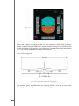
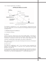
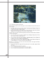
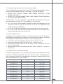
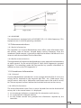

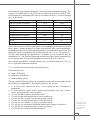

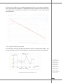
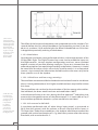


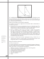

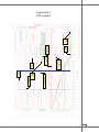

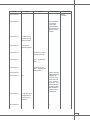
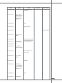
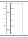
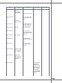
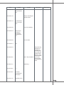

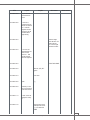
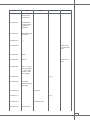
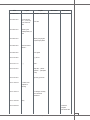


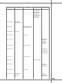


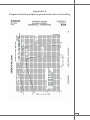


![[quote(var.text)]}](http://vs1.manualzilla.com/store/data/005937533_1-4dd3fe8a9b5a28fbfb6fbb268c8e3b66-150x150.png)