1
1
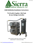
USER MANUAL/Installation Instructions
TV-22 with 12 gallon VAS-Tank
& Low Voltage Controller
Sierra Dental Products LLC
1931 W Gulf to Lake Hwy, Lecanto, FL 34461
800-240-5677 FAX 352-513-4801
Email: [email protected]
Website: WWW.dentalvacuums.com
TABLE OF CONTENTS
•
•
•
•
•
•
•
Page
Description………………………………………………………………………………………..Page
2
Congratulations……………………………………………………………………..…………….2
3
Customer support………………………………………………………………………………..3
4
Warranty Policy……………………………………………………………………………………
5
Safety…………………………………………………………………………………………………...
6
Sub Assemblies………………………….................................................................
7
Specifications………………………………………………………………………………………...
–
–
–
–
•
•
•
•
•
•
•
7
Site requirements…………………………………………………………………………………………………………….….
8
Product specifications……………………………………………………………………………………………………..…
Tank Specifications……………………………………………………………………………………………………… 9
Chassis Specifications …………………………………………………………………………..…………………. 10
System layout………………………………………………………………………………………
11
Installation…………………………………………………………………………………………..
12
Operation……………………………………………………………………………………………..
17
Plumbing flow diagram…………………………………………………………………………
19
Maintenance………………………………………………………………………………………….
20
21
Troubleshooting…………………………………………………………………………………….
22
Accessories…………………………………………………………………………………………….
CONGRATULATIONS
On the purchase of your Dual TRU-VAC Dry Vacuum System.
This state of the art dry vacuum is a very powerful, high
volume, efficient system, With the benefit of 2 motors for
complete backup recovery. 230 volt motors provides plenty
of vacuum on demand while maintaining multiple
operatories. Equipped with the Vortex Action Separator Tank
(VAS) your dual TRU-VAC dry vacuum system will ensure
efficiency, reliability, and savings of up to 200,000 gallons of
water usage per year.
Sierra Dental Products LLC.
www.dentalvacuums.com
2
CUSTOMER SUPPORT
We will be happy to help you with any questions or concerns
you may have about your TRU-VAC SYSTEM.
CONTACT US 24 HOURS A DAY 7 DAYS A WEEK
Sierra
SierraDental
DentalProducts
ProductsLLC
LLC
1931
1931W.
W.Gulf
GulftotoLake
LakeHwy
Hwy
Lecanto,
Lecanto,FLFL34461
34461
Call us
TOLL FREE
Karen Bennett
(352)527-1975
ADMINISTRATOR
Chuck Bennett
(603)897-5042
OPERATIONS MANAGER
Dave Rolerad
(603)493-3635
DIRECTOR OF MATERIAL
Matthew Ball
(352)208-7317
Mgr. TECH SUPPORT
Hayden Tucker
(916)330-7191
SALES MANAGER
Email us
[email protected]
Visit us on the web
www.dentalvacuums.com
https://www.facebook.com/sierradentalpumps
3
WARRANTY POLICY
Sierra Dental Products Limited Warranty
Warranty for the TRU-VAC Dry Vacuum System is limited to the original
purchaser of the unit. Sierra Dental Products is only obligated under this
warranty to the repair or replacement of defective parts or materials. The
defect(s) must be reported to Sierra Dental Products within the valid
warranty period.
Sierra Dental Products will examine the product to determine if the parts
are defective. Products that have been abused, neglected, or damaged by
being improperly installed/maintained are not covered by this warranty.
We are not responsible for work performed on the unit by any
unauthorized service agents.
Warranty Period
Warranty is valid only with the return of the warranty card within 30 days
of purchase for a period of 10 years.
Warranty Service and Return Policy
To obtain warranty service, product must be returned to Sierra Dental
Products for examination at the purchaser’s expense. All returns must be
authorized and a return material authorization (RMA#) number must be
obtained from Sierra Dental Products. Returned units must be properly
packaged for shipping. We are not responsible for shipping damages or
shipping charges. Sierra Dental Products will, at their discretion, repair or
replace defective parts. ***Note*** there is a 25% re-stocking fee on all
returns.
4
SAFETY
Use of the TRU-VAC not in compliance with the instructions specified in
this manual may result in permanent failure of the unit.
WARNING:
To prevent fire or electrical shock, do not expose this unit to
rain or moisture, excessive heat or improper ventilation.
ATTENTION USERS:
Alerts users of important
operating and maintenance
instructions. Read carefully to
avoid any problems
Warns users of a potentially
hot surface, and a danger of
burns
Warns users that
uninsulated voltage is
present and can cause
electric shock
5
SUB ASSEMBLIES
Low Voltage Controller
Motor Assembly
Motors, tanks and controllers may be ordered separately.
6
SPECIFICATIONS
SITE REQUIREMENTS
ELECTRICAL 230 &
115 VOLTS
SINGLE (-TV-12)
DUAL (-TV-22)
Maximum Circuit
Breaker Rating
15 amp
15 amp (Qty 2)
Or 30 amp
Minimum Wire Size 14 gauge
14 gauge (Qty 2)
Or 8 gauge
PLUMBING
SINGLE (-TV-12)
DUAL (-TV-22)
Minimum Exhaust
Vent Pipe
1 ¼” steel pipe
(DO NOT USE ANY
90 DEGREE
ELBOWS)
1 ¼” steel pipe
(DO NOT USE ANY
90 DEGREE
ELBOWS)
Minimum Drain
Line
1 ½” flex pipe or
1 ½” Sched. 40 PVC
1 ½” flex pipe or
1 ½” Sched. 40 PVC
1 ½” Schedule 40 PVC is
recommended for main feed
(SUCTION) lines running to
operatories from the TRU-VAC.
7
PRODUCT SPECIFICATIONS
ELECTRICAL
SINGLE (-TV-10)
DUAL (-TV-22)
Voltage
230 V-AC/115V-AC
230 V-AC
Operating Load
7 amps
10 amps X2
Startup Load
14 amps
14 amps X2
Frequency
50-60 Hz
50-60 Hz
VAS (TANK)
SINGLE (-TV-10)
DUAL (-TV-22)
Max Operators
6
12
Capacity
8 gallons
12 gallons
MAX Operating Temp.
214°F(101°C)
214°(101°C)
Storage Temp.
0 – 150(-18-66°C)
0 – 150(-18-66°C)
Relative Humidity
90%
(no condensation)
90%
(no condensation)
Cooling Fan
115 V-AC
115V-AC
ENVIROMENTAL
CONDITIONS
*Flammable anesthetic mixtures should not be located
anywhere around this unit.
8
TANK SPECIFICATIONS
TANK
Weight
Height
Width
Depth
Capacity
V.A.S
43 lbs.
40”
17”
15”
12 Gal.
FRONT
R. SIDE
9
CHASSIS SPECIFICATIONS
Chassis Weight
Height
Width
Depth
2015
34”
21”
20”
188lbs
34”
21”
20”
10
SYSTEM LAYOUT TV-22
Out To Operatories
Low Voltage
Controllers
Vacuum Gauge
Power Cord
230 VAC
2.3 HP
Motor
Cooling Fan
115 VAC
Check Valve/ Drain
1 ½” PVC
11
INSTALLATION
TV-22
The VAS tank can be installed in an
alternate area if necessary
12
CONT. INSTALLATION TV-22
5. Plumbing will be according to whether you mount the tank
above or beside the motor assemblies. All of the necessary
plumbing is provided for you. The difference between the 2
plumbing configurations, is only the length of the flex pipe that
makes the connection between the tank and the motor inlets.
Connect a proper drain to the bottom of the tank and route
this to the sewer. Assure that the tank drain is at a higher
elevation than the sewer inlet to allow the tank to drain
properly. ( 1 ½” Schedule 40 PVC is recommended)
13
CONT. INSTALLATION –TV-22
(REFER TO THE PLUMBING ILLUSTRATION)
5. The RED outlined area shows the correct positioning for
plumbing the motors together. The BLUE outlined area shows a
90° elbow, this will only be used if your (VAS) tank is mounted
beside the two motor assemblies. If this is the case, then you will
cut a section of flex hose that can reach from the motor inlet, to
the tank inlet. Slip the yellow nipples in the hose ends, and be
sure to tighten these down with the provided hose clamps. This
will be the connection between your motors and your (VAS)tank.
*If your system will have the (VAS) tank mounted above the two
motor assemblies DON’T use the 90° elbow. Cut a big section of
flex hose that can reach from the motor inlet, to the tank inlet.
Slip the yellow nipples in the ends, and be sure to tighten these
down with the provided hose clamps. This will be the connection
between your motors and your (VAS) tank.
14
CONT. INSTALLATION TV-22
FIG. 4
k
FIG. 5
8. Routing the exhaust to an outside vent
is very important, this reduces the heat
significantly. Also this will ensure that any
odor will leave the building. Wherever
the exhaust leaves the building assure
that outside elements such as rain/snow
& or foreign debris cannot make its way
into the exhaust. This could potentially cause harm to the
motor. The easier the exhaust can flow out of the motor
with minimum restriction the cooler the system will run.
This will prolong the life of the motor. Keep this in mind
when routing the exhaust, excessive length and multiple
turns will create more restriction.
15
CONT.
22
15
16
OPERATION
Use the red rocker
switch to turn the
controller on & off.
Turn the toggle switch to the
up/on position to turn the
pump on. Or to down on
position is used to control the
pump on/off with a remote
switch
If the system will
not turn on Always
check this fuse
first. Only replace
with 2.5 amp fuse.
17
CONT.
For use with an alternate remote switch ensure that the red
rocker switch is on, and the toggle switch is in the down/remote
position, this will allow you to control the system with a remote
switch
18
FROM
OPS.
TO MOTORS
DRAIN
19
20
TROUBLESHOOTING
PROBLEM
POSSIBLE CAUSE
POSSIBLE SOLUTIONS
NO SUCTION
a.
b.
c.
d.
a. Turn pump on
b. Contact Sierra Dental
Products LLC
c. Shut unit off for 20
seconds and turn it back
on
d. Contact Sierra Dental
Products LLC
e. Call your Local Plumber
f. Call Sierra Dental
Products LLC
Poor Or Low
Suction
a. Restricted air
a. Ensure that exhaust is
exhaust
ran according to
b. Restricted air suction
installation procedure,
Call Sierra Dental
Products LLC
b. Dirty Filter, Contact
Sierra Dental Products
LLC
Pump Does
Not Run
a. 230 Volt Circuit
a. Turn the circuit breaker
breaker is OFF
ON
b. Remote switch is OFF b. Make sure your remote
or not correctly
is ON, Contact Sierra
connected
Dental Products LLC
c. Electrical Problem
c. Call Sierra Dental
Products LLC
Pump not turned on.
Pump not running.
(VAS) tank is full.
Drain check valve is
clogged
e. Clogged drain
f. Kinked or collapsed
suction hose
Feel free to contact us for any troubleshooting issues.
21
ACCESSORIES
22