1
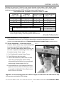
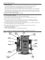
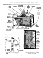
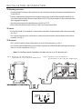
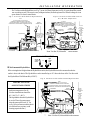
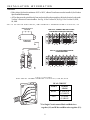
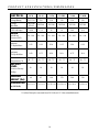
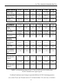
DENTAL VACUUM SYSTEM WE RECOMMEND DAILY USE OF CLEANSTREAM USER'S MANUAL A6732 ISO 9001 EN 46001 Air Techniques Inc. Hicksville, NY CONGRATULATIONS ON YOUR PURCHASE OF THE VACSTAR DENTAL VACUUM SYSTEM Your VacStar has been engineered to deliver maximum air flow at the ideal vacuum level without creating traumatic suction pressure that could harm patients’ delicate tissue. The VacStar is a water ring pump that produces consistent high-volume air flow, even with multiple users on-line. The balanced, corrosion free bronze impeller minimizes noise and a patented vacuum relief valve monitors and maintains constant uniform vacuum pressure. A capacitor-start type motor, with a highly reliable contactor and powerful transformer can be depended on to start every time. The VacStar is designed with everything accessible from the front, including the easy to clean solids collector. If your VacStar comes with an integral HydroMiser, water consumption will be reduced by up to 75%. If not, a HydroMiser can be integrated into your VacStar at a later date. The HydroMiser separates the liquid and gas discharge from the operatories. The gases are vented out and the liquid and its particulates are directed down the drain. The clean water extracted during this separation process is directed back toward the VacStar where it is mixed with fresh water and then directed into the pump chamber to create vacuum. This efficient reuse of water reduces the VacStar's fresh water consumption. Thousands of dentists have depended on the VacStar since 1987. Now that your practice has a VacStar, or a VacStar with the water saving HydroMiser, you too can depend on constant, uniform delivery of vacuum to your operatories and proven trouble-free operation. TABLE OF CONTENTS Sizing Guide . . . . . . . . . . . . . . . . . . . . . . . . . . . . . . . . . . . . . . . . . . . . 3 Maintenance . . . . . . . . . . . . . . . . . . . . . . . . . . . . . . . . . . . . . . . . . . . . 3, 4 Operating Information . . . . . . . . . . . . . . . . . . . . . . . . . . . . . . . . . . . . . . . . . . . 4 Key Parts Identification . . . . . . . . . . . . . . . . . . . . . . . . . . . . . . . . . . .. . . . . . 4, 5 Installation Information . . . . . . . . . . . . . . . . . . . . . . . . . . . . . . . . . . . . . . 6 - 8 Trouble Shooting . . . . . . . . . . . . . . . . . . . . . . . . . . . . . . . . . . . . . . . . . 9 Product Specifications/Dimensions . . . . . . . . . . . . . . . . . . . . . . . . . . . . . . . . 10 Site Requirements . . . . . . . . . . . . . . . . . . . . . . . . . . . . . . . . . . . . . . . . . . 11 Optional Accessories . . . . . . . . . . . . . . . . . . . . . . . . . . . . . . . . . . . . back cover Replacement/Reorder . . . . . . . . . . . . . . . . . . . . . . . . . . . . . . . . . . . . back cover 2 SIZING GUIDE Choosing the correct size VacStar for your practice depends on the number of HVE (High Volume Evacuator) and SE (Saliva Ejector) users anticipated. To assure optimum vacuum, the vacuum demands should not exceed the number of HVE and SE users shown in the chart below: RECOMMENDED NUMBER OF SIMULTANEOUS USERS VacStar 20 HVE’s + SE’s 2 + 0 1 + 1 0 + 4 VacStar 40 HVE’s + SE’s 3 + 0 2 + 2 1 + 4 0 + 6 HVE - High Volume Evacuator *VacStar 50 & 50H *VacStar 80 & 80H HVE’s + SE’s HVE’s + SE’s 4 + 0 7 + 0 3 + 2 6 + 1 2 + 4 5 + 3 1 + 5 4 + 4 3 + 6 2 + 8 SE - Saliva Ejector 1 + 10 0 + 13 * These combinations apply if both pumps are running together. If only one pump is running, use the Sizing Guide for VacStar 20 or 40. MAINTENANCE Daily Maintenance - Clean vacuum lines To maintain the cleanliness of your VacStar, including all the vacuum lines and tubing in your dental system, we recommend the daily use of CleanStream Evacuation System Cleaner. (see back cover) Weekly Maintenance - Clean solids collector Fig. 1 Caution: Solids collector may contain biologically hazardous material. Wear protective gloves. Note: Clean the solids collector DAILY during the first week of operation and during the first week of Evacuation System Cleaner usage. 1. Use CleanStream Evacuation System Cleaner. 2. Turn off the power and water supply. 3. Unscrew the solids bowl (counter clock-wise) and remove the screen and gasket. Remove all the sediment build-up from the bowl, screen gasket and inside housing. Rinse thoroughly. See Fig.1. 4. Reassemble the bowl, screen and gasket and screw tightly back onto the solids collector body or replace screen and bowl with Solids Collector Replacement Kit PN 55094 or PN 55880. Important: A worn or missing gasket and/or failure to tightly screw the bowl to the solids collector body will cause poor suction due to air leakage. DO NOT OPERATE THE VACSTAR WITHOUT THE SCREEN INSIDE THE FILTER BOWL. 3 MAINTENANCE In-Line Filter Kit If a VacStar is replacing a previous vacuum pump, an optional In-Line Filter, located in front of the inlet manifold (see Key Parts) is recommended. This In-Line Filter is designed to collect larger quantities of particulates from the discharge BEFORE it flows into the vacuum pump. Larger quantities of particulates may occur initially due to the VacStar's "pulling" power and to CleanStream Evacuation System Cleaner's ability to break down synthetic debris and proteinaceous deposits that build up in the vacuum lines. Check the filter daily and clean if required. In-Line Filter Kit for Single Vacuum Pumps #55078; for Twin Vacuum Pumps #55079. OPERATING INFORMATION AT THE START OF THE DAY Always TURN ON THE WATER before TURNING ON THE POWER. The VacStar may be turned on/off from a single, convenient location within the dental suite using a Remote Control Panel (See Optional Accessories). The vacuum level is factory preset at 10 In Hg (inches of mercury). This is the reading on the gauge when all HVE’s (High Volume Evacuator) and SE’s (Saliva Ejector) are CLOSED. Should this setting be too high for your needs, contact your dealer to readjust the setting. It is recommended that the system run continuously during the day. However, the VacStar can be turned off if suction is not required for a period of 15 minutes or longer. If one pump is being operated at a time, it is important to alternate pumps on an every other day schedule so that the pumps are used evenly. AT THE END OF THE DAY Always TURN THE POWER OFF, then TURN THE WATER OFF. KEY PARTS IDENTIFICATION - SINGLE UNITS Fig. 2 VACUUM RELIEF VALVE 24 V REMOTE WIRING FUSE HOLDER MOTOR DRIP COVER INLET MANIFOLD VACUUM BREAKER MOTOR WATER INLET VACUUM GAUGE WATER SOLENOID INTAKE SOLIDS COLLECTOR ELECTRICAL JUNCTION BOX 4 WATER INLET FILTER KEY PARTS IDENTIFICATION - TWIN UNITS Fig. 3 Front View VACUUM RELIEF VALVE VACUUM BREAKER HYDROMISER (ON VS50H AND VS80H ONLY)* VENT 24 V REMOTE WIRING CONTROL BOX ELECTRICAL CONNECTION BOX FRAME VACUUM GAUGE EXHAUST MANIFOLD INTAKE SOLIDS COLLECTOR LEVELING FEET BASE PLATE INLET MANIFOLD BYPASS VALVE EDUCTOR ASSEMBLY MAIN POWER SWITCHES Fig. 3a WATER SYSTEM CHECK VALVE WATER SOLENOID Fig. 4 Close up of Eductor Assembly WATER INLET CONNECTION TO HYDROMISER WATER FILTER CIRCUIT BREAKER (FOR 24V REMOTE WIRING) WATER SOLENOID CHECK VALVE FRONT OF VACSTAR TO LEFT PUMP VACSTAR BASE PLATE *VACSTAR 50H SHOWN - OTHER MODELS SIMILAR TO RIGHT PUMP 5 INSTALLATION INFORMATION Plumbing (water) lines - To assure that the VacStar provides optimum vacuum, incoming water pressure must be maintained between 20 and 100 psi. - If heavy combinations of particulates exist in the incoming water, an in-line filter should be installed. (See Accessories/Options for the Remote Control Water Valve.) This will prevent the VacStar's water inlet filter from clogging too frequently. - Incoming water temperature should be between 40°F and 75°F. - Water connection location is shown in Fig. 2 and 3a (water inlet connection). Suction - For VacStar 20 and 40, suction hose is connected at suction intake, found on intake solids collector assembly. See Fig. 2. - For VacStar twin pump units, suction hose is connected at suction intake, found on intake solids collector assembly. See Fig. 3. Drain lines - For VacStar 20 and 40 without a HydroMiser or an Air/Water Separator, see Fig. 5. - For VacStars without a HydroMiser or an Air/Water Separator, the effluent should be discharged into an open drain or a closed vented drain. See Fig. 6. Note: For VacStars without HydroMiser, the drain may be up to 36" above the unit. Fig. 6 VacStar 50, 80 without a HydroMiser or Air/Water Separator Fig. 5 VacStar 20, 40 without a HydroMiser or Air/Water Separator DRAIN INSTALLATION closed vented drain or 6 open drain pipe INSTALLATION INFORMATION - For VacStars with a HydroMiser (see Fig. 7) or an Air/Water Separator (see Fig. 8), gases should be vented out according to code. The waste water (with particulates) from the operatories can be discharged via an open drain or a closed vented drain. Fig. 8 VacStar with wall mounted Air/Water Separator Fig. 7 VacStar with built-in HydroMiser VENT vent to outside with 2" schedule 40 pipe (WARNING: CONDENSATION OF WATER WILL OCCUR IN VENT PIPING. AVOID ACCUMULATION OF WATER IN VENT, SLOPE PIPING TOWARD SEPARATOR) VENT vent to outside with 2" schedule 40 pipe (WARNING: CONDENSATION OF WATER WILL OCCUR IN VENT PIPING. AVOID ACCUMULATION OF WATER IN VENT, SLOPE PIPING TOWARD SEPARATOR) POWER CONNECTION AIR/WATER SEPARATOR WATER SUPPLY 1/2" COPPER TUBE TERMINAL WITH 1/2" FNPT SHUT OFF VALVE HYDROMISER WATER SUPPLY 1/2" COPPER TUBE TERMINAL WITH 1/2" FNPT SHUT OFF VALVE POWER CONNECTION 32" max. height 24 VAC 24 VAC INTAKE FROM MAIN LINE terminate with 1" FNPT fitting FLOOR SINK FLOOR SINK INTAKE FROM MAIN LINE - terminate with 1" FNPT fitting Note: VacStar 20, 40 installed in same manner DRAIN INSTALLATION closed vented drain open drain pipe or Wall-mounted HydroMiser If the existing drain is higher than the HydroMiser outlet, the HydroMiser must be mounted so that its outlet is above the drain. The HydroMiser can be installed up to 36" above the base of the VacStar with the HydroMiser Wall Mount Kit (#55087). Fig. 9 VacStar with wall mounted Hydromiser VENT vent to outside with 2" schedule 40 pipe (WARNING: CONDENSATION OF WATER WILL OCCUR IN VENT PIPING. AVOID ACCUMULATION OF WATER IN VENT, SLOPE PIPING TOWARD SEPARATOR) IMPORTANT NOTE: ALL INSTALLATIONS HYDROMISER Ambient temperature for all VacStar installations should be 40°- 104°F (5°- 40°C). The liquid drain from the HydroMiser or an Air/Water Separator must slope downward at least 1/4" for every 10 feet of run toward the drain. (Avoid local low sections, avoid creating traps in the line.) POWER CONNECTION 32" max. height 24 VAC WATER SUPPLY 1/2" COPPER TUBE TERMINAL WITH 1/2" FNPT SHUT OFF VALVE FLOOR SINK INTAKE FROM MAIN LINE - terminate with 1" FNPT fitting 7 Note: VacStar 20, 40 installed in same manner INSTALLATION INFORMATION Electric - If the voltage is below the minimum 105V or 205V, a Boost Transformer must be installed. (See Product Specifications/Dimensions) - All VacStars must be wired directly from an electrical box that complies with local electrical codes to the VacStar’s Electrical Connection Box . See Fig. 10 for VacStar 20, 40; Fig. 11 for VacStar 50, 50H, 80, 80H. FIG. 10 VACSTAR ELECTRICAL JUNCTION BOX - INTERIOR VIEW VacStar 20, 40 WIRED FOR 230 V0LTS AT FACTORY FOR 230 V, JUMPER TABS ARE PLACED IN POSITION SHOWN (FACTORY SET) POWER SUPPLY CONNECTIONS 2 - 3 L1 L1 L2 L2 5 - 6 FOR 115 V, PLACE JUMPER TABS IN POSITION SHOWN 1 - 2 3 - 4 6 - 7 FIG. 11 VACSTAR ELECTRICAL CONNECTION BOX -VacStar 50, 50H, 80, 80H DUAL CIRCUIT PUMPS GREEN BLACK RIGHT WHITE BLUE LEFT RED POWER LEADS (L1) BLACK (L2) WHITE (L1) RED (L2) BLUE * For Single Circuit connect Black and Red wires together (L1) and White and Blue wires together (L2). 8 TROUBLE SHOOTING PROBLEM POSSIBLE CAUSE POSSIBLE SOLUTIONS 1. Low suction. a. Water filter or solids collector clogged. a. Clean filter and/or collector. b. Check valves are stuck. b. Use a system cleaner like CleanStream; turn vacuum on and off to free check valve. If valve remains stuck, call your authorized Air Techniques dealer for repair service. c. Low water pressure. c. Raise water pressure. d. HydroMiser water recycler is clogged. d. Open bypass valve to run VacStar. Call your authorized Air Techniques dealer for repair service. e. HydroMiser clogged. e. Call your authorized Air Techniques dealer for repair service. f. Solenoids not operating. f. Call your authorized Air Techniques dealer for repair service. g. Restricted air exhaust g. Check air exhaust pipe size to make sure it conforms to spec; check for and clear possible restrictions in air exhaust system. a. Pumps off. a. Turn pumps on. b. Pumps not running. b. Call your authorized Air Techniques dealer for repair service. c. Inlet check valves stuck closed. c. Call your authorized Air Techniques dealer for repair service. d. Water inlet filter and/or Solids collector clogged. d. Clean filter. e. Suction hose collapsed. e. Hose needs to be replaced, call your authorized Air Techniques dealer for repair service. f. Solenoids not operating. f. Call your authorized Air Techniques dealer for repair service. a. Relief valve stuck closed. a. Call your authorized Air Techniques dealer for repair service. b. Relief valve filter clogged. b. Call your authorized Air Techniques dealer for repair service. a. Main switches off. a. Turn main switches on. b. Electrical problem. b. Call your authorized Air Techniques dealer for repair service. a. Inadequate water supply. a. Call plumber to improve water supply system. b. HydroMiser eductor clogged. b. Call your authorized Air Techniques dealer for repair service. c. Drain line collapsed. c. Hose needs to be replaced. Call your authorized Air Techniques dealer for repair service. d. Solenoids not operating. d. Call your authorized Air Techniques dealer for repair service. 2. No suction. 3. Excessive suction. 4. Pumps do not run. 5. Noisy Pumps. ALL INSTALLATIONS TO CONFORM TO LOCAL CODES 9 PRODUCT SPECIFICATIONS/DIMENSIONS ELECTRICAL VS 20 VS 40 VS 50 VS 50H VS 80 VS 80H Voltage Rating *115/230 230 230 230 230 230 Voltage Min./Max. *205/240 105 *110/125 205/240 205/240 205/240 205/240 205/240 *16/8 13.4 16 16 26.8 26.8 20 - 100 20 - 100 20 - 100 20 - 100 20 - 100 20 - 100 0.12 0.18 N/A 0.12 N/A 0.18 0.50 0.75 0.50 N/A 0.75 N/A 40 - 75 40 - 75 40 - 75 40 - 75 40 - 75 40 - 75 10 10 10 10 10 10 68 85 160 170 200 210 22 x 28 16 25 x 28 x 16 Full Load Amps WATER Inlet Water Pressure (PSI) Flow Rate Per Pump (gal/min) w / HydroMiser Flow Rate Per Pump (gal/min) w/o HydroMiser Water Temperature (°F) VACUUM LEVEL Preset at Factory (In Hg) SHIPPING WEIGHT (lbs) DIMENSIONS in. (HxWxD) 14 x 11x 11 17 x 11 x 11 22 x 28 x 16 25 x 28 x 16 *VacStar 20 may be converted from 230 Volts to 115 Volts at installation site. 10 SITE REQUIREMENTS ELECTRICAL VS 20 VS 40 VS 50 VS 50H Min. Circuit Breaker Rating 20A 20A 30A 30A Wire Size AWG (Min. Gauge) 12 12 10 10 2 ea. 12 or 1 ea. #8 2 ea. 12 or 1 ea. #8 #67002(230V) #67500(115V) #67002 #67002 #67002 #67002 2 ea. #67002 2 ea. VS 20 VS 40 VS 50 VS 50H VS 80 VS 80H 16 22 32 32 44 44 *Boost Transformer PLUMBING Min. CFM @ 0" Hg Air Exhaust Ambient Temperature Overhead Plumbing Main Line Dia. Min./Max ID in inches End Fitting Max Riser Diameter Overhead Main Line Floor Plumbing Main Line Dia. Min./Max. ID in inches End Fitting Max Branch Line Dia. Min./Max. ID in inches 2" schedule 40 pipe 40° - 104°F (5°- 40°C) VS 80 VS 80H 2 ea. 20A 2 ea. 20A or 1 ea. 40A or 1 ea. 40A 2" schedule 2" schedule 2" schedule 2" schedule 2" schedule 40 pipe 40 pipe 40 pipe 40 pipe 40 pipe 40° - 104°F 40° - 104°F 40° - 104°F 40° - 104°F 40° - 104°F (5°- 40°C) (5°- 40°C) (5°- 40°C) (5°- 40°C) (5°- 40°C) 1 / 1½ 1¼ / 2 1¼ / 1½ 1¼ / 1½ 1½ / 2 1½ / 2 1" FNPT 1" FNPT 1" FNPT 1" FNPT 1" FNPT 1" FNPT ½” ID ½” ID ½” ID ½” ID ½” ID ½” ID 1 / 1½ 1¼ / 2 1¼ / 1½ 1¼ / 1½ 1½ / 2 1½ / 2 3/4" FNPT 3/4" FNPT 1" FNPT 1" FNPT 1" FNPT 1" FNPT 3/4 / 1½ 1 / 1½ 1 / 1½ 1 / 1½ 1 / 1½ 1 / 1½ NOTE: Suction piping must slope at least a ¼” for each 10 feet of run towards the pump. Use PVC Schedule 40 or Copper Type M. * Use Boost Transformer only if voltage is expected to fall below 105/205 Volts during operation. ALL INSTALLATIONS MUST CONFORM TO LOCAL CODES 11 ACCESSORIES/OPTIONS DESCRIPTION MODEL PART NUMBER HydroMiser Wall Mount Kit VacStar 50H, 80H 55087 Remote Control Panels with 24V switches VacStar 20, 40 VacStar 50, 50H, 80, 80H 53250 or 53251 53113 or 53149 Remote Control Water Valve, with filter All VacStar Models 53020 (24V) - 3 4" pipe 53020-1 (115V) - 3 4" pipe 53170 (24V) - 1" pipe 53171 (115V) - 1" pipe Boost Transformer VacStar 20 VacStar 20, 40, 50, 80 VacStar 80, 80H 67500 (115V) 67002 (230V) 2 each 67002 (230V) HydroMiser Kit VacStar 20 VacStar 40 VacStar 50 VacStar 80 H-2 H-4 56041 56042 Air/Water Separator VacStar 20, 40, 50, 80 55540 In-Line Filter Kit VacStar 20, 40 VacStar 50, 50H, 80, 80H 55078 - 3 4" pipe 55079 - 1" pipe CleanStream Evacuation System Cleaner All VacStars 57660 57640 Starter Kit 1 Box of 32 Packets REPLACEMENT/REORDER DESCRIPTION MODEL PART NUMBER Solids Collector Replacement Kit VacStar 20, 40 VacStar 50, 50H, 80, 80H 55880 55094 Air Techniques is a leading manufacturer of dental equipment from air compressors and vacuum systems to x-ray film processors, intraoral video cameras, and most recently air abrasion, rapid curing and bleaching and digital imaging systems. We have been manufacturing quality products for the dental professional since 1962. A/T ScanXTM A/T SLCTM A/T 2000® XR AirDentTM II / AirDent II CSTM AirStar® ARC Light® IIM CleanStreamTM Peri-Pro® STSTM VacStarTM VistaCam OmniTM CORPORATE HEADQUARTERS 70 Cantiague Rock Road, Hicksville, New York 11801 Telephone: (516) 433-7676 Fax: (516) 433-7684 1-800-AIR-TECH www.airtechniques.com WESTERN FACILITY 291 Bonnie Lane, Corona, CA 92880 Telephone: (909) 898-8555 Fax: (909) 898-7646 1-800-822-2899 PN 55151 Rev. H VacStar is a trademark of Air Techniques Inc. © Copyright 2004 Air Techniques Inc.