1
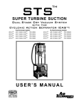
STERI-VAC
CENTRAL SUCTION SYSTEM
INSTALLATION MANUAL
This is a general installation manual for installing Steri-Vac Central Suction Systems.
For detailed information see specific technical sheet.
These are high-volume suction systems, designed for the removal of wet wastes
(saliva, water, chippings, etc.) from the dental operatory.
The main components of these units are:
1)
2)
3)
4)
Power Source
Collection Center (Canister)
Pipings & Fittings
Maintenance
STERI-DENT
2364 Leicester Road
PO Box 175
Leicester, NY 14481-0175
800-346-DENT (3368) Toll-free in the U.S.
Phone: 585-382-3223
Fax: 585-382-3736
1)
Vacuum Power Source, Low Voltage Control Box and Electrical Equipment
Each power source consists of a motor assembly with low voltage (on-off) controls. All motors are
equipped with three-wire cord and grounding plug. Only normal house current is needed as the
current demand is 6 – 12 amps depending on type used. All motors have permanently lubricated
sealed bearings. Each control box has a pilot light, overload circuit breaker and motor test switch.
Using the momentary test switch, the motor can be turned on without using the low voltage friction
switches in the operatories.
Motor Cooling. A fresh air supply for motor cooling is a MUST. Do not install the motor in a hot
or confined area without taking the necessary precautions of bringing fresh air into the area. Any
vents for an intake must have at least 1½ square feet of unobstructed area. Furthermore, exhaust
air is hot and should be vented to the outside. If installed in a confined area such as a closed or
closed cabinet, a fresh air supply should be supplied to the confined space and/or the power unit.
DO NOT use PVC pipe for exhausting. For exhausting the regular, heavy duty , and Steri-Vac
Units, the 3” flexible tubing is satisfactory. For long exhaust runs of over 25 feet, use sheet metal
ducting for all power units.
Master Switch. A master on-off switch should be provided at the same location as other master
controls – compressor, air conditioner, etc.
Low Voltage Wiring. Use test switch on control box to check the motor BEFORE connecting
low voltage wires. After checking the motor, connect the low voltage wires from the control box to
the wiring coming from the switches in the operatories, which are hooked up in parallel. Low
voltage wires can be taped to the PVC pipe. However, in concrete floor installations, low voltage
wires MUST be installed with strict adherence to electrical codes. If necessary, consult an
electrician.
Concrete or Slab Floor. This installation applies to new offices or those being remodeled and/or
when no basement or crawl space is available. If possible, install the 1½” PVC pipe only after the
other trades are through with their work but BEFORE the concrete is poured. Make sure that
the other workmen do not damage the installation of the tubing and keep supervisory personnel
advised of this responsibility.
Protect the pipe against damage by covering with sand or vermiculite fill. Watch while the
concrete is being poured so that the PVC tubing is not damaged by the tamping or spreading of
concrete.
2)
Collection Center (Canister)
The canister is a trap and separator. Waste material is carried into it by the vacuum air stream and
held temporarily until the power unit is turned off. The canister is located between the vacuum
inlets in the operatories and the power plant. Select the canister location carefully using these
guidelines:
A. Access to plumbing drain. The canister should be located as low as possible (above
the drain) to avoid excessive water lift. The top of the canister cannot be installed
more than 40” above the vacuum tubing main line. The canister can be installed at
any convenient distance below the vacuum tubing main line. The check valve must be
mounted vertically and above the plumbing drain to permit the emptying of the canister
by gravity. Do not solidly plumb in the check valve as it might eventually have to be
changed.
B. The canister must be installed where it is accessible, leaving room for the cover to be
removed for periodical visual inspection and cleaning. The canister need not be
mounted below the level of the inlets. It can be hung on the wall of the laboratory,
utility room, darkroom, garage, etc. (Mount as low as possible to avoid excess water
lift). Make sure that the canister is mounted at a reasonable level with no strain on the
connecting pipes and fittings. Canister cover must be in place for the suction
system to operate. Always disconnect the power plant from the electrical outlet
BEFORE removing or replacing the cover to avoid possible injury.
NOTE: The canister will only drain when the motor is off. It is necessary for the user to shut the
unit off periodically to relieve the vacuum and allow the gravity drain to work. Should the canister
fill up, suction will automatically stop and the flow of fresh air to the motor will stop. If this
happens, the user MUST immediately turn off the motor and allow the canister to drain.
Check Valve. The check valve is attached to the bottom of the canister as shown on the last page.
It remains closed while the vacuum is on. When the power source is off, the check value will open
and allow the fluid waste in the canister to drain by gravity into the plumbing system.
CAUTION: Do not operate your system unless the check valve is correctly installed. It
MUST be installed with arrow pointing away from the canister in direction of flow. Do not
bypass the valve. In case of malfunction, repair or replace immediately; otherwise the system
will be damaged.
Plumbing Requirements. In most localities, the Steri-Vac System is considered foremost a
vacuum system and therefore generally not under jurisdiction of plumbing authorities. However,
the connection (direct or indirect) from the check valve to the drain is considered part of the
plumbing and must be installed per local plumbing codes.
3)
Vacuum Piping and Fittings
The vacuum piping connects the inlets to the collection center, and should be scheduled 40 PVC
(High-impact Polyvinyl Chloride) and be 1½” inside diameter. The pipe is corrosion proof,
durable, and will not burn. It is lightweight and can easily be cut with a hacksaw, and is available
from most plumbing and hardware stores.
Please Note: PVC plumbing is preferable to any other material, including copper, for Highvolume, Low-Vacuum Oral Evacuation. PVC will carry a moist air stream mixed with chemicals,
and will not corrode even by electrolytic action like copper and other metals. The pipe has
sufficient wall thickness and strength for oral evacuation and without positive internal pressure.
Branch Connections. Branch connections are either of the “T” type or the “Y” type. Make sure
that these parts are installed so that the curve of flow section is toward the canister.
Otherwise, air turbulence can result in decreased function and clogging. Where the pipe line
branches in two different directions, use a “T” shaped part.
Joining Pipes and Fittings. Before joining the parts, make sure that each section of the pipe has
been cut to the correct length. We suggest that the piping system be assembled and checked out
before cementing the joints.
Cementing. Apply the PVC cement in a ½” band around the outside, at the end of the pipe, and
also to the socket of the fitting. Then slip the pipe into the fitting with a twisting motion. The PVC
cement sets very quickly; therefore the fitting should be lined up immediately. A mistake can only
be corrected by replacing the wrong part(s) with the correct one(s) using a coupling. Do not
cement pipes to canister or power unit; this will restrict removal or replacement in case of repair
or service. These joints can be secured with vinyl tape.
Pipe Support and Pitch. Because PVC pipe is lightweight and carries only a moist air stream,
minimal support is necessary. Place straps approximately 6 feet apart. A pitch of ¼” for every 10
feet of pipe is the minimum recommended.
Special Installations. Dental Unit Inlets: If the vacuum inlet is to be mounted within a dental
unit, adapters for connecting the PVC pipe can be obtained from your local hardware or plumbing
supplier.
Overall Dimensions of Power Units and Canisters
Power Unit
Height
Width
Depth
Steri-Vac Heavy Duty and Standard
19”
16”
18”
Canister – Cat. No.
Capacity
Diameter
Height*
SV-5
5 Gal.
14”
15”
* Height measured without check valve. Add 5” for check valve.
For Most Efficient Installation…
These points should be followed for efficient installation and MUST be followed to protect the owner’s
warranty policy.
1)
A fresh air supply for motor cooling is a MUST.
2)
Heated exhaust air should be vented to the outside. If exhausted into the room, exhaust air
should be directed away from the power unit so as not to interfere with the motor cooling
cycle. THE EXHAUSTED AIR SHOULD NEVER BE EXHAUSTED IN THE SAME
ROOM WITH THE AIR COMPRESSOR OR FURNACE TO AVOID CROSS
CONTAMINATION OF AIRBORNE BACTERIA.
3)
The top of the canister can not be installed more than 40” above the vacuum tubing main
line.
4)
A master on-off switch is to be turned on and off each morning and evening; this will
prevent accidental/unnecessary operation, and prolong motor life.
5)
Upon installation, make sure the drain line from the check valve (½ copper) does not extend
into the water level to prevent siphoning back into the canister.
Maintenance instructions for your Steri-Vac Suction System
Regular care of your Steri-Vac Central Suction System is easy but important. Following the instructions
below will keep your system in good working order and is required to fulfill all your warranty obligations.
Daily:
1) At the end of each working day, draw at least one pint of oral evacuation cleaner through each
mouthpiece and hose used that day. Let the system run for about one minute to make sure the liquid
is completely drawn through.
2) It is necessary to shut off the system periodically – about ten minutes every few hours –
to relieve the vacuum, thereby allowing gravity to drain the canister automatically. If the
canister fills up, it will close off suction but the power unit will continue to run, and the
motor will labor without a free flow of air. This will shorten motor life. If this happens the
power unit MUST be turned off, breaking the suction in the canister and allowing it to drain.
Weekly:
1) Remove all inlet adapters and pour about one quart of oral evacuation cleaner into each
inlet. Let stand for about ten minutes. Then purge the system, starting with the inlet in the
operatory farthest from the collection canister:
2) Turn on the system and rapidly open and release the flap of the inlet faceplate against the
vacuum in the line. This will cause an inrush of air, creating a shockwave that will carry
debris into the canister that might have accumulated in the line. The same procedure should
be followed in sequence for each inlet.
Monthly:
1) Inspect the canister and remove any debris, or sedimentation rings using a brush and oral
evacuation cleaner.
2) Inspect and clean the catch screen.
Should you notice during the cleaning (or any other time) that the liquid stays in the canister
and does not drain quickly, the check valve at the bottom is probably clogged and not
functioning properly. Use a BLUNT instrument to probe carefully around the valve and
flush with plenty of oral evacuation fluid cleanser. Do not operate system until the
blockage is corrected.