1
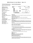
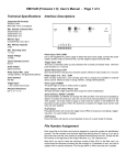
RM31A (v1.3) User’s Manual - Page 1 of 4
Technical Specifications
Sound Card Descriptions
Firmware Version
1.3
Number of Sound Cards per Chasis
1 ~ 12
Supported File Formats
Windows WAV (8 & 16 bit)
MP3 (ISO 11172-3 up to 44.1KHz)
Memory Type
CompactFlash card, type I
Max. Memory Capacity per Card
2 GB
Max. Recording Time
> 1 hour per card
Audio Output
Stereo line level
Relay Contact Rating
12A @ 120VAC, 10A @ 240VAC/28VDC
Serial Interface
RS-485
Trigger Input
1, dry contact closure type
Internal Power Supply
IN: 110/220 VAC 50/60 Hz (auto switch)
OUT: 12VDC, 4.2A
Power Consumption
300mA max. per card
Chasis Dimensions
440mm x 88mm x 176mm
(2U 19” rack mount)
POWER Light
The power light is turned on when power is applied. The power light is visible through the
system’s front panel.
LINE OUT: 1/8” Stereo Phone Jack
This jack provides single ended line level output for external amplification.
RS485 Jumpers: J1 & J2
Keep the shorting caps on the right two pins (default setting) whether the RS-485 port will be
used or not.
CLOCK Jumper: J3
Place the shorting cap on the top two pins (default setting) to run all cards with the common
clock that the backplane provides. This way all cards will be kept in perfect synchronization
with each other. If the shorting cap is placed on the bottom two pins, the card will use its own
internal clock.
Caution! Please turn off power before adding/removing sound cards or flash cards.
Back Panel Descriptions
The following terminals are common to all sound cards.
12V: This is a 12VDC output from the internal power supply. You can get some power here
for other purpose if the slots are not fully populated. Each empty slot gives 300mA of
spare current that you can use elsewhere.
GND: Ground.
485+, 485-: These are RS-485 connections common to all sound cards. In order to use the
RS-485 port, each sound card must be configured properly - refer to the Sound Card
Configuration section for descriptions.
Each sound card has a set of the following terminals on the back panel:
AUDIO: Stereo line out.
GND: Ground.
TRG: Trigger input, maximum input voltage is 24VDC.
RST: Reset input, short to ground for at least 100 ms.
N.O.: Normally open contact of the relay.
COM: Common contact of the relay.
N.C.: Normally closed contact of the relay.
The relay will be automatically activated during audio playback except when the card is
configured in the Script or the Serial mode. In the Script or the Serial mode, the relay may be
activated with specific commands only.
RM31A (1.3) User’s Manual - Page 2 of 4
File Number Assignment
Relay Control
Sound files on the flash card must be assigned a unique number
for identification purposes. The file number must be three digits
long and follow certain rules based on the particular Input mode
(see the Input Mode section for more details).
The relays are controlled differently in different modes:
The file number should be added in front of the original filename,
e.g. “001TEST.WAV”. Long file names (names longer than 8 letters, or in lower case, or with special characters) are acceptable
but will decrease the maximum number of files that can be stored
on the flash card due to FAT16 file system limitation.
Trigger Input Configuraton
The trigger input can be configured to operate in many different
ways by adding to the flash card a plain text file called MODE.TXT.
Put three upper case letters in this file according to the following:
First Letter = Input Mode
D = Direct mode (default)
The trigger always activates file 001.
S = Sequential mode
The trigger sequentially activates, one file at a time, a list of files
starting from 001. The sequence resets to 001 when the next file
number is missing. For example, if there are a total of four sound
files on the flash card numbered 001, 002, 004 and 005, then only
001 and 002 will be played because 003 is missing.
Second Letter = Play Mode
N = Non-interruptible mode (default)
The file plays one time and is not interruptible.
I = Interruptible mode
The file plays one time but is interruptible if the input is triggered
again. However, the trigger mode (see below) must be either M or
B in order for the interruptible mode to work.
H = Hold mode
The file plays for as long as the input is triggered (looping if necessary) and stops as soon as the input is not triggered.
S = Script mode
Refer to the Script Mode section for descriptions.
Third Letter = Trigger Mode
C = Close mode (default)
An input is triggered when it’s at 0V (ground). Therefore if an input
is tied to the ground through a switch, it is triggered for as long as
the switch is closed.
O = Open mode
An input is triggered when it’s at +5V. Therefore if an input is tied to
the ground through a switch, it is triggered for as long as the switch
is open (because the inputs are internally pulled up to +5V).
M = Make mode
An input is triggered when it goes from +5V to 0V. Therefore if an
input is tied to the ground through a switch, it is triggered at the
very moment when the switch is closed.
B = Break mode
An input is triggered when it goes from 0V to +5V. Therefore if an
input is tied to the ground through a switch, it is triggered at the
very moment when the switch is opened.
Serial Interface
Relays are controlled by serial commands only. Refer to the Serial
Commands section for details.
Script modes
Relays are controlled by script commands only. Refer to the Script
Mode section for details.
All other modes
The relay will automatically turn on during playback.
Trouble Shooting Guide
1. Plays no sound at all.
a. File numbers are not assigned properly.
b. The system is in the wrong mode due to missing or incorrect
configuration file.
c. If the flash card is inserted when the power is on, the system
may not work. To fix this problem, turn the power off for a few
seconds to reset the system.
d. Some CF cards, especially if they have been used in digital
cameras, need to be reformatted with the FAT16 file system.
2. Plays wrong files.
a. File numbers are not assigned properly.
b. The system is in the wrong mode due to missing or incorrect
configuration file.
RM31A (v1.3) User’s Manual - Page 3 of 4
Script Mode
Examples
SSM
N001=F047,XN1,W00030,F899,XF1,J168
H002=F002
H004=F055
I168=F001,W36000,J168
END
Instead of playing just a single file, the Script mode executes a
script of commands. Note that the relay will not turn on/off automatically in the Script mode. It must be explicitly controlled using
the BN/BF script commands.
Written in the configuration file (MODE.TXT) using plain ASCII text,
the script consists of multiple lines each containing the commands
for a particular trigger in the following format:
?nnn=Command1,Command2...
Here “nnn” is the trigger number and “?” is one of the following:
N - Non-interruptible
Execution of this trigger is not interruptible.
I - Interruptible
Execution of this trigger is interruptible. However, the trigger mode
must be either M or B in order for the interruptible mode to work.
H - Holdable
Execution of this trigger continues for as long as the trigger is
present, repeating itself if necessary. The execution stops immediately when the trigger is no longer present.
For the DS (Direct Script) mode, there is only one trigger (001). For
the SS (Sequential Script) mode, there can be up to 99 triggers
(001 ~ 099) to be executed sequentially.
In addition to the direct triggers, there are also indirect triggers. An
indirect trigger can be activated only by jumping from another trigger using the Jump command.
These are the script commands:
SSM is not really a script command, but it tells the system to enter
the Sequential Script Make mode.
When the input is triggered, the system start executing trigger N001.
Since this trigger is non-interruptible, it will always executes to the
end. Trigger N001 is executed as the following:
-
play file #047,
turn on the relay,
wait 3 seconds,
play file #899,
turn off the relay,
jump to trigger 168.
Trigger 168 is executed as the following:
- play file #001,
- wait 60 minutes,
- jump back to itself.
Since trigger 168 is interruptible (thanks to the letter ‘I’ in front of
168), this endless loop will be broken when the input is triggered
the next time. At that time, the next sequential trigger (002) will be
executed.
Trigger H004 will never be executed because a) trigger 003 does
not exist, b) trigger H004 is not jumped to from any other trigger.
Fnnn - play File #nnn
Example: F168 plays file #168.
Background Music Example
Wnnnnn - wait nnnnn units of 0.1 second
Example: W00020 waits 2 seconds.
The automatic execution feature can be used to play background
music while no trigger is being executed. For example,
Jnnn - jump to trigger #nnn
Example: J007 jumps to trigger 007.
XN1 - turn on the relay
XF1 - turn off the relay
END
Always add the word END at the end of the entire script. You may
add any comments for your own reference after END.
Important Notes
- Script lines must be separated by carriage returns (the Enter key).
- A script line is limited to 128 characters, excluding ‘=’ and ‘,’. If
more space is needed, use the Jump command.
Automatic Execution of Script 000
Upon powerup or reset, the system will automatically executes script
000 once if it exists.
SSC
I000=F123,J000
N001=F001,J000
N002=F002,J000
N003=F003,J000
END
Here file #123 is looped continuously but can be interrupted by
triggering the input. At the end of each interruption, the script always jumps back to trigger 000 so file #123 restarts again, although
from the beginning instead of where it left off.
RM31A (v1.3) User’s Manual - Page 4 of 4
Serial Interface
The serial interface is RS-485. In order to enable it, you must move
the internal jumpers J1 and J2 to the “ON” position. Also, the configuration file (MODE.TXT) must contain an unique device address
ranging from “01” to “99”, but not “65”.
The hardware protocol is 9600 baud, 8 data bits, no parity and 1
stop bit. The communication relies on software handshake on a
per-byte basis. The controlling device (DTE) must not send the
next byte until it receives the confirmation for the previous byte.
However, there are some exceptions as described later.
A communication session always starts with the addressing process. The DTE first sends out an ASCII ‘A’ which, as one exception, will not be acknowledged by any system. The DTE then sends
the address. If there is a system with the matching address, it will
respond by sending back an ASCII ‘a’ within 100 ms. Otherwise
the addressing process has failed and should be restarted.
Relay On
DTE Sends: X
System Confirms: x
Relay Off
DTE Sends: Y
System Confirms: y
Designate Group File
DTE Sends: D### (### is the three-digit file number)
Player Confirms: d### (### is the same file number as above)
Designate file ### as the Group File in order to get ready for the
Group Play command. The Group File is automatically un-designated after the execution of the following commands: L, P, S. This
command must be issued when the system is idle.
Group Play
DTE Sends: G
System Confirms: none
Address 100 is the broadcast address for talking to all systems at
once - no confirmation will be sent from any system throughout the
entire command. The broadcast address cannot be use with the
following commands: B, H, L, P.
Start playing the Group File if one is designated. Use this command to start multiple systems at the same time.
Once the addressing process is finished successfully, the DTE can
start sending the serial command, one byte at a time after the previous acknowledgement is received (usually within 100 ms). If any
acknowledgement is missing or invalid, the whole session should
be aborted.
The serial port can be easily tested by using a Windows utility program called “HyperTerminal”. HyperTerminal allows you to send
and receive data through the PC’s serial port. Refer to its help menu
for more information.
Serial Commands
Play File
DTE Sends: F### (### is the three-digit file number)
Player Confirms: f### (### is the same file number as above)
Play file ### once if it exists, otherwise ignore the command. If the
system is playing or being paused when the letter ‘F’ is received, it
will send an error code ‘e’ and ignore the command.
Loop Play
DTE Sends: L### (### is the three-digit file number)
Player Confirms: l### (### is the same file number as above)
Play file ### repeatedly if it exists, otherwise ignore the command.
If the system is playing or being paused when the letter ‘L’ is received, it will send an error code ‘e’ and ignore the command.
Stop
DTE Sends: S
System Confirms: s
Stop the current playback if any.
Pause
DTE Sends: P
System Confirms: p
Pause the current playback if any.
Resume
DTE Sends: R
System Confirms: r
Resume the paused playback if any.
Busy?
DTE Sends: B
System Confirms: b (if playing or paused) or s (otherwise)
Testing the Serial Interface
The first step is to create a text file called “MODE.TXT” on the flash
card. Put only two letters in the file: 66. This will put the player into
the Serial mode with an address of 66. You also need to put a test
sound file on the flash card named 001.WAV (or 001.MP3).
The next step is to connect the player to the PC using a proper
cable. If the PC does not have a RS-485 port, install a RS-232 to
RS-485 converter.
Run HyperTerminal and make a new connection with these parameters: 9600 baud, 8N1, no flow control. Now we are ready to send
the following commands to the player:
We Type
Player Confirms
-----------------------------------------------------A
(nothing)
B
a
F
f
0
0
0
0
1
1
...... (file playing) ......
A
(nothing)
d
(nothing)
S
(nothing)
...... (playback stopped)......
Note that the ASCII code for the letter B is 66 which is the address
we assigned to the player. The ASCII code for the letter d is 100
which is the broadcast address - we could have also used the “ABS”
command sequence here.
If you type a wrong letter during the test, the player will respond
either with a letter e or nothing at all, depending on the situation. In
this case, you need to restart the entire session.