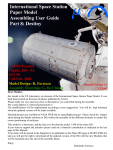
1
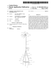
US 20060215391A1
(19) United States
(12) Patent Application Publication (10) Pub. No.: US 2006/0215391 A1
(43) Pub. Date:
Jones et al.
(54)
LIGHTED DETAIL BRUSH
(76) Inventors: Terry G. Jones, Austin, TX (US);
Timothy J. Crowley, Marfa, TX (US);
Sep. 28, 2006
Publication Classi?cation
(51)
Lynn Crowley, Marfa, TX (US)
(52)
Int. Cl.
A47L 9/30
F21V 33/00
(2006.01)
(2006.01)
U.S. c1. ............................................ .. 362/91; 362/109
Correspondence Address:
H. DALE LANGLEY, JR.
THE LAW FIRM OF H. DALE LANGLEY, JR.
PC
610 WEST LYNN
AUSTIN, TX 78703 (US)
(57)
ABSTRACT
A handheld implement, such as, for example, a brush,
detailer, applicator, or the like, includes a housing and a
Work element connected to the handle. The implement also
includes a light, a poWer source connected to the light, and
a sWitch for turning on and oiT the poWer source for
(21) Appl. No.:
11/321,980
(22) Filed:
Dec. 29, 2005
the housing When the implement is not in use, and can be
extendable from the housing When the implement is in use.
Related US. Application Data
The light, Via switching the light on or o?“, selectively
(63) Continuation-in-part of application No. 11/088,294,
implement is employed or operates. The Work element is, for
illuminating the light. The Work element is concealable in
illuminates a surface on Which the Work element of the
?led on Mar. 24, 2005.
example, bristles, and the light is a low power bulb or LED.
/ 300
Patent Application Publication Sep. 28, 2006 Sheet 1 0f 8
z I
104
‘
108
FIG. 1
US 2006/0215391 A1
Patent Application Publication Sep. 28, 2006 Sheet 2 0f 8
(112/1121)
US 2006/0215391 A1
[250
L|GHT(S)
(‘254
720\
POWER
14
FIG. 2B
114
110
f
300
400
x
114
110
Patent Application Publication Sep. 28, 2006 Sheet 3 0f 8
514
FIG. 5
514
FIG. 6
US 2006/0215391 A1
Patent Application Publication Sep. 28, 2006 Sheet 4 0f 8
7
FIG. 7
FIG. 8
US 2006/0215391 A1
Patent Application Publication Sep. 28, 2006 Sheet 5 0f 8
914
FIG. 9
[900
914
US 2006/0215391 A1
-
10a0\ \MI
FIG. 10
Patent Application Publication Sep. 28, 2006 Sheet 6 0f 8
US 2006/0215391 A1
7278
1222
7218
FIG. 12/}
1210\_
FIG. 1Z8
Patent Application Publication Sep. 28, 2006 Sheet 7 0f 8
US 2006/0215391 A1
Patent Application Publication Sep. 28, 2006 Sheet 8 0f 8
US 2006/0215391 A1
Sep. 28, 2006
US 2006/0215391Al
LIGHTED DETAIL BRUSH
CROSS-REFERENCE TO RELATED
APPLICATIONS
[0001] This application is a continuation-in-part of US.
patent application Ser. No. 11/088,294, ?led on Mar. 24,
2005, titled “Lighted Cleaning Implement”, incorporated
herein by this reference.
BACKGROUND OF THE INVENTION
[0002] The present invention generally relates to cleaning
implements, such as brooms, mops, Whisk brooms, coating
applicators, dusters, and brushes and, more particularly,
relates to illuminating features incorporated in handheld
[0008] Yet another embodiment of the invention is a mop
having a handle and a mop head connected to the handle.
The mop includes a light in the handle, a poWer source
connected to the light, and a sWitch for turning on and off the
poWer source.
[0009]
Another embodiment of the invention is an imple
ment comprising a handle and a cleaning feature connected
to the handle. A light is connected to the implement.
[0010] Yet another embodiment of the invention is a
method of using an implement. The method includes con
necting a light to the implement.
[0011]
Another embodiment of the invention is a method
of using an implement. The method includes illuminating by
detail brushes and other implements.
the implement.
[0003] Brushes, brooms, mops, dusters, Whisk brooms,
[0012] A further embodiment of the invention is a system
for brushing. The system includes a bristle, a housing
and the like are conventionally quite standard, basic, and
featureless. Improvements to these conventional implements
have typically been limited to varied materials, for example,
horsehair, natural straW bristles, cotton, or similar materials
as bristles and brush surfaces, mop heads, cleaning surfaces,
paint applicators, and Wood handles, have been replaced
With plastics or other synthetics in certain instances. Not
Withstanding these limited improvements, the conventional
designs for these implements have remained generally
unchanged for many years.
[0004] A reason that these conventional designs have
remained unchanged is that consumers desire these imple
ments to be fairly inexpensive and primarily functional. In
order to limit costs, manufacturers have maintained basic
designs, Without any signi?cant improvements or neW fea
tures. Presently, costs for simple electronics have dropped
substantially, and requirements to poWer such electronics
have been vastly reduced and miniaturized. For instance,
light bulbs, batteries, and circuits have become quite inex
pensive to make and maintain. Also, poWer consumption
required for bulbs and circuits, particularly With neWer light
containing the bristle, the housing being hand holdable, and
a light connected to the housing.
[0013] Another embodiment of the invention is a hand
implement for Work on a surface. The hand implement
includes an elongate housing having an operational end, a
Work element connected to the operational end, a light
connected to the housing for selectively illuminating the
surface, a poWer source contained Within the housing and
connected to the light, and a sWitch connected to the poWer
source for turning on and off the poWer source to the light.
[0014] Yet another embodiment of the invention is a hand
implement for Work on a surface. The implement includes
parallel sides joined by an end, a Wheel rotatably connected
betWeen the parallel sides, a Work element connected to the
periphery of the Wheel, a light connected to the Wheel for
selectively illuminating the surface, a poWer source con
nected to the light and contained Within the Wheel, and a
sWitch connected to the poWer source for turning on and off
the poWer source to the light.
emitting diodes (LEDs) and similar loW-energy lighting
[0015]
components, has been reduced.
of using a hand implement. The method includes connecting
[0005] It Would, therefore, be a signi?cant improvement in
the art and technology to improve brush, bristled, and
cleaning implements, such as brushes, applicators, brooms,
mops, dusters, paint or coating applicators, Whisk brooms,
and similar devices, to provide lights or illumination sources
Another embodiment of the invention is a method
a light to a housing, connecting a bristle to the housing, and
selectively sWitching on/olf the light.
BRIEF DESCRIPTION OF THE DRAWINGS
[0016] The present invention is illustrated by Way of
example and not limitation in the accompanying ?gures, in
to the devices. The lights can illuminate an area for service,
such as a draftsman’s draWing paper/board, a Written page,
structural crevices, corners, features, under areas, such as a
Which like references indicate similar elements, and in
Which:
bed, car dashboard, and the like, inside cabinets, in car or
transportation cabins or compartments, and otherWise. The
[0017]
present invention provides numerous advantages and
improvements, including improvements and nuances in the
certain embodiments of the invention;
foregoing respects.
SUMMARY OF THE INVENTION
[0006]
An embodiment of the invention is a system for
cleaning. The system includes a cleaning element and light
connected to the cleaning element.
[0007] Another embodiment of the invention is a broom
having a handle and bristles connected to the head. The
broom includes a light in the handle, a poWer source
connected to the light, and a sWitch for turning on and off the
poWer source.
FIG. 1 illustrates a side perspective vieW of a
system for cleaning, incorporating a light, according to
[0018] FIG. 2A illustrates an alternate side perspective
vieW of a system for cleaning, such as that of FIG. 1,
incorporating another light, and shoWing, according to cer
tain embodiments of the invention;
[0019]
FIG. 2B illustrates a circuit for poWering and
sWitching “on” and “o?‘” a light, for example, the lights of
the systems of the other Figures herein, according to certain
embodiments of the invention
[0020]
FIG. 3 illustrates a side perspective vieW of a
system for cleaning, incorporating a plurality of lights on the
side, according to certain embodiments of the invention;
Sep. 28, 2006
US 2006/0215391Al
[0021] FIG. 4 illustrates an alternative side perspective
vieW of a system for cleaning, such as that of FIG. 1,
ment 100 incorporates therein and connected thereWith a
incorporating another plurality of lights, according to certain
the implement 100, such as in the handle 104 or in the head
embodiments of the invention;
102. The sWitch 114 is electrically connected to the light 112
via a poWered circuit 120 (shoWn in phantom in FIG. 1)
supplied by a battery 122 (shoWn in phantom) or other
poWer source for poWering the light 102.
[0022]
FIG. 5 illustrates a side perspective vieW of an
alternative system for cleaning, incorporating a light,
according to certain embodiments of the invention;
[0023] FIG. 6 illustrates a side perspective vieW of
another alternative system for cleaning, incorporating a
plurality of lights, according to certain embodiments of the
invention;
[0024] FIG. 7 illustrates a side perspective vieW of yet
another system for cleaning, incorporating a light and vari
able positioning of a sWitch for operating the light, accord
ing to certain embodiments of the invention;
[0025] FIG. 8 illustrates a side perspective vieW of an
alternative system for cleaning, such as that of FIG. 7,
incorporating a plurality of lights, according to certain
embodiments of the invention;
[0026]
FIG. 9 illustrates a side perspective vieW of a
system for cleaning, incorporating a light, according to
certain embodiments of the invention; and
[0027] FIG. 10 illustrates another side perspective vieW of
system for cleaning, such as that of FIG. 9, incorporating
another light, according to certain embodiments of the
invention;
light 112. A sWitch 114 is connected to and incorporated With
[0035]
In certain embodiments, the shroud 106 is a hood
or clamp for retaining the element 108, and is comprised of
plastic, Wood, metal, or other substantially rigid material(s).
The shroud 106 is formed With an opening from Within the
shroud 106 to outside the shroud 106, to accommodate and
retain the light 112 pointing in a direction suf?cient to
illuminate an area of a surface to be cleaned (to be under
stood as located beyond the latter end of the implement 100
toWards the bottom of FIG. 1). The light 112 is either rigidly
retained in the shroud 106 in the applicable pointing direc
tion; or, alternatively, a ?xture of the light 112 retained in the
shroud 106 alloWs manual pointing of the light 112 as the
application requires.
[0036] The element 108 is a plurality of broom bristles,
mop strings, or dust cloths, comprised of natural or synthetic
materials, retained by the shroud 106 to expose the element
108 to the surface to be cleaned. The handle 104 is a metal
or plastic cylinder or other hand grip suitable for handling by
the human user via the user’s hand(s), and can include
ergonomic or usability features, such as an end cap 118 to
prevent scratching and other features. The end cap 118 also
FIG. 11 illustrates a side perspective vieW of an
serves to retain a battery 120 (shoWn in phantom) for
alternative system for cleaning, incorporating a light,
according to certain embodiments of the invention;
poWering the light 112. The end cap 118 is internally
[0028]
threaded to mate With an outWard thread of an upper end (in
FIG. 1) of the extension 110.
[0029]
FIG. 12A illustrates a side perspective vieW of a
system for cleaning, incorporating a light in “o?” mode and
an alternative sWitch from that of other embodiments and
[0037] Within the cylinder of the handle 104 and extend
ing through the handle 104 to Within the shroud 106, an
electrical connector or other poWer conducting Wire or cable
[0030] FIG. 12B illustrates the system for cleaning of
FIG. 12B, incorporating the light in “on” mode and shoWing
interconnects the sWitch 114, the battery 122, and the light
activation of the alternative sWitch by an event, such as
movement of the system on a surface, according to certain
light 110 is one or more of a ?lament bulb, light emitting
embodiments of the invention;
[0031] FIG. 13 illustrates a system for sWeeping and
detailing, incorporating a light and bristles in a handheld
pen-shaped body, according to certain embodiments of the
invention;
[0032] FIG. 14A illustrates another system for sWeeping
and detailing, incorporating a light and bristles, Within a
sWiveling closure shoWn in “open” position as When the
bristles and light are employed, according to certain embodi
ments of the invention; and
[0033] FIG. 14B illustrates the system of FIG. 14A, in
closed position With the bristles and light not in use, accord
ing to certain embodiments of the invention.
DETAILED DESCRIPTION
112, and completes the circuit back to the sWitch 114. The
diode (LED), or other illuminator(s). Additionally, the
implement 100 can include, incorporated and connected
thereWith, an external poWer source (not shoWn in FIG. 1)
for poWering the light, if and as required or applicable. The
light 112 is, alternately, a ?uorescent or other radiating
element and does not require any added poWer source. The
poWer source, Where present, is one or more of a DC battery,
solar battery, or other source of poWer suf?cient for poWer
ing the light 112. In the case of an external poWer source, a
cord to from electrical outlet or other poWer supply connects
to the implement 100 and the implement includes other
electrical components for utiliZing such poWer supply.
[0038]
In operation, a human user handles the implement
100 to perform cleaning by directing the element 108 of the
head 102 at or across a surface for cleaning, for example, by
gripping the extension 110 and moving the implement 100
to cause the element 108 to pass on the surface (e.g., a ?oor,
[0034] Referring to FIG. 1, a cleaning implement 100
Wall, etc.) to be cleaned. The light 112 of the implement 100
comprises a cleaning head 102 connected to a handle 104.
The head 102 comprises a shroud 106 connected to an
is selectively sWitched “on” to illuminate and “o?” not to
element 108 for cleaning, for example, broom bristles, mop
sWitched on by the sWitch 114 When cleaning is performed
in a location of loW light. The light 112, When sWitched on,
illuminates an area including a portion of the surface being
cleaned via the implement 100.
strings, or duster cloth, or the like. The handle 104 comprises
an extension 110 for a human user’s manual hand gripping.
The extension 110 connects to the shroud 106. The imple
illuminate, by the sWitch 114. The light 112 is, for example,
Sep. 28, 2006
US 2006/0215391A1
Referring to FIG. 2A, an implement 200, similar to
ments With more than one light, it is to be understood that
that of FIG. 1, also includes a second light 1021) connected
to and incorporated in the implement 100 on another side of
the implement 100. For example, a broom or mop typically
has tWo or more cleaning approaches that alloW back-and
[0039]
the sWitch could include multiple alternatives of “on” and
forth (or other directional) swiping movements in cleaning
operations. The second light 1121) provides illumination of
an oppositely (or other directionally) disposed area of the
portion of the surface being cleaned. Thus, the implement
200, including the light 1121) and the light 112, illuminates
areas of the surface to be cleaned on each side of the
implement 200.
“o?‘” as to lights on a side or sides of the implements and/or
as to speci?c lights of the implements. Those skilled in the
art Will knoW and understand that the poWered circuit, as
Well as the poWer supply and features of the circuit, must be
con?gured and arranged and include appropriate compo
nents for each desired con?guration and operation.
[0044] Referring to FIG. 5, another implement 500 also
includes an extension 510 connected to a shroud 506. The
shroud 506 connects to a cleaning element 508, such as
broom bristles. The extension 510 includes a connected
[0040] Referring to FIG. 2B, in conjunction With FIGS. 1
sWitch 514 and the shroud includes a connected light 512.
and 2A, a circuit 250 (such as the poWered circuit 120 of
The sWitch 514 operates the light 512, via a circuit (not
shoWn in detail) and poWer source of the circuit (not shoWn
FIGS. 1 and 2A) for poWering the light 112 of the imple
ment 100, and the light 112 and light 1121) of the implement
200, is disposed Within the implement 100, 200, respec
tively. The circuit 250 comprises the sWitch 114 electrically
connected to the light 112 of the implement 100 of FIG. 1.
The sWitch 252 is also electrically connected, either in
parallel or series as appropriate, to any other light, such as
each of the lights 112 and 11219 of the implement 200 of
FIG. 2A. The light 112 (or lights 112, 112b, Where more
than one) is electrically connected to a poWer source 254, for
example, the battery 122 of FIGS. 1 and 2A. The poWer
source 254 is retained Within the extension 110 or shroud
106 of the implement 100, 200, or is otherWise connected
thereto. As previously described, the poWer source 254 is the
battery 122 or other DC source.
[0041]
Altemately, an AC poWer source can provide
poWer to the light(s); hoWever, additional appropriate elec
in detail).
[0045] Referring to FIG. 6, an implement 600, similar to
the implement of FIG. 5 but With multiple lights 612 in the
shroud 606, provides additional light sources for illumina
tion. The implements 500 (of FIG. 5) and 600 are exemplary
of a pushable-pullable cleaning device.
[0046] Referring to FIG. 7, an implement 700 includes an
extension 710 connected to a shroud 706, retaining protrud
ing cleaning elements 708. The shroud 706 is formed to
accommodate and retain a light 712. The extension 710
includes an incorporated poWer sWitch 714, for example,
near a location of the extension 710 close to the connection
of the extension 710 to the shroud 706. The light 712
electrically connects to the sWitch 714 and a poWer source
(not shoWn in detail).
trical components (for example, appropriate ground, trans
[0047] Referring to FIG. 8, another implement 800, for
former, etc.) are included in the implement 100, 200 or
example, a pushable-pullable type device, includes an exten
external thereto. In other embodiments, the poWer source
254 is a rechargeable poWer source, such as a rechargeable
battery; and suitable electrical components, such as an
electrical cord connector and a recharging unit, are incor
sion 810 connected to a shroud 806. The shroud 806 is
connected to and retains a cleaning element 808. The shroud
806 retains more than one light 812, each positioned to
illuminate a surface for cleaning. A poWer sWitch 814 is
incorporated in and connected to the extension 810 near the
shroud 806. The more than one light 812 are electrically
connected to the sWitch 814 and a poWer source (not shoWn
porated With and connected to the implement (or are avail
able external to the implement and are connectable thereto),
as desired for the design.
[0042] Referring to FIG. 3, an implement 300 includes
more than one light 312 (e.g., three lights shoWn as example
in FIG. 3) on a side of the implement 300. The implement
300 is substantially like the implements 100, 200 of FIGS.
1 and 2A,B; hoWever, the poWered circuit (not shoWn in
in detail).
[0048] Referring to FIG. 9, a different implement 900, for
example, a mop, has a handle extension 910 connected to a
head 908, such as strings or yarn, via a connector 906. The
handle extension 910 is connected to and incorporated With
detail) connects the more than one light 312 and the sWitch
114 poWers on and off all or certain of the lights. The more
a poWer sWitch 914 and a light 912. The poWer sWitch 914
than one light 312 are directed as desired to illuminate a
handle extension 910 for a user’s manual operation. The
light 912 is located along the handle extension 910 at a
location thereof suitable for the light 912 to illuminate an
surface to be cleaned.
[0043] Referring to FIG. 4, an implement 400, for
example, an opposing side of a device like that of FIG. 1,
also includes more than one light 3121) (e.g., three lights
shoWn as example in FIG. 3) on another side of the
implement 400. The poWered circuit (not shoWn in detail)
is disposed in an ergonomically suitable location along the
area for cleaning. The light 912 is electrically connected to
the sWitch 914 and a poWer source (not shoWn in detail) in
order to complete an on/olf circuit for operating the light
912.
connects the more than one light 312 and the more than one
[0049] Referring to FIG. 10, in conjunction With FIG. 9,
light 3121) on the opposing side of the implement 400, and
another side of an implement 1000, such as the implement
900 of FIG. 9, also includes an additional light 1012
the sWitch 114 poWers on and off all or certain of the lights.
The more than one light 3121) are also directed as desired to
illuminate a surface to be cleaned, such as is applicable for
back-and-forth cleaning movements. Although a tWo-posi
tion sWitch is described as the sWitch 114 in connection With
implements of certain Figures herein, in the case of imple
(although tWo lights 912, 1012 are shoWn in the implement,
multiple lights, beyond tWo lights, can be included in the
implement 1000, With appropriate or desired positioning
along the handle extension 910 in order to direct light to a
desired area or surface for cleaning). A poWer circuit,
Sep. 28, 2006
US 2006/0215391A1
including the switch 914, a power source (not shown in
detail), and the light 1012 (and other lights, e.g., light 912,
etc.), interconnects these elements for desired on/olf opera
tions of the light(s).
[0050] Referring to FIG. 11, another cleaning implement
1100, such as a SWilferTM, scraper, painter, or other cleaning
element and surface, also includes a light 1112 (or lights, as
the case may be). As With the implements previously
described, the implement 1100 includes a handle 1110
connected to a cleaning head 1106 and cleaning ?xture 1108.
The implement 1100 also can, but need not necessarily,
include a reservoir 1105, connected to the handle 1110 or
otherWise to connect to the ?xture 1108 and supply a
cleaning substance, for example, soap, paint, or other solid,
liquid or gas substance. The light 1112 is incorporated and
?xed in the handle 1110 (or, alternatively, at another location
of the implement 1100) suitable to illuminate a surface
end 1308, or other design as desired. The end 1308 can,
likeWise, have a shape, such as an angled planar design or
other desired con?guration.
[0053]
The bristles 1304 are retained at and, in certain
con?gurations, Within an indentation (not shoWn in detail)
of, the end 1308. The light 1306 is also retained at or Within
an opening of the end 1308. The light 1306 is lodged at the
end 1308 in a manner to illuminate a surface on Which the
bristles 1304 are sWept during cleaning or the like. Although
not detailed in the Figure, the bristles 1304 can be retractable
from the open/in-use position (as shoWn in the Figure). For
example, a tab 1312 that slides along a slit (not shoWn) of
the housing 1302 in the directions of arroW “A” can alloW
for selective retraction and extension of the bristle surfaces
in order to provide desired bristle 1304 access for use,
storage and the like.
[0054] In certain arrangements, the housing 1302 is
subject to cleaning, painting or other utility operations.
formed of an ABS plastic and a PVC or elastomeric santo
Although a single one of the light 1112 is shoWn, multiple
prene portion is melded With the plastic as a grip. Of course,
any other similar someWhat rigid materials, such as Wood,
lights and similar orientation are included. Also as With the
implements previously described, the sWitch 1114 electri
steel, other plastic or synthetic, is suitable. Moreover, the
cally connects to the light 1112 and a poWer source (not
grip portion need not be of a different material or con?gu
shoWn), and the light 1112 is desirably sWitchable on and off
via the sWitch 1114 for use of the implement 1100.
ration than all other portions of the housing 1302, and/or the
housing can be differently shaped or provided With other and
[0051] Referring to FIGS. 12A and 12B, an alternative
implement 1200 includes a trigger sWitch 1214 (shoWn in
materials that perform sWeeping, cleaning, application or
phantom). This sWitch 1214 turns “on” Whenever a pressure
or manipulation occurs to a cleaning element 1208. The
implement 1200 has a handle 120, connected to a shroud
1206, and the shroud 1206 retains connected thereto the
cleaning element 1208. Retained in and connected to the
shroud 1206 is a light 1212 (i.e., a single light or more than
one light, as applicable and desired). A trigger feature 1214a
of the sWitch 1214 touches or is otherWise associatedly
related or con?gured to operate “on” Whenever the cleaning
element 1208 is employed in cleaning operations. For
alternative features. The bristles 1304 are any type of
other desired uses, and can be of suitable con?guration and
makeup for such uses. The bristles 1304 are retained at the
end 1308 by glue, retention mechanism, gripping, or any
other desired attachment. The light 1306 is, for example, a
loW-poWer bulb, such as an LED or the like.
[0055] Although not shoWn in detail in FIG. 13, the
housing 1302 contains a poWer source, such as a battery
suf?cient to poWer the light 1306, and a circuit that includes
a sWitch. The sWitch permits on/olf of the circuit and poWer
to the light 1306, as selectively desired by a user of the
example, When the implement 1200 is not in use for clean
system 1300. In the Figure, the housing 1302, at the portion
ing, the light 1212 is “o?‘” because the cleaning element
that is elastomeric, covers the sWitch at the location indi
cated as 1310 (hereinafter referred to as the “sWitch”, but to
1208 is not in contact With a cleaning surface as in FIG.
12A; hoWever, Whenever the cleaning element 1208 contacts
the cleaning surface, as in FIG. 12B, the sWitch 1214 is
sWitched “on” and the light 1212 illuminates. The sWitch
1214 is any of a Wide variety of sWitch possibilities, Wherein
a pressure, force, movement, or other event (e.g., doWnWard
push in the direction of arroW A) as to the cleaning element
1208 causes the sWitch 1214 to be triggered and turned “on”.
As in the prior descriptions of the various other implements
and embodiments, the sWitch 1214 is connected to the light
1212 and each is electrically connected to a poWer source
1222 by a circuit 1220. The poWer source 1222 can be a
battery or other source, either internal or external to the
implement 1200. An access cap 1218 permits access to the
poWer source 1222 and/or other internals of the implement
1200 as con?gured and desired for the particular use appli
cation.
[0052]
Referring to FIG. 13, a system for detailing and
cleaning includes a housing 1300, With bristles 1304 and a
light 1306 at an end 1308 of the housing 1300. The housing
1300 is, for example, generally pen-shaped, having a length
on the order of that of a Writing pen and having a girth that
can be slightly larger than that of a Writing pen. The housing
1300 can have a shape, such as a narroWer end opposite the
be understood as shoWing in the Figure a possible design for
enabling access to the sWitch by the user). Altemately, the
sWitch 1310 can be located along another area of the housing
1302, and can be otherWise designed, including, for
example, the sWitch 1310 could protrude through an opening
of the housing or otherWise accessible to the user. The
housing 1302 is formed as a ?xed enclosure, such that the
system 1300 can be disposed of once poWer is exhausted, or
can include pieces and opening options to access the inside
of the enclosure to replace a poWer source, light, bristles, or
other maintenance or application.
[0056] In operation, the system 1300 is retained in a user’s
hand (or otherWise manipulated). The bristles 1304 are
extended by means of sliding the tab 1312 toWards the end
1308 along the slit of the housing 1302, as illustrated in
extended position in FIG. 13. If lighting of an area for
brushing by the bristles 1304 is desired, the use presses the
sWitch 1310 and turns “on” the light 1306. By again pressing
the sWitch 1310, the light 1306 is turned “o?‘” to illuminate
a surface at the Working surface of the bristles 1304. When
brushing is completed, the user slides the tab 1312 along the
slit of the housing 1302 aWay from the end 1308, thereby
retracting the bristles 1304 into the housing 1302 for shield
Sep. 28, 2006
US 2006/0215391A1
ing of the bristles 1304 during non-use. Of course, the
a someWhat elastomeric or otherWise ?exible material to
system 1300 can also serve as a lighting source, by turning
“on” and “o?” the light 1306 via the sWitch 1310, Whether
permit activation of the light 1406 by pressing at the portion.
At another location along the portion, another similar point
or not the bristles 1304 are extended or retracted or used or
not.
provides an “off” sWitch (hereinafter the point 1414 and the
[0057] Referring to FIG. 14A, another system 1400 for
the “o?” sWitch, respectively, but should be understood as
detailing and cleaning includes a outer case 1402, bristles
1404, and a light 1406. The outer case 1402 has tWo parallel
sides 1402b joined by an end 1402a. The parallel sides
1402b are each generally semicircular opposite the end
1402a. Pivotally attached betWeen the parallel sides 1402b
is a Wheel 1410. The Wheel 1410 retains the bristles 1404,
for example, in a detention of or otherWise af?xed to the
circumferential periphery of the Wheel 1410. The bristles
1404 extend from and along the circumferential periphery of
the Wheel 1410 by a measure less than a Width of the parallel
sides 1402b. As Will be described, the bristles can be
retained internally betWeen the parallel sides 1402b, When
1416 of the elastomeric or ?exible material in the side 1402
point 1416 are sometimes referred to as the “on” sWitch and
being the points 1414, 1416 and the accessibility for poW
ering the light 1406 by the user). The bristles 1404 are any
type of materials useful for sWeeping, cleaning, application
or similar operations With the system 1400. The bristles
1404 and the light 1406 are retained With the Wheel 1410 in
appropriate and desired manner, such as by glue, retention
mechanism, gripping, or other desired attachment. The light
1306 is, for example, a loW-poWer bulb, such as an LED or
other. If a screen is employed to shield the light 1306, the
screen is attached With the Wheel 1410 as desired, either
?xed or detachable.
the system 1400 and/or bristles are not being used for
[0063] Although not shoWn in detail in FIG. 14A, the
detailing, cleaning, application or similar service.
Wheel 1410 contains a poWer source, such as a battery
[0058] Also inset along the circumferential periphery of
the Wheel 1410 is a light 1406. The light 1306, or a
transparent/translucent screen for the light 1306, can form a
portion of the Wheel 1410 or otherWise to continue the
generally round, circumferential shape of the Wheel 1410.
The Wheel 1410 is pivotal, in the directions of arroW “B”,
either to expose the bristles 1404 and light 1306 from
betWeen the parallel sides 1402b (such as When the system
1400 is in use) or to rotate the Wheel 1410 such that the
bristles 1404 and light 1406 are generally maintained
betWeen the parallel sides 1402b (such as When the system
1400 is not in use).
[0059] FIG. 14B shoWs the Wheel 1410 rotated such that
the bristles 1404 and the light 1406 are retained betWeen the
parallel sides 1402b.
[0060] In FIG. 14A, in conjunction With FIG. 14B, the
bristles 1404 and the light 1306 are rotated via the Wheel
1410, such that the bristles 1404 extend outWardly and the
light 1406 is exposingly positioned for illuminating a Work
ing surface for brushing or the like by the bristles 1404. An
“on” sWitch (shoWn generally in phantom) at about the point
1414 is internal to the system 1400 but is operable by
pressing at the point 1414 against the side 1402. This
activates the light 1406 to “on” When the Wheel 1410 is so
rotated to this position of the Figure and the point 1410 is
pressed. The light 1406 thereby illuminates a surface on
Which the bristles 1404 are sWept during cleaning or the like.
A rotation tab 1412 is positioned at the periphery of the
Wheel 1410 to apply a rotational movement to the Wheel
1410, via a user pushing the tab to rotate the Wheel 1410. By
suf?cient to poWer the light 1406, and a circuit connects the
light 1406 the poWer supply and each of the sWitches 1414,
1416. The sWitches 1414, 1416 permit on/olf of the circuit
and poWer to the light 1406, as selectively desired by a user
of the system 1400. The sWitches 1414, 1416 can alternately
be located along another area of the side 1402b, on the Wheel
1410 or otherWise, and a single sWitch can serve to provide
both “on” and “o?” activation if desired in the design and
application. The system 1400 can be disposable once poWer
is exhausted, or otherWise features of the system 1400 can
be formed to permit replacement of parts, including, among
other things, the poWer source, the light 1406, and the
bristles 1404.
[0064]
The Wheel 1410 can also contain a spring mecha
nism (not shoWn in detail), connecting the housing 1402 and
the Wheel 1410. The spring mechanism facilitates rotation of
the Wheel 1410 for thereby extending and/ or retracting the
bristles 1410 With respect to the housing 1402.
[0065] In operation, a user handles (or otherWise manipu
lates) the system 1400 to push the tab 1413, rotating the
Wheel 1410, to expose the bristles 1404 from betWeen the
parallel sides 1402 (as positioned in FIG. 14A). The user
can press the respective points 1414, 1416 to turn “on” or
“o?” the light 1406. When the bristles 1404 are not in use,
the user rotates the Wheel 1410, via the tab 1413 such that
the bristles 1404 are betWeen the parallel sides 1402 and not
extended therefrom (as positioned in FIG. 14B).
[0066]
Other alternatives are possible in keeping With the
foregoing and all such alternatives are included herein. For
bristles 1404 are extended for use of the system 1400. If
example, different and varied shapes, siZes, materials, hous
ings, con?gurations, pivotal elements, extension and retrac
tion mechanisms, lighting and lights, poWer sources, cir
illumination is desired, the light 1406 can be turned “on” via
cuitry, sWitches, and so forth, as Well as other features such
rotating the Wheel 1410 to the position of FIG. 14A the
the point 1414.
as a handle or extension of an implement can be included or
[0061] In FIG. 14B, the Wheel 1410 is shoWn rotated for
shielding of the bristles 1404 and the light 1406 When the
system 1400 is not in use for brushing or lighting.
provided. In the case of certain embodiments, a shroud or
other connector for the cleaning element can, itself, serve as
a handle. The shroud can be any of a Wide variety of
mechanisms that serve to retain a cleaning element. The
[0062] In certain arrangements, the housing 1402 and the
shroud can be formed With the cleaning element, such that
the shroud and cleaning element are a unitary piece. A Wide
variety of materials are possible for the implements. Addi
tionally, a Wide variety of lights and similar illumination
Wheel 1410 are formed of an ABS plastic or other similar
someWhat rigid materials. At least one of the parallel sides
1402, at a centraliZed portion of the side, can be formed With
Sep. 28, 2006
US 2006/0215391A1
6. The system of claim 3, further comprising a sWitch
elements are possible and all are included. External and
internal power sources and supplies are incorporable.
positional in more than tWo positions for selectively turning
Replaceable elements, including lights, cleaning element,
on and off select ones of the plurality of lights.
handle, battery, circuitry, sWitch or trigger, and other parts
7. The system of claim 1, further comprising:
and units can be included. Moreover, the particular aspects
of sWitch operations, including the design and method,
means or mode of operations thereof, are variable and
include all possibilities for every included application and
a poWer source, electrically connected to the light.
8. The system of claim 7, Wherein the poWer source is
connected to and retained internally Within the system.
9. A hand implement for Work on a surface, comprising:
use.
[0067] In the foregoing speci?cation, the invention has
been described With reference to speci?c embodiments.
HoWever, one of ordinary skill in the art appreciates that
various modi?cations and changes can be made Without
departing from the scope of the present invention as set forth
in the claims beloW. Accordingly, the speci?cation and
?gures are to be regarded in an illustrative rather than a
restrictive sense, and all such modi?cations are intended to
be included Within the scope of the present invention.
[0068] Bene?ts, other advantages, and solutions to prob
an elongate housing having an operational end;
a Work element connected to the operational end;
a light connected to the housing for selectively illuminat
ing the surface;
a poWer source contained Within the housing and con
nected to the light; and
a sWitch connected to the poWer source for turning on and
off the poWer source to the light.
10. A hand implement for Work on a surface, comprising:
lems have been described above With regard to speci?c
parallel sides joined by an end;
embodiments. HoWever, the bene?ts, advantages, solutions
a Wheel rotatably connected betWeen the parallel sides;
to problems and any element(s) that may cause any bene?t,
a Work element connected to the periphery of the Wheel;
a light connected to the Wheel for selectively illuminating
advantage, or solution to occur or become more pronounced
are not to be construed as a critical, required, or essential
feature or element of any or all the claims. As used herein,
the terms “comprises, “comprising,” or any other variation
thereof, are intended to cover a non-exclusive inclusion,
such that a process, method, article, or apparatus that com
prises a list of elements does not include only those elements
but may include other elements not expressly listed or
inherent to such process, method, article, or apparatus.
What is Claimed is:
1. A system for brushing, comprising:
the surface;
a poWer source connected to the light and contained
Within the Wheel; and
a sWitch connected to the poWer source for turning on and
off the poWer source to the light.
11. The implement of claim 10, Wherein, via counter
rotations of the Wheel, either the Work element is extendable
from betWeen the parallel sides to expose the Work element
for Work on the surface or the Work element is retainable
betWeen the parallel sides to shield the Work element When
a bristle;
not in use for Work on the surface.
a housing containing the bristle, the housing being hand
holdable; and
externally accessible on at least one of the parallel sides.
a light connected to the housing.
2. The system of claim 1, Wherein the cleaning element is
selected from the group consisting of: broom, mop, duster,
cloth, bristle, painter, roller, detailer, applicator, and com
bination.
3. The system of claim 1, further comprising a plurality of
lights.
4. The system of claim 1, further comprising a sWitch
connected to the light for turning the light on and off.
5. The system of claim 5, Wherein the sWitch is selected
from the group consisting of: a tWo-position sWitch, separate
“on” sWitch and an “o?‘” sWitch, and combinations.
12. The implement of claim 11, Wherein the sWitch is
13. A method of using a hand implement, comprising the
steps of:
connecting a light to a housing;
connecting a bristle to the housing; and
selectively sWitching on/olf the light.
14. The method of claim 13, further comprising the step
of selectively extending the bristle from Within the housing
for use of the implement.
15. The method of claim 13, further comprising the step
of selectively illuminating a Work surface.
*
*
*
*
*