1
3 3 0 R
3 3 0 R
1/8 DIN PROCESS MONITOR and
INDICATOR USER'S MANUAL
The 330 Process Monitor is an entirely new
design. The operation of the instrument's keys
and the wiring of the rear terminals is different
than found on the 320. In addition, a 320 chassis
may not be used in a 330 case. To insure proper
use and installation, please review the manual
before using.
M330R V5, © MAY 2002
Table of Contents
ABOUT THE 330 MONITOR ..................................... 2
SAFETY .................................................................. 2
ORDERING ............................................................. 3
MOUNTING ............................................................. 3
WIRING PRACTICES ............................................... 4
Rear Terminal Connections .......................................... 5
Mechanical Relays (Alarm 1 or 2) .................................. 5
Relay Contact Wiring .................................................... 5
SSR Drive Output Wiring (Alarm 2) ............................... 5
Communications Wiring ............................................... 6
Thermocouple Input Wiring ........................................... 6
RTD Input Wiring ......................................................... 7
Voltage/Current Input Wiring ......................................... 7
Voltage/Current Input Operation ................................... 8
PV Display ................................................................... 8
HARDWARE SET UP ............................................... 9
Adding or Changing Output Boards
or Output Modules ......................................... 10
330 DISPLAY-MODES ........................................... 11
CONFIGURATION ................................................. 12
OPERATION .......................................................... 17
Operator Interface ...................................................... 17
Peak/Valley Values .................................................... 17
Alarm Operation ......................................................... 18
Alarm Operation Charts .............................................. 19
Input Linearization ...................................................... 20
Square Root .............................................................. 21
Custom Linearization ................................................. 21
Security ..................................................................... 22
TROUBLESHOOTING/SERVICE ........................... 23
Symptom/Cause/Solution ........................................... 23
Error messages ......................................................... 23
Electrical Noise Solution ............................................. 24
SPECIFICATIONS ................................................. 24
330R User’s Manual
1
About this Manual
About This Manual
This product manual contains instructions for the 330 Series Process Monitor.
Your instrument model number is listed on the product label (on the top of the
instrument case).
About the 330 Process Monitor
The 330 series Process Monitors are 1/8 DIN four digit display multifunction
microcontroller-based instruments. They can function as a panel meter, single
or dual trip and analog transmitter. They can also function as digital transmitters
with the RS 485 communications port.
330 instruments are user scaleable, which greatly simplifies ordering, setup and
stocking. The standard trip function serves as a useful process safety device.
User scaleable 0-20mA, 4-20mA, 20-0mA, or 20-4mA transmission is available
in the 330. Loop power supply on voltage/current instruments saves on
expense and installation complexity when using two wire transmitters, and
optional 10 volt excitation simplifies strain gage inputs.
Input types are universal thermocouple (types T, J, K, R, S, N, E, B, W(G),
W5(C), and Platinel II), RTD (100 ohm platinum, 1° and 0.1° resolution, JIS
and DIN) and voltage/current (4 to 20mA, 0 to 20mA, 1 to 5V, 0 to 5V, -30
to 30mV, 0 to 30mV, 0 to 60mV, and 0 to 100mV). Temperature inputs
include selectable °C, °F or °K readout. RTD input includes selectable
wide range (-328 to 1562°F) or narrow range (-328.0 to 545.0°F). Voltage/
current input includes selectable decimal places.
The front panel with sturdy rubber keys meets NEMA 4X requirements,
allowing the instrument to resist moisture and other adverse environmental
conditions.
Optional isolated RS 485 serial communications allows supervision and
data acquisition by higher level devices. The communications protocol is
compatible with all Moore Industries’ micro-based instruments, allowing a
variety of instruments to be installed on the same RS 485 line.
Safety
Warning
This monitor must be properly installed and used. If it is not, it will not
perform the function for which it was designed. Improper installation could
result in loss or damage to products or equipment, or could endanger plant
personnel.
Read the manual before installing the monitor.
Disconnect before servicing.
Specifications and information subject to change without notice.
2
330R User’s Manual
Ordering/Mounting
Ordering/Mounting
Ordering
Standard Configurations
•
One Alarm Output (5 Amp Mechanical Relay)
•
Two Alarm Outputs (5 Amp Mechanical Relays)
One Retransmission (Milliamp) or Loop power Output
•
Two Alarm Outputs (5 Amp Mechanical Relay)
One Retransmission (Milliamp) or Loop Power Output
RS-485 Communications
330R0000
330RD000
330RD00X
Field-Upgradable Modular Output Configuration
Alarm Output:
5 Amp Mechanical Relay (standard)
330R
Order Code
A
B
C
Option Board:
Loop Power
Loop Power and Digital Input
10 Volt Excitation and Digital Input
Option Board Modules:
Analog Output:
Loop Power #2
Retransmission (Milliamp)
None
Second Alarm Output:
L
M
0
5 Amp Mechanical Relay
1 Amp Solid State Relay (Triac)
DC Logic (SSR Drive)
None
R
S
T
0
Serial Communications: RS-485 Communications
None
X
0
Mounting
The 330 is designed to be panel or cabinet mounted into a 43.7 x 90.5 mm
(1.72 X 3.56 in) opening, for maximum sealing between the bezel and the
panel. The instrument can be mounted in a standard 1/8 DIN cutout
(92mm x 45 mm), but a smaller cutout will provide a snugger fit.
Dimensions required for installing the 330 are shown below. With the
mounting brackets removed, slide the 330 into the cutout. Install the
mounting brackets by pressing the runners of the brackets into the grooves
on the case housing. Turning clockwise, tighten the screws on the
brackets until they are firm against the mounting panel. Be careful not to
overtighten!
10
(.40)
96 (3.78)
330
Gasket
ALARM 1
ALARM 2
Mounting Bracket
48
(1.89)
MOUNTING
PANEL
CUTOUT
90.5
(3.56
330R User’s Manual
Perforated Housing
COMM
SET UP
ACK
43
(1.69)
Mounting Panel
Max. thickness 10 (.40)
+0.5
43.7 –0.0
+0.7
–0.0
+.03
–.00 )
156 (6.22)
+.02
(1.71 –.00
)
Note: If you require a waterproof seal,
apply a bead of caulk or silicone sealant behind the panel around the perimeter of the case.
3
Wiring Practices
Wiring Practices
Wiring Practices
The 330 Monitor blocks out most electrical noise through its filtering
circuitry. Without protection, such noise could upset the monitor’s normal
operation and display readout. To further minimize the risk of noise
interference, the 330 should be mounted as far as possible from large
electric motors, motor starters, speed controllers, switching equipment and
welders.
Certain precautions and guidelines are recommended to ensure safe,
reliable operation. The following five points outline common
instrumentation wiring practices:
1. Use clean AC power for the instrument power source, either
isolated or significantly filtered from any AC switched loads. In
other words, the relay internal to the instrument should not derive
its power directly from the AC power terminal of the instrument.
Use a 0.5 amp, 250 VAC fast-acting fuse connected in series with
terminal 1. When wiring to 240VAC, use a second 0.5 amp,
250VAC fast-acting fuse in series with terminal 2.
2. Use surge suppression across switched AC loads at the load and
across the contact, such as metal oxide varistors (MOV's) and R-C
snubbers, when the switching relay is internal to the instrument
and/or when the switched load derives its power from the same
main as the instrument power. R-C snubbers should be placed
across smaller relay or solenoid coils, or other small inductive loads
(0.25 amps or less). For larger relay or solenoid coils, or larger
inductive loads, place an MOV in parallel with the R-C snubbers
across the load. Kit # 300-NK4 contains 2 MOV's and one snubber
for use with 120 VAC loads.
3. Keep low voltage wires (transmitters, sensors) and high voltage
wires (line power, relay output) physically separated in different
bundles when routing them in your system. When high voltage and
low voltage wires must cross, cross them at a 90° angle. Never
allow them to run side by side in parallel to one another.
4. Use shielded wire on low voltage wires, grounding the shield, or
when possible use grounded metal conduit to route the low voltage
wires.
5. Use ungrounded thermocouples in systems that involve ignition
spark gaps. You may also use additional process variable input
filtering on systems that use these devices. If the spark gap is
given a sufficient low impedance return path, these items will most
likely not be necessary.
4
330R User’s Manual
Wiring Practices
Wiring Practices
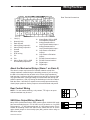
Rear Terminal Connections
1.
2.
3.
4.
5.
6.
7.
8.
9.
10.
11.
Line (L1)
Neutral (L2/N)
Earth Ground
Alarm (Relay) Output #1–
Alarm (Relay) Output #1+
Unused
Unused
RTD 3rd Leg
PVPV+
Alarm (Relay, SSR, or SSR
Drive Module) Output #2+
12.
13.
14.
15.
16.
17.
18.
19.
20.
Alarm (Relay, SSR, or SSR
Drive Module) Output #2Analog (Retransmission or
Loop Power #2 Module) Output +
Analog (Retransmission or
Loop Power #2 Module) Output Loop Power or Excitation
Output +
Loop Power or Excitation
Output RS-485 Communications +
RS-485 Communications Digital Input +
Digital Input -
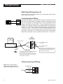
About the Mechanical Relays (Alarm 1 or Alarm 2)
The alarm 2 output may have an R-C snubber network to help filter
voltage transients created during the switching process. If you are using
the alarm 2 mechanical relay to switch a low current (high impedance)
load less than 1 milliamp, then this network may have to be removed. With
very light loads there is enough leakage current that will flow through the
snubber capacitors (~500 µA) leaving the load always in the ON condition.
Both the Alarm 1 and Alarm 2 outputs have normally-open and normallyclosed jumper positions. Set the jumper to select the desired relay action.
Rear Contact Wiring
20
NOTE: For rear contact switching, a dry contact, TTL logic or an opencollector transistor may be used.
19
SSR Drive Output Wiring (Alarm 2)
Many SSR’s (Solid State Relays) which switch typical 120/240 VAC loads
have two terminals that use ~3 to 30 VDC to turn the device on. Our SSR
Drive output is ~17 VDC when active and ~0.3 VDC when inactive. This is
suitable for switching most of the SSR’s on the market. Be sure to set the
option board jumper to the normally-open (NO) position when using an
SSR drive output.
330R User’s Manual
12
11
+
Input of
device
5
Wiring Practices
Wiring Practices
SSR Output Wiring (Alarm 2)
Be sure to set the option board jumper to the normally-open (NO) position
when using an SSR output.
Communications Wiring
12
11
+
Input of
device
A twisted shielded pair of wires should be used to interconnect the host
and field units. Belden #9414 foil shield and #8441 braid shield 22-gauge
wire are acceptable for most applications. The foil shielded wire has
superior noise rejection characteristics. The braid shielded wire has more
flexibility. Note that the maximum recommended length of the RS 485 line
is 4000 feet. Termination resistors are required at the host and the last
device on the line. Some RS 485 cards/converters already have a
terminating resistor. We recommend using an RS-232/RS-485 converter
(products no. 500-485). The communication protocol is asynchronous
bidirectional half-duplex, hence the leads are labeled "Data +" and "Data –
".
330
Terminals
PC
or other host
Twisted, shielded
Data +
RS-485
port
Data —
17
To "+" data terminal of
next device.
18
To "–" data terminal of
next device.
CAUTION
The shield needs to be connected continuously
but only tied to one ground at the host.
Failure to follow these proper wiring practices
could result in transmission errors and other
communications problems
Use a 60 to100 Ohm terminating resistor
connected to the two data terminals of
the final device on the line.
Thermocouple Input Wiring
Note: Refer to thermocouple
manufacturer's specification for
positive and negative color code.
(typically red)
PV1:
6
- LEAD
9
+ LEAD
10
330R User’s Manual
Wiring Practices
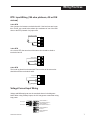
RTD Input Wiring (100 ohm platinum, JIS or DIN
curves)
2-wire RTD
Use a jumper wire between terminals 8 and 9. If the lead runs are longer
than 10 feet, use a small value resistor (the resistance of one of the lead
wires to the RTD) instead of a jumper wire.
jumper wire or resistor
8
9
RTD
10
3-wire RTD
On a 3-wire RTD, the two wires of the same color should be wired to
terminals 8 and 9.
3rd leg of RTD
8
RTD
9
RTD
10
4-wire RTD
The fourth leg should not be attached. The two wires of the same color
should be wired to terminals 8 and 9.
3rd leg of RTD
8
RTD
9
RTD
10
4th leg (open)
Voltage/Current Input Wiring
Voltage and Milliamp Inputs use the terminals shown in the diagrams
below. When using milliamp inputs, the 330 may power a transmitter using
loop power.
PV1 Input –
9
16
LOOP POWER or
EXCITATION OUTPUT –
PV1 Input +
10
15
LOOP POWER or
EXCITATION OUTPUT +
14
LOOP POWER #2
OUTPUT –
13
330R User’s Manual
LOOP POWER #2
OUTPUT +
7
Wiring Practices
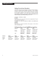
Voltage/Current Input Operation
Volt/milliamp inputs give you many range selections: 4-20 mA, 0-20 mA, 15V, 0-5V, +/- 30mV, 0-30mV, 0-60mV, or 0-100mV. This is software
selectable. When the input is within the selected input range, the proper
process variable is displayed. As the input falls out of range, a two stage
error message is displayed. The first stage flashes an estimated process
variable based on the out-of-range input. As the input falls further out of
range, the display stops flashing and displays -Hi- or-Lo-.
4 to 20mA, 1 to 5 Volt or +/- 30mV
Live Zero
These inputs are the most common choice for most applications. They are
typically used with transmitters.
0 to 20mA, 0 to 5 Volt, 0 to 30mV, 0 to 60mV, or 0 to 100mV (true
unipolar)
Dead Zero
These inputs are used with transmitters, strain gauges, or other devices
with a zero based output.
PV Display Values for each Volt/Milliamp Input Type
DISPLAY
“-Lo-”
“-Hi-”
INPUT
Current(4-20mA)
3.68 to 20.32
3.60 to 3.68
20.32 to 20.40
Below 3.60
Above 20.40
INPUT
Voltage(1-5V)
0.92 to 5.08
0.90 to 0.92
5.08 to 5.10
Below 0.90
Above 5.10
INPUT
Voltage(+/-30mV)
-31.20 to 31.20
-31.50 to -31.20
31.20 to 31.50
Below -31.50
Above 31.50
INPUT
Voltage(0-5V)
0 to 5.10
5.10 to 5.125
Above 5.125
INPUT
Voltage(0-30mV)
0 to 30.60
30.60 to 30.75
Above 30.75
INPUT
Voltage(0-60mV)
0 to 61.20
61.20 to 61.50
Above 61.50
INPUT
Voltage(0-100mV)
0 to 102.00
102.00 to 102.50
Above 102.50
Normal
Flashes
DISPLAY
Normal
Flashes
“-Hi-”
8
INPUT
Current(0-20mA)
0 to 20.40
20.40 to 20.50
Above 20.50
330R User’s Manual
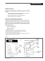
Hardware Set Up
Hardware Set Up
Hardware configuration determines the available outputs as well as output
relay status. The 330R Monitor comes from the factory set with the
following:
• All specified modules and options installed (for details, refer to the
Order Code in the first section of this manual).
• Process variable input set to accept a milliamp input.
• Alarm relay outputs set to normally open.
Accessing and Changing Jumpers
Depending on the model number ordered, the 330 will come with one or
two boards. the 330R000 is shipped with one board. The 330R with any
additional specified options will be shipped with two boards. The alarm
relay output jumper is set at the factory to normally open (N.O.). This
jumper, or in the case of units with two boards, are at the end of the boards
and are easy to access.
You will need this equipment:
Needle-nose pliers (optional)
Phillips screwdriver (#2)
Wrist ground strap
1. With power off, loosen the two front screws and remove them.
2. Slide the chassis out of the case by pulling firmly on the bezel.
3. Locate the jumper to change. See Figure 1.
4. Using the needle-nose pliers (or fingers), lift the jumper and place it in
the alternative position marked on the board.
Figure 1
330R User’s Manual
9
Configuration
Adding or Changing Option Boards or Output Modules
Module Representation
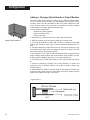
The basic 330R has provisions for adding up to 4 different option boards.
Three of these option boards may be shipped with different output
modules; these may also be added in the field. These modules are the
same as those used in the 535 Series of controllers. To add or change
output boards or modules, please do the following:
You will need this equipment:
Needle-nose pliers (optional)
Phillips screwdriver (#2)
Wrist ground strap
1. With power off, loosen the two front screws, and remove them.
2. Slide the chassis out of the case by pulling firmly on the bezel.
3. If unit has two boards, one main and one option, carefully pry the board
apart at the connector, (see Figure 2) until it separates approximately 1/2
inch.
4. Carefully detach the option board from the two fingers holding it to the
instrument bezel. Under most circumstances, there is no need to remove
the main board from the instrument bezel.
5. The available “A”, “B”, and “C” option board each have the provision for a
plug-in analog output module and second alarm output module (see the
ordering code for details.) See Figure 1 for module positioning.
6. The connector for the RS 485 module is on the option board. (see Figure
1.)
7. Remove modules by clipping the tie wrap holding it in place and
replacing it with a different module. Use a new tie wrap to secure the
module in place.
8. Reassemble the 330R by carefully lining up and pressing together the
connector pins between the main and option board, then snap the option
board to the fingers securing it to the bezel.
Figure Figure 2
10
330R User’s Manual
Display Modes
330 Display Modes, Menus and Security Levels
Normal Mode
Power Up
No
Security
Applied:
S.PAR
Security
Applied:
Menu Mode
S.CON
Security
Applied:
PV and
Alarm
Display
PArA
Menu
in
Menu
S.CAL
Security
Applied:
CAL
Menu
Security
Setup:
SEC
Menu
CuSt
Menu
out
Menu
ALAr
Menu
SEr
Menu
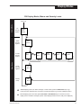
While displaying the PV, an alarm message or a menu label, press the UP & Down keys to go
to the next menu. Hold the keys one second or press them again to go to each subsequent menu.
While displaying the menu label, press ACK & UP or ACK & Down keys to exit the menu and
display the PV and alarm messages ("buSY" will be displayed until the PV is ready to be displayed).
330R User’s Manual
11
Configuration
Configuration (Menu Mode)
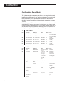
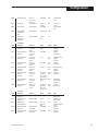
The 330 has settable parameters that allow you to customize the monitor
for a particular application. These parameters are changed when initially
installing the instrument or if your application changes. You should review
these parameters prior to operating the instrument for the first time.
Operating functions and alarms are described in greater detail on pages
17 to 23.
While displaying the PV, an alarm message or a menu label, press the UP
& DOWN keys to go to the next menu; hold the keys 1 sec. to go to each
subsequent menu. While displaying a menu label, press the ACK & UP or
ACK & DOWN keys to exit the menu and display the PV; then “buSY” will
be displayed temporarily. Press the up or down keys to modify a value.
1
“PArA” Menu
Label
PEAk
Description
PV peak (max) value
Appears if
Always appears
Values
-999 to 9999
VALY
PV valley (min) value
Always appears
-999 to 9999
AHi1
Alarm 1 high setpoint
AC-1 is High or HiLo
-999 to 9999
ALo1
Alarm 1 low setpoint
AC-1 is lo or HiLo
-999 to 9999
AHi2
Alarm 2 high setpoint
AC-2 is High or HiLo
-999 to 9999
ALo2
Alarm 2 low setpoint
AC-2 is lo or HiLo
-999 to 9999
2
“in” Menu
Label
InPt
Description
PV input
Appears if
Always appears
Default Notes
Curr
No jumpers
Type
PV input type
Always appears
dEg
PV degree units
or rtd
PV linearization
inPt is tc.uP, tc.dn
kELV
inPt is Curr
or Volt
Values
tc.uP,tc.dn, rtd,
Curr, VoLt
J tc, E tc, k tc,
b tc, n tc, r tc,
S tc, t tc, g tc,
C tc, PL.tc, din,
JiS, 4-20, 0-20
1-5, 0-5, +-.03,
0-.03, 0-.06,
0-.10
FAhr, CELS,
oFF, Sqrt, CuSt
oFF
CV multiplier (used
to calculate flow
PV from differential
pressure)
PV decimal point
Lin is Sqrt
oFF or 0.1
to 999.9
oFF
inPt is rtd,
Curr or VoLt
inPt is Curr
nnnn, nnn.n,
nn.nn, n.nnn
-999 to 9999
nnnn
Lin
CV
dP
PVLo
12
PV low input value
or VoLt and Lin
is not CuSt
Default Notes
-999
Press UP & DOWN to
reset; uses dP dec. pt.
9999
Press UP & DOWN to
reset; uses dP dec. pt.
0
Uses dP
decimal point
0
Uses dP
decimal point
0
Uses dP
decimal point
0
Uses dP
decimal point
4-20
Selections for
thermocouple
rtd, Curr or volt
are available
according to the
value of inPt
FAhr
0
Selections for
square or custom
linearization are
available.
Flow PV formula:
CV* (PV input)
rtd allows nnnn
or nnn.n only
Uses dP decimal
point
330R User’s Manual
Configuration
PVHi
PV high input value
FiLt
PV input filter
inPt is Curr
or VoLt and Lin
is not CuSt
Always appears
OfSt
PV input offset
gAin
PV gain applied
using PV input
range
Rear contact
(digital input)
configuration.
rcon
3
Label
in-1
“CuSt” Menu
Description
Custom linearization
input point 1
PV-1
Custom linearization
PV point 1
in-2
Custom linearization
input point 2
PV-2
Custom linearization
PV point 2
in-n
Custom linearization
input point n
(n=3 to 14)
Custom linearization
PV point n
(n=3 to 14)
PV-n
in15
Custom linearization
input point 15
PV15
Custom linearization
PV point 15
4
Label
rLY1
“out” Menu
Description
1st alarm output
relay action
2nd alarm output
relay action
Retransmission
output assignment
rLY2
rEtr
rELo
rEHi
Retransmission low
range value
Retransmission high
range value
330R User’s Manual
-999 to 9999
1000
Uses dP decimal
point
oFF
Always appears
oFF or 0.1
to 120.0
-999 to 9999
In tenths of a
second
Uses dP decimal
point
Always appears
0.100 to 9.999 1.000
Option is installed
Ack, rSt,
Lock
Appears if
inPt is Curr or
VoLt and Lin
is CuSt
inPt is Curr or
VoLt and Lin
is CuSt
inPt is Curr or
VoLt and Lin
is CuSt
inPt is Curr or
VoLt and Lin
is CuSt
inPt is Curr or
VoLt and Lin
is CuSt
inPt is Curr or
Volt and Lin
is CuSt
Values
Default
Minimum input 4.00
value
inPt is Curr or
VoLt and Lin
is CuSt
inPt is Curr or
VoLt and Lin
is CuSt
0
Ack
-999 to 9999
0
>= in-1
in-1
value
-999 to 9999
PV-1
value
>= in-(n-1)
in-(n-1)
value
If PV-2<PV-1 PV-(n-1)
then PV-n<=
value
PV-(n-1); else
PV-n>=PV-(n-1)
Maximum input 20.00
value
If PV-2<PV-1
then PV15<=
PV14; else
PV15>=PV14
PV14
value
Appears if
Always appears
Values
oFF, on
Default
on
Option is installed
oFF, on
on
Option is installed
oFF, 4-20,
20-4, 0-20,
20-0
-999 to 9999
oFF
-999 to 9999
1000
rEtr is 4-20, 20-4,
0-20 or 20-0
rEtr is 4-20, 20-4,
0-20 or 20-0
0
Notes
Dependent on inPt
and typE
selections
Uses dP
decimal point
Dependent on inPt
and typE
selections
Uses dP
decimal point
Dependent on inPt
and typE
selections
Uses dP
decimal point
Dependent on
input and typE
selections
Uses dP
decimal point
Notes
Selects on/off if
alarm 1 active
Selects on/off if
alarm 2 active
Selects
retransmission(mA)
output
Uses dP
decimal pt.
Uses dP r
decimal pt.
13
Configuration
5
Label
AC-1
“ALAr” Menu
Description
Alarm 1 type
Aou1
Lch1
Ack1
Alarm 1 output
Alarm 1 latching
Alarm 1
acknowledgement
Alarm 1 deadband
AC-1 is not oFF
AC-1 is not oFF
AC-1 is not oFF
Values
Default
oFF, High, Lo, oFF
HiLo
nonE,rLY1,rLY2 rLY1
oFF, on
on
oFF, on
on
AC-1 is not oFF
1 to 9999
Alarm 1
power-up state
Alarm 2 type
AC-1 is not oFF
PV, AL, noAL
Always appears
Alarm 2 output
Alarm 2 latching
Alarm 2
acknowledgement
Alarm 2 deadband
AC-2 is not oFF
AC-2 is not oFF
AC-2 is not oFF
oFF, High, Lo, oFF
HiLo
nonE,rLY1,rLY2 rLY2
oFF, on
on
oFF, on
on
AC-2 is not oFF
1 to 9999
2
Uses dP
decimal pt.
APu2
Alarm 2
power-up state
AC-2 is not oFF
PV, AL, noAL
PV
6
Label
StAt
“SEr” Menu
Description
RS-485 station
address
RS-485 baud rate
selection
Appears if
Comm. board
is installed
Comm. board
is installed
Values
0 to 99
Default
0
9600
RS-485 CRC-16
selection
Comm. board
is installed
1200, 2400,
4800, 9600,
19.2k
oFF, on
Adb1
APu1
AC-2
Aou2
Lch2
Ack2
Adb2
BAud
Crc
Appears if
Always appears
Notes
2
Uses dP
decimal pt.
PV
Notes
on
7
“CAL” Menu
To execute a calibration step, press the UP and DOWN keys simultaneously while the value is displayed. To skip a
calibration step, press the ACK key. The parameters are:
14
Label
Description
Appears if
Display Values
Default
PVLC
Calibrates
PV low input
Always appears
0.000
0.000
(V, mV, mA
or ohms)
PVHC
Calibrates
PV high input
PVLC calibration
was just
completed
Value can be
adjusted using
the UP and
DOWN Keys
3.634V, 87.66V,
45.99mV,
18.07mV,
19.20mA,
300.0 Ohms,
or 150.0 ohms
Calibration
Procedure
Short PV+
(and 3rd leg
if PV is an rtd)
to PV-, then
press the UP and
DOWN keys
simultaneously
Apply the
displayed V, mV,
mA or ohms value to
PV (and short
the 3rd leg input
to PV-ifPV is
an rtd), then
press the UP and
DOWN keys
simultaneously
330R User’s Manual
Configuration
CJLo
Calibrates
cold junction
sensor low
input
inPt is
tc.uP or tc.dn
0.000
0.000 (V)
CJHi
Calibrates
cold junction
sensor high
input
CJLo calibration
was just
completed
Value can be
adjusted using
the UP and
DOWN keys
0.898V
tc.in
Calibrates
inPt is
cold junction tc.uP or tc.dn
compensation
for t/c inputs
Default value
680F, 360C or
633k
out0
Calibrates the rEtr is 0-20
retrans. 0mA or 20-0
output
0.000
0.000 (mA)
out4
Calibrates the rEtr is 4-20
retrans. 4mA or 20-4
output
4.000
4.000 (mA)
330R User’s Manual
Short PV+
to PV-, then
press the UP and
DOWN keys
simultaneously
Apply the
indicated
voltage to PV,
then press the UP
and DOWN keys
simultaneously
Apply t/c calibrator
to PV using the
correct t/c wire
type and the
displayed temp.
setting, then press
the UP and
DOWN keys
simultaneously
Attach mA meter
to mA output and:
1) press the UP
or DOWN key to
adjust the display
to match the meter
reading; 2) press
the UP and
DOWN keys
simultaneously;
3) repeat steps (1)
and (2) until the
displayed OmA
output value is
within tolerance
Attach mA meter
to mA output and:
1) press the UP
or DOWN key to
adjust the display
to match the meter
reading; 2) press
the UP and
DOWN keys
simultaneously;
3) repeat steps (1)
and (2) until the
displayed 4mA
output value is
within tolerance
15
Configuration
ou20
Calibrates the rEtr is 4-20,
retrans. 20mA 20-4, 0-20 or
output
20-0
8
Label
CodE
“SEC” Menu
Description
Security code
which enables
security override for
1 minute
PARA menu
security
enable/disable
CONF menu
security
enable/disable
CAL menu
security
enable/disable
S.PAr
S.Con
S.CAL
16
20.00
20.00 (mA)
Appears if
Always appears
Values
-999 to 9999
Default
0
Always appears
oFF, on
oFF
Always appears
oFF, on
oFF
Always appears
oFF, on
oFF
Attach mA meter
to mA output and:
1) press the UP
or DOWN key to
adjust the display
to match the meter
reading; 2) press
the UP and
DOWN keys
simultaneously;
3) repeat steps (1)
and (2) until the
displayed 20mA
output value is
within tolerance
Notes
330R User’s Manual
Operation
OPERATION
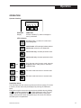
Operator Interface
ACK
FEATURE
Display
FUNCTION
Process variable (PV), alarm messages or
menu parameters
LED Indicators:
ON when Alarm 1 or Alarm 2 is active and
acknowledgeable
ACK
ACK
normal mode: ACKnowledge (release) alarms
menu mode: select the next parameter
menu mode only: increase parameter value
menu mode only: decrease parameter value
and
ACK
and
ACK
and
Go to the next menu in menu mode, reset the
displayed peak or valley value, or execute a
calibration step
Exit menu mode and return to normal mode
Exit menu mode and return to normal mode
Peak/Valley Values
The 330 stores both the maximum (peak) and minimum (valley) PV values
in memory. These values may be displayed by entering the Parameter
Menu.
Each value may be reset to the current process variable value by holding
the key and then pressing the key while viewing the value. The rear
contact can be configured to reset the peak/valley values. Closing the
contact will reset both values simultaneously to the current PV value as
selected by the rcon parameter.
330R User’s Manual
17
Operation
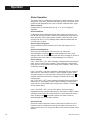
Alarm Operation
The alarms may be configured for latching type, latching sequence, output
assignment, relay state, deadband and power up state. Placement of the
trip points and dead bands can create a number of different alarm types.
Alarm Indication
A tripped alarm is indicated when the “AL 1” or “AL 2” message is
displayed.
Alarm Dead Band
Configurable alarm dead bands prevent alarm relays from fluttering on
and off after entering an alarm condition and settling back down near the
alarm set points. After entering alarm condition, alarm relay will not deenergize until PV, PV, or PV2 reading falls an additional dead band unit
from the alarm set point.
Alarm Output Assignment
Selects whether the alarm activates one of the relay outputs (rLY1 or
rLY2).
Alarm Acknowledgement
Alarms are acknowledgeable if the ACK key is lit. Alarms are
acknowledged by pressing . When acknowledged, the alarm relay
changes state to its normal condition and the alarm message is cleared. If
both alarms are active, Alarm 1 is acknowledged prior to Alarm 2.
Alarm Latching
Latch = OFF, ACK = ON: Alarm message is displayed and relay changes
state when PV enters alarm condition. Alarm message is cleared and
relay returns to normal state when leaving alarm condition. Alarm can be
released by pressing
.
ACK
ACK
Latch = ON, ACK = ON: Alarm message is displayed and relay changes
state when PV enters alarm condition. Alarm message remains active
and relay remains in current state after leaving alarm condition until
is
pressed at which point the alarm message is cleared and the relay
changes state.
atch = OFF, ACK = OFF: Alarm message is displayed and relay changes
state when PV enters alarm condition. Alarm message is cleared and
relay returns to normal state when leaving alarm condition. Pressing
will not release alarm.
ACK
ACK
Latch = ON, ACK = OFF: Acts as a limit device. Alarm message is
displayed and relay changes state when PV enters alarm condition. Alarm
message remains active and relay remains in current state after leaving
alarm condition until
is pressed. However, the alarm cannot be
acknowledged while in the alarm condition.
ACK
Alarm Power Up
Defines the state of the alarm when the instrument is powered up. The
instrument can be configured to never go into alarm upon power up, to
always go into alarm or to only go into alarm if the process variable values
warrant.
18
330R User’s Manual
Operation
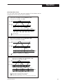
Alarm Operation Charts
The five charts that follow represent samples of how alarms can be
configured to work. You may set yours up similarly.
Alarm control is set at HiLo, Latch set at ON, ACK set at OFF,
Output set at rLY1 and Relay 1 set at OFF.
AHi
AHi – Adb
ALo + Adb
ALo
PV
OFF
OFF
OFF
OFF
OFF
OFF
ON
ON
ON
ON
ON
ON
1
2
1
2
1
2
Relay 1
Alarm Message
ACK Key
1 = Cannot be cleared
2 = Relay can be turned on and Alarm message off by ACK key
Alarm control is set at HiLo, Latch set at OFF, ACK set at OFF,
Output set at rLY2 and Relay 2 set at ON.
AHi
AHi – Adb
ALo + Adb
ALo
PV
ON
OFF
ON
ON
OFF
ON
OFF
OFF
ON
OFF
ON
OFF
1
1
1
Relay 2
Alarm Message
ACK Key
1 = Relay and Alarm message cannot be ACK (acknowledged).
Alarm control is set at HiLo, Latch set at ON, ACK set at ON,
Output set at rLY1 and Relay 1 set at ON.
AHi
AHi – Adb
ALo + Adb
ALo
PV
ON
2
ON
2
ON
2
ON
2
ON
2
ON
2
1
2
1
2
1
2
Relay 1
Alarm Message
ACK Key
1 = Relay and Alarm message can be turned off by ACK key.
2 = Relay and Alarm message will be on due to latching
function unless previously cleared; if it is on, it can be cleared by pressing ACK key.
330R User’s Manual
19
Operation
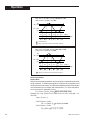
Alarm control is set at HiLo, Latch set at ON, ACK set at OFF,
Output set at rLY1 and Relay 1 set at OFF.
AHi
AHi – Adb
ALo + Adb
ALo
PV
OFF
OFF
OFF
OFF
OFF
OFF
ON
ON
ON
ON
ON
ON
1
2
1
2
1
2
Relay 1
Alarm Message
ACK Key
1 = Cannot be cleared.
2 = Relay can be turned on and Alarm message off by ACK key.
Alarm control is set at HiLo, Latch set at OFF, ACK set at ON,
Output set at rLY2 and Relay 2 set at ON.
AHi
AHi – Adb
ALo + Adb
ALo
PV
OFF
OFF
OFF
OFF
OFF
OFF
ON
ON
ON
ON
ON
ON
1
2
1
2
1
2
Relay 2
Alarm Message
ACK Key
1 = ACK key or contact will turn relay and Alarm message off.
Input Linearization
Square Root
Many flow transmitters generate a non-linear signal corresponding to the flow
being measured. To linearize this signal for use by the 330, the square root of
the signal must be calculated. The 330 has the capability to perform this square
root linearization prior to display and retransmission. To utilize this feature,
you must set the Lin parameter to Sqrt.
PV = PVLo + [(PVHi - PVLo) (input - low) / (high - low)]
Example: Lin = Sqrt, Cv=Off, PVHi = 5000, PVLo = 0, inPt = Volt, typE = 1-5,
dP=nnnn
(high = 5, low = 1)
If the PV input = 2 Volts,
PV = 0 + (5000 - 0) (2 - 1)/ (5 - 1) = 2500
If the PV input = 3 Volts,
PV = (5000 - 0) (3 -1) / (5 - 1) = 3535.
20
330R User’s Manual
Operation
Square Root and CV (Flow Coefficient)
The 330 can measure flow rate through a valve or other constriction using
a differential pressure transducer input, square root linearization, and the
valve’s CV (flow coefficient) value at a given valve position. For materials
with a specific gravity of 1 (i.e. water), flow is measured using the following
formula:
PV = CV (PVHi -PVLo)(input-low)/(high-low) + PVLo
Example: inPt = Curr, tYPE = 4-20, Lin = Sqrt, CV = 50.0, PVHi =30.0,
PVLo = 0.0, dP=nnn.n (high = 20mA, low = 4mA)
If the PV input = 5mA,
PV = 50.0 (30.0-0.0)(5-4)/(20-4) + 0.0 = 68.5
If the PV input = 8mA,
PV = 50.0 (30.0-0.0)(8-4)/(20-4) + 0.0 = 136.9
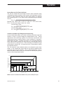
Custom Linearization (PV Voltage/current input only)
Custom Linearization allows you to take virtually any nonlinear signal and
linearize it using a 15-point straight line approximation curve. Typical
applications are linearizing signals from nonlinear transducers and
displaying/controlling volume based on level readings for irregularlyshaped tanks and bins. To define the function, you must enter data point
pairs. Each of these consists of an input value (in-1 through dEg5) and an
output value (PV-1 through PV15). Each data point pair defines a single
point along the function line. You may enter up to 15 point-pairs to define
the nonlinear function.
The 330 treats the region between points as a straight line (see figure
below). It can calculate the output value for any input by finding the two
points the input value lies between. This is called interpolation. Since it
takes two points to define a line, you must enter at least two point pairs to
use the custom linearization feature.
Output Value (in engineering units)
PV-10
PV-9
PV-8
PV-7
PV-6
PV-5
PV-4
PV-3
Actual Function
Linear Approximation
PV-2
PV-1
in-1 =
in-2
in-3
in-4
in-5
in-6
or 1.000
in-7
in-8
in-9
in-10 =
5.000
0.000
Input Value (in volts)
Note: Custom Linearization is available for any volt or milliamp PV input.
330R User’s Manual
21
Security
Security
If security is applied to a menu (using the S.PAr, S.Con or S.CAL
parameter in the SEC menu) then that menu cannot be accessed until the
correct security code is entered.
For example, if security is applied to a particular menu and both the UP
and DOWN keys are pressed to access that menu, “CodE” will be
displayed for 2 seconds. Then “0” will be displayed. This value must be
modified (using the UP and DOWN keys) to match the “CodE” value
previously selected in the SEC menu.
Then after 2 seconds of key inactivity the security code value will be
checked. If an erroneous security code value is entered, the menu will not
be displayed (the PV value will be displayed instead).
If 6264 is entered, then all security parameters will be set to default values
(thus turning security off) and the menu will be displayed.
If the correct security code is entered (rather than 6264), security will be
temporarily disabled and the menu will be displayed. After 60 seconds of
key inactivity, security will be re-armed. (In other words, if no keys are
pressed for 60 seconds, the security code will need to be re-entered
before the menu can be accessed again).
22
330R User’s Manual
Trouble Shooting
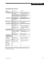
Troubleshooting / Service
Symptom
THERMOCOUPLE
“-in-” Readout
Wrong Readout
RTD
“-in-” readout
Wrong Readout
VOLTAGE/CURRENT
“-Hi-” or “-Lo-”
Possible Cause
Solution
Wrong thermocouple
type configured.
Wrong input terminals used.
Extension wire used is not
compatible with thermocouple.
Defective thermocouple.
Reverse polarity.
Wrong thermocouple
configured in input
configuration.
Check input configuration
for proper thermocouple type.
Check input wiring.
Match extension wire with
thermocouple wire.
Replace thermocouple.
Check input wiring.
Configure correct input type.
Wrong input terminals used.
Defective RTD.
Wrong RTD configured in
input configuration.
Lead impedance exceeds
specification
(100 ohms per lead max).
Leads must have equal
resistance.
Check input wiring.
Replace RTD.
Configure correct input type.
Wrong input terminals used.
Voltage or mA input level
exceeds or does not meet
specification.
Defective transmitter.
Reverse polarity.
Check input wiring.
Recalibrate transmitter output to
meet specifications.
Wrong Readout
ERROR-MESSAGES
“E.DAT” or “E.A2D”
Readout
Initialization error.
“E.CHE” Readout
Checksum error during
power up.
Instrument resets,
Electrical noise problem
erratic PV reading
beyond the filtering
memory loss,
capability of the monitor.
reversion to
defaults,or failure
to detect output
signal change.
Place unit closer to RTD or
resistance. Use RTD transmitter
when distance between RTD
and controller is greater than
1000 feet.
Replace transmitter.
Check input wiring.
Call factory for assistance.
Call factory for assistance.
Refer to following section on
Electrical Noise Solutions.
Note: If after checking the solution you still experience difficulty with your
unit, please contact either your Moore Industries representative or one of
our application engineers.
330R User’s Manual
23
Specifications
Electrical Noise Solution
Contact/Load Suppression:
When the instrument relays are used to switch another relay coil,
contactor, solenoid or some other inductive load, large voltage spikes are
created back on the AC power line. When excessive, these voltage spikes
can disrupt the operation of this product, causing it to reset as if power had
just been applied. These types of loads should have suppression devices
right across the load, at the load. We recommend the use of an R-C
snubber. Additionally, an MOV should be placed across loads greater than
0.25 amps.
When a relay opens an inductive load, there is energy that will form around
the contacts. This is a form of electrical noise that could disrupt the
product if severe enough and damage the relay contacts as well. Internal
to the product is an R-C snubber across each relay contact to help absorb
some of this energy. An additional snubber mounted to the terminal block
may improve contact life and reliability when switching large inductive
loads.
Specifications
Accuracy
All accuracy ratings are at reference conditions (at least 30 min. at 25 °C)
Thermocouple Inputs:
± 0.15% of span typical ± 1 digit
RTD Inputs:
± 0.10% of span typical ± 1 digit
Millivolt/Voltage/Current Inputs:
± 0.05% typical ± 1 digit
Resolution:
0.004% of span typical
Architecture
The 330 hardware can be configured as follows:
Inputs:
One universal process variable input is standard.
Available options include digital input.
Outputs:
Up to 3 outputs are available, plus transmitter loop power or
stain gauge excitation voltage.
RS-485 Communications: Available as an option.
Process Variable Input
Universal input. Any input type may be selected in the field via the front
panel or communications.
Thermocouples
B
E
J
K
N
R
S
Range °F
104 to 3301
-454 to 1832
-346 to 1832
-418 to 2500
-328 to 2372
32 to 3182
32 to 3182
Range °C
40 to 1816
-270 to 1000
-210 to 1000
-250 to 1371
-200 to 1300
0 to 1750
0 to 1750
Specifications and information subject to change without notice.
24
330R User’s Manual
Specifications
T
W (G)
W5 (C)
Platinel II
RTD's
100 ohm Pt. (DIN)
100 ohm Pt. (JIS)
-328 to 752
32 to 4172
32 to 4172
-148 to 2550
Range °F
-328 to 1562
-328.0 to 545.0
-328 to 1202
-200 to 400
0 to 2300
0 to 2300
-100 to 1399
Range °C
-200 to 850
-200.0 to 285.0
-200 to 650
-328.0 to 545.0
-200.0 to 285.0
Current, Voltage, or Millivolt Signals
Milliamps DC
Volts DC
Millivolts DC
4 to 20, 0 to 20
1 to 5, 0 to 5
-30 to 30, 0 to 30, 0 to 60, 0 to 100
Input Signal Failure Protection
Thermocouple inputs are configurable for upscale or downscale
burnout; RTD inputs fail upscale if any leg is broken.
Input Impedance
Current Input:
Voltage Input:
RTD or
Thermocouple Input:
Millivolt Input:
100 ohms
10 Mohms typical
100 Mohms typical
100 Mohms typical
Input Filter
A single pole lowpass filter with selectable time constants from 0.0
to 120.0 seconds is available.
Input Linearization
Square root linearization is available. Each thermocouple or RTD
input is automatically linearized. The PV input may use 15 point
user-definable linearization if it is a voltage, millivolt or milliamp
input.
Contact Input
External dry contact input or open-collector transistor input for
alarm acknowledgement, peak/valley reset or keypad lockout.
Isolated from process variable input and digital circuitry.
Memory
Non-volatile EEPROM.
330R User’s Manual
25
Specifications
Transmitter Loop Power or Excitation Voltage
Loop power capacity is 40mA at 24VDC. Excitation voltage is
10VDC ± 2% into at least 175 ohms.
Sampling Rate
Input sampled 12 times per second (every 83.3 msec).
Digital Displays
Green LED display is 4-digit, 7 segment, 0.56” (14.3mm) high.
Range is -999 to 9999. Assignable decimal position with current,
voltage, or millivolt inputs.
Mounting
Panel-mounted with a depth of 6.14 inch (156 mm).
Wiring Connections
Screw terminals on the rear of case.
Power Consumption
24 VA maximum.
Weight
Approx. 1.0 lbs (0.45 kg).
Ambient Temperature
Operative Limits:
Storage:
32 to 122 °F (0 to 50°C)
-40 to 185 °F (40 to 85°C)
Relative Humidity
10 to 90% at 40°C (104°F), non-condensing.
Analog Retransmission Output
Either 0-20mA, 4-20mA, 20-4mA or 20-0mA(front panel
selectable) into a load up to 1000 ohms.
Accuracy ± 20µ A @25 °C.
Mechanical relays
SPDT electromechanical relay. Resistive load rated at 5 amps at
120/240 VAC. Normally open or normally closed selection is made
by jumper.
Solid state relay (triac) module
Resistive load rated at 1 amp at 120/240 VAC.
DC logic (SSR drive) module
“ON” voltage is 17 Vdc (nominal). “OFF” voltage is less than
0.5 Vdc. (Current limited to 40mA.)
26
330R User’s Manual
Specifications
Voltage
90 to 250 VAC
Frequency
50/60 ± 2 Hz
Serial Communications
Isolated, bidirectional, two wire, half-duplex RS-485 serial
interface.
1,200 to 19,200 baud rate. Selectable CRC data
checking. Protocol
allows access to every operation
and configuration parameter.
Construction
Case:
Bezel:
Keys:
NEMA Rating:
Polylac PA-765 ABS, 94V-0 Rated
GE LEXAN® 500, 94V-0 Rated
Silicone rubber with diffusion printed
graphics
Front panel rated NEMA 4X when
instrument is properly installed
Security
Two levels of access are available: restricted and full.
A user-configurable code is used to enter the full access level.
Calibration
Comes fully calibrated from the factory. Field calibration can be
easily performed in the field with a precision multimeter and input
simulator. Process variable offset and gain factors are provided to
correct for sensor errors.
330R User’s Manual
27
28
330R User’s Manual
RETURN PROCEDURES
To return equipment to Moore Industries for repair, follow these four steps:
1. Call Moore Industries and request a Returned Material Authorization (RMA) number.
Warranty Repair –
If you are unsure if your unit is still under warranty, we can use the unit’s serial number
to verify the warranty status for you over the phone. Be sure to include the RMA
number on all documentation.
Non-Warranty Repair –
If your unit is out of warranty, be prepared to give us a Purchase Order number when
you call. In most cases, we will be able to quote you the repair costs at that time.
The repair price you are quoted will be a “Not To Exceed” price, which means that the
actual repair costs may be less than the quote. Be sure to include the RMA number on
all documentation.
2. Provide us with the following documentation:
a) A note listing the symptoms that indicate the unit needs repair
b) Complete shipping information for return of the equipment after repair
c) The name and phone number of the person to contact if questions arise at the factory
3. Use sufficient packing material and carefully pack the equipment in a sturdy shipping
container.
4. Ship the equipment to the Moore Industries location nearest you.
The returned equipment will be inspected and tested at the factory. A Moore Industries
representative will contact the person designated on your documentation if more information is
needed. The repaired equipment, or its replacement, will be returned to you in accordance with
the shipping instructions furnished in your documentation.
WARRANTY DISCLAIMER
THE COMPANY MAKES NO EXPRESS, IMPLIED OR STATUTORY WARRANTIES (INCLUDING ANY WARRANTY OF MERCHANTABILITY OR OF FITNESS
FOR A PARTICULAR PURPOSE) WITH RESPECT TO ANY GOODS OR SERVICES SOLD BY THE COMPANY. THE COMPANY DISCLAIMS ALL WARRANTIES ARISING FROM ANY COURSE OF DEALING OR TRADE USAGE, AND
ANY BUYER OF GOODS OR SERVICES FROM THE COMPANY ACKNOWLEDGES THAT THERE ARE NO WARRANTIES IMPLIED BY CUSTOM OR
USAGE IN THE TRADE OF THE BUYER AND OF THE COMPANY, AND THAT
ANY PRIOR DEALINGS OF THE BUYER WITH THE COMPANY DO NOT IMPLY THAT THE COMPANY WARRANTS THE GOODS OR SERVICES IN ANY
WAY.
ANY BUYER OF GOODS OR SERVICES FROM THE COMPANY AGREES
WITH THE COMPANY THAT THE SOLE AND EXCLUSIVE REMEDIES FOR
BREACH OF ANY WARRANTY CONCERNING THE GOODS OR SERVICES
SHALL BE FOR THE COMPANY, AT ITS OPTION, TO REPAIR OR REPLACE
THE GOODS OR SERVICES OR REFUND THE PURCHASE PRICE. THE
COMPANY SHALL IN NO EVENT BE LIABLE FOR ANY CONSEQUENTIAL OR
INCIDENTAL DAMAGES EVEN IF THE COMPANY FAILS IN ANY ATTEMPT
TO REMEDY DEFECTS IN THE GOODS OR SERVICES , BUT IN SUCH CASE
THE BUYER SHALL BE ENTITLED TO NO MORE THAN A REFUND OF ALL
MONIES PAID TO THE COMPANY BY THE BUYER FOR PURCHASE OF THE
GOODS OR SERVICES.
ANY CAUSE OF ACTION FOR BREACH OF ANY WARRANTY BY THE
COMPANY SHALL BE BARRED UNLESS THE COMPANY RECEIVES
FROM THE BUYER A WRITTEN NOTICE OF THE ALLEGED DEFECT OR
BREACH WITHIN TEN DAYS FROM THE EARLIEST DATE ON WHICH THE
BUYER COULD REASONABLY HAVE DISCOVERED THE ALLEGED DEFECT OR BREACH, AND NO ACTION FOR THE BREACH OF ANY WARRANTY SHALL BE COMMENCED BY THE BUYER ANY LATER THAN
TWELVE MONTHS FROM THE EARLIEST DATE ON WHICH THE BUYER
COULD REASONABLY HAVE DISCOVERED THE ALLEGED DEFECT OR
BREACH.
RETURN POLICY
For a period of thirty-six (36) months from the date of shipment, and under
normal conditions of use and service, Moore Industries ("The Company") will
at its option replace, repair or refund the purchase price for any of its manufactured products found, upon return to the Company (transportation charges
prepaid and otherwise in accordance with the return procedures established
by The Company), to be defective in material or workmanship. This policy
extends to the original Buyer only and not to Buyer's customers or the users
of Buyer's products, unless Buyer is an engineering contractor in which case
the policy shall extend to Buyer's immediate customer only. This policy shall
not apply if the product has been subject to alteration, misuse, accident, neglect or improper application, installation, or operation. THE COMPANY
SHALL IN NO EVENT BE LIABLE FOR ANY INCIDENTAL OR CONSEQUENTIAL DAMAGES.
United States • [email protected]
Tel: (818) 894-7111 • FAX: (818) 891-2816
Australia • [email protected]
Tel: (02) 8536-7200 • FAX: (02) 9525-7296
© 2005 Moore Industries-International, Inc.
Belgium • [email protected]
Tel: 03/448.10.18 • FAX: 03/440.17.97
The Netherlands • [email protected]
Tel: (0)344-617971 • FAX: (0)344-615920
China • [email protected]
Tel: 86-21-62491499 • FAX: 86-21-62490635
United Kingdom • [email protected]
Tel: 01293 514488 • FAX: 01293 536852
Specifications and Information subject to change without notice.