1
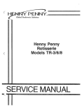
Integrated ‘Bot Controller (IBC) User Manual
Revision v0.1 – May 2003
www.robowars.org
As they say in all the product manuals, “Congratulations on your purchase of the Integrated Bot Controller from
RoboWars”. We hope you like it. We designed it for our own use first, and then decided to offer it for sale, so you
can be assured we engineered it to be the best possible controller for its intended application.
The IBC is designed to convert the servo-motor control signal from standard hobby radio control receivers into a
high-current PWM drive suitable for controlling the speed and power of small permanent magnet brush motors.
It’s on board microprocessor includes failsafe and auxiliary-relay control functions, and the wide-range switching
voltage regulator makes it able to operate off nearly any combination of batteries from 4v to 36v.
Connecting and using the IBC is very simple thanks to its integrated compact design.
3. R/C Servo
Input Leads
1. Motors
Left & Right
4. Auxiliary
Connector
(Optional)
2. Power Input
5. Option
Jumpers
(Layout below is rotated 180 degrees from above photo)
•
1 - Motor Drive Leads. – H1a/H1b and H2a/H2b.
These are the outputs that connect to your motors. The IBC is provided with short lengths of 12 gauge wire
pre-soldered to these points for you to attach to. We suggest securing all pre-attached wires to screw-down
ring-type terminal blocks that are mounted on the enclosure you use for the IBC. The main wires to your
motors can then be attached to the other side of the terminal blocks, making installation and removal simple
and reliable. H1a and H1b should be attached to the two power terminals of one sides drive motor, and H2a
and H2b should be attached to your other side motor. They are not polarized and can be attached either
way around. The correct orientation will vary depending on which side of the robot your motor is on and its
gear reduction method. The left and right motors are usually connected in opposite directions to each other.
If the motor runs backwards to the desired direction, reverse the connections to it. Multiple motors can be
attached in series or parallel provided the maximum combined voltages and currents do not overload the
controller.
•
2 – Power Input wires. – B+ and Ground.
These are the main power input to controller. Connect to your motor drive battery (after any isolation
switches). Power for both motors is drawn through these wires, so ensure a good connection is made to
allow high current flow. Short Lengths of 12 Gauge wire are pre-soldered to these points. Red is positive
and can be used with voltages from 4v to 36v. Black is negative and should be connected as directly as
possible to the batteries negative terminal. We do not recommend earthing via the Robots frame. The
power input is protected against accidental brief reverse-polarity connections with an on-board diode, but
please take care to get these the right way around.
•
3 – R/C servo Input Leads – Left, Right and Aux1
These 3-wire leads attach to your radio control receiver. They have standard connectors that will fit most
hobby radio control receivers. The connectors are wired to suit Futaba, JR and Hi-Tec receivers; if you have
an Airtronics or other brand radio receiver, please check its servo pin outs before connection. The brown wire
is Ground (-), the Red Wire is Positive (+V) and the Orange wire is Signal. If you intend to use the
controller’s on-board “Mixing” feature, make sure the left and right inputs are connected to the receiver
outputs that correspond to the X and Y axis of the single transmitter joystick you wish to use for driving. The
Aux input can be connected to any other desired receiver channel or left unused. Power can be supplied to
the receiver from the controller through these leads if the “BEC” jumper is connected (see below)
•
4. Auxiliary Connector – AUX1 OUT
rd
This connector provides the 3 channel (Aux1) trigger outputs which can be used to operate relays for
weapon control or other functions, as well as the FLIP input and low-current 5v and 12v supplies. Pin details
are as follows. Pin 1 is the end of the connector that is closest to the servo-input leads
#1 = +12v – This pin will provide a stable 12v output from the switch-mode regulator, regardless of
the battery input voltage. Do not attach devices that use more than 300ma. Small relays and
remote-power LED’s (with a suitable resistor) can be powered from here.
#2 = AUX High – An “Open Collector to Ground” output that will activate [internally connect to
ground (-)] when the “AUX1” Servo input Joystick is more than 30% “Forward”. This output can be
used to ground one side of a relay-coil to trigger weapons. The maximum current is 300ma. Use an
intermediate relay if you require more current than this.
#3 = AUX Low – The same as AUX High, but activates when the AUX1 input is more than 30%
“backwards”
#4 = +5v – This pin provides a regulated 5v output from the onboard 5v regulator, regardless of
battery voltage. Do not attach hi-current devices to this pin. Suitable for small relays or LED’s (with a
suitable resistor) only.
#5 = FLIP Input – an input that tells the controller to reverse its direction and steering controls if
the robot is turned upside down. This can either be connected to a tilt-switch that grounds the input
when the bot is inverted, or to either of the AUX High or Aux Low outputs for remote control of the flip
rd
function from the radio transmitter (if the 3 channel is not required for weapons). Do not exceed 5v
on this input. FLIP is active when grounded (0v).
#6 = Ground (Gnd) – Earth return point and ground reference for the Aux and FLIP inputs and
Outputs. This should be used for any auxiliary connections rather than relying on the main power
earth, since heavy current surges through the main cables can cause voltage fluctuations on the
main earth point.
•
5. Option Jumpers – DB, M, B and BEC.
These pins set the operation options for the IBC and can be either left “open” (jumper removed) or “closed”
(jumper connected) using the same sort of jumpers as used in personal computers. Their functions are as
follows.
DB = “DeadBand” – Closed = normal DeadBand, Open = wide DeadBand - This jumper alters the
“width” of the center-off area of the joystick inputs. If the center-play in your radio’s joysticks causes the
motors to move slightly even when the control joysticks are centred, then select the wide-DeadBand
option by removing the DB jumper. This will decrease the sensitivity of the robot to small stick
movements around the center position.
M = “Mix” – Closed = Mixing On, Open = Mixing Off (Tank steer). This jumper tells the controller to
combine (Mix) the left and right servo inputs so that a single joystick can be used to control both left and
right motors simultaneously. This style of control is much easier than the older “Tank Style” control,
where the left and right motors are controlled by separate joysticks, requiring two-handed operation. If
Tank-steering or transmitter-based mixing is desired, remove this jumper.
B = “Braking” – Closed = Braking on, Open = Braking off. This jumper causes the controller to apply
active current recirculation to the motors by connecting their outputs together when the joystick is
returned to the center position. This causes the robot to come to a halt much faster when the controls
are released and usually offers superior steering and control. If braking is not desired, remove this
jumper and the motors will “Coast” to a stop when the stick is centred.
BEC = “Battery Eliminator Circuit”. Closed = BEC On, Open = BEC Off. This connects the on-board
5v regulated power to the positive pin of the servo-attachment leads, which supplies power to your radio
receiver from the controller, “eliminating” the need for separate receiver battery. This prevents flatreceiver batteries and saves weight and space in small robots. Do not connect a battery to the receiver
AND turn on the BEC circuit since they may have different voltages. Do not use the BEC function if you
are also going to run Servo-motors from your receiver, since they use more current than the BEC can
supply.
•
6. Failsafe Function
The controller has an inbuilt failsafe function that will disable all outputs if no radio signal or an invalid radio
signal is received on the inputs. This is essential to pass safety inspections for combat robot events, not to
mention your own safety. Some older or cheaper radio controls however do not comply with the standard
servo-control specification, and may produce an over-range signal at maximum joystick-travel. This can
cause false failsafe triggering, and is apparent when the ‘bot works normally at part throttle, but suddenly
stops when the stick nears or reaches full travel. Most radio’s have adjustable “Travel”, “Span” “ATV” or
“Endpoint” settings to correct this. If yours does not, then either install joystick travel-limiting stops on your
radio transmitter or take your radio to a hobby-shop for adjustment to the correct maximum travel (1uS-2uS
signal)
•
7. Current Capacity
The IBC uses IRF1405 Mosfets that are theoretically rated for over 75 Amps of continuous current. In
practice however, this is limited by the ability of the FET’s to dispose of heat. The IBC’s solid-mass
heatsinks allow the FET’s to handle large surges of current without damage, but the continuous power rating
will vary according to the cooling airflow available to the heatsink. For maximum current handling
applications, a fan should be provided to ensure sufficient cooling, but this should not be required for the
typical application of this controller (12Kg or lighter robots). For comparison purposes, other controller
manufacturers rate un-heatsinked, fan-cooled FETS at 40 amps, and 50 Amps for heatsinked, fan-cooled
FET’s. If in doubt of your motors average power use, check the heatsink temperature after use. If it is
uncomfortably hot to touch, a fan is recommended.
•
8. Disclaimer
The IBC controller has been designed for experimental use in hobby-robots. Its performance is not guaranteed for any particular application.
Responsibility for determining its suitability for a motor or robot lies solely with the end-user. Use of this controller is at the owner’s risk. It must not
be used in any situation where its failure may cause a health or life-threatening situation. It should be understood that use in any combat robot will
subject the controller to unknown conditions (overloads, short circuits, misuse, shocks, vibration and physical damage) beyond the designer’s
control, and hence any failure of the controller that is determined by Robowars to be due to such external factors, and not a result of a production
fault or defect will not be covered under any express or implied warrantee. Repair, replacement and shipping of controllers deemed to be damaged
in this way will be entirely at the owners’ expense.
Combat Robots are dangerous. *You* are responsible for all actions performed by your robot, whether it is under your control or not.
•
•
9. Specifications and Features
•
Two x 50 Amp capable Heatsinked MOSFET Motor Drive Channels
•
TWO x Auxiliary Open-Collector Relay Outputs for weapon control – 300mA Drive Current each
•
FLIP input that reverses the steering controls if your bot is inverted – Switch to ground to activate
•
LOW VOLTAGE switching regulator - runs off any voltage from 4v - 36v
•
Built-in FAILSAFE function. Pass any Radio control safety test first time. 1uS – 2uS valid range
•
Built in MIX Function. No more Tank-Steering. One joystick drives AND turns
•
Built in BRAKE function. Precise steering control using active current-recirculation-techniques.
•
Built in BATTERY ELIMINATOR Circuit. – Powers your radio receiver automatically from the IBC. 5V output
•
REVERSE POLARITY PROTECTED. Inline diode protects the circuitry from expensive mistakes.
•
BATTLE PROVEN DESIGN. OSMC-based Mosfet drive circuitry and Software code
•
AUSTRALIAN DESIGNED AND MADE - Maximum value for money
•
FULLY OPEN SOURCE - No "Secret" circuit diagrams or "confidential" code
•
ALL IN ONE DESIGN - Simple to connect and use.
•
COMPACT SIZE - Just 130mm wide x 55mm High x 30mm thick.
•
LIGHTWEIGHT – Just 188 Grams with pre-installed 12 Gauge cables and servo leads
•
4oz THICK COPPER PCB – capable of handling hi current flows
•
Includes all connectors and pre-attached wires necessary for immediate use
10. PCB Layout & Tracks
D
+5V
Option Select /
Program Header
U2
2 DeadBand1
4
3
JP6
6
5
8 --Mix-- 7
10 -Brake- 9
+5V
1
RST
1
2
1
C4
.1uF
+5V
RESET
Y1
12Mhz
XTAL1
XTAL2
RESET
U1
R12 10K
1
4
5
20
10
(SCK) PB7
(MISO) PB6
(MOSI) PB5
PB4
PB3
PB2
(AIN1) PB1
(AIN0) PB0
AT90S1200P
PD6
+5V
PD5
(T0) PD4
GND
PD3
(INT0) PD2
PD1
PD0
AT90S1200P
19
18
17
16
15
14
13
12
11
9
8
7
6
3
2
MOSI
SCK
MISO
2
SCK
MISO
MOSI
PB4
PB3
PB2
PB1
PB0
PD6
PD5
PD4
PD3
PD2
PD1
PD0
PD6
PD4
R13
1K
1K
1K
1K
R16
1K
1K
R14
R15
PB1
R17
R18
PD2
PD3
PD0
PD1
2
+12v
R34
14K
BHI1
AHI1
DIS1
BLI1
ALI1
BLI2
ALI2
DIS2
BHI2
AHI2
R30 R31 R32
10K 10K 10K
+12v
R33
14K
+12V
R27 R28 R29
10K 10K 10K
+5V
3
6
3
+12v
R35 249K
D11
UF1002
D13
UF1002
BHI1
AHI1
AHI2
BHI2
UF1002
R36
249K +12V D12
+12v
R37 249K
1
2
3
4
5
6
7
8
9
10
1
2
3
4
5
6
7
8
9
10
C8
BHO
BHS
BLO
BLS
VDD
VCC
ALS
ALO
AHS
AHO
1uF 50v
U3
C9
BHB
BHI
DI5
VSS
BLI
ALI
AHI
HDEL
LDEL
AHB
1 uF 50v
C10
BHO
BHS
BLO
BLS
VDD
VCC
ALS
ALO
AHS
AHO
1uF 50v
U4
C11
BHB
BHI
DI5
VSS
BLI
ALI
AHI
HDEL
LDEL
AHB
1 uF 50v
BATT+
+12V
AUX HIGH
AUX LOW
+5V
FLIP
C1
GND
4700uF 50v
AUX1 OUT
1
2
3
4
5
6
UF1002
GND
+5V
R38
249K +12V D14
R24
10K
20
19
18
17
16
15
14
13
12
11
20
19
18
17
16
15
14
13
12
11
H11
TD5
D15
DIODE
BL01
BH01
AL01
AH01
BL02
BH02
AL02
AH02
4
BHS1
AHS1
BHS2
AHS2
5
+12V
C12
.47uF 50v
100uH
C13
.47uF 50v
+12V
L1
2
LT1170HVCT
4
VIN LT1170 VSW
FB
R20
1K
1uf 50V
AH01
AHS1
AL01
AH02
AHS2
AL02
150uF 63v
C3
D1
R1
D3
R3
D1-2
R1-2
D3-2
R3-2
D9
MBR350
Q1
Q3
Q1-2
Q3-2
5
BATT+
H16
TD2
M-1
H15
M+1
TD1
BATT+
H12
M-2
TD2-2
1
H14
VIN
Q2
Q4
Q2-2
Q4-2
Date:
File:
C
Size
Title
VOUT
U8
7812
H13
M+2
TD1-2
C14
5
5.1k - 6.8k if 7812 fitted
470uF 16v
R25
VR1
1K
R26
620R
Integrated Beetle Controller
L2
100uH
1
1
MCP130-475DI
VDD
BEC
JP1
LEFT1
10K
1
U5
75477
C2
1.00
1
1
OPTIONS
2
BEC
R9
PB2
R21 10K
S
7
1
3
JP7 2
1
PB0
PD5
R22 10K
R23
4
GND
RIGHT1
R10 10K
R11 10K
PB3
PB4
10K
3
3
D2
R2
D4
R4
D2-2
R2-2
D4-2
R4-2
+12V
1
VIN
U6
7805
BH01
BHS1
BL01
BH02
BHS2
BL02
VOUT
3
v1.01s
C6
47uF
+5V
6
R19
220R
C7
.1uF
6
Revision
D10
LED
D
C
B
A
26-May-2003
Sheet of
C:\Documents and Settings\Brett\My Documents\BattleBots\OSMC\Our
Drawn By:
Version\IBC\IBC1.ddb
Number
Integrated Bot Controller - I-B-C - OSMC-Es
copyright 2002 - www.robowars.org
C15 1uf 50V
GND
2
5
CLAMP
1
2
3
JP8 2
1
AUX1
3
JP9 2
1
2
VC
1
GND
3
8
VCC
C
B
A
1
GND
4
VSS
3