1
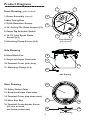
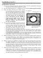
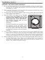
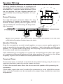
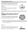
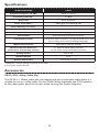
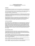
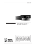
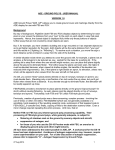
Ceiling Subwoofer
Model CSUB
Installation and Use Manual
© 2008 Bogen Communications, Inc.
All rights reserved.
Specifications subject to change without notice.
54-2171-01B 0810
Product Description
Thank you for choosing Bogen’s CSUB Ceiling Subwoofer. Please familiarize yourself with
the product by reading and reviewing the descriptions and diagrams in this manual.
Bogen’s CSUB delivers unsurpassed performance and value. This subwoofer can be
installed either in suspended ceiling structures or hard surfaces (such as drywall). It is
ready to install with swinging arm clamps that take the place of a tile bridge for installation in suspended ceilings.
A variety of speaker power levels are easily selected via a front panel rotary switch.
Settings for both 70V and 8-ohm systems are provided.
The CSUB features a removable snap-lock input connector, providing easy wire connection for input as well as loop-through to the next speaker.
NOTE
The CSUB is not an outdoor speaker. Do not expose the CSUB to rain or moisture. The
CSUB should only be installed by qualified personnel.
Important Safety Instructions
1) Read these instructions.
2) Keep these instructions.
3) Heed all warnings.
4) Follow all instructions.
5) Do not use this apparatus near water.
6) Clean only with dry cloth.
7) Do not block any ventilation openings. Install in accordance with manufacturer’s
instructions.
8) Do not install near any heat sources such as radiators, heat registers, stoves, or
other apparatus (including amplifiers) that produce heat.
9) Only use attachments/accessories specified by the manufacturer.
10) Recommended amplifier for 64W @ 70V use should be 65W @ 70V. Higherpower amplifiers should be used with additional current limiting, such as a fuse.
11) Refer all servicing to qualified personnel. Servicing is required when the apparatus has
been damaged in any way, such as power supply cord or plug is damaged, liquid has
been spilled or objects have fallen into the apparatus, the apparatus has been
exposed to rain or moisture, does not operate normally, or has been dropped.
To prevent injury, this apparatus must be securely attached to the ceiling
or wall in accordance with the installation instructions.
2
Product Diagrams
1
2
Front Drawing (grille removed)
1. Driver Assembly (internal)
3
2. Bass Tuning Vent
3. Grille Retention Groove
4
4. 24" Ceiling Tile Guide Arrows (×2)
5. Power Tap Selection Switch
7
6. 14-1/2" Joist Space Guide
Arrows (×2)
5
6
Front Drawing
(grille removed)
7. Mounting Clamp Screws (×4)
Side Drawing
8. Metal Back Can
8
9. Snap-Lock Input Connector
9
10. Terminal Cover (side view)
11
11. Mounting Clamps (×4)
10
Side Drawing
Rear Drawing
12
12. Safety Tether Point
13. Snap-Lock Input Connector
14. Terminal Cover (top-down view)
15. Wire Exit Slot
13
16. Terminal Cover Anchor Screw
(×2; one on back,
one below connector)
14
16
15
Rear Drawing
3
Speaker Placement
The low frequency capability of the CSUB allows great flexibility in its placement. While
full-range speakers will typically be installed throughout the ceiling in an evenly spread
pattern, the CSUB can be placed wherever it is most convenient. This usually means
where the subwoofers best meet the needs of the overall sound system, or may sometimes mean where they best fit into the ceiling. This flexibility is useful in irregularlyshaped rooms or when the depth of the area behind the ceiling surface varies.
An important performance parameter to keep in mind is that the location of the subwoofer will affect its output sound pressure level (SPL) within a room. Locating the CSUB
close to a wall will increase its output by approximately 3 dB over locating it toward the
center of the ceiling area. The 3 dB increase will effectively double the amount of output
power coming from the subwoofer. Locating the CSUB in the corner of a room, adjacent
to 2 perpendicular wall surfaces, will increase its output by 6 dB. This 6 dB increase effectively quadruples the output of the subwoofer compared with locating it closer to the
center of the room. The tradeoff for this extra output is a less uniform overall sound
level, especially in large rooms.
Three possible locations for a CSUB Subwoofer
within a larger sound system:
1
CSUB
3
2
Near Corner: + 6 dB Output
CSUB
Center of Ceiling: Optimum Bass Distribution
Most Uniform Sound Level
Near Wall: + 3 dB Output
CSUB
Note:The CSUB may be placed as close as 5" from a wall, provided care is taken to
ensure that mounting clamps are properly extended (see Installation section). If mounting clamps cannot be properly extended, another location must be found.
4
Installation
The unique clamp-mounting system of the Bogen CSUB not only allows mounting in
most types of ceiling surface thicknesses, it takes the ease of installation two significant
steps further:
1. NO TILE BRIDGE IS REQUIRED. Because the mounting clamps are extra-long and
very durable, they can suspend and support the CSUB across the 24" span of a
suspended ceiling. This eliminates the need for the separate tile bridge required
for nearly all ceiling speakers.
2. A uniquely designed clamp screw assembly can be tightened from either the front or
rear, allowing the CSUB to be mounted either by dropping the ceiling tile onto
the rear of the CSUB or by dropping the CSUB into the front of the ceiling tile.
This design can significantly accelerate the installation process.
IMPORTANT
There must be a minimum of 11" of vertical clearance (12-1/4" if using the CK10
Safety Cable Kit) between the front of the mounting surface and any other
structure in the ceiling for the speaker to fit. Before cutting the full hole, investigate for depth and clearance by cutting a small hole, or removing the ceiling
tile, whichever is applicable.
SUSPENDED CEILINGS: The clamps must be able to span the full 24" (approx.)
between the ceiling rails to provide the proper support for the CSUB. If there
is interference with any objects in the ceiling to prevent this, then another ceiling tile location should be chosen.
DRYWALL or OTHER Hard Ceiling Surfaces:The edge of the hole must have clearance of at least 5" on opposite edges of the hole to ensure that the clamps will
be able to support the CSUB.
5
Installation (cont.)
SUSPENDED CEILINGS:
1.
Remove the ceiling tile from the ceiling grid. Cut a 14-1/4" circular hole in the ceiling tile. Use the included template as a guide.
2.
Put the CSUB face down on a workbench or on the floor without grille installed.
3.
Place the ceiling tile over the CSUB, making
sure the ceiling tile is facing out. It is impor- 2×2 Ceiling Tile
Mounting clamps (×4)
tant to note the direction of the clamps:
they must be installed so that they span the
distance from one side of the ceiling tile to
the other (approx. 24", see illustration at
right). The front of the CSUB is
engraved with guide arrows for “24Inch Ceiling Tile” (see Product
Diagrams section). Use these guides
for this installation.
4.
Using an electric powered screwdriver with the
clutch at a low setting, tighten each screw
until the clamps are just snug against the Support rail Mounting clamps extend
tile surface. The CSUB’s clamps can be
to, but do not overhang,
edge of ceiling tile.
tightened from either the front or rear of
the speaker. Use a No. 3 Phillips screwdriver when working from the front. Use a 1/4" flat-blade screwdriver when working from the rear. If working from the rear of the speaker, the screws tighten
COUNTERCLOCKWISE. Do not over-tighten clamps. Once all four clamps
are properly positioned and snug on the ceiling tile, the assembly (CSUB and
ceiling tile) is ready to be mounted in the ceiling grid.
5.
Before installing the grille, make sure you have selected the proper power setting on
the front panel rotary switch. Refer to the Selecting Power Levels section for
instructions on selecting the power level. Install the grille as indicated in the
Speaker Grille Installation & Removal section.
6.
Before mounting the CSUB/tile assembly, make sure the snap-lock input connector
has been connected to the input wires (see Speaker Wiring section). The
CSUB/tile assembly may now be placed in the ceiling grid. By accessing the ceiling space through an adjacent ceiling tile, plug in the snap-lock connector. Attach
the Terminal Cover using the screws provided. If using conduit, refer to the
Terminal Cover section of this manual.
7.
Attach the CK10 Safety Cable, if it is being used, by screwing the eyebolt into the
safety tether point in the rear of the CSUB’s metal enclosure (see Product
Diagrams). This may be a local code requirement. It is certainly a very good safety measure, particularly in suspended ceiling installations. For more information
see the instruction sheet included with the CK10.
6
Installation (cont.)
DRYWALL OR OTHER HARD SURFACES:
1
Be sure you know the location of the ceiling joists before cutting the speaker opening. Cut a 14-1/4" circular hole where the CSUB will be installed. Use the included template as a guide.
2.
Make electrical connections to the snap-lock input connector and then plug it into
the CSUB (see Speaker Wiring section).
3.
Install terminal cover using the supplied screws. If using conduit, refer to the Terminal
Cover section of this manual.
Mounting clamps extend to joists.
4.
Place the CSUB in the ceiling cut-out. To help
properly place the CSUB in the ceiling,
the front of the CSUB is engraved with
guide arrows for “14-1/2" Joist Space”
(see Product Diagrams, #6). Use these
guides for this installation.
Important:
Be certain to position the subwoofer so that
the engraving “14-1/2" Joist Space” aligns
perpendicularly between the studs. Failure to
do so may result in the clamps being unable
to swing out far enough to seat the speaker 14-1/2 Inches between ceiling joists.
properly.
5.
Using an electric screwdriver with the clutch at a low setting, tighten each clamp
screw until the clamps are just snug against the ceiling surface. Once all four
clamps are snug on the ceiling, the four clamp screws should be tightened with
the next clutch setting or with a hand screwdriver. Do not over-tighten clamps.
6.
Before installing the grille, make sure you have selected the proper power setting on
the front panel rotary switch. Refer to the Selecting Power Levels section for
instructions on selecting the power level. Install the grille as indicated in the
Speaker Grille Installation & Removal section.
7
Speaker Wiring
All wiring should be done prior to installation and
then plugged into the rear of the speaker. Wiring is
terminated at a snap-lock input connector. There
are two positive and two negative terminals to
accommodate daisy-chaining of speakers in a system.
Daisy-Chaining
The snap-lock input connector allows for easy
daisy-chaining of speakers by providing a second
terminal of each polarity. See the figures to the
right and below for correct wiring for daisy-chaining of terminals.
Note: When speakers are daisy-chained, disconnecting one speaker from the chain
will disable all speakers further down the chain.
Speaker Polarity
Keep the same polarity terminals wired together to ensure correct speaker polarity. In
order to provide the best possible sound, all speakers – both subwoofers and full-range
speakers – in a system need to be pushing out and pulling in at the same time. Therefore
all must be wired with the same polarity.
If the connections to one speaker in a system are reversed from the others, that speaker’s movement will be out of polarity with the other speakers. This results in a loss of low
frequency response and will effect the overall performance of the system.
Terminal Cover
The terminal cover is attached to the back of the speaker housing using 2 screws. It is
important that both screws be used to mount the cover.
A slot in the terminal cover allows the wires to exit the speaker while protecting the
connections.
If local codes require the use of a conduit for connections or strain relief of the connections, a circular knockout can be removed and a proper fitting installed to meet these
requirements.
8
Selecting Power Levels
The front-mounted selector switch is used to set the
appropriate power level or impedance for your system.
Using your fingers or a flat-blade screwdriver, turn the
knob until the arrow points to the power level you
require.
70V Systems
A power setting scale for 70V systems is labeled on the
switch. Six settings are available, from 2 to 64 watts.
8-ohm Systems
The fully counterclockwise position of the setting switch is the 8-ohm position. This setting is suitable for use with low-impedance amplifiers that typically support 4- or 8-ohm
speakers.
Speaker Grille Installation & Removal
Installation
The speaker grille fits tightly! Push the speaker grille in
until it can go no further. Then, slap around the edge of
the grille to seat the grille. The grille is properly seated
when it is flush with the edge of the bezel.
Note: Black butyl rubber tape is included for extra security in holding the grille in
place. Cut four small pieces and space them equidistant around the groove in the baffle where the grille fits. The butyl rubber tape is quite sticky and it is not necessary
to use an excessive amount.
Removal
Insert a pocketknife blade between the grille and the
bezel about 1/4" deep and then gently pry the grille
upwards. Do this in multiple places around the
circumference of the grille to free the grille.
9
Specifications
SPECIFICATIONS
CSUB
Frequency Response (-6 dB)*
40 Hz to 125 Hz
Sensitivity (1W/1M)*
91 dBspl
Dispersion
Omni-directional
Power Input (Max.)
150W @ 8 ohms; 64W @ 70V
Power Settings (in watts)†
70V: 64, 32, 16, 8, 4, 2
Baffle Material
Fire-rated (94V0) ABS
Back Can Material
Heavy-gauge Steel
Terminations
4-Terminal Snap-Lock Input Connector
Included Accessories
(1) Snap-Lock Input Connector, (1) Steel Terminal Cover with
(2) mounting screws, and (1) Package, Butyl Tape
Optional Accessories
10-Ft. Safety Cable Kit (CK10)
Minimum Vertical Clearance
(From front of mounting surface)
11" Without CK10 Safety Cable Kit
12-1/4" When using CK10 Safety Cable Kit
Ceiling Cutout
14-1/4" dia.
Speaker Weight
19 lb.
Speaker Dimensions
15-1/2" dia. x 11" D
* Half-space response (ceiling-mounted), 8-ohm input
† Front panel, switch-selected
Accessories
CK10 (10-Ft. Safety Cable Kit)
The CK10 is a 10-foot cable with one looped end and an adjustable cable clamp. It is
suitable for use as a safety cable. On the CSUB Ceiling Subwoofer, the CK10 attaches
to the safety tether point on the rear of the housing (see Product Diagrams).
10
Limited Warranty; Exclusion of Certain Damages
The Bogen Ceiling Subwoofer, model CSUB, is warranted to be free from defects in
material or workmanship for three (3) years from the date of sale to the original purchaser. Any part of the product covered by this warranty that, with normal installation and use,
becomes defective will be repaired or replaced by Bogen, at our option, provided the
product is shipped insured and prepaid to: Bogen Factory Service Department,
50 Spring Street, Ramsey, NJ 07446, USA. The product will be returned to you freight
prepaid. This warranty does not extend to any of our products that have been subjected
to abuse, misuse, improper storage, neglect, accident, improper installation or have
been modified or repaired or altered in any manner whatsoever, or where the serial number or date code has been removed or defaced.
THE FOREGOING LIMITED WARRANTY IS BOGEN’S SOLE AND EXCLUSIVE WARRANTY AND THE PURCHASER’S SOLE AND EXCLUSIVE REMEDY. BOGEN MAKES
NO OTHER WARRANTIES OF ANY KIND, EITHER EXPRESS OR IMPLIED, AND ALL
IMPLIED WARRANTIES OF MERCHANTABILITY OR FITNESS FOR A PARTICULAR
PURPOSE ARE HEREBY DISCLAIMED AND EXCLUDED TO THE MAXIMUM
EXTENT ALLOWABLE BY LAW. Bogen’s liability arising out of the manufacture, sale or
supplying of products or their use or disposition, whether based upon warranty, contract,
tort or otherwise, shall be limited to the price of the product. IN NO EVENT SHALL
BOGEN BE LIABLE FOR SPECIAL, INCIDENTAL OR CONSEQUENTIAL DAMAGES
(INCLUDING, BUT NOT LIMITED TO, LOSS OF PROFITS, LOSS OF DATA OR LOSS
OF USE DAMAGES) ARISING OUT OF THE MANUFACTURE, SALE OR SUPPLYING
OF PRODUCTS, EVEN IF BOGEN HAS BEEN ADVISED OF THE POSSIBILITY OF
SUCH DAMAGES OR LOSSES. Some States do not allow the exclusion or limitation of
incidental or consequential damages, so the above limitation or exclusion may not apply
to you. This warranty gives you specific legal rights, and you may also have other rights
which vary from State to State.
7/22/2008
11
50 Spring Street, Ramsey, NJ 07446, U.S.A.
Tel. 201-934-8500, Fax: 201-934-9832, www.bogen.com