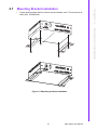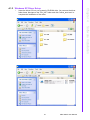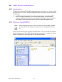
1
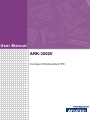
User Manual ARK-3202V Compact Embedded IPC Copyright The documentation and the software included with this product are copyrighted 2010 by Advantech Co., Ltd. All rights are reserved. Advantech Co., Ltd. reserves the right to make improvements in the products described in this manual at any time without notice. No part of this manual may be reproduced, copied, translated or transmitted in any form or by any means without the prior written permission of Advantech Co., Ltd. Information provided in this manual is intended to be accurate and reliable. However, Advantech Co., Ltd. assumes no responsibility for its use, nor for any infringements of the rights of third parties, which may result from its use. Acknowledgements Award is a trademark of Award Software International, Inc. VIA is a trademark of VIA Technologies, Inc. IBM, PC/AT, PS/2 and VGA are trademarks of International Business Machines Corporation. Intel® and Pentium® are trademarks of Intel Corporation. Microsoft Windows® is a registered trademark of Microsoft Corp. RTL is a trademark of Realtek Semi-Conductor Co., Ltd. ESS is a trademark of ESS Technology, Inc. UMC is a trademark of United Microelectronics Corporation. SMI is a trademark of Silicon Motion, Inc. Creative is a trademark of Creative Technology LTD. CHRONTEL is a trademark of Chrontel Inc. All other product names or trademarks are properties of their respective owners. For more information about this and other Advantech products, please visit our website at: http://www.advantech.com/ http://www.advantech.com/ePlatform/ For technical support and service, please visit our support website at: http://support.advantech.com.tw/support/ ARK-3202V User Manual Part No. 2006320220 Edition 1 Printed in China December 2010 ii Product Warranty (2 years) Advantech warrants to you, the original purchaser, that each of its products will be free from defects in materials and workmanship for two years from the date of purchase. This warranty does not apply to any products which have been repaired or altered by persons other than repair personnel authorized by Advantech, or which have been subject to misuse, abuse, accident or improper installation. Advantech assumes no liability under the terms of this warranty as a consequence of such events. Because of Advantech’s high quality-control standards and rigorous testing, most of our customers never need to use our repair service. If an Advantech product is defective, it will be repaired or replaced at no charge during the warranty period. For outof-warranty repairs, you will be billed according to the cost of replacement materials, service time and freight. Please consult your dealer for more details. If you think you have a defective product, follow these steps: 1. Collect all the information about the problem encountered. (For example, CPU speed, Advantech products used, other hardware and software used, etc.) Note anything abnormal and list any onscreen messages you get when the problem occurs. 2. Call your dealer and describe the problem. Please have your manual, product, and any helpful information readily available. 3. If your product is diagnosed as defective, obtain an RMA (return merchandize authorization) number from your dealer. This allows us to process your return more quickly. 4. Carefully pack the defective product, a fully-completed Repair and Replacement Order Card and a photocopy proof of purchase date (such as your sales receipt) in a shippable container. A product returned without proof of the purchase date is not eligible for warranty service. 5. Write the RMA number visibly on the outside of the package and ship it prepaid to your dealer. Declaration of Conformity FCC Class A Note: This equipment has been tested and found to comply with the limits for a Class A digital device, pursuant to part 15 of the FCC Rules. These limits are designed to provide reasonable protection against harmful interference when the equipment is operated in a commercial environment. This equipment generates, uses, and can radiate radio frequency energy and, if not installed and used in accordance with the instruction manual, may cause harmful interference to radio communications. Operation of this equipment in a residential area is likely to cause harmful interference in which case the user will be required to correct the interference at his own expense. iii ARK-3202V User Manual Technical Support and Assistance 1. 2. Visit the Advantech web site at www.advantech.com/support where you can find the latest information about the product. Contact your distributor, sales representative, or Advantech's customer service center for technical support if you need additional assistance. Please have the following information ready before you call: – Product name and serial number – Description of your peripheral attachments – Description of your software (operating system, version, application software, etc.) – A complete description of the problem – The exact wording of any error messages Warnings, Cautions and Notes Warning! Warnings indicate conditions, which if not observed, can cause personal injury! Caution! Cautions are included to help you avoid damaging hardware or losing data. e.g. There is a danger of a new battery exploding if it is incorrectly installed. Do not attempt to recharge, force open, or heat the battery. Replace the battery only with the same or equivalent type recommended by the manufacturer. Discard used batteries according to the manufacturer's instructions. Note! Notes provide optional additional information. ARK-3202V User Manual iv Safety Instructions 1. 2. 3. 4. 5. 6. 7. 8. 9. 10. 11. 12. 13. 14. 15. 16. 17. 18. 19. 20. 21. 22. Read these safety instructions carefully. Keep this User Manual for later reference. Disconnect this equipment from any AC outlet before cleaning. Use a damp cloth. Do not use liquid or spray detergents for cleaning. For plug-in equipment, the power outlet socket must be located near the equipment and must be easily accessible. Keep this equipment away from humidity. Put this equipment on a reliable surface during installation. Dropping it or letting it fall may cause damage. The openings on the enclosure are for air convection. Protect the equipment from overheating. DO NOT COVER THE OPENINGS. Make sure the voltage of the power source is correct before connecting the equipment to the power outlet. Position the power cord so that people cannot step on it. Do not place anything over the power cord. All cautions and warnings on the equipment should be noted. If the equipment is not used for a long time, disconnect it from the power source to avoid damage by transient overvoltage. Never pour any liquid into an opening. This may cause fire or electrical shock. Never open the equipment. For safety reasons, the equipment should be opened only by qualified service personnel. If one of the following situations arises, get the equipment checked by service personnel: The power cord or plug is damaged. Liquid has penetrated into the equipment. The equipment has been exposed to moisture. The equipment does not work well, or you cannot get it to work according to the user's manual. The equipment has been dropped and damaged. The equipment has obvious signs of breakage. Do not leave this equipment in an environment where the storage temperature may go below -20° C (-4° F) or above 60° C (140° F). This could damage the equipment. The equipment should be in a controlled environment. CAUTION: Danger of explosion if battery is incorrectly replaced. Replace only with the same or equivalent type recommended by the manufacturer, discard used batteries according to the manufacturer’s instructions. The sound pressure level at the operator's position according to IEC 704-1:1982 is no more than 70 dB (A). RESTRICTED ACCESS AREA: The equipment should only be installed in a Restricted Access Area. DISCLAIMER: This set of instructions is given according to IEC 704-1. Advantech disclaims all responsibility for the accuracy of any statements contained herein. This product is connected to a fuse box in the passenger compartment before it connected to the vehicle battery, and the fuse in a fuse box is UL listed and automotive fuse. Use the appropriate flexible and SAE wiring to connect to a fuse box. This product is installed in the passenger compartment. This product must be installed and maintained by qualified service personnel. v ARK-3202V User Manual 23. This device complies with Part 15 of the FCC rules. Operation is subject to the following two conditions: (1). this device may not cause harmful interference, and (2). this device must accept any interference received, including interference that may cause undesired operation. Packing List Before installation, please ensure the following items have been shipped: 1 x ARK-3202V Unit 2 x Desk/Wall mount plate 1 x 3-pin Phoenix DC power connector 1 x Utility CD 1 x Registration and 2 years Warranty card Ordering Information Model Number Description ARK-3202V -S6A1E Intel® ATOM N270 1.6 GHz Compact Embedded Box IPC, with 2 MiniPCIe , on-board GPS, and 5 COM Optional Accessories Part Number Description 1757003659 ADAPTER AC 65W DC19V/3.42A FSP065-RAC 1700001947 Power Cable 2-pin 180 cm, USA for ARK-338X 1700001948 Power cable 2-pin 180 cm, Europe for ARK-338X 1700001949 Power cable 2-pin 180 cm, UK for ARK-338X 1700009398 LVDS Power cable for ARK-3202 1700018855 DIO Cable for ARK-3202V 1700018308 M Cable SCSI 26P(M) to D-SUB 9P(M)X3 ARK-3202V User Manual vi Contents Chapter 1 General Introduction ...........................1 1.1 1.2 Introduction ............................................................................................... 2 Product Feature ........................................................................................ 2 1.2.1 General ......................................................................................... 2 1.2.2 Display .......................................................................................... 2 1.2.3 Power Consumption...................................................................... 2 Hardware Specification ............................................................................. 2 1.3.1 System .......................................................................................... 2 1.3.2 Memory ......................................................................................... 3 1.3.3 Input/Output .................................................................................. 3 1.3.4 Graphics........................................................................................ 3 1.3.5 Ethernet LAN ................................................................................ 3 1.3.6 Industrial Features ........................................................................ 3 Mechanical Specification........................................................................... 4 1.4.1 Dimensions ................................................................................... 4 Figure 1.1 ARK-3202V Mechanical Dimension Drawing ............. 4 1.4.2 Weight........................................................................................... 4 Power Requirement .................................................................................. 4 1.5.1 System Power............................................................................... 4 1.5.2 RTC Battery .................................................................................. 4 Environmental Specifications .................................................................... 5 1.6.1 Operation Temperature................................................................. 5 1.6.2 Relative Humidity .......................................................................... 5 1.6.3 Storage Temperature.................................................................... 5 1.6.4 Vibration Loading during Operation .............................................. 5 1.6.5 Shock during Operation ................................................................ 5 1.6.6 Safety............................................................................................ 5 1.6.7 EMC .............................................................................................. 5 1.3 1.4 1.5 1.6 Chapter 2 Hardware installation ..........................7 2.1 ARK-3202V I/O Indication ......................................................................... 8 Figure 2.1 ARK-3202V Front View ............................................. 8 Figure 2.2 ARK-3202V Rear View .............................................. 8 ARK-3202V Front Side External I/O Connectors ...................................... 9 Table 2.1: Connector Table ......................................................... 9 Figure 2.3 PCI-7030 for ARK-3202V ......................................... 21 ARK-3202V COM Jumper and Switch Setting ........................................ 23 2.3.1 COM3.......................................................................................... 23 2.3.2 COM4.......................................................................................... 24 2.3.3 COM5.......................................................................................... 24 Memory Installation ................................................................................. 25 Figure 2.4 Memory Installation .................................................. 25 Compact Flash Installation...................................................................... 26 Figure 2.5 CF Card installation .................................................. 26 MiniPCIe Add-on Card Installation .......................................................... 26 Figure 2.6 MiniPCIe Add-on card installation ............................ 26 Mounting Bracket installation ................................................................. 27 Figure 2.7 Mounting brackets installation .................................. 27 2.2 2.3 2.4 2.5 2.6 2.7 Chapter 3 BIOS settings .....................................29 3.1 BIOS Introduction.................................................................................... 30 vii ARK-3202V User Manual Chapter 3.2 BIOS Setup ............................................................................................. 30 3.2.1 Main Menu .................................................................................. 31 3.2.2 Standard CMOS Features .......................................................... 32 3.2.3 Advanced BIOS Features ........................................................... 33 3.2.4 Advanced Chipset Features ....................................................... 34 3.2.5 Integrated Peripherals ................................................................ 36 3.2.6 USB Device Setting .................................................................... 39 3.2.7 Security Chip Configuration (Optional Item) ............................... 40 3.2.8 Power Management Setup ......................................................... 40 3.2.9 PnP/PCI Configurations.............................................................. 42 3.2.10 PC Health Status ........................................................................ 43 3.2.11 Frequency/Voltage Control ......................................................... 44 3.2.12 Load Setup Defaults ................................................................... 45 3.2.13 Set Password.............................................................................. 45 3.2.14 Save & Exit Setup....................................................................... 47 3.2.15 Quit without Saving..................................................................... 47 4 Software Installation......................... 49 4.1 Chipset Driver Installation ....................................................................... 50 4.1.1 Before You Begin........................................................................ 50 4.1.2 Introduction ................................................................................. 50 4.1.3 Windows XP Driver Setup .......................................................... 51 VGA Driver Installation............................................................................ 52 4.2.1 Introduction ................................................................................. 52 4.2.2 Windows Vista/XP/2000 ............................................................. 52 LAN Driver Installation ............................................................................ 53 4.3.1 Introduction ................................................................................. 53 4.3.2 Installation................................................................................... 53 4.3.3 Win XP/Vista Driver Setup.......................................................... 53 Audio Driver Installation .......................................................................... 54 GPS Test Setting Guide.......................................................................... 55 4.2 4.3 4.4 4.5 Appendix A ARK In-Vehicle Series Power Management ...................................... 61 A.1 A.2 Introduction ............................................................................................. 62 Pin Definition & Jumper Setting .............................................................. 62 A.2.1 Pin Definition............................................................................... 62 A.2.2 Hardware Setup.......................................................................... 62 Software Setup ....................................................................................... 63 A.3 ARK-3202V User Manual viii Chapter 1 1 General Introduction This chapter gives background information on ARK-3202V series. 1.1 Introduction ARK-3202V offers industrial-grade, high computing power, multiple I/O and low-noise operation for a range of in-vehicle applications. ARK-3202V features a vehicle-friendly power design (compliant with ISO-7637-2), wireless communications, on-board GPS receiver, in-vehicle certification (eMark), anti-vibration and shock resistant design (MIL-810), and easy installation that speeds up system integrators' time-to-market and reduces costs for space-critical, in-vehicle applications. The ARK-3202V can be used as a standalone system, wall-mounted and desktop mounted comes in a footprint of only 220 mm x 68 mm x 200 mm (8.66" x 2.67" x 7.87"). The rugged cast aluminum case not only provides great protection from EMI, shock/vibration, cold and heat, but also passive cooling for quiet fanless operation. The ARK-3202V is a great platform for in-vehicle applications as it supports GPS and wireless HSDPA communications. It also supports full HD performance with optional VGA and DVI displays and answers the demand by offering 5 x USB 2.0 ports, 2 x Giga LAN port, audio function and 5 x COM ports packed into a small rugged unit and powered by an Intel ATOM N270 1.6 GHz processor. The ARK-3202V Compact Embedded IPC supports 1 x Compact Flash card for storage and 2 MiniPCIe for expansion. 1.2 Product Feature 1.2.1 General Intel ATOM N270 Processor 1.6 GHz Dual display and support for wide screen with high resolution Supports 2 GbE, 5 USB 2.0, audio and 5 COM (COM1 & COM2 are RS-232, and COM3 to COM5 support RS-232/422/485 and RS-485 with auto flow control) One internal CompactFlash socket Easy integration, easy maintenance, and wide input voltage range 1.2.2 Display Dual display: CRT + DVI-D (optional) LVDS support: Supports 36-bit LVDS interface (Optional) 1.2.3 Power Consumption Typical: 13.3 W (CPU is Intel ATOM N270 Processor 1.6 GHz and w/o expansion) Max.: 17 W (CPU is Intel ATOM N270 Processor 1.6 GHz and w/o expansion) 1.3 Hardware Specification 1.3.1 System CPU: Intel® Atom. N270 1.6 GHz FSB 533 MHz BIOS: AWARD 4 Mbit, SPI System chipset: Intel 945GSE with ICH7M CF interface: Supports CompactFlash socket for type I/II CompactFlash disk ARK-3202V User Manual 2 RAM: Up to 2 GB in 1 slots 200-pin SODIMM sockets. Supports DDRII 400/533 SDRAM 1.3.3 Input/Output 1.3.4 Graphics Controller: Chipset integrated VGA controller Display memory: Dynamically shared system memory up to 224 MB CRT: Up to 1920 x 1080 resolution, 400 MHz RAMDAC LVDS: Supports single channel 18-bit/ dual channel 36-bit LVDS, Up to SXGA 1280 x 1024 DVI: Supports maximum pixel lock of 400 MHz, up to 1920 x 1080 resolutions @ 75 Hz refresh rate 1.3.5 Ethernet LAN Supporting dual 10/100/1000 Mbps Ethernet port (s) via PCI Express x1 bus which provides 500 MB/s data transmission rate Controller: Intel 82574L Chipset 1.3.6 Industrial Features Watchdog timer: Can generate a system reset. The watchdog timer is programmable and can be set from 1 to 255 seconds or 1 to 255 minutes. 3 ARK-3202V User Manual General Introduction Serial ports: Five serial ports, 2 x RS-232 onboard, 3 x RS-232/422/485 with auto flow Keyboard and PS/2 mouse connector: 6-pin mini-DIN connectors for PS/2 keyboard and mouse USB port: 5 x USB 2.0 with 480 Mbps DIO connector: 8-bit general purpose input/output Chapter 1 1.3.2 Memory 1.4 Mechanical Specification 1.4.1 Dimensions Figure 1.1 ARK-3202V Mechanical Dimension Drawing 1.4.2 Weight 3 kg (6.6 lb) 1.5 Power Requirement 1.5.1 System Power Minimum power input: DC 9 V ~ 32 V, 7.2 A ~ 2.0 A 1.5.2 RTC Battery 3 V / 195 mAH BR2032 ARK-3202V User Manual 4 Chapter 1 1.6 Environmental Specifications 1.6.1 Operation Temperature With Industrial Grade CompactFlash disk: -20 ~ 60° C 1.6.2 Relative Humidity 95% @ 40° C (non-condensing) -40 ~ 85° C (-40 ~ 185° F) 1.6.4 Vibration Loading during Operation With CompactFlash disk: 5 Grms, IEC 60068-2-64, random, 5 ~ 500 Hz, 1 Oct./ min, 1 hr/axis. 1.6.5 Shock during Operation With CompactFlash disk: 50 G, IEC 60068-2-27, half sine, 11 ms duration 1.6.6 Safety UL, CCC, BSMI, E-Mark E13 1.6.7 EMC CE, FCC, CCC, BSMI 5 ARK-3202V User Manual General Introduction 1.6.3 Storage Temperature ARK-3202V User Manual 6 Chapter 2 2 Hardware installation This chapter introduces external IO and the installation of ARK3202V Hardware. 2.1 ARK-3202V I/O Indication USB4 DIO LAN-1 LAN-2 USB3 VGA USB0 PS/2 DC INPUT COM-1 COM-2 COM3~5 Figure 2.1 ARK-3202V Rear View PWR LED HDD LED ON/OFF USB2 MIC USB1 LINE-OUT Figure 2.2 ARK-3202V Front View ARK-3202V User Manual 8 Table 2.1: Connector Table Front Panel Indicate and SW Header (By Cable to AMO-0102) COM1-5 COM Port Header VGA1 VGA Port LAN1, 2 LAN Port X 2 USB0 USB I/O Port KBMS1 PS2 Keyboard & Mouse USB12 USB X 2 Header (By Cable to AMO-0102) USB34 USB X 2 Header (By Cable to I/O) SPI1 BIOS Socket DVI1 DVI Header (By Cable to I/O Optional) LVDS1 LVDS Header (By Cable to I/O Optional) INV1 LVDS power Header (By Cable to I/O) HDAUD1 HD AUDIO Header (By Cable to AMO-0102) DIMMA1 DDR2 Socket ATX1 Power Header (By Cable to PCM-257) Hardware installation JFP1 JFP1 Front Panel Indicate and SW Header Part Number 1653005200 Package PH5x2P-2.54 Description PIN HEADER 5*2P 180D (M) 2.54 mm DIP WO/Pb Pin Name 1 HDLED_A 2 GF_HDDLED# 3 PWRLED_A 4 PWRLED_C 5 SUSLED_A 6 SUSLED_C 7 SYS_RST# 8 GND 9 PANSWIN#_R 10 GND 9 Chapter 2 2.2 ARK-3202V External I/O Connectors ARK-3202V User Manual COM1, COM2 COM Port Header Part Number 1653210260 Package BH10x2P-S2.00 Description BOX HEADER 10*2P 180D(M) 2.0mm SMD W/O Pb Pin Name 1 DCDA 2 DSRA 3 SINA 4 RTSA 5 SOUTA 6 CTSA 7 DTRA 8 RIA 9 GND 10 GND 11 DCDB 12 DSRB 13 SINB 14 RTSB 15 SOUTB 16 CTSB 17 DTRB 18 RIB 19 GND 20 GND ARK-3202V User Manual 10 Part Number 1654515304 Package DSUB15P Description D-SUB CONN. 15P 90D(F) DIP 5mm BLUE W/O Pb Pin Name 1 CRT_R 2 CRT_G 3 CRT_B 4 NC 5 GND_VGA 6 CRT_FOC_ON 7 GND_VGA 8 GND_VGA 9 +V5_VGA 10 GND_VGA 11 NC 12 CRT_DDAT 13 CRT_HSYNC 14 CRT_VSYNC 15 CRT_DCLK 16 GND_F 17 GND_F Hardware installation VGA Port Chapter 2 VGA1 11 ARK-3202V User Manual LAN1, LAN2 LAN Port X 2 Part Number 1652003274 Package RJ45-2x1+FMR Description PHONE JACK RJ45 28P DIP Gold flash RTB-19GB9J1A Pin Net Name A1 LAN1_MDI0+ A2 LAN1_MDI0- A3 LAN1_MDI1+ A4 LAN1_MDI1- A5 LAN1_1P8R A6 TCT1 A7 LAN1_MDI2+ A8 LAN1_MDI2- A9 LAN1_MDI3+ A10 LAN1_MDI3- A11 LAN1_LED1_R A12 +V3.3_LAN1 A13 LAN1_LINK1000# A14 LAN1_LINK100# B1 LAN2_MDI0+ B2 LAN2_MDI0- B3 LAN2_MDI1+ B4 LAN2_MDI1- B5 LAN2_1P8R B6 TCT2 B7 LAN2_MDI2+ B8 LAN2_MDI2- B9 LAN2_MDI3+ B10 LAN2_MDI3- B11 LAN1_LED2 B12 +V3.3_LAN2 B13 LAN2_LINK1000# B14 LAN2_LINK100# H1 NC H2 NC H3 GND_F H4 GND_F ARK-3202V User Manual 12 Chapter 2 Hardware installation ARK-3202V User Manual 13 USB5 USB I/O Port Part Number 1654904105 Package USB4P Description USB CON. 4P 90D(F) DIP A TYPE RoHS Pin Name 1 USBV2 2 USBP4- 3 USBP4+ 4 GND 5 GND_F 6 GND_F 7 GND_F KBMS1 PS2 Keyboard & Mouse Part Number 1654003199 Package MINIDIN6P Description MINIDIN 6P Short body W/Shielding90D(F) DIP Number Net Name 1 R_KDAT 2 R_MDAT 3 GND 4 VCC_M 5 R_KCLK 6 R_MCLK 7 GND_F 8 GND_F 9 GND_F ARK-3202V User Manual 14 Part Number 1655002182 Package WB10P-2.0 Description Wafer box conn. DIP 2*5P 180D(M) 2.0mm NO.10P Pin Name 1 USBV0 2 USBV0 3 USBD0- 4 USBD1- 5 USBD0+ 6 USBD1+ 7 GND 8 GND 9 FGND SPI1 BIOS Socket Part Number 1651000682 Package IC SKT8P Description IC SKT 8P SMD WO/Pb C ACA-SPI-004-K01 Pin Name 1 SPI_CS# 2 SPI_MISO 3 SPI_WP# 4 GND 5 SPI_MOSI 6 SPI_CLK 7 SPI_HD# 8 +V3.3_SPI Hardware installation USB X 2 Header Chapter 2 USB1, 2 and USB3, 4 15 ARK-3202V User Manual DVI1 DVI Header Part Number 1653910261 Package DF13-20P-S1.25 Description *CONN. SMD 10*2P 180D(M)DF13-20DP-1.25V(54) HRS Pin Name 1 TDC0- 2 +V5_TMDS 3 TDC0+ 4 TLC- 5 GND 6 TLC+ 7 TDC1- 8 GND 9 TDC1+ 10 SC_DDC 11 GND 12 SD_DDC 13 TDC2- 14 HPDETT 15 TDC2+ 16 NC 17 +V5_TMDS 18 NC 19 NC 20 NC 21 NC 22 NC 23 NC 24 NC ARK-3202V User Manual 16 Part Number 1653920200 Package DF13-40P-S1.25 Description *CONN. 40P 90D 1.25mm SMD WO/Pb DF13-40DP-1.25V Number Net Name 1 +V_LCD 2 +V_LCD 3 GND 4 GND 5 +V_LCD 6 +V_LCD 7 LVDS0_D0- 8 LVDS1_D0- 9 LVDS0_D0+ 10 LVDS1_D0+ 11 GND 12 GND 13 LVDS0_D1- 14 LVDS1_D1- 15 LVDS0_D1+ 16 LVDS1_D1+ 17 GND 18 GND 19 LVDS0_D2- 20 LVDS1_D2- 21 LVDS0_D2+ 22 LVDS1_D2+ 23 GND 24 GND 25 LVDS0_CLK- 26 LVDS1_CLK- 27 LVDS0_CLK+ 28 LVDS1_CLK+ 29 GND 30 GND 31 LVDS0_DDC_SC 32 LVDS0_DDC_SD 33 GND 34 GND 35 NC 36 NC 37 NC 38 NC 39 NC 40 NC 41 NC Hardware installation LVDS Header Chapter 2 LVDS1 17 ARK-3202V User Manual 42 NC 43 NC 44 NC INV1 LVDS power Header Part Number 1655305020 Package WB5P-2.00 Description WAFER BOX 2.0mm 5P 180D(M) W/LOCK Pin Name 1 +V12_INV1 2 GND 3 LVDS0_a_ENABKL 4 VBR 5 +V5_INV1 ARK-3202V User Manual 18 Part Number 1653006204 Package PH6x2P-2.00 Description PIN HEADER 6*2P 180D(M) 2.0mm DIP NO.12P Pin Name 1 +V5_Audio 2 GND 3 AZ_SYNC 4 AZ_BITCLK 5 AZ_SDOUT 6 AZ_SDIN0_R 7 AZ_SDIN1_R 8 AZ_RST# 9 +V12_Audio 10 GND 11 GND Hardware installation HD AUDIO Header Chapter 2 HDAUD1 19 ARK-3202V User Manual DIMMA1 SODIMM DDR2 Socket Part Number 1651000087 Footprint SODIMM200P Description SKT DIMM 200P DDR2 H=6.5mm STD SMD WO/Pb ATX1 ATX Power Header Part Number 1655412110 Package ATX6x2P-R4.20 Description WAFER 2*6P 4.2mm 90D(M) W/LOCK 4200-WR-A1 Number Net Name 1 GND 2 +V5 3 +V5 4 GND 5 +V5 6 +V5 7 GND 8 GND 9 +V5SB 10 PSON_SIO# 11 GND 12 +V12 ARK-3202V User Manual 20 Chapter 2 Hardware installation Figure 2.3 PCI-7030 for ARK-3202V Jumper Setting CMOS1 Clear CMOS Setting JLVDS1 LVDS Voltage Setting JWDT1 Watch Dog Setting CMOS1 Clear CMOS Setting Part Number 1653003100 Package PH3x1P-2.54 Description PIN HEADER 3*1P 180D(M) 2.54mm DIP WO/Pb Setting Function 1-2 Normal (Default) 2-3 Clear 21 ARK-3202V User Manual JLVDS1 LVDS Voltage Setting Part Number 1653003100 Package PH3x1P-2.54 Description PIN HEADER 3*1P 180D(M) 2.54mm DIP WO/Pb Setting Function 1-2 3.3 V (Default) 2-3 5V JWDT1 Watch Dog Setting Part Number 1653003100 Package PH3x1P-2.54 Description PIN HEADER 3*1P 180D(M) 2.54mm DIP WO/Pb Setting Function 1-2 By South Bridge 2-3 By SIO (Default) ARK-3202V User Manual 22 Chapter 2 2.3 ARK-3202V COM Jumper and Switch Setting Hardware installation 2.3.1 COM3 (RS232 is default) Jumper J3 7-8 (Default) for COM3 Ring 2-4 for COM3 provide 5V 23 ARK-3202V User Manual 2.3.2 COM4 (RS232 is default) Jumper J3 9-10 (Default) for COM4 Ring 1-3 for COM4 provide 5V 2.3.3 COM5 (RS232 is default) Jumper J4 7- 8 (Default) for COM5 Ring 1-3 for COM5 provide 5V ARK-3202V User Manual 24 Chapter 2 2.4 Memory Installation Step 1: Remove the Heatsink by loosening the fixing screws. Step 2: Remove the heatspreader by unscrewing the four screws. Step 3: Insert the memory module into the SODIMM socket. 2 3 Figure 2.4 Memory Installation 25 ARK-3202V User Manual Hardware installation 1 2.5 Compact Flash Installation step 1: Remove the bottom cover by unscrewing the four screws. Step 2: Unscrew CF bracket and install the compactFlash. 1 D HD CFC ard Figure 2.5 CF Card installation 2.6 MiniPCIe Add-on Card Installation Step 1: Remove the bottom cover by unscrewing the four screws. Step 2: Install Mini PCIe add-on module. M in i-p ciE Figure 2.6 MiniPCIe Add-on card installation ARK-3202V User Manual 26 2 Mounting Bracket installation 1. Fasten both brackets with four screws onto the bottom cover. The screw size is: M4*8 (PN: 1930003238) Chapter 2 2.7 Hardware installation Figure 2.7 Mounting brackets installation 27 ARK-3202V User Manual ARK-3202V User Manual 28 Chapter 3 3 BIOS settings This chapter introduces how to set BIOS configuration data. 3.1 BIOS Introduction Advantech provides the full-featured AwardBIOS 6.0, which delivers superior performance, compatibility and functionality for today’s applications. The modular, adaptable AwardBIOS 6.0 supports the broadest range of third-party peripherals and all popular chipsets, plus Intel, AMD, nVidia, VIA, and compatible CPUs from 386 through to Pentium and AMD Geode, K7 and K8 (including multiple processor platforms), and VIA Eden C3 and C7 CPU. You can use Advantech’s utilities to select and install features as needed. 3.2 BIOS Setup The ARK-3202V series system has build-in AwardBIOS with a CMOS SETUP utility which allows users to configure required settings or to activate certain system features. The CMOS SETUP saves the configuration in the CMOS RAM of the motherboard. When the power is turned off, the battery on the board supplies the necessary power to the CMOS RAM. When the power is turned on, press the <Del> button during the BIOS POST (PowerOn Self Test) which will take you to the CMOS SETUP screen. CONTROL KEYS < ↑ >< ↓ >< ← >< → > Move to highlight item <Enter> Select Item <Esc> Main Menu - Quit and not save changes into CMOS Sub Menu - Exit current page and return to Main Menu <Page Up/+> Increase the numeric value or make changes <Page Down/-> Decrease the numeric value or make changes <F1> General help, for Setup Sub Menu <F2> Item Help <F5> Load Previous Values <F7> Load Optimized Default <F10> Save all CMOS changes ARK-3202V User Manual 30 Press <Del> to enter AwardBIOS CMOS Setup Utility, the Main Menu will appear on the screen. Use arrow keys to select among the items and press <Enter> to accept or enter the sub-menu. Chapter 3 3.2.1 Main Menu BIOS settings Standard CMOS Features This setup page includes all the items in standard compatible BIOS. Advanced BIOS Features This setup page includes all the items of Award BIOS enhanced features. Advanced Chipset Features This setup page includes all the items of Chipset configuration features. Integrated Peripherals This setup page includes all onboard peripheral devices. Security chip configuration This SETUP page includes all the items of Trusted Module Configuration features. This sub-menu item only appears when the Trusted Module is plugged in. Power Management Setup This setup page includes all the items of Power Management features. PnP/PCI Configurations This setup page includes PnP OS and PCI device configuration. PC Health Status This setup page includes the system auto detect CPU and system temperature, voltage, fan speed. Frequency/Voltage Control This setup page includes CPU host clock control, frequency ratio and voltage. Load Setup Defaults This setup page includes the “load system optimized” value, so the system operates under optimum performance configuration. Set Password Establish, change or disable password. Save & Exit Setup Save CMOS value settings to CMOS and exit BIOS setup. 31 ARK-3202V User Manual Exit Without Saving Abandon all CMOS value changes and exit BIOS setup. 3.2.2 Standard CMOS Features Date The date format is <weekday>, <month>, <day>, <year>. Weekday From Sun to Sat, determined and displayed by BIOS only Month From Jan. to Dec. Day From 1 to 31 Year From 1999 through 2098 Time The time format is <hour> <minute> <second>, based on 24-hour time. IDE Channel 0 Master/Slave IDE HDD Auto-Detection Press "Enter" for automatic device detection. Video Select EGA or VGA display. Halt on The item determines whether the computer will stop if an error is detected during power up. No Errors The system boot will not stop for any error. All Errors Whenever the BIOS detects a non-fatal error the system will be stopped. All, But Keyboard The system boot will not stop for a keyboard error; it will stop for all other errors. (Default value) Base Memory The POST of the BIOS will determine the amount of base (or conventional) memory installed in the system. Extended Memory The BIOS POST will determine the amount of extended memory (above 1 MB in CPU’s memory address map) installed in the system. ARK-3202V User Manual 32 Total Memory This item displays the total system memory size. Chapter 3 3.2.3 Advanced BIOS Features BIOS settings CPU Feature This item allows users to adjust CPU features. Hard Disk Boot Priority This item allows users to select boot sequence for system device HDD, USBHDD, SCSI, RAID. Virus Warning [Disabled] Enables or disables the virus warning. CPU L1 & L2 Cache [Enabled] This item allows users to enable CPU L1 and L2 cache. Hyper-Threading Technology While using a CPU with Hyper-Threading technology, you can select "Enabled" to enable Hyper-Threading Technology in an OS which supports Hyper-Threading Technology or select "Disabled" for other OSs which do not support HyperThreading technology. Quick Power On Self Test [Enabled] This field speeds up the Power-On Self Test (POST) routine by skipping retesting a second, third and forth time. Setup setting default is enabled. First / Second / Third / Other Boot Drive Hard Disk Select boot device priority by Hard Disk. CDROM Select boot device priority by CDROM. USB-FDD Select boot device priority by USB-FDD. USB-ZIP Select boot device priority by USB-ZIP. USB-CDROM Select boot device priority by USB-CDROM. LAN Select boot device priority by LAN. Disabled Disable this boot function. Gate A20 Option [Fast] 33 ARK-3202V User Manual This item enables users to switch A20 control by port 92 or not. Typematic Rate Setting This item enables users to set the two typematic controls items. – Typematic Rate (Chars/Sec) This item controls the speed at which the system registers auto-repeated keystrokes. The eight settings are 6, 8, 10, 12, 15, 20, 24 and 30. – Typematic Delay (Msec) This item sets the keypress time delay before autorepeat begins. Four delay rate options are 250, 500, 750 and 1000. Security Option [Setup] System System will not boot and refuses access to Setup page if the correct password is not entered at the prompt. Setup System will boot, but access to Setup requires password (default value). APIC Mode [Enabled] This item allows users to enabled of disabled “Advanced Programmable Interrupt Controller”. APIC is implemented in the motherboard and must be supported by the operating system, and it extends the number of IRQ's available. 3.2.4 Advanced Chipset Features Note! This “Advanced Chipset Features” page controls configuration of the board’s chipset. This page is chipset dependent; screens may differ somewhat depending on the chipset. It is strongly recommended that only technical users make changes to the default settings. DRAM Timing Selectable [By SPD] This item enables users to set the optimal timings for items 2 through 5; system default setting “By SPD” follows the SPD information and ensures the system runs stably with optimal performance. CAS Latency Time [Auto] ARK-3202V User Manual 34 35 ARK-3202V User Manual BIOS settings Chapter 3 This item enables users to set the timing delay in clock cycles before SDRAM starts a read command after receiving it. DRAM RAS# to CAS# Delay [Auto] This item enables users to set the timing of the transition from RAS (row address strobe) to CAS (column address strobe) as both rows and column are separately addressed shortly after DRAM is refreshed. DRAM RAS# Precharge [Auto] This item enables users to set the DRAM RAS# precharge timing, system default is setting to “Auto” to reference the data from SPD ROM. Precharge Delay (tRAS) [Auto] This item allows user to adjust memory precharge time. Video BIOS Cacheable [Disabled] This item allows the video BIOS to be cached to allow faster execution and better performance. On-Chip Frame Buffer Size [8 MB] This item allows the user to adjust the on-chip frame buffer size 8 MB or 1 MB. DVMT Mode [DVMT] This item allows the user to adjust Intel's Dynamic Video Memory Technology (DVMT). BIOS provides three options: DVMT, FIXED, and Both. DVMT/FIXED Memory Size [128MB] This item allows the user to adjust DVMT/FIXED graphics memory size. Boot Display This item allows the user to decide boot display mode. Panel Number This item allows the user to decide display resolution. Init Display First This item is the setting for start up video output: either from PCI Express or Onboard device. 3.2.5 Integrated Peripherals Note! This “Integrated Peripherals” page controls the configuration of the board’s chipset, including IDE, ATA, SATA, USB, AC97, MC97 and Super IO and Sensor devices. This page is chipset dependent; the screen capture above is illustrative, but screens do differ depending on chipset features. OnChip IDE Device This item enables users to set the OnChip IDE device status, including some of new chipsets also support SATA devices (Serial-ATA). ARK-3202V User Manual 36 Super IO Device This item enables users to set the Super IO device status, including enabling of COM, and LPT. CKB input clock [8 MHz] PS/2 keyboard communicates with the keyboard controller. The speed of the data link depends on the clock signal generated by the keyboard controller. Onboard FDC Controller [Enable] When enabled, this field allows you to connect your floppy disk drives to the onboard floppy disk drive connector instead of a separate controller card. If you want to use a different controller card to connect the floppy disk drives, set this field to Disabled. BIOS settings Onboard Device This item enables users to set the Onboard device status, including enabling AC97, and LAN devices. Chapter 3 37 ARK-3202V User Manual Onboard Serial port 1 [3F8 / IRQ4] This item allows users to adjust serial port 1 of address and IRQ. Onboard Serial port 2 [2F8/ IRQ3] This item allows users to adjust serial port 2 of address and IRQ. UART Mode select [Normal] This item allows you to select UART mode. Onboard Parallel Port [378/IRQ7] This item allows users to adjust parallel port of address and IRQ. Parallel Port Mode [ECP+EPP] This item allows users to adjust parallel port mode. ECP Mode Use DMA [3] This item allows users to adjust ECP DMA resource. CIR Port Address [Disable] This item allows users to adjust CIR port of address and IRQ. Onboard Serial port 3 [CA0/IRQ11] This item allows users to adjust serial port 3 of address and IRQ. COM3 Auto Direction [Disable] This item allows users to enable Auto-Flow control function of COM3. Onboard Serial port 4 [C80/IRQ11] This item allows users to adjust serial port 4 of address and IRQ. This serial port 4 need to be provided by LPC module (optional) COM4 Auto Direction [Disable] This item allows users to enable Auto-Flow control function of COM4. Onboard Serial port 5 [C10/IRQ05] This item allows users to adjust serial port 5 of address and IRQ. This serial port 5 need to be provided by LPC module (optional) COM5 Auto Direction [Disable] This item allows users to enable Auto-Flow control function of COM5. Onboard Serial port 6 [C18/IRQ5] This item allows users to adjust serial port 6 of address and IRQ. This serial port 6 need to be provided by LPC module (optional) COM6 Auto Direction [Disable] This item allows users to enable Auto-Flow control function of COM6. Onboard Serial port 7 [C20/IRQ7] This item allows users to adjust serial port 7 of address and IRQ. This serial port 7 need to be provided by LPC module (optional) COM7 Auto Direction [Disable] This item allows users to enable Auto-Flow control function of COM7. ARK-3202V User Manual 38 Chapter 3 3.2.6 USB Device Setting BIOS settings USB 1.0 Controller [Enabled] Select.Enabled. if your system contains a Universal Serial Bus (USB) controller and you have USB peripherals. The choices are "Enabled" and "Disabled". USB 2.0 Controller [Enabled] This entry is used to disable/enable the USB 2.0 controller only. The BIOS itself may or may not have high-speed USB support. If the BIOS has high speed USB support built in, the support will automatically turn on when a high speed device is attached. The choices are "Enabled" or "Disabled". USB Operation Mode [High Speed] Set the USB 2.0 controller to Hi Speed (480 Mbps) or Full Speed (12 Mbps). USB Keyboard / Mouse Function [Enabled] Select “Enabled” if you plan to use a USB keyboard/Mouse. The choices are "Enabled" and "Disabled". USB Storage Function [Enabled] Select "Enabled" if you plan to use an external USB storage device to boot system under DOS mode. The choices are "Enabled" and "Disabled". 39 ARK-3202V User Manual 3.2.7 Security Chip Configuration (Optional Item) 3.2.8 Power Management Setup Note! Adjust “Power management Setup” to configure the system to most effective energy savings still consistent with the intended style of use. Power-Supply Type [ATX] This item allows users to set power-supply type, ATX or AT mode. ACPI Suspend Type [S3(STR)] This item allows users to select sleep state when in suspend. S1(POS) The suspend mode is equivalent to a software power down; S3(STR) The system shuts down with the exception of a refresh current to the system memory. ARK-3202V User Manual 40 Min Saving Minimum power management. Suspend Mode=1 hr. Max Saving Maximum power management. Suspend Mode=1 min. User Define Allows users to set each mode individually. Suspend Mode= Disabled or 1 min ~1 hr. Video Off Method [DPMS] This item allows users to determine the manner is which the monitor is blanked. V/H SYNC+Blank This option will cause system to turn off vertical and horizontal synchronization ports and write blanks to the video buffer. Blank Screen This option only writes blanks to the video buffer. DPMS Initial display power management signaling. Video Off In Suspend [Yes] This item allows users to turn off video when system is in suspend mode. Suspend Type [Stop Grant] This item allows users to determine the suspend type. Suspend Mode [Disabled] This item allows users to set a delay time. If system inactivity exceeds the delay time, all devices except the CPU will be shut off. Soft-Off by PWR-BTTN [Instant-Off] This item allows users to define function of power button. Instant-Off Press power button for instant power off. Delay 4 Sec Press power button for four seconds to initiate power off. CPU THRM-Throttling The ability is control how much percent of your CPU's clock speed will be throttled down when the CPU overheat. You can set "75.0%", "50.0%", and "25.0%". PowerOn by LAN [Enabled] This item allows users to power on the system via LAN. The choices are “Enabled” and “Disabled”. PowerOn by Modem [Enabled] This item allows users to power on the system by Modem. The choices are “Enabled” and “Disabled”. PowerOn by Alarm [Disabled] The choices are “Enabled” and “Disabled”. If enabled, the fields that follow indicate dates and times of alarm settings. Primary IDE 0 (1) and Secondary IDE 0 (1) When Enabled, the system will resume from suspend mode if Primary IDE 0 (1) or Secondary IDE 0 (1) becomes active. The choices are "Enabled" and "Disabled". FDD, COM, LPT PORT When Enabled, the system will resume from suspend mode if the FDD, interface, COM port, or LPT port is active. The choices are "Enabled" and "Disabled". PCI PIRQ [A-D]# 41 ARK-3202V User Manual BIOS settings Run VGA BIOS if S3 Resume [Auto] This item allows the system to re-initialize the VGA BIOS after the system resumes from ACPI S3 mode. Power Management [User Define] This item allows users to select system power saving mode. Chapter 3 When Enabled, the system resumes from suspend mode if an interrupt occurs. The choices are "Enabled" and "Disabled". PWRON After PWR-Fail [ON/Off/Former-Sts] Use this to set up the system after power failure. The “Off” setting keeps the system powered off after power failure, the “On” setting boots up the system after failure, and the “Former-Sts” returns the system to the status before power failure. 3.2.9 PnP/PCI Configurations Reset Configuration Data [Disabled] The default is Disabled. Select Enabled to reset Extended System Configuration Data (ESCD) if you have installed a new add-on card, and system configuration is in such a state that the OS cannot boot. Resources Controlled By [Auto(ESCD)] The commands here are “Auto(ESCD)” or “Manual”. Choosing “Manual” requires you to choose resources from the following sub-menu. “Auto(ESCD)” automatically configures all of the boot and Plug and Play devices, but you must be using Windows 95 or above. ARK-3202V User Manual 42 Chapter 3 3.2.10 PC Health Status BIOS settings Shutdown Temperature [Disabled] The system will shut down automatically if the CPU temperature goes over the selected setting. CPU Warning Temperature [Disabled] The system will give an automatic warning if the CPU temperature goes over the selected setting. Case Open Warning [Disabled] Enable this to detect if the case is open or closed. VCORE and Other Voltages This shows the voltage of VCORE, +3.3 V, +5 V, +12 V, 5VSB, VBat(V) – CPU Temperature This shows the current CPU temperature. – SYSTEM Temperature This shows the current temperature of the system. – FAN 1 Speed This shows the current FAN 1 operating speed. – FAN 2 Speed This shows the current FAN 2 operating speed. 43 ARK-3202V User Manual 3.2.11 Frequency/Voltage Control Auto Detect PCI Clk [Enabled] This item enables users to set the PCI Clock by system automatic detection or by manual. Spread Spectrum [Disabled] This item enables users to set the spread spectrum modulation. CPU Host/SRC/PCI Clock [Default] This item enables users to set the CPU Host and PCI clock by system automatic detection or by manual. ARK-3202V User Manual 44 Chapter 3 3.2.12 Load Setup Defaults BIOS settings Note! Load Setup Defaults loads the default system values directly from ROM. Useful if the stored record created by the Setup program should ever become corrupted (and therefore unusable). 3.2.13 Set Password Note! To enable this feature, you should first go to the Advanced BIOS Features menu, choose the Security Option, and select either Setup or System, depending on which aspect you want password protected. “Setup” requires a password only to enter Setup. “System” requires the password either to enter Setup or to boot the system. A password can be at most 8 characters long. 45 ARK-3202V User Manual To Establish Password 1. Choose the Set Password option from the CMOS Setup Utility main menu and press <Enter>. 2. When you see “Enter Password”, enter the desired password and press <Enter>. 3. At the “Confirm Password” prompt, retype the desired password, then press <Enter>. 4. Select Save to CMOS and EXIT, type <Y>, then <Enter>. To Change Password 1. Choose the Set Password option from the CMOS Setup Utility main menu and press <Enter>. 2. When you see “Enter Password”, enter the existing password and press <Enter>. 3. You will see “Confirm Password”. Type it again, and press <Enter>. 4. Select Set Password again, and at the “Enter Password” prompt, enter the new password and press <Enter>. 5. At the “Confirm Password” prompt, retype the new password, and press <Enter>. 6. Select Save to CMOS and EXIT, type <Y>, then <Enter>. To Disable Password 1. Choose the Set Password option from the CMOS Setup Utility main menu and press <Enter>. 2. When you see “Enter Password”, enter the existing password and press <Enter>. 3. You will see “Confirm Password”. Type it again, and press <Enter>. 4. Select Set Password again, and at the “Enter Password” prompt, please don’t enter anything; just press <Enter>. 5. At the”Confirm Password” prompt, again, don’t type in anything; just press <Enter>. 6. Select Save to CMOS and EXIT, type <Y>, then <Enter>. ARK-3202V User Manual 46 Chapter 3 3.2.14 Save & Exit Setup BIOS settings Note! Typing “Y” will quit the BIOS Setup Utility and save user setup values to CMOS. Typing “N” will return to BIOS Setup Utility. 3.2.15 Quit without Saving Note! Typing “Y” will quit the BIOS Setup Utility without saving to CMOS. Typing “N” will return to BIOS Setup Utility. 47 ARK-3202V User Manual ARK-3202V User Manual 48 Chapter 4 4 Software Installation This chapter introduces driver installation. 4.1 Chipset Driver Installation 4.1.1 Before You Begin To facilitate the installation of the enhanced display drivers and utility software, read the instructions in this chapter carefully. The drivers for ARK-3202V are located on the software installation CD. The driver in the folder of the driver CD will guide and link you to the utilities and drivers under a Windows system. Updates are provided via Service Packs from Microsoft*. Note! The files on the software installation CD are compressed. Do not attempt to install the drivers by copying the files manually. You must use the supplied SETUP program to install the drivers. Before you begin, it is important to note that most display drivers need to have the relevant software application already installed in the system prior to installing the enhanced display drivers. In addition, many of the installation procedures assume that you are familiar with both the relevant software applications and operating system commands. Review the relevant operating system commands and the pertinent sections of your application software’s user manual before performing the installation. 4.1.2 Introduction The Intel® Chipset Software Installation (CSI) utility installs the Windows INF files that outline to the operating system how the chipset components will be configured. This is needed for the proper functioning of the following features: Core PCI PnP services USB 2.0 support Identification of Intel® chipset components in the Device Manager Integrates superior video features. These include filtered sealing of 720 pixel DVD content, and MPEG-2 motion compensation for software DVD Note! This utility is used for the following versions of Windows, and it has to be installed before installing all the other drivers: Windows 2000 Windows XP Windows Vista ARK-3202V User Manual 50 1. Insert the driver CD into your system's CD-ROM drive. You can see the driver folder items. Navigate to the "Drv_INF" folder and click "infinst_autol.exe" to complete the installation of the driver. Chapter 4 4.1.3 Windows XP Driver Setup Software Installation 51 ARK-3202V User Manual 4.2 VGA Driver Installation 4.2.1 Introduction To benefit from the Intel® 945GSE integrated graphics controller, you need to install the VGA driver. The Intel® 945GSE integrated graphics controller includes the following features: Intel® Graphics Media Accelerator 950: Incorporating the latest Microsoft® DirectX 9 support capabilities. Dual independent display, enhanced display modes for widescreen flat panels, and optimized 3D support deliver an intense and realistic visual experience without requiring a separate graphics card. 4.2.2 Windows Vista/XP/2000 Note! Before installing this driver, make sure the CSI utility has been installed in your system. See Chapter 4 for information on installing the CSI utility. Insert the driver CD into your system's CD-ROM drive. You can see the driver folders items. Navigate to the "Drv_VGA" folder and click "setup.exe" to complete the installation of the drivers for Vista, Windows XP, and Windows 2000. ARK-3202V User Manual 52 4.3.1 Introduction The PCI-7030 has a dual Gigabit Ethernet LAN via dedicated PCI Express x 1 bus (Intel82574L), which offers bandwidth of up to 500 MB/sec, eliminating the bottleneck of network data flow and incorporating Gigabit Ethernet to operate at 1000Mbps. Chapter 4 4.3 LAN Driver Installation 4.3.2 Installation Before installing the LAN drivers, make sure the CSI utility has been installed on your system. See Chapter 4 for information on installing the CSI utility. The PCI-7030 Intel82574L Gigabit integrated controller supports all major network operating systems. However, the installation procedure varies with different operating systems. Please find and use the section that provides the driver setup procedure for the operating system you are using. 4.3.3 Win XP/Vista Driver Setup Insert the driver CD into your system's CD-ROM drive. Select the Drv_LAN folder then navigate to the directory for your OS. 53 ARK-3202V User Manual Software Installation Note! 4.4 Audio Driver Installation 1. Change folder address to \Drivers\Audio. And double click to execute WDM_R173.exe. 2. Click “Next” button to skip welcome message. ARK-3202V User Manual 54 Select “Yes, I want to restart this computer now,” and click “Finish” button. The computer will restart automatically. The driver installation is now complete. Chapter 4 3. Software Installation 4.5 GPS Test Setting Guide 1. 2. A simple way to check the GPS function is use Hyper Terminal. Please follow the figures below to add a new Hyper Terminal setting. 55 ARK-3202V User Manual 3. Please select the "Yes" for next process. 4. Please select the country and key-in area code for your country for example Taiwan is +886. ARK-3202V User Manual 56 6. Please select the "COM5", The GPS Module on ARK-3202V is via COM5. Software Installation Please Key-In any description name to build the setting, for this we use the GPS. Chapter 4 5. 57 ARK-3202V User Manual 7. Please set "Bits per second" to "9600", Due to the GPS Module on ARK-3202V uses 9600, "Flow control" set to "None". 8. After the setting, you can see the Hyper Terminal window receive the information from the GPS if setup successfully. ARK-3202V User Manual 58 Save your Hyper Terminal setting and create a path on your desktop for testing. Chapter 4 9. Software Installation 59 ARK-3202V User Manual ARK-3202V User Manual 60 Appendix A A ARK In-Vehicle Series Power Management A.1 Introduction ARK vehicle series meets ISO 7637-2 power board design certification for in-vehicle Embedded Box Computers, it is equipped with fuse, TVS, OVP IC and PIC IC. With vehicle power on support when a power source is connected, the system will start itself automatically without pushing the ATX button when external DC Power is installed. ISO 7637-2 specifies bench tests for testing the compatibility to conducted electrical transients of equipment installed on passenger cars and light commercial vehicles fitted with a 12 V electrical system or commercial vehicles fitted with a 24 V electrical system -- for both injection and the measurement of transients. Failure mode severity classification for immunity to transients is also given. This is applicable to many types of road vehicles, independent of the propulsion system (e.g. spark ignition or diesel engine, or electric motor). A.2 Pin Definition & Jumper Setting A.2.1 Pin Definition Power Input Connector Pin 1: Ignition, IGN ON 9 V ~ 32 V input Pin 2: GND Pin 3: DC input 9 V ~ 32 V A.2.2 Hardware Setup 1. Jump Setting with Vehicle or PC Power: Vehicle Power - DIP switch adjust to LEFT, need IGN input. PC Power - DIP switch adjust to RIGHT (Default) 2. 3. AT/ATX Setting: By PC Power (ATX) - JP2: Open (Default) By PC Power (AT) - JP2: Close Off delay setting by H/W or S/W: By H/W (SW1) - JP3: Open By S/W (SUSI) - JP3: Close (Default) ARK-3202V User Manual 62 Off Delay & Hard Off setting: SW1 1 2 3 Mode Off Delay (Sec.) Hard Off (Sec.) 0 0 0 0 (Default) 60 180 0 0 1 1 120 180 0 1 0 2 180 180 0 1 1 3 240 180 1 0 0 4 300 180 1 0 1 5 360 180 1 1 0 6 420 180 1 1 1 7 Never Never A.3 Software Setup 1. Install the SUSI Driver for ARK Vehicle series, when successful the Device Manager shows the device as below. 63 ARK-3202V User Manual Appendix A ARK In-Vehicle Series Power Management 4. 2. Execute the SUSIPic demo for ARK Vehicle series. 3. Pressing the "Settings” item allow users to set the voltage and timer for the vehicle power system. Ignition-on Voltage Level: The voltage level setting. When ignition voltage exceeds this level, it turn on the system. Adjust the suitable voltage level of ignition-on depending on the customer application. Ignition Turn-On Delay: The system turn on delay time. Ignition-low Off Delay: The system turn off delay time setting for when the Ignition is turned off. Ignition-low Hard-off Delay: This setting is used to avoid abnormal power off situations and consumes battery life. When users power off the system, it will cut off all of the power sources except the PIC power. ARK-3202V User Manual 64 Battery-low Off Delay: The battery low off delay time setting is for when the battery is under the limit. Battery-low Hard-off Delay: This setting is used to avoid abnormal power off situations and consumes battery life. When users power off the system, it will cut off all of the power sources except the PIC power. 65 ARK-3202V User Manual Appendix A ARK In-Vehicle Series Power Management Battery-low Voltage Level: This is the voltage level setting. When battery voltage exceedes this level, users can turn the system on via the ignition. Adjust suitable voltage level depending on customer application. www.advantech.com Please verify specifications before quoting. This guide is intended for reference purposes only. All product specifications are subject to change without notice. No part of this publication may be reproduced in any form or by any means, electronic, photocopying, recording or otherwise, without prior written permission of the publisher. All brand and product names are trademarks or registered trademarks of their respective companies. © Advantech Co., Ltd. 2010