1
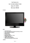
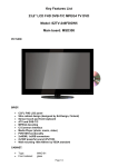
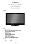
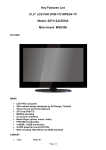
User Manual ARK-1380 Ultra Compact, Intel® ULV Celeron® M 1 GHz with PC Card Slot, 4 x USB, CRT & LVDS, 1 x LAN, 2 x COM, Fanless Embedded Computer Copyright The documentation and the software included with this product are copyrighted 2007 by Advantech Co., Ltd. All rights are reserved. Advantech Co., Ltd. reserves the right to make improvements in the products described in this manual at any time without notice. No part of this manual may be reproduced, copied, translated or transmitted in any form or by any means without the prior written permission of Advantech Co., Ltd. Information provided in this manual is intended to be accurate and reliable. However, Advantech Co., Ltd. assumes no responsibility for its use, nor for any infringements of the rights of third parties, which may result from its use. Acknowledgements Intel® and Pentium® are trademarks of Intel Corporation. Microsoft Windows® and MS-DOS are registered trademarks of Microsoft Corp. All other product names or trademarks are properties of their respective owners. Product Warranty (2 years) Advantech warrants to you, the original purchaser, that each of its products will be free from defects in materials and workmanship for two years from the date of purchase. This warranty does not apply to any products which have been repaired or altered by persons other than repair personnel authorized by Advantech, or which have been subject to misuse, abuse, accident or improper installation. Advantech assumes no liability under the terms of this warranty as a consequence of such events. Because of Advantech’s high quality-control standards and rigorous testing, most of our customers never need to use our repair service. If an Advantech product is defective, it will be repaired or replaced at no charge during the warranty period. For outof-warranty repairs, you will be billed according to the cost of replacement materials, service time and freight. Please consult your dealer for more details. If you think you have a defective product, follow these steps: 1. Collect all the information about the problem encountered. (For example, CPU speed, Advantech products used, other hardware and software used, etc.) Note anything abnormal and list any onscreen messages you get when the problem occurs. 2. Call your dealer and describe the problem. Please have your manual, product, and any helpful information readily available. 3. If your product is diagnosed as defective, obtain an RMA (return merchandise authorization) number from your dealer. This allows us to process your return more quickly. 4. Carefully pack the defective product, a fully-completed Repair and Replacement Order Card and a photocopy proof of purchase date (such as your sales receipt) in a shippable container. A product returned without proof of the purchase date is not eligible for warranty service. 5. Write the RMA number visibly on the outside of the package and ship it prepaid to your dealer. ARK-1380 User Manual Part No. 2006138000 Edition 1 Printed in China December 2007 ii Declaration of Conformity FCC Class A This device complies with the requirements in part 15 of the FCC rules: Operation is subject to the following conditions: 1. This device may not cause harmful interference, and 2. This device must accept any interference received, including interference that may cause undesired operation. This equipment has been tested and found to comply with the limits for a Class A digital device, pursuant to part 15 of the FCC Rules. These limits are designed to provide reasonable protection against harmful interference when the equipment is operated in a commercial environment. This equipment generates, uses, and can radiate radio frequency energy and, if not installed and used in accordance with the instruction manual, may cause harmful interference to radio communications. Technical Support and Assistance 1. 2. Visit the Advantech web site at www.advantech.com/support where you can find the latest information about the product. Contact your distributor, sales representative, or Advantech's customer service center for technical support if you need additional assistance. Please have the following information ready before you call: – Product name and serial number – Description of your peripheral attachments – Description of your software (operating system, version, application software, etc.) – A complete description of the problem – The exact wording of any error messages Warnings, Cautions and Notes Caution! There is a danger of a new battery exploding if it is incorrectly installed. Do not attempt to recharge, force open, or heat the battery. Replace the battery only with the same or equivalent type recommended by the manufacturer. Discard used batteries according to the manufacturer's instructions. Packing List Before installation, please ensure the following items have been shipped: Item Part Number – 1 ARK-1380 unit – 1 Utility CD – 1 Registration and 1 year Warranty card Rev. A – 2-Pole Phoenix to DC-Jack Power Cable 1700001394 – DB-9 Male to Mic_In, Ln_Out and Ln_In Audio Cable 1700006011 iii ARK-1380 User Manual Ordering Information Model Number Description ARK-1380-1S0A1E Intel ULV Celeron M 1GHz, 2 x Serial ports, PCMCIA,1 x LAN, 4 x USB 2.0, 2 x COM, 1 x VGA, 1 x LVDS,Ultra Compact, Fanless Embedded Box Computer ARK-1380-2S0A1E ARK-1380-1S0A1E with 512 MB DDR SDRAM, 1 GB Compact Flash Disk, pre-installed Windows CENET 5.0 Professional Plus and License ARK-1380-1M0A1E Intel Celeron M 600MHz, 2 x Serial ports, PCMCAI, 1 x LAN, 4 x USB 2.0, 2 x COM, 1 x VGA, 1 x LVDS, Ultra Compact, Fanless Embedded Computer ARK-1380-2M0A1E ARK-1380-1M0A1E with 512 MB DDR SDRAM,1GB Compact Flash Disk, pre-installed Windows XP, Embedded FP2007 OS Image and License Optional Accessories 1757000222 AC-to-DC Adapter DC19 V/3.42 A 65 W, with Phoenix Power Plug, 0 ~ 40° C for Home and Office Use 1700060202 PS2 Keyboard/Mouse Cable 1960008516 VESA mounting plate 1700001947 Power Cable 2-pin 180 cm, USA type 1700001948 Power Cable 2-pin 180 cm, Europe Type 1700001949 Power Cable 2-pin 180 cm, UK Type 1997001110 1997001120 Din-Rail Mounting Kit 1997001130 1997001140 ARK-1380 User Manual iv Contents Chapter 1 General Introduction ...........................1 1.1 1.2 Introduction ............................................................................................... 2 Product Features....................................................................................... 3 1.2.1 General ......................................................................................... 3 1.2.2 Display .......................................................................................... 3 Specifications ............................................................................................ 4 1.3.1 Functional Specifications .............................................................. 4 Table 1.1: Processor ................................................................... 4 Table 1.2: Chipset ....................................................................... 4 Table 1.3: Others (Chipset) ......................................................... 6 1.3.2 Mechanical Specifications............................................................. 7 Figure 1.1 Product Specifications ................................................ 7 1.3.3 Electrical Specifications ................................................................ 7 1.3.4 Environmental Specifications........................................................ 8 1.3 Chapter 2 H/W Installation....................................9 2.1 2.2 Introduction ............................................................................................. 10 Jumpers .................................................................................................. 10 2.2.1 Jumper Description ..................................................................... 10 2.2.2 Jumper List and Settings ............................................................ 11 Connectors.............................................................................................. 12 Figure 2.1 ARK-1380 Front I/O Panel........................................ 12 Figure 2.2 ARK-1380 Rear I/O Panel ........................................ 12 ARK-1380 Front Side External I/O Connectors....................................... 13 2.4.1 COM Connector .......................................................................... 13 Figure 2.3 COM connector ........................................................ 13 Table 2.1: COM Standard Serial Port Pin Assignments ............ 13 2.4.2 USB Connectors ......................................................................... 14 Figure 2.4 USB Connector......................................................... 14 Table 2.2: USB Connector......................................................... 14 2.4.3 PS2 Keyboard/Mouse Connector ............................................... 15 Figure 2.5 PS/2 Connector ........................................................ 15 Table 2.3: PS/2 Keyboard/Mouse Connector Pin Assignments 15 2.4.4 Ethernet Connector (LAN) .......................................................... 16 Figure 2.6 Ethernet connector ................................................... 16 Table 2.4: RJ-45 Connector Pin Assignments........................... 16 ARK-1380 Rear Side External I/O Connectors ....................................... 17 2.5.1 Power ON/OFF Button................................................................ 17 2.5.2 LED Indicators ............................................................................ 17 2.5.3 LVDS Connector ......................................................................... 17 Figure 2.7 LVDS Connector....................................................... 17 Table 2.5: LVDS Connector Pin Assignment............................. 17 2.5.4 PCMCIA Expansion Slot ............................................................. 17 2.5.5 AUDIO Connector ....................................................................... 18 Figure 2.8 Audio connector........................................................ 18 Table 2.6: Audio Connector Pin Assignment............................. 18 2.5.6 VGA Connector........................................................................... 19 Figure 2.9 VGA connector ......................................................... 19 Table 2.7: VGA Connector Pin Assignment .............................. 19 2.5.7 Power Input Connector ............................................................... 19 Figure 2.10Power Input Connector............................................. 19 Table 2.8: Power Connector Pin Assignments .......................... 19 Dimension ............................................................................................... 20 2.3 2.4 2.5 2.6 v ARK-1380 User Manual Figure 2.11Dimension ................................................................ 20 Chapter 3 BIOS Operation ................................. 21 3.1 3.2 BIOS Introduction.................................................................................... 22 BIOS Setup ............................................................................................. 22 3.2.1 Main Menu .................................................................................. 23 3.2.2 Standard CMOS Features .......................................................... 24 3.2.3 Advanced BIOS Features ........................................................... 25 3.2.4 Advanced Chipset Features ....................................................... 26 3.2.5 Integrated Peripherals ................................................................ 27 3.2.6 Power Management Setup ......................................................... 28 3.2.7 PnP/PCI Configurations.............................................................. 29 3.2.8 PC Health Status ........................................................................ 29 3.2.9 Frequency/Voltage Control ......................................................... 30 3.2.10 Load Optimized Defaults ............................................................ 30 3.2.11 Set Password.............................................................................. 30 3.2.12 Save & Exit Setup....................................................................... 31 3.2.13 Quit Without Saving .................................................................... 31 4 Full Disassembly Procedure............ 33 4.1 Introduction ............................................................................................. 34 Figure 4.1 Unscrew the 4 screws on the bottom side................ 34 Figure 4.2 Unscrew the 6 screws on the front side frame ......... 35 Figure 4.3 Unscrew the 4 Hex-bolt on the front face plate ........ 35 Figure 4.4 Unscrew the 6 screws on the rear side frame .......... 36 Figure 4.5 Unscrew the 6 Hex-bolt on the rear face plate ......... 36 Figure 4.6 Pull out the carrier board from the aluminum case... 37 Figure 4.7 Remove the CF card anti-shock holder.................... 37 Figure 4.8 Remove the CF card ................................................ 38 Figure 4.9 Turn over the carrier board and remove the DRAM module...................................................................... 38 Appendix A Intel Boot Agent Setup Menu........... 41 A.1 Intel Boot Agent Setup Menu .................................................................. 42 Chapter ARK-1380 User Manual vi Chapter 1 1 General Introduction This chapter gives background information on the ARK-1380. Sections include: Introduction Specifications 1.1 Introduction Advantech provides the smallest compact embedded computers on the market --the ARK-1300 series. These small, powerful all-in-one fanless systems are designed for rugged and space critical applications in automation control and wireless gateway applications. A solid sealed aluminum case provides vibration and water resistance while also providing a passive cooling solution. The ARK-1380 provides system integrators with a turn-key solution and versatile application development path without breaking the bank or missing time to market deadlines The ARK-1380 can be used as a standalone system, wall-mounted, DIN-rail mounted or VESA mounted. The system accepts a wide range of power supplies (DC power in) and comes in a footprint of only 189 x 41 x 136.5 mm (7.44" x 1.61" x 5.37"). The rugged cast aluminum case not only provides great protection from EMI, shock/vibration, cold and heat, but also passive cooling for quiet fanless operation. The ARK-1380 answers this demand by offering 4 x USB 2.0 ports, 1 x LVDS interface, 1 x LAN port and 2 x COM ports; packed into a small rugged unit and powered by an Intel Celeron M processor. Wireless connectivity can be added via the PC card slot for PCMCIA or CardBus cards. It also supports a wide range of input voltages from 9 VDC to 35 VDC. The ARK-1380 Compact Embedded Computer is equipped with a solid state onboard CF card of up to 8 GB, so it easily passes 50 and 5 Grms shock and vibration tests. ARK-1380 User Manual 2 1.2.1 General CPU: Intel Celeron M 1.0 GHz/ Celeron M 600 MHz System Chipset: 855 GME/852 GM SSD: Supports CompactFlash® Card TYPE I/II (shared 1st IDE Channel) Watchdog Timer: Single chip Watchdog 255-level interval timer, setup by software Expansion Interface: 1 x built-in PC Card that support Card-Bus (Card-32) and 16 bit (PCMCIA 2.1/JEIDA 4.2) cards 5 V and 3.3 V working power Battery: 3 V/210 mAh I/O Interface: 1 x KB/mouse, 2 x RS232/422/485 (by BIOS select) USB: 4 x USB 2.0 compliant Ports Audio: ALC203 AC97 surround stereo sound and dual output 2.2W amplifier. Supports Line -in, Line-out, Microphone-in IrDA: N/A LAN Chipset: Intel 82551QM Speed: 10/100 Mbps Interface: 1 x RJ45 Standard: IEEE 802.3u 100Base-T 1.2.2 Display Chipset: Intel 855GME/852GM integrated chip. (Extreme Graphics 2) Memory Size: Optimized Shared Memory Architecture, supports up to 64 MB frame buffer using system memory Resolution: CRT Display mode: pixel resolution up to 1600 x 1200 at 85 Hz and 2048 x 1536 at 75 Hz LCD Display mode: Dual channel LVDS panel supports up to UXGA panel resolution with frequency range from 25 MHz to 112 MHz LCD Interface: 1 Channel, 1 x 18/36-bit LVDS LVDS: one Hirose connector supports up to 2 channels LVDS LCD Panel Dual Independent Display: CRT + LVDS 3 ARK-1380 User Manual General Introduction BIOS: AWARD® 4 Mbit Flash BIOS System Memory: 200-pin SODIMM socket, support ECC Double Data Rate (DDR) 128 MB to 1 GB, accept 128/256/512/1 GB DDR 266/333 DRAM Power Management: APM1.2, ACPI support Chapter 1 1.2 Product Features 1.3 Specifications 1.3.1 Functional Specifications 1.3.1.1 Processor Table 1.1: Processor For ARK-1380-1S0A1E and ARK-1380-2S0A1E Processor CPU support Supports 400 MHz Source-Synchronous Processor System Bus Supports Celeron M-1.0GHZ (373) CPU 35 mm *35 mm Micro-FCBGA Package For ARK-1380-1M0A1E and ARK-1380-2M0A1E Processor CPU support Supports 400 MHz Source-Synchronous Processor System Bus Supports Celeron M-600MHz CPU 35 mm *35 mm Micro-FCBGA Package 1.3.1.2 Chipset Table 1.2: Chipset Memory Intel 82855GME/ICH4 chip support Supports DDR 200/266/333 SDRAM Supports maximum 1GB DDR SDRAM Socket: SO-DIMM Socket: 1. Graphic and Video Controllers 200 pin SO-DIMM socket type *1 (internal) Intel 82855GME/ICH4 chip support DuoView+TM Capability Dual display: CRT+LVDS WinXP, Extended desktop support LVDS Panel Display Interface Supports panel resolution from VGA through UXGA (1600x1200) Supports 1 x 18/36 bit CRT Supports CRT resolutions up to 2048x1536 Analog CRT Connector: D-sub 15-pin 5 mm (Black) ARK-1380 User Manual 4 SSD Intel 82855GME/ICH4 chip support Supports Compact Flash Card Type I/II Socket: 50 pin Compact Flash Card Type 1 connector (Internal) HD Audio Link Intel 82855GME/ICH4 controller chip support AC97 2.0 complain Support Line in, line out, Mic-in Intel 82855GME/ICH4 controller chip support Four USB 2.0 ports Legacy keyboard and PS/2 mouse support USB Connector: USB conn 8P 90D(M) x 2 Power Management Intel 82855GME/ICH4 controller chip support BIOS Supports both ACPI (Advanced Configuration and Power Interface) 2.0 and legacy APM V1.2 power management Intel 82855GME/ICH4 chip supports Phoenix 4M bit Flash BIOS, supports Plug & Play, APM 1.2/ACPI 1.1 FWH Type Socket: 32 pin PLCC socket 5 ARK-1380 User Manual General Introduction Connectors: D-SUB Conn. 9-pin USB Interface Chapter 1 Table 1.2: Chipset 1.3.1.3 Others (Chipset) Table 1.3: Others (Chipset) Serial Ports Super I/O: Winbond W83627HF support Thermal Sensor 2 full function serial ports by Winbond W83627. Supports IRQ Sharing among serial ports on XPE COM1: Supports to RS-232/422/485 and setting by BIOS COM2: Supports to RS-232/422/485 and setting by BIOS COM connector: D-SUB CON. 9P 90D (M) DIP x 2 Super I/O: Winbond W83627HF support Monitor the current CPU temperature Monitor the main power voltage Keyboard/Mouse Connectors Super I/O: Winbond W83627HF support LAN LAN Connector: Intel 82562GZ support Audio PS/2 Keyboard and Mouse interface. PS/2 Connector: MINIDIN 6P Short body W/ Shielding90D (F) DIP x 1 IEEE 802.3 10BASE-T/100BASE-TX compliant physical layer interface IEEE 802.3u Auto-Negotiation support LAN connector: Phone Jack RJ45 8P8C 90D W/LED x 1 Audio Codec: Realtek ALC203 Amplifier: National LM4863 PCI CARDBUS Compliant with AC97 2.3 specifications Supports up to 20-bit DAC and 18-bit ADC resolution Dual 2.2W Audio Amplifier Plus Stereo Headphone for LINE-OUT Supports MIC and LINE-IN Audio Connector on board: D-SUB Conn. 9P 90D (F) DIP Utra-Slim x 1 Audio Extended Cable x 1 PCI Card bus Bridge: RICOH R5C485 ACPI and PCI Bus Power Management 1.1 compliant Compliant with PCI Local Bus Specification2.2 Supports Card Bus (Card-32) Card and 16-bit (PCMCIA2.1/JEIDA4.2) Card Bridge function between PCI bus and Card Bus Supports 1 PC Card Socket PCMCIA Socket on board: PCMCIA 68P 90D (F) SMD x 1 Battery Backup Battery support: CR2032 ARK-1380 User Manual BATTERY 3V/210 mAh with WIRE x 1 6 PCMCIA VGA HDD AUDIO LVDS PWR ON/OFF GND Detail A 5.1 14.4 8,0 Ø4,6 165,0 3,8 COM2 LAN PS/2 USB3 USB4 189,0 41,0 USB1 USB2 3,6 COM1 Figure 1.1 Product Specifications 1.3.2.1 Dimension (mm) (W) 189 x (H) 41 x (D) 136.5 (7.44" x 1.61" x 5.37") 1.3.2.2 Weight (g) 1 Kg 1.3.3 Electrical Specifications 1.3.3.1 Voltage Requirement with Adaptor 9 V-3.8 A ~ 35 V-1 A Adaptor 1.3.3.2 Supply Current Supply Current (Maximum) CPU: Celeron M-1.0G (373), RAM: 333 MHz 512GB DDR SDRAM Adaptor 19 V Dos NC BIOS 1.98 A WINXP Idle 2.18 A WINXP HCT11.0 NC WINXP 3DMARK2001SE NC WINXP BURN IN TEST 2.2 A 7 ARK-1380 User Manual General Introduction 78,8 VCC 140,0 DC IN 9V~35V Chapter 1 1.3.2 Mechanical Specifications Supply Current (Maximum) CPU: Celeron M-600M, RAM: 333 MHz 512GB DDR SDRAM Adaptor 19 V Dos NC BIOS 1.81 A WINXP Idle 2A WINXP HCT11.0 NC WINXP 3DMARK2001SE NC WINXP BURN IN TEST 2A 1.3.3.3 RTC Battery Nominal Voltage: 3.0 V Nominal discharge capacity: 210 mAh 1.3.4 Environmental Specifications 1.3.4.1 Operating Temperature The Intel Celeron is specified for proper operation when the junction temperature is within the specified range of 0° C to 100° C. The Intel 855GME/852GM chipset temperature runs at a maximum of 100° C. The Intel ICH4 I/O Controller Hub 4 (82801DB) case temperature runs at a maximum of 110° C. The processor protects itself from catastrophic overheating by use of an internal thermal sensor at a temperature level of approximately 135° C. Operating temperature: 0° C ~ 60° C 1.3.4.2 Operating Humidity 0% ~ 90% Relative Humidity, non-condensing 1.3.4.3 Storage Temperature Platinum Phoenix products (40° C ~ 75° C) Storage temperature: -40 ~ 85° C 1.3.4.4 Storage Relative Humidity Standard products (0 ~ 60° C) Relative humidity: 95% @ 60° C Phoenix products (-20 ~ 80° C) Relative humidity: 95% @ 60° C Platinum Phoenix products (-40 ~ 85° C) Relative humidity: 95% @ 60° C ARK-1380 User Manual 8 Chapter 2 H/W Installation 2 2.1 Introduction The following two figures show the connectors on the ARK-1380. The following sections give you detailed information about the function of each peripheral. 2.2 Jumpers 2.2.1 Jumper Description You can configure your ARK-1380 to match the needs of your application by setting jumpers. A jumper is the simplest kind of electrical switch. It consists of two metal pins and a small metal clip (often protected by a plastic cover) that slides over the pins to connect them. To “close” a jumper, you connect the pins with the clip. To “open” a jumper you remove the clip. Sometimes a jumper will have three pins, labeled 1, 2, and 3. In this case, you could connect either pins 1 and 2 or pins 2 and 3. The jumper settings are schematically depicted in this manual as follows. 1 2 3 A pair of needle-nose pliers may be helpful when working with jumpers. If you have any doubts about the best hardware configuration for your application, contact your local distributor or sales representative before you make any changes. Generally, you simply need a standard cable to make most connections. ARK-1380 User Manual 10 2.2.2.1 LVDS Power The ARK-1380 embedded box computer provides a jumper - CN14 located on the internal carrier board for selecting an LCD signal power of 5 V or 3.3 V. When you connect your LVDS LCD panel display, you need to set up the CN14 jumper for the LCD power setting selection for your LVDS panel display. Function 1-2 +5 V* 2-3 +3.3 V (*): means default setting of the jumper/function. 2.2.2.2 Clear CMOS The ARK-1380 embedded box computer provide a jumper - CN29 located on the internal carrier board for selecting the CMOS of Clear or Normal status. Close Pins Function 1-2 Clear CMOS 2-3 Normal* (*): means default setting of the jumper/function. 11 ARK-1380 User Manual H/W Installation Close Pins Chapter 2 2.2.2 Jumper List and Settings 2.3 Connectors Figure 2.1 ARK-1380 Front I/O Panel COM1 COM2 USB1 USB3 USB2 USB4 LAN PS/2 Figure 2.2 ARK-1380 Rear I/O Panel External CN4 COM1 CN6 COM2 CN7 VGA Connector CN8 USB1 & USB2 CN9 USB3 & USB4 CN10 LAN (RJ45) CN12 Keyboard & Mouse CN16 Power Connector CN23 Audio Connector CN31 LVDS Connector U27 PCMCIA Socket Others SW1 Power On Switch D25 HD & Power LED Internal CN26 ARK-1380 User Manual CF Socket 12 2.4.1 COM Connector The ARK-1380 provides two D-sub 9-pin connectors, which offer RS-232/422/485 serial communication interface ports. Please see the BIOS settings. Chapter 2 2.4 ARK-1380 Front Side External I/O Connectors 1 2 3 4 5 Figure 2.3 COM connector Table 2.1: COM Standard Serial Port Pin Assignments RS-232 RS-422 RS-485 Pin Signal Name Signal Name Signal Name 1 DCD Tx- DATA- 2 RxD Tx+ DATA+ 3 TxD Rx+ NC 4 DTR Rx- NC 5 GND GND GND 6 DSR NC NC 7 RTS NC NC 8 CTS NC NC 9 RI NC NC Note: NC represents “No Connection”. 13 ARK-1380 User Manual H/W Installation 6 7 8 9 2.4.2 USB Connectors The ARK-1380 provides four USB interface connectors, which give complete Plug & Play and hot swapping for up to 127 external devices. The USB interface is compliant with USB UHCI, Rev. 2.0. The USB interface can be disabled in the system BIOS setup. Please refer to Table. 2.2 for its pin assignments. The USB connectors are used for connecting any device that conforms to the USB interface. Many recent digital devices conform to this standard. The USB interface supports Plug and Play, which enables you to connect or disconnect a device whenever you want, without turning off the computer. 4 3 2 1 Figure 2.4 USB Connector Table 2.2: USB Connector Pin Signal name Pin Signal name 1 VCC 2 USB_data- 3 USB_data+ 4 GND ARK-1380 User Manual 14 The ARK-1380 provides a PS/2 keyboard/mouse connector. A 6-pin mini-DIN connector is located on the front metal face plate of the ARK-1380. The ARK-1380 comes with an adapter to convert from the 6-pin mini-DIN connector to two 6-pin mini-DIN connectors for PS/2 keyboards and PS/2 mouse connections. Please refer to Table 2.3 for its pin assignments. 6 5 3 2 1 Figure 2.5 PS/2 Connector Table 2.3: PS/2 Keyboard/Mouse Connector Pin Assignments Signal name 1 PS2_KBDAT 2 PS2_MSDAT 3 GND 4 VCC 5 PS2_KBCLK 6 PS2_MSCLK 15 ARK-1380 User Manual H/W Installation 4 Pin Chapter 2 2.4.3 PS2 Keyboard/Mouse Connector 2.4.4 Ethernet Connector (LAN) The ARK-1380 is equipped with an Intel 82551QM Ethernet controller that is fully compliant with IEEE 802.3u, 10/100Base-T CSMA/CD standards. The Ethernet port provides a standard RJ-45 jack connector with LED indicators on the front side to show its Active/Link status (Green LED) and Speed status (Yellow LED). 1 8 Figure 2.6 Ethernet connector Table 2.4: RJ-45 Connector Pin Assignments Pin 10/100BaseT Signal Name 1 TX+ 2 TX- 3 RX+ 4 NC 5 NC 6 RX- 7 NC 8 NC ARK-1380 User Manual 16 2.5.1 Power ON/OFF Button The ARK-1380 comes with a Power On/Off button, that support a dual function of Soft Power -On/Off (Instant off or Delay 4 Second), and Suspend. 2.5.2 LED Indicators 2.5.3 LVDS Connector The ARK-1380 comes with a D-Sub 26-pin connector that carries LVDS signal output, and can direct connect to an LVDS LCD Display via external cable. The system also provides a jumper, CN14, on the internal motherboard for selecting the LCD signal power of 5 V or 3.3 V. Please refer to section 2.1.2 for the CN14 jumper table, and Chapter 6, “Full Disassembly Procedure” to set it. Up. The default setting of the CN14 is 5 V. Figure 2.7 LVDS Connector Table 2.5: LVDS Connector Pin Assignment Pin Signal Name Pin Signal name 1 CLK2P 14 CLK2M 2 GND 15 A0M 3 A0P 16 A1M 4 A1P 17 A2M 5 A2P 18 CLK1M 6 CLK1P 19 GND 7 VCC_LCD 20 VDD_LCD 8 GND 21 A3M 9 A3P 22 A4M 10 A4P 23 A5M 11 A5P 24 A6M 12 A6P 25 A7M 13 A7P 26 GND 2.5.4 PCMCIA Expansion Slot The ARK-1380 comes with a PCMCIA slot for PC card expansion. 17 ARK-1380 User Manual H/W Installation There are two LEDs on the ARK-1380 front metal face plate for indicating system status: the PWR LED for power status which flashes in green; and the HDD LED for hard disk and compact flash disk status which flashes in red. Chapter 2 2.5 ARK-1380 Rear Side External I/O Connectors 2.5.5 AUDIO Connector The ARK-1380 provides a D-sub 9-pin connector, which offers an AC97 stereo audio output port. There are connections for Speaker_Out, Mic_In and Line_In (The connector can be attached to 3 phone jacks by an audio cable, P/N:1700006011, which is an accessory). 1 2 3 4 5 6 7 8 9 Figure 2.8 Audio connector Table 2.6: Audio Connector Pin Assignment Pin Signal name 1 SPKR 2 GND 3 MIC2 4 LIN_R 5 GND 6 SPKL 7 NC 8 GND 9 LIN_L ARK-1380 User Manual 18 The ARK-1380 provides a high resolution VGA interface connected by a D-sub 15pin connector to support a VGA CRT monitor. It supports display resolution of up to 1600 x 1200 @ 75-Hz and up to 64 MB shared memory. 1 5 11 H/W Installation 15 Figure 2.9 VGA connector Table 2.7: VGA Connector Pin Assignment Pin Signal name 1 Red 2 Green 3 Blue 4 NC 5 GND 6 GND 7 GND 8 GND 9 NC 10 GND 11 NC 12 NC 13 H-SYNC 14 V-SYNC 15 NC 2.5.7 Power Input Connector The ARK-1380 comes with a two pin header that carries and external power input of 9~35 VDC. Figure 2.10 Power Input Connector Table 2.8: Power Connector Pin Assignments Pin Signal Name 1 GND 2 +9~35VDC 19 Chapter 2 2.5.6 VGA Connector ARK-1380 User Manual 78,8 140,0 2.6 Dimension Detail A 5.1 14.4 8,0 Ø4,6 165,0 3,8 COM2 LAN 189,0 PS/2 USB3 USB4 41,0 USB1 USB2 3,6 COM1 Figure 2.11 Dimension ARK-1380 User Manual 20 Chapter 3 BIOS Operation 3 3.1 BIOS Introduction Advantech provides AwardBIOS 6.0, a full-featured BIOS that delivers superior performance, compatibility and functionality; used by manufacturers of industrial PC and embedded boards. Its many options and extensions let you customize your products for a wide range of designs and target markets. The modular, adaptable AwardBIOS 6.0 supports the broadest range of third-party peripherals and all popular chipsets, such as Intel, AMD, nVidia, and VIA. It supports compatible CPUs ranging from 386 through Pentium, AMD Geode, K7 and K8 (including multiple processor platforms), and VIA Eden C3 and C7 CPUs. You can use Advantech’s utilities to select and install features to suit your designs for customer needs. 3.2 BIOS Setup The ARK-1380 system has built-in AwardBIOS with a CMOS SETUP utility which allows users to configure required settings or to activate certain system features. The CMOS SETUP saves the configuration in the CMOS RAM of the motherboard. When the power is turned off, the battery on the board supplies the necessary power to the CMOS RAM. When the power is turned on, press the <Del> key during the BIOS POST (Power-On Self Test) which will take you to the CMOS SETUP screen. CONTROL KEYS < ↑ >< ↓ >< ← >< → > Move to select item <Enter> Select Item <Esc> Main Menu - Quit without saving changes to CMOS Sub Menu - Exit current page and return to Main Menu <Page Up/+> Increase numeric value or make changes <Page Down/-> Decrease numeric value or make changes <F1> General help, for Setup Sub Menu <F2> Item Help <F5> Load Previous Values <F7> Load Optimized Default <F10> Save all CMOS changes ARK-1380 User Manual 22 Press the <Del> key to enter the AwardBIOS CMOS Setup Utility. The Main Menu will appear on the screen. Use the arrow keys to select among the items and press the <Enter> key to accept or enter the sub-menu. Standard CMOS Features This setup page includes all standard compatible BIOS items. Advanced BIOS Features This setup page includes all Award BIOS enhanced features. Advanced Chipset Features This setup page includes all Chipset configuration features. Integrated Peripherals This setup page includes all onboard peripheral devices. Power Management Setup This setup page includes all Power Management features. PnP/PCI Configurations This setup page includes PnP OS and PCI device configuration. PC Health Status This setup page includes system auto detect, current CPU temperature and main voltage. Frequency/Voltage Control This setup page includes PCI clock detect control and Spread Spectrum. Load Optimized Defaults This setup page includes load system optimized value, and system best performance configuration. Set Password Establish, change or disable password. Save & Exit Setup Save CMOS value settings to CMOS and exit BIOS setup. Exit Without Saving Abandon all CMOS value changes and exit BIOS setup. 23 ARK-1380 User Manual BIOS Operation Chapter 3 3.2.1 Main Menu 3.2.2 Standard CMOS Features Date The date format is <week>, <month>, <day>, <year>. Week From Sun to Sat, determined and displayed by BIOS only Month From Jan to Dec Day From 1 to 31 Year From 1999 through 2099 Time The time format is <hour> <minute> <second>, based on 24-hour time. IDE Primary Master/Slave IDE HDD Auto-Detection. Press the ’Enter’ key for automatic device detection. Video Determines that VGA display support type. EGA/VGA Support VGA color mode CGA 40 Support VGA color mode CGA 80 Support VGA color mode MONO Support VGA mono mode Halt on Determines whether or not the computer stops if an error is detected during power up. All Errors Whenever the BIOS detects a non-fatal error the system stops. No Errors The system boot doesn’t stop for any error. All, But Keyboard The system boot doesn’t stop for a keyboard error; does stop for all other errors. (Default value) All, But Diskette The system boot doesn’t stop for a disk error; does stop for all other errors. All, But Disk/Key The system boot doesn’t not stop for a keyboard or disk error, does stop for all other errors. Base Memory [Show Only] The BIOS POST determines the amount of base (or conventional) memory installed in the system. Extended Memory [Show Only] The BIOS POST determines the amount of extended memory (above 1MB in CPU’s memory address map) installed in the system. Total Memory [Show Only] Displays the total system memory size. ARK-1380 User Manual 24 First [USB-HDD] Second [USB-CDROM] Third [HDD-0] Other [Enabled] HDD-0 Select boot device priority by HDD-0 HDD-1 Select boot device priority by HDD-1 ZIP100 Select boot device priority by ZIP100 USB-FDD Select boot device priority by USB-FDD USB-ZIP Select boot device priority by USB-ZIP USB-CDROM Select boot device priority by USB-CDROM USB-HDD Select boot device priority by USB-HDD LAN Select boot device priority by LAN Disabled Disable this boot function Boot Up NumLock Status [On] Enables users to activate the Number Lock function upon system boot. Gate A20 Option [Fast] Enables users to switch on/off A20 control at port 92. Typematic Rate Setting [Disabled] Enables users to set the two typematic controls items. – Typematic Rate (Chars/Sec) Controls speed of repeated keystrokes at system registers. Eight settings are 6, 8, 10, 12, 15, 20, 24 and 30. – Typematic Delay (Msec) Sets the time interval for displaying the first and second characters. The four delay rate options are 250, 500, 750 and 1000. Security Option [Setup] Setup When you select “Setup”, the system prompts for the supervisor password at boot up only when the setup utility is invoked When you select “System”, the system prompts for the user password every time you boot up. System APIC Mode [Enabled] 25 ARK-1380 User Manual BIOS Operation Blank Boot [Disabled] Allows users to choose a blank screen when the system boots. Post Beep [Enabled] Allows users to enable a beep sound during POST test status. Virus Warning [Disabled] Allows users to choose the VIRUS Warning feature for CF boot sector protection. CPU L1 & L2 Cache [Enabled] Allows user to enable CPU L1 & L2 cache. Quick Power On Self Test [Enabled] Speeds up the Power-On Self Test (POST) routine by skipping retesting a second, third and forth time. Setting is enabled by default. First / Second / Third / Other Boot Drive Chapter 3 3.2.3 Advanced BIOS Features Sets the operating system to enable APCI Mode. MPS Version Control for OS [1.4] Sets operating system multiprocessor support version. OS Select For DRAM > 64M [Non-OS2] Select OS2 only if system is running the OS/2 operating system with more than 64MB of RAM on the system. Full Screen LOGO Show [Enabled] Show full screen logo during POST, customize Logo picture. Small Logo (EPA) Show [Disabled] Show EPA logo during system POST. Summary Screen Show [Enabled] Allows users to choose to display the summary screen on boot up. Options are enable or disable. 3.2.4 Advanced Chipset Features Note! The “Advanced Chipset Features” option controls the configuration of the board’s chipset. It is chipset independent, for controlling chipset register settings and fine tuning system performance. It is strongly recommended that only technical users make changes to the default settings. DRAM Timing Selectable [By SPD] Enables users to set optimal timings. System default setting is “By SPD” which follows SPD information and ensures the system is running stably and performing optimally. CAS Latency Time Enables users to set the timing delay in clock cycles before SDRAM starts a read command after receiving it. Active to Precharge Delay Enables users to control the memory back’s minimum row active time (tRAS). DRAM RAS# to CAS# Delay Enables users to set the timing of the transition from RAS (row address strobe) to CAS (column address strobe), as both rows and column are separately addressed shortly after the DRAM is refreshed. DRAM RAS# Precharge Enables users to set the DRAM RAS# precharge timing. DRAM Data Integrity Mode [Non-ECC] Enables users to set the DRAM Type of Error data correction. System default setting is “Non-ECC” to reference value. MGM Core Frequency [Auto Max 266MHz] Allows the system BIOS to be cached to allow MGM Core Frequency. System BIOS Cacheable [Enabled] Allows the system BIOS to be cached to allow faster execution and better performance. Video BIOS Cacheable [Disabled] Allows the video BIOS to be cached to allow faster execution and better performance. AGP Aperture Size (MB) [64] ARK-1380 User Manual 26 3.2.5 Integrated Peripherals Note! This “Integrated Peripherals” option controls the configuration of the board’s chipset, including IDE, ATA, SATA, USB, AC97, MC97 and Super IO and Sensor devices. It is chipset independent. OnChip IDE Device Enables users to set the OnChip IDE device status, including enabling IDE devices and setting PIO and DMA access mode. Onboard Device Enables users to set the Onboard device status, including enabling USB, AC97, MC97 and LAN devices. Super I/O Device Enables users to set the Super IO device status. – Onboard Serial Port 1 [3F8/IRQ4] Allows users to change the COM1 address and IRQ. BIOS default value: 3F8/IRQ4. – Onboard Serial Port 2 [2F8/IRQ3] Allows users to change the COM2 address and IRQ. BIOS default value: 2F8/IRQ3. – UART Mode Select [Normal] Allows selection for the mode of operation of the serial port. – Onboard Parallel Port [378/IRQ7] Allows users to change the parallel port address. BIOS default value: 378/ IRQ7. – Parallel Port Mode [SPP] Allows users to change the parallel port mode. The user can choose SPP, EPP, ±ECP and ECP+EPP. Definitions: SPP (Standard Parallel Port), ECP (Extended Capabilities Port) and EPP (Enhanced Parallel Port). BIOS default value: Normal. – EPP Mode Select [EPP1.7] Allows users to change the EPP Mode for the parallel port. BIOS default value: EPP1.7. – ECP Mode Use DMA [3] 27 ARK-1380 User Manual BIOS Operation Chapter 3 Enables users to select the size of system memory to support AGP graphic usage. System default setting is “64MB” to reference value. On-Chip VGA [Enabled] Allows the system BIOS to allow On-Chip VGA. On-Chip Frame Buffer Size [32MB] Allows users to choose Frame Buffer Size. BIOS default value is set to 32 MB. Boot Display [CRT] Allows users to choose a screen display type. BIOS default value is set to CRT. Panel Scaling [Auto] Allows users to choose Panel Scaling type. BIOS default value is set to Auto. Panel Resolution [800X600] Allows users to choose Panel Resolution. BIOS default value is set to 800 X 600. This item allows the user to change the DMA channel for the parallel port. The BIOS default value is set to 3. Onboard Serial Port 1 Mode [RS232] Sets the mode of serial port 1. Supports RS232/RS422/RS485. BIOS default value is set to RS232. Onboard Serial Port 2 Mode [RS232] Sets the Mode of serial port 2. Supports RS232/RS422/RS485. BIOS default value is set to RS232. 3.2.6 Power Management Setup Note! The “Power management Setup” option configures the system to most effectively save energy while operating in a manner consistent with your style of computer use. Power-Supply Type [ATX] Allows users to select power supply type. ACPI Function [Enabled] Defines the ACPI (Advanced Configuration and Power Management) feature that makes hardware status information available to the operating system, and communicates to PC and system devices for improving power management. ACPI Suspend Type [S1 (POS)] Allows users to select sleep state when suspended. – S1(POS) Suspend mode is equivalent to a software power down; – S3(STR) System shuts down with the exception of a refresh of current to system memory. – S1 & S3 Support both modes, software selectable. Run VGABIOS if S3 Resume [Auto] Allows system to reinitialize VGA BIOS after system resume from ACPI S3 mode. Power Management Option [User Define] Allows users to select system power saving mode. – Min Saving Minimum power management. Suspend Mode=1 hr. – Max Saving Maximum power management. Suspend Mode=1 min. – User Define Allows users to set each mode individually. Suspend Mode= Disabled or 1 min ~1 hr. Video Off Method [DPMS] Allows users to determine the manner is which the monitor is blanked. – Blank Screen This option only writes blanks to the video buffer. – V/H SYNC+Blank This option will cause system to turn off vertical and horizontal synchronization ports and write blanks to the video buffer. – DPMS Initial display power management signaling. Video Off In Suspend [Yes] Allows users to turn off video when system enters suspend mode. Suspend Type [Stop Grant] Allows users to determine the suspend type. Modem use IRQ [3] ARK-1380 User Manual 28 3.2.7 PnP/PCI Configurations Note! The ”PnP/PCI Configurations” option sets up the IRQ and DMA (both PnP and PCI) bus assignments. Reset Configuration Data [Disabled] Allows users to clear any PnP configuration data stored in the BIOS. Resources Controlled By [Auto (ESCD)] – IRQ Resources Allows users to respectively assign an interrupt type for IRQ-3, 4, 5, 7, 9, 10, 11, 12, 14, and 15. – DMA Resources Allows users to respectively assign an interrupt type for DMA, 0, 1, 3, 5, 6, and 7. 3.2.8 PC Health Status Note! The “PC Health Status” option controls the thermal, fan and voltage status of the board. It is chipset independent. Shutdown Temperature [Disabled] Enables users to set CPU temperature limits, ranging from 60° C to 75° C. 29 ARK-1380 User Manual BIOS Operation Chapter 3 Allows users to determine the IRQ which the MODEM can use. Suspend Mode [Disabled] Allows users to determine the timing of system inactivity. All devices except the CPU will be shut off. Soft-Off by PWR-BTTN [Instant-Off] Allows users to define the function of the power button. – Instant-Off Pressing power button powers off instantly. – Delay 4 Sec Pressing power delays power off 4 seconds. Power On by Ring [Enabled] Allows users resume system by modem. USB KB Wake-Up From S3 [Enabled] Allows users to wake the system up from power saving mode using a USB keyboard keystroke. Resume by Alarm [Disabled] Allows users to enable a date/time setting to power on the system – Disabled Disable this function. – Enabled Enable alarm function to power on system – Day (of month) Alarm 1-31 – Resume Time (HH:MM:SS); Alarm (0-23); (0-59); (0-59) PWRON After PWR-Fail [Former-Sts] Allows users to select power fail function. The functions depend on chipset design. Current CPU1 Temperature [Show Only] Displays current system and CPU temperature. Vcc Core / +2.5V / +3.3V / +5V [Show Only] Displays current CPU and system board voltage. 3.2.9 Frequency/Voltage Control Note! The ”Frequency/Voltage Control” option controls the CPU Host and PCI frequency. It is CPU and chipset independent; items will show up if you install a processor which supports this function. Auto Detect PCI Clk [Enabled] Enables users to set the PCI Clock by automatic or manual system detection. Spread Spectrum [Disabled] Enables users to set the spread spectrum modulation. 3.2.10 Load Optimized Defaults Note! Load optimized defaults. loads the default system values directly from ROM if the stored record created by the setup program should ever become corrupted (and therefore unusable). These defaults will load automatically when you turn the ARK-1380 system on. 3.2.11 Set Password Note! To enable this feature, you should first go to the ‘Advanced BIOS Features’ menu, choose the ‘Security Option’, and select either ‘Setup’ or ‘System’, depending on which aspect you want password protected. ‘Setup’ requires a password only to enter ‘Setup’. ‘System’ requires the password either to enter ‘Setup’ or to boot the system. A password may be at most 8 characters long. To Establish Password 1. Choose the ‘Set Password’ option from the CMOS Setup Utility main menu and press the <Enter> key. 2. When you see the ‘Enter Password’ prompt, enter the desired password and press the <Enter> key. 3. At the ‘Confirm Password’ prompt, retype the desired password, then press the <Enter> key. 4. Select ‘Save to CMOS; and ‘EXIT’, type <Y>, then press the <Enter> key. To Change Password 1. Choose the ‘Set Password’ option from the CMOS Setup Utility main menu and press the <Enter> key. 2. When you see the ‘Enter Password’ prompt, enter the existing password and press the <Enter> key. ARK-1380 User Manual 30 3.2.12 Save & Exit Setup Note! Typing “Y” will quit the BIOS Setup Utility and save the user setup value to CMOS. Typing “N” will return to the BIOS Setup Utility. 3.2.13 Quit Without Saving Note! Typing ”Y” will quit the BIOS Setup Utility without saving to CMOS. Typing “N” will return to the BIOS Setup Utility. 31 ARK-1380 User Manual BIOS Operation You will see a ‘Confirm Password’ prompt. Type the password again, and press the <Enter> key. 4. Select ‘Set Password’ again, and at the “Enter Password” prompt, enter the new password and press the <Enter> key. 5. At the ‘Confirm Password’ prompt, retype the new password, and press the <Enter> key. 6. Select ‘Save to CMOS’ and ‘EXIT’, type <Y>, then press the <Enter> key. To Disable Password 1. Choose the Set Password option from the CMOS Setup Utility main menu and press the <Enter> key. 2. When you see ‘Enter Password’, enter the existing password and press the <Enter> key. 3. You will see ‘Confirm Password’. Type it again, and press the <Enter> key. 4. Select ‘Set Password’ again, and at the “Enter Password” prompt, please don’t enter anything; just press the <Enter> key. 5. At the ‘Confirm Password’ prompt, again, don’t type in anything; just press the <Enter> key. 6. Select ‘Save to CMOS’ and ‘EXIT’, type <Y>, then press the <Enter> key. Chapter 3 3. ARK-1380 User Manual 32 Chapter 4 Full Disassembly Procedure 4 4.1 Introduction If you want to completely disassemble the ARK-1380, follow the step-by-step procedures below. Users should be aware that Advantech Co., Ltd. takes no responsibility whatsoever for any problems or damage caused by user disassembly of the ARK1380. Make sure the power cord of the ARK-1380 is unplugged before you start disassembly. 1. Unscrew the 4 screws on the bottom side. Figure 4.1 Unscrew the 4 screws on the bottom side ARK-1380 User Manual 34 Unscrew the 6 screws on the front side frame. 3. Figure 4.2 Unscrew the 6 screws on the front side frame Unscrew the 4 Hex-bolts on the front face plate. Chapter 4 2. 4. Unscrew the 6 screws on the rear side frame. 35 ARK-1380 User Manual Full Disassembly Procedure Figure 4.3 Unscrew the 4 Hex-bolt on the front face plate Figure 4.4 Unscrew the 6 screws on the rear side frame 5. Unscrew the 6 Hex-bolts on the rear face plate. Figure 4.5 Unscrew the 6 Hex-bolt on the rear face plate ARK-1380 User Manual 36 Pull out the carrier board from the Aluminum case. Chapter 4 6. 7. Remove the CF card anti-shock holder. Figure 4.7 Remove the CF card anti-shock holder 37 ARK-1380 User Manual Full Disassembly Procedure Figure 4.6 Pull out the carrier board from the aluminum case 8. Remove the CF card. Figure 4.8 Remove the CF card 9. Turn over the carrier board, remove the DRAM module. Figure 4.9 Turn over the carrier board and remove the DRAM module ARK-1380 User Manual 38 Before installing the system, please make sure the thermal pad is not broken and be careful of the thermal pad when you insert the board into the system. Chapter 4 Note! Full Disassembly Procedure 39 ARK-1380 User Manual ARK-1380 User Manual 40 Appendix A A Intel Boot Agent Setup Menu A.1 Intel Boot Agent Setup Menu This appendix allows the user to control the ‘Boot Agent Setup’ menu. 1. To boot the system from a LAN application, hold down the ‘Ctrl + S’ keys during system initialization to enter the ‘Boot Agent Setup’ menu. 2. The Intel Boot Agent provides a choice of two network boot protocols (PXE and RPL) that a user can select from the ‘Network Boot Protocol’ item. 3. To show the prompt message, hold down the ‘Ctrl + S’ keys during system initialization to enter the ‘Boot Agent Setup’ menu and select ‘Show Setup Prompt’ item. ARK-1380 User Manual 42 Appendix A Intel Boot Agent Setup Menu ARK-1380 User Manual 43 www.advantech.com Please verify specifications before quoting. This guide is intended for reference purposes only. All product specifications are subject to change without notice. No part of this publication may be reproduced in any form or by any means, electronic, photocopying, recording or otherwise, without prior written permission of the publisher. All brand and product names are trademarks or registered trademarks of their respective companies. © Advantech Co., Ltd. 2007