1
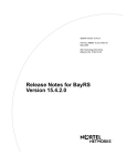
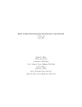
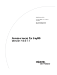
+5,
T ECH TALK
VOLUME #8
JUNE 1999
COMMUNICATION SYSTEMS DIVISION
TECH SUPPORT NEWSLETTER
THE NEW KX-T7885
900MHz
M ul t i - L i ne Wirele s s Te le p h o n e
· 12 Flexible CO Keys
· Built-In Headset Jack
· NiMH Battery
3 Line Display
· Lighted Display
· Two Color Led Buttons
· Belt Clip
Caller ID Compatible*
· Adjustable Ring Modes
And It Vibrates Too!!
Watch Your Mailbox For More Details
+5,
TECHNICA L S T U F F
The new KX-T7885
will soon be arriving
at your distributor’s doorstep. With this new 900
MHz Multi-Line Wireless telephone, your customers
will not have to wait at their desks for those important phone calls! This new phone will give them the
mobility and clarity of 900 MHz operation, plus the
functionality of a powerful system phone. Just clip
the compact handset to your belt and your ready to
take and make calls from anywhere within range. It
possesses host of sophisticated features that you can
control with the handset’s flexible keys and function
buttons. A 3-line LCD display helps make it easy to
use and the built-in headset jack lets you connect an
optional hands-free headset.
**The KX-T7885 works on All KX-T Telephone Systems**
Remember....The new KX-T7885 can be wired straight to an outside line, but will only display Caller ID when the phone is
in the EMSS mode and connected to one of our KX-T systems that supports Caller ID (with optional card) and the Caller ID
service is enabled from the service provider.
Our new KX-T7440 DSS Console has 66 programmable buttons on it. In order to program the buttons,
using the laptop, you have to enter the appropriate DSS console screen, which looks like the one below.
How do you get to keys 33-66? As you can see here you have to hit the F3 button. This will take you to the
next screen where you can modify those buttons.
DSS13 DSS
:EXT[113 ] DSS29
DSS14 DSS
:EXT[114 ] DSS30
DSS15 DSS
:EXT[115 ] DSS31
DSS16 DSS
:EXT[116 ] DSS32
Hit spacebar to select parameter
1 DSS 2 COPY 3 33- 66 4 HELP
DSS
DSS
DSS
DSS
:EXT[129
:EXT[130
:EXT[131
:EXT[132
]
]
]
]
PF13
PF14
PF15
PF16
[
[
[
[
5 P-PAGE 6 N-PAGE 7 SAVE
]
]
]
]
8 EXIT
T he f ol l owi ng ques tion is on e of th e mo s t fre qu e n tly a s k e d : M y cu s tome r h a s a D i g i t a l s y s tem. H e / she al so h as Call Waitin g from te lco. W h e n th e y a re o n a ca ll a n d th e y re c e i v e a c a l l
wa i t i n g tone, t hey h it th e flas h button on th e ir te le p h on e a n d th e y g e t th e s e con d ca l l , b ut t he y
d rop t he f i r st cal l er. Is th ere
any p ro g r am mi ng t hat will
Additional Function
¦ Off-line
¦ KX-TD1232 Master
prev e nt thi s?
-------------------------------------------------------------------------------In p ro g r a m # 9 9 0 ,
FNC
16 15 14 13 12 11 10 9 8 7 6 5 4 3 2 1
( A d d i t i o n al Fu nct i on s ) s ys 01
S Y S 01 0 0 1 0 1 0 0 0 1 1 0 0 0 1 0 1
co l um n 3 ( Fi el d 03) , h as to be
S
Y S 02 1 1 1 0 0 1 1 0 0 0 1 0 1 1 0 0
chan g e d f rom a “0” to a “1”.
S Y S 03 0 0 0 0 0 0 0 0 0 0 0 0 0 0 0 0
I f t h e re i s a “0” i n th is locaS Y S 04 1 1 1 1 1 1 1 1 0 0 0 0 0 0 0 0
tio n , i t m eans di scon n ec t. If
y ou c h a n ge i t t o “1 ” th en it
l o o k s a t y o u r F l a s h Ti m e r ( P ro g r a m # 4 1 3 t o s e e h o w l o n g o f a f l a s h i t s h o u l d p e r f o r m . I n m o s t
ca se s 6 0 0 ms i s w hat your telc o will be loo k in g for. T h is is a s n a p s h ot o f p a rt of th e “ A d d i t i o na l
F u nc t i o n s” screen. Here it s h ows wh ich b it h a s to be ch a n g e d .
+5,
T EC HNICA L S T U F F
Let’s talk a little bit about Dpits integration
between one of the Digital systems and one of the TVS
Voice Mail systems. When you use Inband Integration,
you must put the voice mail ports into their own Call
Hunting Group and then go into “System, Misc.” and
program that group as “A”for Auto Attendant or “V” for
Voice Mail, as shown here in this snapshot of part of the
Misc. screen.
Local Access
=>
Call Hunting
=>
PRIORITY = 1
TRG No. = [ 1 ]
EXG No.
1
D
2
[2]
3
[3]
2
V
3
A
system automatically treats them as “Auto Attendant”
ports.
You will be in a screen that looks like the one below.
See the column marked EXG? This is where you can set
up the different Voice Mail groups, or you can leave them
all in the same group so they hunt to each other. In this
example the 4 VM ports are put into 3 different groups.
165 and 166 are in group 1 and will hunt to each other. 167
and 168 are in groups 2 and 3 respectively, by themselves.
If we left all 4 ports in EXG group 1 then they would all
hunt to each other. The setup shown can be used for a
customer who wants certain CO Trunks to be answered
differently. Just DIL 1:1 the CO trunks to the separated
VM ports and have each port set to answer with a
different Company or Custom Service Greeting.
Now, VERY IMPORTANT, when using DPits, DO
NOT, repeat, DO NOT assign any of the Extension
Groups to “A” or “V”!!! If you do, make sure to have an
ample supply of aspirin handy, cause you will need them.
Your head will be spinning trying to figure out why the
system is acting so strangely. The lights on the phones
will act weird, and your Voice Mail might have problems
transferring calls. It might tell the callers that they are
dialing invalid extensions, or it will say that it is transferring calls to the extensions, but the extensions will not
ring.
The correct way to assign DPits Integration is to enter
the E1232A program and go to System (3), Voice Mail
Integration (11), and enter the jack numbers of the ports
that are connected to the TVS system. At that point the
This is only an example. In most cases, one Voice Mail
port per group will not be enough for proper call coverage and is not recommended.
Panasonic recently introduced our latest system,
the KX-TA624. A perfect system for the home, home
office, and small business markets.
We also recently mailed out, to all of our certified dealers, an Interactive Study Guide/CD-ROM
kit, designed to provide the professional installer
with the necessary information needed to successfully install a KX-TA624 system. It is not intended
for the inexperienced do-it-yourselfer, or to replace
the Installation and User Manuals. It is intended to
be used in conjunction with other documentation
provided with the system.
This interactive CD-ROM guides the installer
through the setup and installation, programming,
and the usage of the system.
We think this training CD will be informative
and beneficial to both your technicians and salespersons alike, giving them all the information needed to sell and install the new KX-TA624 Advanced
Hybrid System.
VND Inc. now has these kits available to you at a special
low price of just $25.00. (Part# KX-TA624TK) You
can always reach VND, Inc. at Tel.# 888-201-4030, or
Fax# 888-201-4033.
VM PORT NO.
MASTER
MASTER [ 15 ] [ 16 ] [
SLAVE
[
] [
] [
VM
JACK
EXT
01
02
03
04
05
06
07
08
15 - 1
15 - 2
16 - 1
16 - 2
-1
-2
-1
-2
[ 165
[ 166
[ 167
[ 168
[ 169
[ 170
[ 177
[ 178
] [
] [
]
]
EXG
]
]
]
]
]
]
]
]
[1]
[1]
[2]
[3]
[1]
[1]
[1]
[1]
+5,
TE C H NOTES
These “Tech Notes “ are meant to be a quick reference sheet used by an installer when programming the
various Panasonic Phone Systems and Voice Processing Systems.
TECH NOTE #TA624-001
CONNECTING AND PROGRAMMING A KX-TA624 WITH A TVS SYSTEM
The KX-TA624 has the ability to integrate with the TVS voice processing systems as well as third party systems. The
Panasonic KX-TA624 offers In-Band integration, which allows the main unit to communicate with the voice processing
system by sending DTMF tones. These tones are sent to indicate the status of the call. (busy, answered, ringing, etc.) A
list of these tones can be found in the KX-TA624 Installation Manual.
Connecting the KX-TA624 and the voice processing system is accomplished by connecting single line ports of the
main unit to the input jacks of the TVS system. The KX-TA624 has the ability to integrate with the TVS systems with
up to four ports. Ports 07, 08, 15, & 16 are the only four ports that can be used for this purpose. To use ports 15 & 16
you must install the KX-TA62477, 3 X 8 Expansion Card. After making the correct wiring connections, you will be
ready to program the necessary changes needed to complete the installation.
Hardware Requirements:
- One KX-TA624 Telephone System.
- One KX-TVS Voice Processing System.
- One KX-T7030 or KX-T7130 to program with.
Procedure:
Programming the KX-TA624:
1. Enter the system programming mode.
2. Enter Program #102 (Voice Mail Port) and enable only the ports that are physically connected to the VPS
system. If you are using only two ports, make sure that the other two are left DISABLED. When
disabled, the ports can accept regular telephones.
3. Enter Program #103 (DTMF Integration) and change it to ENABLE. When this Program is enabled, any
port that was enabled in Program #102 will be sent DTMF integration tones.
4. Enter Program #600 (Extension Group Assignment) and put the ports that were enabled in Program #102
into a group by themselves, separated from the regular telephone extensions.
5. Enter Program #100 (Hunting Group Set) and ENABLE the group or groups that you set in step #4.
6. Enter Program #101 (Station Hunting Type) and change the same group or groups to Circular.
The voice processing system will be used as an automated attendant, the CO lines need to be programmed to
ring into the VPS system. This is accomplished by following step #7.
7. Enter Programs #414/415/416 (Outside CO Line Mode Day/Night/lunch) And DIL the lines to the first
jack in the hunt group. This allows the incoming calls to be answered by the first available voice mail
port. For example; If ports 07 & 08 are your voice mail ports, then you will DIL the CO lines to port 07. If
07 is busy , the call will hunt over to port 08.
8. Connect your Butt-Set to each of the voice mail ports, go off hook and dial “7301”. This turns on “Data
Line security” which prevents tones such as “call waiting” or “executive override” from being sent to the
voice mail system.
9. At each phone, go off hook and get Intercom dial tone, then enter “7192#”. This enables Follow-on-ID. (In
most cases you will want to call forward the extensions to the voice mail ports. Please refer to the
KX-TA624 user manual, pages 3-14 through 3-16 & 3-110 through 3-112 for information regarding the Call
Forward feature.
10. Make sure that your VPS system is set up to integrate with the KX-TA624 by going into the VPS program
ming, under “Hardware Settings - PBX Integration - Dialing Parameters” and setting the “PBX Type” to
either KX-TA624 or KX-T1232.
11. Program the TVS as needed.
+5,
MORE
T EC H NOTES
TECH NOTE #MISC-001
CHECKING THE SYSTEM AND CO GROUND INTEGRITY
A system with a poor ground may exhibit some of the following symptoms: System resetting intermittently, system going dead intermittently, low volume (system wide), white noise, and other intermittent problems.
Before checking for a good CO ground, be sure the System ground is up to par. If the ground leg of the AC
power line is being used as the ground for the system, a check to its integrity should be performed.
Hardware Requirements:
- You must have a good analog or digital voltmeter, and know how to use it.
Procedure:
Checking the System Ground:
1. The AC receptacle checked should be the actual one that the control unit is plugged into.
2. Be sure the system has a data backup battery or UPS, so the stored programming will not be lost when the
control unit is unplugged. In the case of the digital systems, make sure to have a good database back-up. In the
case of the TVS systems, make sure that the rotary switch is in the “0” position. Once this is verified, unplug
the system.
3. Set the voltmeter on the 300 VAC scale and measure the voltage between the two flat (square) terminals of the
AC outlet. This reading should be between 108VAC and 125VAC.
4. Now measure the voltage from one flat terminal to the round (ground) terminal with the meter set on the
same scale. The reading will either be (0) VAC or the same reading as previously measured between the two
flat terminals. If it is the same reading as previously then switch to the other flat terminal. The reading there
should be (0) VAC.
5. When the (0) VAC reading is achieved, change the meter setting to the low ohms scale (10-20) ohms scale to
determine the resistance to the circuit. If the system ground is good, the resistance reading will be less than 5
ohms. If the reading is greater than 5 ohms, the ground being utilized through the AC outlet is not good, and
a substitute good ground should be found.
Once a good system ground is established, the CO ground should be checked if any of the symptoms listed below
are evident.
1)
2)
3)
4)
5)
Low transmission and/or reception volume on CO calls
Clicks, pops, humming or buzzing on CO calls
Intermittent dial tone
High side tone on CO calls
Fading volume on CO calls
If a poor CO ground is suspect, it can be checked by the following methods:
Checking the Co Ground:
Method #1
1. Using a voltmeter set on the 100 MA or 200 MA scale, measure the current from the "ring" lead to the known
good ground. (The control unit or SLT has to be disconnected from the CO line before doing this.) The ring
lead is identified by the red wire in the RJ11 jack, or the second lead of the tip and ring pair of a 66-block.
2. Next take a measurement between the tip and ring pair of the CO line being tested. This reading should be
twice that of the reading taken earlier.
Method #2
1. Measure the current between the tip and ring with the control unit connected, but not in use with that CO.
When all the phones are on hook (the CO being tested is not in use) the current being measured should be
greater than 22 MA. When any phone goes off hook on that line, the current reading should drop to 0 MA.
FREQUENTLY ASKED QUESTIONS
Q) I just installed a new DID card
onto a digital -3 system, and now
my call forwarding does not work.
What happened?
A) In some cases, after installing
and programming a DID card onto
an existing system, you will have to
go to each phone, cancel the forwarding and then reassign it .
Q) I ordered the upgrade kit for a
KX-T61610 from VND. When I
opened up my system to install the
new chip, I found that the original
chip was soldered onto the
Motherboard. What can I do?
A) Some of the very early KX-T30810
and KX-T61610 systems are not
upgradable. The only ones that can
be upgraded will have one chip in a
socket. (In the KX-T30810 it will be
chip # 101 and in the KX-T61610 it
will be chip # 501.
TECH TALK ALERT
We recently received some
complaints about people being
able to grab outside lines and
make long distance phone calls
through the TVS systems.
When looking into these systems we found that the dealer
went into the extension numbering plan and entered “9XX” as
one of the entries. When someone called in, dialed 9 and a
phone number, the TVS system
would turn around and actually
dial “9”, then the phone number,
and connect the caller to the outside phone number, thinking
that it was an extension.
SO BEWARE, do not include
“9XX” in your extension numbering plan. (Under “System
parameters” and “Others”)
PANASONIC CONSUMER ELECTRONICS COMPANY
COMMUNICATION SYSTEMS DIVISION
ONE PANASONIC WAY (3G-9)
SECAUCUS, NJ 07094
Q) I’m trying to program a DSS
console at a port on the slave
cabinet of a dual Digital system,
and I can’t seem to get it to
work. What might I be doing
wrong?
A) The most common mistake when
programming as DSS console on a
dual cabinet setup is forgetting that
in programming, DSS numbers
1,2,3, & 4 are assigned to the Master
and DSS numbers 5,6,7,& 8 are
assigned to the Slave. So the first
DSS in the Slave is actually DSS
console number 5.
Q) I’m connecting a TVS100 to a
KX-TA624. Which ports have to
go to the TVS system.
A) In the KX-TA624, only Jacks
7,8,15, & 16 can be connected to the
TVS system for inband integration.