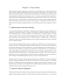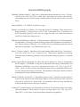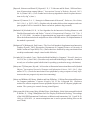
1
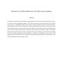
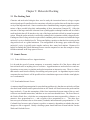
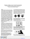
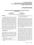
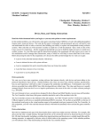
Interactive Collision Detection for Molecular Graphics
by
Greg Turk
A Thesis submitted to the faculty of The University of North
Carolina at Chapel Hill in partial fulfillment of the requirements
for the degree of Master of Science in the Department of Computer Science.
Chapel Hill
1989
Approved by
___________________________________
Advisor: Professor Henry Fuchs
___________________________________
Reader: Professor Frederick P. Brooks, Jr.
___________________________________
Reader: Professor J. Nievergelt
Interactive Collision Detection for Molecular Graphics
Abstract
Collision detection between hard-sphere representations of molecules can be performed in interactive times on existing graphics hardware. This thesis presents a system that allows a user to interactively move a small drug molecule near a larger receptor molecule and have the system immediately inform the user when a collision between the two molecules has occurred. The system uses a
3-D grid data structure to speed up the search for collisions. The collision detection and the generation of images of the molecules are performed by the Pixel-Planes 4 graphics engine. Preliminary
trials of the system had users perform a simple geometric task, and the results indicate that stopping
an object’s motion completely as the response to collisions is a hindrance to such tasks. This
suggests that a better behavior for collision response must be found before collision response can
aid in performing similar geometric tasks.
Acknowledgements
I would like to thank my thesis chair Professor Henry Fuchs, who has supplied ideas and encouragement throughout this project. I also thank Professor Frederick Brooks and Professor J. Nievergelt,
the other members of my thesis committee, for the insightful suggestions and the encouragement
that they both gave to this project.
Ming Ouh-young spent a good deal of time teaching me about many of the issues involved with
molecular docking. I am grateful for the time he has spent with me and for the many good suggestions that he gave me.
Brice Tebbs gave me a good deal of help in dealing with the intricacies of PPHIGS. He also took
the time to talk with me about many of the issues involved with collision detection and put up with
the annoyance of a friend and office mate who had taken on too many projects at once. For these
things I thank him.
I would like to thank all the members of the Pixel-Planes team for the help that they have given me
and for the excellent combination of software and hardware that they have created that is the PixelPlanes system.
Thanks to all the “graphics lab regulars” who have made the g-lab such an enjoyable place to work
through their friendship, enthusiasm and good music. Many of these people agreed to be part of the
user study. David Banks was kind enough to take the photos for this project.
My mom and dad have given me love and encouragement throughout my education. Watching the
enjoyment they found in their work influenced me in my discovery of the joys of learning. For all
of this I give them my love and gratitude.
Last, I would like to thank Anne for the patience and love she has shown me all through the time
that I have worked on this project.
Table of Contents
1 Introduction . . . . . . . . . . . . . . . . . . . . . . . . . . . . . . . . . . . . . 1
2 Molecular Docking . . . . . . . . . . . . . . . . . . . . . . . . . . . . . . . . . 2
2.1 The Docking Task
2.2 Atomic Forces
2.2.1 Trade-offs Between Force Approximations
2.2.2 Non-bonded Atomic Forces
2.2.3 Bond Motion and Internal Vibration
2.3 Previous Docking Systems
3 Collision Detection Algorithms . . . . . . . . . . . . . . . . . . . . . . . . . 5
3.1 Categories of Collision Detection Algorithms
3.2 Grids and Octrees
3.3 BSP-trees and Bounding Volume Hierarchies
3.4 Sweep Algorithms
3.5 Relation Between Collision Detection and Ray Tracing
4 The Bump System . . . . . . . . . . . . . . . . . . . . . . . . . . . . . . . . . 8
4.1 User Interface
4.2 A Hypothetical User Session
4.3 Depth Cues
4.3.1 Rocking
4.3.2 Stereo display
4.3.3 Transparency
4.3.4 Shadows
4.3.5 Other Depth Cues
5 Collision Detection in Bump . . . . . . . . . . . . . . . . . . . . . . . . . . 12
5.1 The Bump System
5.2 Uniform Spatial Subdivision
5.3 Collision Along Path of Motion
5.4 Algorithm Performance
6 A User Study . . . . . . . . . . . . . . . . . . . . . . . . . . . . . . . . . . . 18
6.1 A Simple Task of Geometric Fit
6.2 User Comments
7 Future Work . . . . . . . . . . . . . . . . . . . . . . . . . . . . . . . . . . . . 22
7.1 Enhancements for Molecular Docking
7.2 Interactive Physical Simulation
Chapter 1: Introduction
A researcher using computer graphics to explore the interaction between molecules may wish not
only for a visual representation of the molecules, but also that the behavior of the simulated molecules reflect their physical properties. Highest in importance among the properties of molecules
are the forces that their constituent atoms exert on the atoms of other molecules. The most basic
result of these inter-atomic forces is that two atoms cannot occupy the same location at the same
time. This means that it is necessary to forbid spatial overlap of the two molecules in the world of
molecular interaction. Detecting whether two objects overlap in space is known as interference
checking, and when at least one of the objects is moving this is called collision detection.
This thesis presents a system showing that collision detection between a large receptor molecule
and a small drug molecule can be performed in interactive times on existing graphics hardware.
This system is called bump, and it runs on the Pixel-Planes 4 graphics engine and its host microVax.
Bump displays sphere models of molecules on a raster monitor at interactive rates. A user can move
the position of the drug molecule with a pair of joysticks, and the system forbids motion of the drug
that would cause a collision with the larger molecule.
Chapter 2: Molecular Docking
2.1 The Docking Task
Chemists and molecular biologists have need to study the interaction between a large receptor
molecule and specific small molecules sometimes referred to as probes that can fit into the receptor
cavity of the larger molecule. Some researchers have found that using computer graphics representations of these models helps their understanding of these interactions [Janssen 85]. Often the
structure of the larger molecule is known from crystallographic techniques and the task is to find a
small molecule that will fit into the active site of the larger molecule to block its normal enzymatic
action. When the probe molecule is artificially synthesized it is sometimes called a drug molecule.
Finding an effective drug molecule requires that a candidate probe be maneuvered within the larger
molecule’s cavity to find the best fit. This means finding a position so that the forces acting on the
drug molecule are at a global minimum. The configuration of the energy space within the large
molecule’s cavity is typically quite complex and may have many local minima. Human aid is
helpful in finding this global minimum because current computers are not fast enough to always
find the minimum in the large space of forces.
2.2 Atomic Forces
2.2.1 Trade-offs Between Force Approximations
It is beyond the speed of current computers to accurately simulate all of the forces within and
between molecules in anything close to real-time. Approximations to molecular forces and configurations are necessary to simulate molecular interactions at interactive rates. There is a choice
that must be made between fidelity of modelling and system speed. As algorithms improve and as
computers become faster it will be possible to have simulations agree more with the actual physics
as we understand it.
2.2.2 Non-bonded Atomic Forces
A common simplifying assumption for some docking problems it is that the two molecules will not
alter their bond structure and in particular that no new bonds will form between the probe and the
larger molecule. Given this assumption, all the force interactions between atoms of the two molecules are non-bonded interactions, and there are two such non-bonded forces. The first of these is
the Van der Waals force, which has two components between atoms separated by a distance r: an
attractive force proportional to r -12, and a repulsive force proportional to r -6. The other force
between a pair of atoms is due to electrostatic (Coulomb) interaction and is proportional to 1/r. The
Coulomb force between a pair of atoms is repulsive or attractive depending on whether the atoms’
charges are like or opposite. Ideally a docking system should take into account both the Van der
Waals and Coulomb forces.
2.2.3 Bond Motion and Internal Vibration
There are factors in addition to the Van der Waals and Coulomb forces that play a part in the
dynamics of molecular interaction. Within one of these molecules the relative positions of atoms
does not remain fixed during docking. One way in which the atoms’ relative positions can be
altered is that the angle between two bonds that share a common atom can change because of the
forces resulting from the docking maneuver. For the most part, however, the dihedral angles are
nearly rigid. A second change in shape happens more freely, and this is change in the dihedral (or
torsion) angle about a bond. This is the freedom that atoms have to rotate around the axis of a bond.
Taking into account these changes is at the limit of the state-of-the-art in interactive docking simulations [Karfunkel 86]. In addition to these changes, a molecule in solution has some amount of
internal vibrations that are not due to interactions with other molecules. It is well beyond current
computer technology to simulate these vibrations in an interactive system. Currently the only
programs that attempt to take into account such phenomena are quantum level simulations that
require hours or days on a supercomputer to complete a simple simulation. It should be noted that
systems that measure forces in terms of Van der Waals and Coulomb forces and bond angles are
actually using approximate values, taken from theoretical and empirical results, to estimate the
overall forces, and that quantum models are necessary to better take into account the interaction
between all factors involved in molecular interactions.
2.3 Previous Docking Systems
Several researchers have sought to provide chemists with interactive tools to use in studying molecular docking. Palmer built a system that allows a user to interactively move a stick representation of a drug within the receptor cavity of a macromolecule [Palmer 87]. The program allows
interactive motion of the drug, gives a real-time shaded raster image while holding the view fixed,
reports collisions between drug and receptor, and allows arbitrary positioning of a clipping plane.
Collisions are detected using a method developed by Barry [Barry 80]. The method uses a depth
buffer containing spheres from the receptor molecule that have had their radii enhanced by an
“average” atomic radius. This allows collisions to be detected with one frame buffer lookup per
atom in the drug, and with results that differ little from using the exact Van der Waals radius for
each atom.
The first steps towards interactive collision detection using the Pixel-Planes graphics engine [Fuchs
85] were taken by Srinivasan [Srinivasan 86]. Based on an idea by Brooks [Brooks 85], the system
uses the smart frame buffer of Pixel-Planes to help with a sweep algorithm to detect collisions
between collections of spheres. The method examines many slices of the space to determine if
spheres intersect, and when a collision occurs the display highlights the area of overlap with a
specially designated color. The system cannot be programmed to give other forms of collision
response, however, because there is no way on Pixel-Planes 4 to move data from the frame buffer
back to the host. Hardware has been designed and partially built to provide such readback capabil-
ity for Pixel-Planes 4, but it remains untested [Fuchs and Neumann 89].
Ming Ouh-young and co-workers [Ouh-young 88a,88b] are exploring the use of force-feedback to
aid in molecular docking tasks. The display is generated in real-time on a vector display with the
choice of stick models or Connolly surfaces [Connolly 83] and allows the use of stereo glasses. A
user controls the position of the drug molecule with six degrees of freedom by holding the end of a
master arm of a master/slave remote manipulator pair of mechanical arms. The arm is not just an
input device but also provides force output by pushing back on the user’s hand. The system applies
forces to the user’s hand resulting from the simulated interaction between the drug and receptor
molecules. These forces are calculated in O(n) time for a drug with n atoms using a 3-D table of
pre-computed receptor force values [Pattabiraman 85]. This research is not yet complete, but
preliminary results indicate that force-feedback may indeed be useful to chemists who are trying to
understand the interaction between a given drug and receptor. The path towards this current system was paved by earlier work that used the same master arm to allow interaction with a simple
virtual world of blocks [Kirkpatrick 76].
Chapter 3: Collision Detection Algorithms
The most straightforward algorithm for interference checking between two complex objects is to
make comparisons between all pairs of simple parts of the two objects. For example, if each object
is a collection of spheres then we can check each sphere from object A against each sphere from
object B, and we know that objects A and B intersect if and only if one or more of these pairs
intersect. For two objects with M and N parts this algorithm requires O(MN) time to check for
interference. It would be better to find an algorithm whose speed grows more gracefully with
larger problems.
3.1 Categories of Collision Detection Algorithms
Several categories of geometric algorithms have been used to speed up collision detection in three
dimensions. The first category contains those algorithms that partition space into sub-regions and
then compares parts from the different objects only if the two parts lie in the same space partition.
The second type of algorithms are those that partition the objects based on the geometry of each
object and then use these divisions to prune the tree of all possible part comparisons between
objects. Collision detection by spatial sweep is the final category.
3.2 Grids and Octrees
One common space partition method is that of 3-D grids or uniform spatial subdivision, where
space is divided up into cubical cells all of one size [Bentley and Friedman 79]. To detect collisions
the algorithm places each part from each object into the cell or cells in which that part lies. Every
time a part is placed into a cell the part is checked against all the parts from other objects that have
already been placed into the same cell. The method of 3-D grids was used by [Levinthal 66] to
limit the number of inter-atom comparisons necessary to find minimum energy configurations of
large molecules. The need to know bounds on the locations of the objects and the need to allocate
memory for cells that cover these bounds can be removed by using a hashing scheme based on 3space coordinates [Bentley and Friedman 79].
The octree approach to collision detection is a method halfway between space partitioning and
object partitioning. Here again space is divided up into cubes, but in this case the sizes of the cubes
vary based on how many object parts are in a given region of space. Sparsely populated regions are
covered by large cubes, and regions of space that contain many object parts are divided up into
smaller cubes that cover the region. The name octree refers to the data structure that holds all the
cubes: a tree where each node is either a cube or contains pointers to eight other nodes that each
have information about one-eighth of the parent cube’s region. Octrees have been used to detect
intersections between polygonal objects in systems based on constructive solid geometry [Carlbom
87]. To compute the intersection between two polyhedra each polygon from object A must be split
by every polygon of object B that the polygon from A intersects. With the octree approach, boolean
combinations of polyhedra can be computed without having to make all pairwise comparisons
between polygons from objects A and B.
3.3 BSP-trees and Bounding Volume Hierarchies
An object partitioning algorithm called the binary space partition tree (BSP-tree) has also been
used to speed up intersection calculations for constructive solid geometry [Bloomberg 86] [Thibault
and Naylor 87]. This approach uses a tree with separating planes at each internal node that partition
an object so that groups of parts that are close to each other in space are also collected together
within the tree. If the separating planes are only allowed to be aligned with the natural coordinate
planes then a BSP tree becomes very much like an octree.
Another object partition algorithm is the method of hierarchical bounding volumes. Here the idea
is to use a collection of one kind of simple geometric primitive, such as a cube or a sphere, to bound
groups of parts of an object that are near each other in space. These bounding volumes are arranged
in a tree in which each internal node is a bounding volume that encompasses all object that are its
descendants in the tree. The leaves of the tree contain those parts of an object that are all within the
bounding volume of the parent node. Bounding hierarchies made of cubes have been used by [Segal
and Sequin 88] to limit the number of pairwise polygon intersection tests needed for constructive
solid geometry. Hierarchical bounding areas have been given the name “strip trees” when the
domain is two dimensional and the bounding areas are rectangles [Ballard 81]. Strip trees have
been used to compute intersections between geographical objects such as roads and rivers that are
stored in an on-line map.
3.4 Sweep Algorithms
A sweep algorithm for finding object intersections in N dimensions proceeds by sweeping an N-1
dimensional subspace through the space and makes comparisons between objects each time the
subspace passes over a new object. As a two-dimensional example, consider the problem of finding intersections between pairs of line segments that lie in a plane. To solve this a line is swept
through the plane and a sorted list is maintained of those segments that intersect this line. Each
time the line passes over an end-point of a segment, checks can be made against other segments in
the sorted list to determine whether this segment intersects another [Shamos and Hoey 76]. This
algorithm will find all intersections in O(log n + k) where n is the number of segments and k is the
total number of intersections. The success of a sweep method depends on sorting objects along one
axis, thereby reducing the problem to one fewer dimension, and also depends on the efficiency of
the data structure that keeps track of what objects are currently intersected with the sweeping subspace.
A sweep algorithm for three dimensions has been given by [Hopcroft, Schwartz and Sharir 83] that
determines in O(n log2 n) time whether there exists a pair of spheres that intersect in a collection of
n spheres. The algorithm does not report all such intersections, but will report at least one intersec-
tion if any exist. This algorithm does not appear to be adaptable to seeing whether spheres from
one set intersect with spheres from another set. The algorithm proposed by Brooks [Brooks 85]
[Srinivasan 86] for collision detection on Pixel-Planes is a sweep algorithm, although it differs
from most in that the sweep plane is moved through space in fixed distance jumps. This kind of
sweep algorithm might be called a discrete sweep algorithm and exact solution methods may be
called analytic sweep algorithms. I have not found any analytic space sweep algorithms that have
been used to determine whether two complex objects intersect.
3.5 Relation between collision detection and ray tracing
Several of the techniques described above have been used successfully to speed up the ray tracing
rendering technique. This should not be surprising since ray tracing is an intersection check: the
basic computation is a test to see if a ray intersects any one of a collection of objects in a scene. 3D grids were used for ray tracing by [Fujimoto and Iwata 85], in which they describe a method for
following a ray’s path through the cells of the grid. A method of following a ray’s path through an
octree was given by [Glassner 84]. Rays were checked against bounding volumes by [Weghorst,
Hooper and Greenberg 84], and they give a method for determining which of a set of primitives
should be used to bound a complex object. A method for automatically constructing a hierarchy of
bounding volumes was given by [Goldsmith and Salmon 87], and they also propose a “goodness”
measure for a given bounding hierarchy.
Chapter 4: The Bump System
The focus of this thesis is on a system called bump that performs real-time collision detection of
molecular models on the Pixel-Planes 4 graphics engine. Bump is a working program that provides
an existence proof that collision detection between non-trivial models can be done in interactive
times on existing hardware. It is my hope that other authors of interactive graphics applications
will recognize that graphics workstations now have the power to perform collision detection onthe-fly and that they will consider adding collision detection to their system when this would aid
their application.
4.1 User Interface
Bump was written expressly for interactive docking of hard-sphere representations of molecular
models. Bump allows a user to view molecular models on a monitor and to move one molecule
relative to another molecule using joysticks. Spheres are used to represent the atoms in a molecule.
When collision detection is enabled, bump prevents any motion of a molecule that would cause it to
interpenetrate another molecule. When a collision has occurred, bump indicates this by changing
the colors of the spheres participating in the collision, and in addition bump may be instructed beep
or cause the background to flash. The intent of the collision cues is to provide the user with a better
feel for the interaction between a pair of molecules by giving the molecular models a simplified
physical behavior, that of Van der Waals repulsion between atoms.
In its full-blown configuration, bump allows the user to manipulate both the viewing position and
a single molecule’s position and orientation by using a pair of joysticks boxes, each box consisting
of two three-axis joysticks. Images of the molecules are displayed on the Pixel-Planes monitor as
the user moves the joysticks. One joystick box is used to vary the viewing position by having one
joystick for translation and the other for rotation of the collection of all models that are on the
screen. The other joystick box is used to translate and rotate one particular molecular model. The
user may change which molecule is being moved by a keyboard toggle. If only one joystick box is
available then the user may toggle between changing the view and moving a model by pressing the
space-bar on the keyboard.
4.2 A Hypothetical User Session
Let me describe a hypothetical session with bump. A user specifies that two molecules are to be
displayed and manipulated by bump. One of these is a large receptor molecule and the other is a
smaller drug molecule. Figure 1 shows such a pair of molecules, with dihydrofolate reductase for
the receptor molecule and trimethoprim as the smaller drug molecule. First, the user moves the
viewing position by rotating all objects in the scene so that the receptor site of the larger molecule
is visible, and then uses the view translation joystick so that the site is filling most of the screen. By
a keystroke the user specifies that one joystick box will control the position of the drug molecule,
and then proceeds to move the drug molecule away from the receptor molecule and in front of the
receptor site. Now with a keystroke collision detection is turned on. The user maneuvers the drug
molecule towards the receptor site of the larger molecule and attempts to find a fit into the site. If
the user moves the drug molecule so that it hits the large molecule, the spheres that collide change
color and a beep is heard. Using the graphics display and the collision detection as guides, the user
gets a “feel” for the shapes of the receptor site and drug molecule, and is able to position the drug
molecule where it is meant to rest on the receptor.
Figure 1: Dihydrofolate Reductase and Trimethoprim on Pixel-Planes Monitor
4.3 Depth Cues
Docking a molecule is a task that requires understanding of the spatial relationship between two
molecules. The importance of depth cues to spatial understanding becomes apparent when a user
tries to dock a drug molecule using bump. The only depth cue that is always present in bump is the
cue given by surface obscuration, that is, that the hidden surface display algorithm for spheres on
Pixel-Planes hides the surface of spheres that are behind other spheres. When bump uses hidden
surface obscuration alone it is difficult to understand the relative depths between atoms within the
molecules. Using a joystick to move the view position can give a very strong understanding of
depth relationships, but when the motion is stopped the image becomes flat. Obscuration can be a
powerful depth cue when coupled with additional cues, but alone it is insufficient to give a good
feeling for depth. In addition to surface obscuration, bump provides rocking of the models and
stereo display to enhance depth perception. Both of these depth cues have advantages and drawbacks when used in bump.
4.3.1 Rocking
A user can turn on the automatic rocking of the molecules and can also adjust the magnitude of the
rocking by keyboard commands. When rocking is turned on the molecules gently rock back and
forth about the vertical axis. The rocking is continuous, except that all rocking stops when the user
is moving the joysticks. If rocking were to continue when a molecule is moved a user would have
to synchronize his or her hand motions with that of the rocking to perform fine positioning of a
molecule. This is far too difficult when the axes are decoupled as they are with the joystick controls. Even when the rocking is stopped during joystick motion a user can find that the view
position that the rocking has caused can be less than ideal.
4.3.2 Stereo Display
The second optional depth cue is stereo display, where bump generates two views of the molecules
and a shuttered screen and glasses are used to have one of these images presented to each eye. For
people who can perceive stereo this can be a powerful depth cue. There are a few drawbacks to
using stereo, however. First, the update rate of the display is halved because Pixel-Planes must
create a separate image for the left and right eyes. This means that the motion of the molecules is
not as smooth, and this can be quite an annoyance. In addition, wearing stereo glasses cuts down
on the brightness of the display and the shuttering action can cause fatigue and sometimes headaches for a user.
4.3.3 Transparency
Using partially transparent surfaces is another technique sometimes used to give additional spatial
information. When portions of an object are translucent, detail can be seen of the object that would
normally be obscured by the partially transparent surface. Transparency can make more surfaces
visible at one time, but having too many transparent surfaces may lead to a cluttered and confused
image. In molecular graphics, one form of transparency that has enjoyed much success is the
Connolly surface [Connolly 83]. A Connolly surface is where portions of a surface are displayed as
points that are fairly evenly distributed over the active surface of a molecule. Since the points of a
far surface can be seen between the points of a closer surface this gives the effect of transparency.
Usually a vector display is used to draw such representations. Just now raster graphics hardware is
becoming available that can display transparent surfaces in real-time. It remains to be seen whether
this capability will be useful for molecular graphics.
4.3.4 Shadows
Shadows can provide information about spatial relationships between objects. When one object’s
shadow drapes over a second object we know the relative position of the two objects with respect
to the light source. The depth information given here is indirect, but it is a depth cue none the less.
Kirkpatrick found that the drop shadow of a virtual manipulator was a powerful cue for the task of
positioning the manipulator around a block [Kirkpatrick 76]. While the use of shadows has not yet
been proven helpful for molecular graphics, it is another technique worth exploring.
4.3.5 Other Depth Cues
There are additional depth cues that have been found to be effective for some interactive graphics
applications, and some of these techniques may be incorporated in future versions of bump. Some
of the possibilities include intensity depth cueing, head-motion parallax and a head-mounted display. Intensity depth cueing is where the brightness of an object is diminished based on the distance of the object from the observer. I expect that intensity depth cueing will give a user a rough
notion of depth but that it will not let a user distinguish the relative depth of two atoms that are near
one another. Head-motion parallax is where the motion of the head is tracked and where the view
of the image is calculated based on the head position. This has been found to be a very powerful
depth cue. A head-mounted display is where the user wears a pair of displays, one in front of each
eye, and where the images presented to each eye is based on the tracked head position. A headmounted display can enjoy the benefits of stereo display and head-motion parallax, and thus holds
promise for excellent depth perception.
Chapter 5: Collision Detection in Bump
5.1 The Bump System
Bump was was built by enhancing an existing program called pphront (“pee-front”), which is a
model viewing program for Pixel-Planes that was written by several members of the Pixel-Planes
team. Pphront gets its odd name from being a front-end to Pixel-Planes and because it is written
using a graphics library called PPHIGS [Ellsworth 88]. Differences between bump and pphront
are described in the user’s manual for bump at the end of this thesis.
The Pixel-Planes graphics system is composed of a host processor, a graphics processor, an SIMD
array of processor-enhanced memories and a video display unit [Fuchs 85]. The code for the
PPHIGS graphics library is distributed between the host processor, which is a microVax, and the
graphics processor, which is a Weitek chip set with fast floating point capabilities. The code for
bump proper resides only on the host, but PPHIGS has been enhanced to include collision detection
for this project, and most of this code runs on the graphics processor.
Two new routines were added to PPHIGS, one for static interference checking called
pg_collision_check() and second routine called pg_move_to_touch() that determines collisions
between a moving object and a fixed object. The pg_collision_check() routine accepts two parameters, the names of two graphics structures, and returns a boolean value saying whether the objects
intersect. Unfortunately, static interference detection was found unsuitable for molecular docking
for reasons that will be discussed below. The collision detection routine pg_move_to_touch() was
then written to remedy the problem with static checking. The collision detection routine accepts
the name of two graphics structures and information about how one object is to move, and this
routine returns whether a collision occurred and where the moving object should be stopped so that
it just touches the fixed object.
5.2 Uniform Spatial Subdivision
A number of algorithms for collision detection have been described in the literature. This section
describes the method that bump uses to check for collisions between collections of spheres that
represent molecules. Chapter 6 presents a taxonomy of collision detection algorithms.
The method bump uses to perform collision detection is uniform spatial subdivision. For each
collection of spheres that represents a molecule, the modeling space of the molecule is divided into
a three dimensional grid of cells. Each of the cells in the grid is a cube with side lengths equal to
the diameter of the largest sphere in the model. Every cell has a list of spheres that fall within the
volume of the cell. In order to test whether a sphere S from another model intersects with this
model, it suffices to find if S intersects any spheres in the cells that S falls within. To check whether
molecular models A and B intersect, each of the spheres from model B is checked in this way
against the spheres in model A.
5
Grid for
Receptor
Molecule
Cell contains pointers
to spheres 4, 5 and 6.
4
2
6
1
3
Sphere from drug is
tested against spheres
in four cells of receptor.
Figure 2: Two-dimensional Illustration of Uniform Subdivision
Two variations of uniform subdivision were implemented for bump. One method was to find the
smallest bounding box that encloses a given molecule, and then to create a full 3-D grid of cells that
extends over this range. This requires two passes through the data: one pass to find the bounding
box and a second pass to place the spheres in the appropriate cells. A variation of this was also
implemented, and this was to create a linear array of cells and to use a hash function to translate a
3-space location to an index in this array. The disadvantage of this method is that the hash function
may cause any given cell to contain spheres from widely separated parts of the model, so that the
average number of spheres per cell is likely to be higher than when using a full grid. The advantages of the method are that only one pass is required to place the spheres into cells and no boundary checks are necessary when testing a sphere from the drug against the receptor’s collection of
cells. I found the hash variant to be shorter and easier to debug than the full-grid method.
Molecule
number of atoms
cytochrome
3204
dihydrofolate reductase #1 1294
dihydrofolate reductase #2 2544
DNA
322
hexokinase
3298
superoxide dismutase
4380
transfer RNA
1613
trypsin
2083
average atoms per cell
(hashed, 4096 cells)
14.38
10.31
10.86
8.24
15.34
11.98
9.37
11.60
average atoms per cell
(full grid of cells)
11.01
9.73
10.14
8.76
11.23
10.44
9.56
10.82
Table 1: Average atom density for the two forms of uniform spatial subdivision
Uniform subdivision is particularly well suited to molecular models. The Van der Waals radii do
not differ substantially between the atoms found in organic molecules: the radius of carbon is 1.74
angstroms, oxygen is 1.4 angstroms, nitrogen is 1.54 angstroms and sulfur is 1.8 angstroms. Also,
the forces between atoms in a molecule put an upper bound on the density of atoms in a molecule.
These two facts mean that there is a small upper bound on the number of atoms can that fall within
any one cell of the uniform subdivision for a model. Thus the time complexity of the uniform
spatial subdivision technique for collision detection is O(n), where n is the number of atoms in the
smaller of the two molecules, which in our application is the drug molecule. The right-hand column of Table 1 shows that over a variety of molecules the average number of atoms per cell remains fairly constant at about 10 atoms per cell. The table also shows that there are not too many
more spheres per cell when using a hash table of 4096 entries instead of a full grid of cells.
5.3 Collision Along Path of Motion
When collision detection is turned on in bump, the program forbids any motion of the drug molecule that will cause it to interpenetrate the receptor molecule. Originally what the program did at
a detailed level was to read the positions of the joysticks, compute a new position for the drug
molecule based on this and test to see if this new position would cause interpenetration. If no
collision occurred then the drug was moved to this new position, but if a collision was detected
then the program would signal this to the user and keep the drug molecule at its previous position.
In this way the program guaranteed that the drug molecule would never intersect the larger molecule. For slow movement this was found to be satisfactory, but when the drug molecule was being
moved rapidly this method would cause the drug to stop moving a good distance away from the
point of collision. When a user eased up on the joystick the drug molecule would then take several
small jumps towards the collision point before coming to rest because the joysticks would give a
sequence of progressively smaller motion increments. The problem was that when the drug was
being moved rapidly the distance between consecutive positions of the drug was easily visible to
the user, and a collision could cause the drug to stop far from the receptor molecule. This was my
first encounter with the perils of static interference checking.
Macromolecule
Motion of Drug
position 0
position 1
desired position 2
proposed position
drug touches
macromolecule
drug intersects
macromolecule
Figure 3: The Problem with Static Bump Checking
To remedy the problem with static interference checking, bump now uses a binary search along the
path of the drug’s trajectory to find the position where the collision occurs. Instead of multiple
invocations of the full-blown interference checking method described above, information from the
check that found the collision is used to make this search more rapid. Specifically, when a collision
is found using spatial subdivision, each pair of spheres that participate in the collision are recorded
in a list. This short list of sphere pairs is checked for each proposed position along the path of the
drug, and the new position of the drug is taken to be the position farthest along the path that did not
cause an intersection between pairs of spheres in the list. Although this use of trajectory coherence
is not guarantee to give a correct answer for extremely rapid motion, it has proved to be a suitable
method for the given problem domain.
5.4 Algorithm Performance
The bump program keeps track of how many times collision detection is invoked in a run and uses
the system function gettimeofday() to time each invocation. These values are printed when the
program is exited. To time the collision detection algorithm, a recording of a bump session was
saved in a file. During the session a model of trimethoprim was moved into a cavity of dihydrofolate
reductase while collision detection was turned on. This recording was played back several times
on an unloaded system to get an average time for invocations of the two variants of the collision
detection routine. The average time for a call to collision detection was 0.057 seconds for both the
hash table and full grid methods. Together with the times gathered by hand (below) this means that
roughly 73% of the time is spent displaying the models and 27% is spent checking for collisions.
Method
seconds per frame
no collision detection
0.155
collision detection, hashed cells
0.193
collision detection, full-grid of cells
0.189
Table 2: Timing Statistics for Collision Detection
Performance of the collision detection algorithm was also measured by timing the frame update
rate while displaying models of dihydrofolate reductase and trimethoprim. This timing was done
on an unloaded system using a stopwatch and displaying 100 frames while rotating the model for
trimethoprim continuously. Table 2 shows the times for both collision detection variants and the
time without collision detection. The table shows that bump displays about 5 frames per second
with collision detection turned on and roughly 6.5 frames per second without collisions. The times
indicate that there is little difference between using a hash table and using a full grid of cells. With
collision detection turned on bump spent roughly 80% of its time generating images and 20%
checking for collisions during these timings. Since the model for trimethoprim was somewhat
removed from the dihydrofolate reductase, fewer cells in its neighborhood were filled than if the
models were being bumped against one another. This is probably the reason for the slightly faster
times for calls to the collision detection routines than the times clocked by gettimeofday().
Chapter 6: A User Study
6.1 A Simple Task of Geometric Fit
A small pilot study was performed aimed at evoking comments from the users about the usefulness
of collision detection and response in a geometric fit task. For this first study I judged the system
not yet ready for a full-blown docking task. Instead, users were asked to fit two abstract models
together in a particular configuration. Figure 4 shows a photo of the two objects, a green triple ring
and a red E-shape, in their “docked” configuration.
Figure 4: Two objects in final position of geometric task
Each user was asked to perform the same positioning task twice, once with no collision detection
and once with collision detection turned on. The initial positions of the two objects had them
separated from each other and were the same for both trials. During the trial without collision
detection the user was asked to say when they thought that the objects were docked and not touching, and at that point collision detection was turned on. If the objects were touching, collision
detection was turned off again and the user was asked to make adjustments. This was repeated
until a valid position was reached. Both tasks were performed with the user wearing shuttered
glasses for stereo and both joystick boxes were available for object motion and change of view.
Figure 5: User with Glasses and Stereo Display
The emphasis of this study was on the impressions of the users, so the speed of task performance
was not stressed to the users. Even so, times for each task were recorded. Table 3 lists the ranking
of ease or difficulty of the tasks by the users, and also gives the times required to perform the tasks.
The users were asked to place a mark on a horizontal scale to rate the difficulty of the two tasks, and
this is the origin of the difficulty ratings in the table. Note that almost all users required more time
to perform the task when collision detection was turned on. Reasons for the failure of collision
detection to aid in performing the positioning task are discussed below.
User number
1
2
3
4
5
6
7
Times (minutes:seconds)
Difficulty (0 = easy, 1 = difficult)
no detection
collisions on
no detection
collisions on
3:30
3:34
.42
.30
4:38
6:53
.32
.80
4:49
8:45
.26
.82
3:58
10:17
.53
.78
1:54
2:29
.38
.42
2:21
2:44
.23
.50
3:48
1:44
.58
.33
Table 3: Task difficulty with and without collision detection
Difficult
Users first tried with
collision detection
Users first tried without
collision detection
With
Collision
Detection
Easy
Difficult
Easy
No Collision Detection
Figure 6: Graph of User Rated Difficulty of Tasks
10
Users first tried with
collision detection
With
Collision
Detection
Users first tried without
collision detection
5
0
0
5
10
No Collision Detection
Figure 7: Graph of Times for User Tasks (time in minute)
6.2 User Comments
In addition to ranking the difficulty of the two tasks, the users were asked for written comments and
suggestions about the system. The most common suggestion was to have a mode where interpenetration is detected and indicated by changing the sphere colors but where all objects are allowed to
move freely. The users found that the visual cue for collisions was helpful but said that the response to collisions was a hindrance. Sometimes when collision detection was turned on they
knew where they wanted to go but the system would not allow the motion. The failure of collision
response to aid in the tasks is serious, and this issue is discussed in the chapter on future work.
Another commonly voiced objection was to the way the joysticks controlled the motion of the
objects. Some users found the assignment of rotation axes to the joysticks to be counter-intuitive
and suggested swapping the joystick controls for the y and z axes. In the current configuration,
rotation about the x (horizontal) axis is controlled by moving a joystick left or right, rotation about
y (vertical) is achieved by moving a joystick forward or back and rotation about z (depth) is a result
of twisting the joystick. Translation in x, y and z matches the x, y and z movements for rotation
using joysticks. Users suggested that it would be more natural to twist a joystick to rotate an object
about the y (vertical) axis, and to move a joystick forward and back to perform rotation about the z
(depth) axis.
Another suggestion was to have the joysticks control motion in object space rather than in screen
space. These users said they found it annoying that a change of viewpoint also changed the mapping between joysticks and object motion. I have tried object space positioning using joysticks and
found it to be non-intuitive, but a user study would be a better way to determine whether others find
this to be more natural.
Chapter 7: Future Work
Most interactive graphics applications to date have restricted themselves to the rapid display of
objects and have paid scant attention to the physical properties of the objects as they interact. With
the new generation of graphics workstations, researchers will now find the power to simulate more
physical properties of the objects in interactive times. The bump system described in this thesis is
a small step towards adding physical properties to graphical models. There are two clear extensions to this work. One direction is to further explore the needs of chemists and biologists for
molecular docking, since the bump system is still a crude tool. Another path to future work is to
add to the array of physical properties that can be simulated interactively on a graphics workstation.
7.1 Enhancements to Molecular Docking
It is clear from the small user study that the collision response of bump needs to be re-thought. One
possibility, suggested by the users, is to remove all response to collisions, and only have visual cues
from collision detection. Another possibility is to try other forms of collision response. One that
comes to mind is to have an object’s motion stopped only in the direction of the collision and to
allow the object to slide along the surface of the object that it is colliding with. I feel that it is
important to explore these and other alternatives to the collision response given in bump, and I plan
to do so in the near future.
For the task of molecular docking, bump is probably most deficient in its model of the forces
between molecules. Modeling the interaction between molecules as if atoms were hard spheres is
just an approximation to the Van der Waals force. This model totally ignores electrostatic forces. A
logical next step would be to incorporate the hard-sphere collision detection in a system that already models both Van der Waals and Coulomb forces by the technique of [Pattabiraman 85]. The
method described by Pattabiraman is a fast technique that uses a table to store forces of atoms at
positions on a grid. Using hard-sphere collision detection would help overcome the problem in
their technique of undersampling the strong force given by Van der Waals forces.
Another restriction in bump is that all bonds of the molecules remain fixed. The torsion angles of
bonds in a drug can rotate quite freely when the molecule is moved into a receptor site. It would be
possible to extend bump to allow changing of these angles as the molecule is being docked. Indeed, the entire conformation of the drug molecule could be altered as rapidly as necessary and the
collision detection routine would perform just as well.
7.2 Interactive Physical Simulation
The domain of molecular models is just one domain where interactive physical simulation may be
helpful in understanding a problem. The hard-sphere models that bump uses are a very restricted
class of models. The range of models that the collision detection routines understand should be
expanded. In particular, many graphics applications choose polygons as the building blocks to
make polyhedral models, and several techniques have been described in the literature for determining collisions between polyhedra [Boyse 79] [Maruyama 72] [Dobkin and Kirkpatrick 82]. The
collision detection routine in bump could be extended to handle polygons. Polygons can be placed
in 3-D cells as easily as spheres, and with the addition of a polygon-polygon intersection routine
bump could then understand collisions between polyhedral models. This addition is straightforward, and I plan in the near future to extend the current PPHIGS collision detection routine to
recognize collisions between polyhedral models. This should open the way toward more realworld fidelity for other applications that use the PPHIGS graphics library.
The method of 3-D grids is only suitable for collision detection among objects that are composed
of many elements that are evenly distributed in space and roughly uniform in size. Other techniques will prove to be faster for detecting collisions when there is a wide range in level of detail
within the objects. I expect that most of the collision detection techniques outlined in earlier will
be useful for interactive collision detection under certain conditions. I am especially enthusiastic
about the automatic building of bounding hierarchies for the purposes of collision detection.
Collision detection is just one step towards bringing more physical fidelity to interactive computer
graphics. Future graphics systems should incorporate many more physical properties into the behavior of virtual objects. Bump completely deadens the motion of an object that participates in a
collision. When two real-world objects collide, however, there is an exchange of both linear and
angular momentum, and the object’s material properties such as elasticity and friction plays a large
part in the resulting behavior. Recent work in computer graphics has been taking the first steps
towards simulating the interaction between rigid objects [Hahn 88] [Moore and Wilhelms 88].
These techniques should be moved into the realm of interactive computer graphics.
Appendix: Bump User’s Manual
A.1 Starting and Exiting the Program
Bump must be executed on the Pixel-Planes 4 microVax host, currently called pxpl4. Text information from the program will be displayed in the window from which the program was invoked and
the graphical images of molecules will be displayed on the Pixel-Planes 4 monitor. The executable
file bump can be found in the directory ~turk/pphront. Bump is invoked with command parameters
that are the names of pphigs archive files that contain the geometry for molecules. Here is a sample
invocation of bump:
bump trm dhfr
The above line specifies that the molecules contained in the two archive files trm.archive and
dhfr.archive are to be displayed by bump. The PPHIGS archive description of each molecule must
be a collection of spheres. Once the program has been invoked, the molecules will be displayed on
the Pixel-Planes 4 monitor and can be moved around by using the joysticks. To exit the program,
type the letter “q” at the keyboard. If bump is terminated abnormally by typing control-C you
should execute the “reset” command to have commands echo normally on the screen.
A.2 Program Basics
When bump is first run the text screen should look like figure 8. The mode “View” at the top of the
screen indicates that the joysticks control the location from which the molecules are being viewed.
This means that joystick motions will cause all objects in the scene to move as a unit. The left
joystick controls translation of the molecules and the right joystick rotates them. To select just one
object to be moved, press the space bar once. This should cause the mode indicated on the screen
to be “Object”, and now the two joysticks control the position and orientation of just one of the
molecules. The name of the object currently being manipulated is indicated at the top of the screen.
To change which object you can move, press “j” until the name of the correct object is indicated.
Using the space bar, the return key and the joysticks you should be able to view the molecules from
any angle and position them in any arbitrary configuration.
Figure 8: Text Screen of Bump Session
By default, collision detection is turned off, so the molecules are allowed to pass through one
another. To switch collision detection on, first make sure that the molecules are separated from one
another and then type “c”. Now motion of one molecule through another molecule is forbidden.
When two molecules collide the colors of the spheres that touched change color. If collision detection is turned on when two molecules are interpenetrating then neither molecule will be allowed to
move with respect to the other. If this happens, turn collisions off by typing “c”, move the molecules apart and then turn collisions on again.
A.3 Stereo Bump
By default, bump displays just one view of the molecules. Stereo images can be generated by
typing “S”. This will cause two images, one for each eye, to be displayed on the screen simultaneously. The image for the left eye is displayed on even-numbered scan lines and the right eye
image is displayed on odd-numbered scan lines. The inter-ocular distance can be made larger or
smaller by typing “[” and “]”. To view such an image, the user should place a polarizing plate in
front of the monitor and wear circularly polarized glasses that are made to view objects through
this plate. This arrangement lets light through the glasses to the left eye during the first (evennumbered) scan of the image, and then let light through to the right eye during the odd-numbered
scan. The polarizing plate used at UNC requires that the display driving the plate to have a scan
rate of 30 hertz. To set Pixel-Planes for display on a 30 hertz monitor, set the environment variable
PXSCAN to 30 before executing bump. Setting up the stereo plate is not straightforward, and the
easiest thing to do is have an experienced user show you the necessary steps.
A.4 Differences Between Bump and Pphront
The bump program is an extension of the pphront program. A user of pphront should be aware of
the differences between the two programs. By default, bump assumes both the use of joysticks and
sphere mode, so the “-j” and “-s” options of pphront are not necessary. All of the keyboard commands that pphront uses to move objects have been removed from bump. The space bar toggles
between Fruit and Object mode. Fly mode has been omitted and Light mode is specified by the “l”
key. This change was made because switching between View and Object mode is a very common
event when docking a molecule. Finally, the user need not hold down the shift key when typing “q”
to exit the program.
A.5 Command Line Options
The bump program can be invoked with several command line options that control its behavior.
Among these options are the use of two joystick boxes, the recording or playback of a user’s
session and the selection of collision detection algorithm. Here is a list of command line options:
-J
Specifies that two joystick boxes are to be used. One box controls the view and the
second box controls motion of a single molecule.
-b
Has bump use the brute-force collision detection algorithm. This is used for timing
comparisons, and is not of much interest to most users.
-l logfile
Records a user’s actions in a file for later playback. Both joystick motion and
keystrokes are recorded in the file “logfile”.
-p logfile
Plays back a file that was recorded using the “-l” option. All control of the program
is from the file and a user’s keystrokes and joystick motions are ignored. When the
playback is finished, the program execution is ended.
A.6 Keyboard Toggles
Below is a list of keystrokes that change settings of various parameters of bump. Most of these are
indicated on the text screen when bump is being run (see figure 8).
space
Toggles between View and Object mode.
l
Changes joysticks to and from Light mode.
j
Changes which object’s motion is controlled by the joysticks.
c
Turns on and off collision detection.
t
Turns on/off screen door transparency and select the object to be transparent.
f
Toggles whether the background flashes when a collision occurs.
b
Toggles whether a beep is made when a collision occurs.
v
Executes a video load. Use this when the program begins with a bad video load.
)
Turn on or increase amount of rocking.
(
Decrease or turn off rocking.
.
Increase the radii of the spheres in the models.
,
Decrease the radii of spheres.
S
Turn stereo on/off.
[
Decrease inter-ocular distance for stereo.
]
Increase inter-ocular distance for stereo.
q or Q
Quit the program.
Annotated Bibliography
[Ballard 81] Ballard, Dana H., “Strip Trees: A Hierarchical Representation for Curves,” Communications of the ACM, Vol. 24, No. 5, (May 1981). (Rectangles are used to create hierarchical bounding areas for efficient queries of planar features in maps such as roads, rivers and
cities.)
[Barry 80] Barry, C. D., MMS-X Newsletter, 2 pages.
[Bentley and Friedman 79] Bentley, Jon Louis and Jerome H. Friedman, “Data Structures for
Range Searching,” Computing Surveys, Vol. 11, No. 4, (December 1979). (Excellent survey
article describing projection, cells, k-d trees, range trees and a few other data structures
useful for n-dimensional range queries.)
[Bloomberg 86] Bloomberg, Sandra H., “A Representation of Solid Objects for Performing Boolean Operations,” University of North Carolina at Chapel Hill, Department of Computer Science Technical Report TR86-006. (Use of BSP-trees for performing regularized boolean
operations on polyhedra. See [Thibault and Naylor 87].)
[Boyse 79] Boyse, John W., “Interference Detection Among Solids and Surfaces,” Communications of the ACM, Vol. 22, No. 1, (January 1979). (A brute-force algorithm for detecting
collisions between stationary polyhedra and a polyhedron undergoing linear or rotational
motion.)
[Brooks et al 83] Brooks, Bernard R., R. E. Bruccoleri, B. D. Olafson, D. J. States, S. Swaminathan
and M. Karplus, “CHARMM: A Program for Macromolecular Energy, Minimization, and
Dynamics Calculations,” Journal of Computational Chemistry, Vol. 4, No. 2, pp. 187-217
(1983). (This is an often referenced program that allows the user many trade-offs between
accuracy and speed for energy calculations. The appendices of this paper contain a wealth of
information about atom and bond parameters.)
[Brooks 85] Brooks, Frederick P., Jr., Pixel-Planes spheres memo. (Describes how the quadratic
terms for scan conversion and z-buffering of spheres can be factored out of the expression
and saved at each pixel of a frame buffer. Also describes a discrete sweep algorithm for
collision detection between collections of spheres.)
[Carlbom 87] Carlbom, Ingrid, “An Algorithm for Geometric Set Operations using Cellular Subdivision Techniques,” IEEE Computer Graphics and Applications, Vol. 7, No. 5, pp. 44-55
(May 1987). (Uses octrees to speed up boolean operations on polyhedra.)
[Connolly 83] Connolly, Michael L., “Solvent-Accessible Surfaces of Proteins and Nucleic Acids,”
Science, Vol. 221, No. 4612, pp. 709-713 (August 1983). (A probe sphere is rolled on the van
der Waals surface of molecule to describe the surface as a set of points for calligraphic display
or as parts of spheres and tori for display on raster devices.)
[Dobkin and Kirkpatrick 82] Dobkin, David P. and David G. Kirkpatrick, “Fast Detection of Polyhedral Intersections,” Automata, Languages and Programming (Ninth Colloquium, Aarhus,
Denmark), Lecture Notes in Computer Science 140, Springer-Verlag, July 1982. (A method
for determining intersection between convex polyhedra in O(log2 n) time.)
[Ellsworth 88] Ellsworth, David, “Pixel-Planes Hierarchical Interactive Graphics System:
Programmer’s Manual,” Department of Computer Science, University of North Carolina at
Chapel Hill, April 1988, 38 pages. (Description of UNC variant of the PPHIGS+ display list
graphics library.)
[Fuchs 85] Fuchs, Henry, Jack Goldfeather, Jeff P. Hultquist, Susan Spach, John Austin, Frederick
P. Brooks, Jr., John Eyles and John Poulton, “Fast Spheres, Shadows, Textures, Transparencies, and Image Enhancements in Pixel-Planes,” Computer Graphics, Vol. 19, No. 3, (Siggraph
85), pp. 111-120. (Gives an overview of Pixel-Planes 4 and describes SIMD versions of
several commonly used techniques for image generation.)
[Fuchs 89] Fuchs, Henry and Ulrich Neumann, personal communication. (A board to read the
video stream from Pixel-Planes 4 has been built but remains untested.)
[Fujimoto and Iwata 85] Fujimoto, Akira and K. Iwata, “Accelerated Ray Tracing,” Proceedings of
Computer Graphics Tokyo ’85 (April 1985). (Uniform spatial subdivision for rapid ray tracing of large data sets.)
[Glassner 84] Glassner, Andrew, “Space Subdivision for Fast Ray Tracing,” IEEE Computer Graphics
and Applications, Vol. 4, No. 10, pp. 15-22 (October 1984). (Octree subdivision to speed up
ray tracing.)
[Goldsmith and Salmon 87] Goldsmith, Jeffrey and J. Salmon, “Automatic Creation of Object
Hierarchies for Ray Tracing,” IEEE Computer Graphics and Applications, Vol. 7, No. 5, p.
14-20 (May 1987). (Presents a method for measuring the goodness of a bounding hierarchy
and says that generating a few random hierarchies and picking the best will give a reasonable
hierarchies.)
[Hahn 88] Hahn, James K., “Realistic Animation of Rigid Bodies,” Computer Graphics, Vol. 22,
No. 4 (Siggraph ’88). (Rapid method of simulating collisions between polyhedral objects,
taking into account friction and elasticity. Also gives method of controlling articulated figures within simulation framework.)
[Hopcroft, Schwartz and Sharir 83] Hopcroft, J. E., J. T. Schwartz and M. Sharir, “Efficient Detection of Intersections among Spheres,” International Journal of Robotics Research, Vol. 2,
No. 4, (Winter 1983). (Gives a rather involved sweep algorithm to check for sphere intersections in O(n log2 n) time.)
[Janssen 85] Janssen, P. A. J., “Strategies in Pharmaceutical Research,” Endeavour, New Series,
Vol. 9, No. 1, p. 28-33 (1985). (Explains why the author believes that computers and computer graphics will be essential for future research in synthetic drug research.)
[Karfunkel 86] Karfunkel, H. R., “A Fast Algorithm for the Interactive Docking Maneuver with
Flexible Macromolecules and Probes,” Journal of Computational Chemistry, Vol. 7, No. 2,
pp. 113-128 (1986). (A number of approximations are proposed to rapidly compute forces
where the both macromolecule and probe are allowed flexible motion. No implementation of
the method is presented.)
[Kirkpatrick 76] Kirkpatrick, Paul Jerome, “The Use of a Kinesthetic Supplement in an Interactive
Graphics System,” Ph.D. Dissertation, Department of Computer Science at University of
North Carolina at Chapel Hill (1976). (Shows that force-feedback by using a mechanical arm
can help to understand a simple virtual world of blocks.)
[Levinthal 66] Leventhal, Cyrus, “Molecular Model-building by Computer,” Scientific American,
Vol. 214, No. 6, (June 1966). (Describes early molecular modelling by computer. Notable as
an early use of uniform spatial subdivision for speeding up molecular energy calculations.)
[Maruyama 72] Maruyama, Kiyoshi, “A Procedure to Determine Intersections Between Polyhedral
Objects,” International Journal of Computer and Information Sciences, Vol. 1, No. 3, (September 1972). (Checks for intersection of two polyhedra by using a sequence of early rejection tests that are progressively more time-consuming.)
[Moore and Wilhelms 88] Moore, Matthew and Jane Wilhelms, “Collision Detection and Response
for Computer Animation,” Computer Graphics, Vol. 22, No. 4 (Siggraph ’88). (Presents a
method for collision response between polyhedral objects for use in computer graphics animation. The system gives control of many-jointed figures.)
[Ouh-young 88a] Ouh-young, Ming, Michael Pique, John Hughes, Neela Srinivasan and Frederick
P. Brooks, Jr., “Using a Manipulator for Force Display in Molecular Docking,” Proceedings
of the 1988 IEEE International Conference on Robotics and Automation, Vol. 3, April 24-29,
1988, pp. 1824-1829. (A remote manipulator arm is used to present docking forces to the
user’s hand.)
[Ouh-young 88b] Ouh-young, Ming, D. V. Beard, F. P. Brooks, “Force Display Performs Better
than Visual Display in a Simple 6-D Docking Task,” to appear. (A user moves a bar attached
to six virtual springs and feels their forces as they are presented to the hand by a manipulator
arm.)
[Palmer 87] Palmer, Thomas Cheek, “Docktool: A Dynamically Interactive Raster Graphics Visualization for the Molecular Docking Problem,” Master’s Thesis, Department of Computer
Science, University of North Carolina at Chapel Hill, TR87-013. (Uses an extended depth
buffer to perform collision detection in O(n) time for drug with n atoms.)