1
OpenSCAD User Manual
OpenSCAD User Manual
The latest reviewed version was approved on 3 June 2013. There are 6 pending
changes awaiting review.
OpenSCAD is a software for creating solid 3D CAD objects. It is free software and available
for GNU/Linux, MS Windows and Apple OS X.
Unlike most free software for creating 3D models (such as the well-known application
Blender), OpenSCAD does not focus on the artistic aspects of 3D modelling, but instead
focuses on the CAD aspects. So it might be the application you are looking for when you are
planning to create 3D models of machine parts, but probably is not what you are looking for
when you are more interested in creating computer-animated movies.
OpenSCAD is not an interactive modeller. Instead it is something like a 3D interpreter that
reads in a script file that describes the object and renders the 3D model from the script
file. This gives you (the designer) full control over the modelling process and enables you
to easily change any step in the modelling process, or even to produce designs that are
defined by configurable parameters.
OpenSCAD provides two main modelling techniques: First, constructive solid geometry (CSG)
and second, extrusion of 2D outlines. Autocad DXF files are used as the data exchange format
for the 2D outlines. In addition to 2D paths for extrusion, it is also possible to read
design parameters from DXF files. In addition to reading DXF files, OpenSCAD can also read
and create 3D models in the STL and OFF file formats.
OpenSCAD can be downloaded from http://openscad.org/. You may find extra information in the
mailing list.
People who don't want to (or can't) install new software on their computer may be able to
use OpenJSCAD ( http://OpenJSCAD.org/ ), a port of OpenSCAD that runs in a web browser.
A pt_BR translation of this document is avaliable on GitHub repository (not completed/on
development) [1]
First Steps
1
Overview
A printable version of OpenSCAD User Manual is available. (edit it)
1.
2.
3.
4.
Introduction
First Steps
The OpenSCAD User Interface
The OpenSCAD Language
1. Primitive Solids - cube, sphere, cylinder & polyhedron
2. General - comments, variables & input, dxf_dim()
3. Mathematical Operators
4. Mathematical Functions
1. Trigonometric (cos sin tan acos asin atan atan2)
2. Other (abs ceil exp floor ln len log lookup max min norm pow rands round
sign sqrt)
5. String Functions - str
6. Transformations - Size & placement. scale, resize, rotate, translate, mirror,
multmatrix, color, minkowski & hull
7. Conditional and Iterator Functions - for, if & assign
8. CSG Modelling - Combine primitives. union, difference, intersection & render
9. Modifier Characters - Debugging aids, % # ! *
10.Modules - Write your own primitive/transformation function
11.Include Statement
12.Other Language Features - Special '$' variables, user-defined functions, echo,
render, surface, search , version() & version_num()
5. Using the 2D Subsystem
1. 2D Primitives - square, circle, polygon & import_dxf
2. 3D to 2D Projection - projection
3. 2D to 3D Extrusion - linear_extrude & rotate_extrude
4. DXF Extrusion
5. Other 2D formats
6. STL Import and Export
1. STL Import
2. STL Export
7. Commented Example Projects
8. Using an external Editor with OpenSCAD
9. Using OpenSCAD in a command line environment
10. Building OpenSCAD from Sources
1. Building on Linux/UNIX
2. Cross-compiling for Windows on Linux or Mac OS X
3. Building on Windows
4. Building on Mac OS X
5. Submitting patches
11. Libraries
12. Command Glossary - Very short name and syntax reference
2
OpenSCAD User Manual/Introduction
< OpenSCAD User Manual
The latest reviewed version was checked on 15 October 2013. There are 4 pending
changes awaiting review.
OpenSCAD is a software for creating solid 3D CAD objects. It is free software and available
for GNU/Linux, MS Windows and Apple OS X.
Unlike most free software for creating 3D models (such as the well-known application
Blender), OpenSCAD does not focus on the artistic aspects of 3D modelling, but instead
focuses on the CAD aspects. So it might be the application you are looking for when you are
planning to create 3D models of machine parts, but probably is not what you are looking for
when you are more interested in creating computer-animated movies.
OpenSCAD is not an interactive modeller. Instead it is something like a 3D interpreter that
reads in a script file that describes the object and renders the 3D model from the script
file. This gives you (the designer) full control over the modelling process and enables you
to easily change any step in the modelling process, or even to produce designs that are
defined by configurable parameters.
OpenSCAD provides two main modelling techniques: First, constructive solid geometry (CSG)
and second, extrusion of 2D outlines. Autocad DXF files are used as the data exchange format
for the 2D outlines. In addition to 2D paths for extrusion, it is also possible to read
design parameters from DXF files. In addition to reading DXF files, OpenSCAD can also read
and create 3D models in the STL and OFF file formats.
OpenSCAD can be downloaded from http://openscad.org/. You may find extra information in the
mailing list.
People who don't want to (or can't) install new software on their computer may be able to
use OpenJSCAD ( http://OpenJSCAD.org/ ), a port of OpenSCAD that runs in a web browser.
A pt_BR translation of this document is avaliable on GitHub repository (not completed/on
development) [1]
First Steps
OpenSCAD User Manual/First Steps/Creating
a simple model
< OpenSCAD User Manual | First Steps
The latest reviewed version was checked on 18 March 2013. There are 4 pending
changes awaiting review.
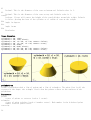
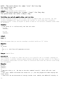
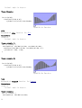
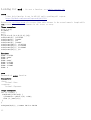
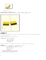
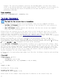
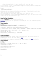
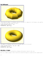
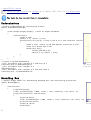
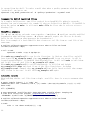
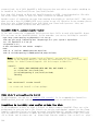
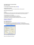
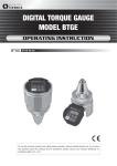
For our first model we will create a simple 2 x 3 x 4 cuboid. In the openSCAD editor, type
the following one line command:
Usage example 1 - simple cuboid:
3
cube([2,3,4]);
OpenSCAD Simple Cuboid
Compiling and rendering our first model
The cuboid can now be compiled and rendered by pressing F6 while the openSCAD editor has
focus.
See also
Positioning an object
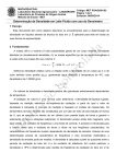
OpenSCAD User Manual/First Steps/Opening
an existing example model
< OpenSCAD User Manual | First Steps
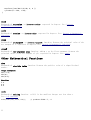
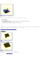
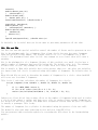
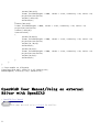
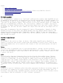
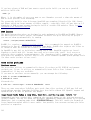
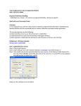
OpenSCAD after starting
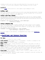
Open one of the many examples that come with OpenSCAD (File, Examples, e.g.
example004.scad). Or you can copy and paste this simple example into the OpenSCAD window:
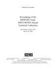
Usage example 1 - example004.scad:
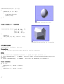
difference() {
cube(30, center=true);
sphere(20);
}
translate([0, 0, 30]) {
cylinder(h=40, r=10);
}
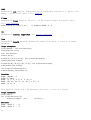
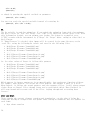
4
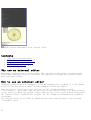
OpenSCAD after pasting the example code and pressing
F5
Then press F5 to get a graphical preview of what you typed.
You get three types of movement in the preview frame:
1. Drag with left mouse button to rotate the view. The bottom line will change the rotate
values.
2. Drag with an other mouse button to translate (move) the view. The bottom line will
change translate values.
3. Use the mouse scroll to zoom in and out. Alternatively you can use the + and - keys,
or right-drag with the mouse while pressing a shift key. The Viewport line at the
bottom of the window will show a change in the distance value.
OpenSCAD User Manual/First
Steps/Positioning an object
< OpenSCAD User Manual | First Steps
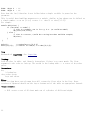
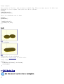
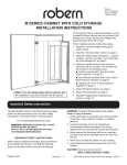
We have already seen how to create a simple cuboid. Our next task is to attempt to use the
translate positioning command to place an identical cuboid next to the existing cuboid:
Usage example 1 - positioning an object:
cube([2,3,4]);
translate([3,0,0]) {
cube([2,3,4]);
}
OpenSCAD positioning an object
There is no semicolon following the translate command
Notice that there
translate command
the effect of the
the same position
5
is no semicolon following the translate command. This is because the
relates to the following object. If the semicolon was not omitted, then
position translation would end, and the second cuboid would be placed at
as the first cuboid.
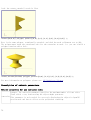
OpenSCAD User Manual/First Steps/Changing
the colour of an object
< OpenSCAD User Manual | First Steps
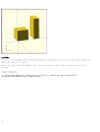
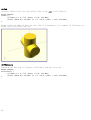
We can change the color of an object by giving it RGB values. Instead of the traditional RGB
values from 0 to 255 floating point values are used from 0.0 to 1.0.
Usage example 1 - changing the color of an
object:
color([1,0,0]) cube([2,3,4]);
translate([3,0,0])
color([0,1,0]) cube([2,3,4]);
translate([6,0,0])
color([0,0,1]) cube([2,3,4]);
OpenSCAD changing the color of an
object
Color names can be used in the 2011.12 version (and newer). The names are the same used for
Web colors. For example: color("red") cube();
If you think of the entire command as a sentence, then color() is an "adjective" that
describes the "object" of the sentence (which is a "noun"). In this case, the object is the
cube() to be created. The adjective is placed before the noun in the sentence, like so:
color() cube();. In the same way, translate() can be thought of as a "verb" that acts
upon the object, and is placed like this: translate() color() cube();. The following
code will produce the same result:
translate([6,0,0])
{
color([0,0,1])
cube([2,3,4]);
}
// notice that there is NO semicolon
// notice the semicolon is at the end of all related commands
Changing the colors only works in Preview mode (F5). Render mode (F6) does not currently
support color.
Category:
• OpenSCAD User Manual
6
OpenSCAD User Manual/First Steps/Model
views
< OpenSCAD User Manual | First Steps
The latest reviewed version was checked on 23 June 2013. There are 2 pending
changes awaiting review.
The text in its current form is incomplete.
The openscad model view window provides a variety of view options.
Contents
•
•
•
•
1
2
3
4
CGAL Surfaces
CGAL Grid Only
The OpenCSG View
The thrown together view
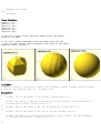
CGAL Surfaces
The surface view is the initial model view that appears when the model code is first
rendered.
CGAL Grid Only
The Grid Only view presents only the "scaffolding" beneath the surface, also known as a
wireframe. Think of the Eiffel Tower.
A wire frame is a visual presentation of a three dimensional or physical object. Using a
wire frame model allows visualization of the underlying design structure of a 3D model.
Since wireframe renderings are relatively simple and fast to calculate, they are often used
in cases where a high screen frame rate is needed (for instance, when working with a
particularly complex 3D model, or in real-time systems that model exterior phenomena). When
greater graphical detail is desired, surface textures can be added automatically after
completion of the initial rendering of the wireframe. This allows the designer to quickly
review changes or rotate the object to new desired views without long delays associated with
more realistic rendering. The wire frame format is also well suited and widely used in
programming tool paths for DNC (Direct Numerical Control) machine tools. Wireframe models
are also used as the input for CAM(computer-aided manufacturing). Wireframe is the most
abstract and least realistic of the three main CAD models. This method of modelling consists
only of lines, points and curves defining the edges of an object. (From Wikipedia:
http://en.wikipedia.org/wiki/Wire-frame_model)
The OpenCSG View
This view mode utilizes the open constructive solid geometry library to generate the model
view utilizing OpenGL. If the OpenCSG library is not available or the video card or drivers
7
do not support OpenGL, then this view will produce no visible output.
The thrown together view
The thrown together view provides all the previous views, in the same screen.
OpenSCAD User Manual/The OpenSCAD User
Interface
< OpenSCAD User Manual
This page may need to be reviewed for quality.
Contents
• 1 View navigation
• 2 View setup
• 2.1 Render modes
• 2.1.1 OpenCSG (F9)
• 2.1.1.1 Implementation Details
• 2.1.2 CGAL (Surfaces and Grid, F10 and F11)
• 2.1.2.1 Implementation Details
• 2.2 View options
• 2.2.1 Show Edges (Ctrl+1)
• 2.2.2 Show Axes (Ctrl+2)
• 2.2.3 Show Crosshairs (Ctrl+3)
• 2.3 Animation
• 2.4 View alignment
View navigation
The viewing area is navigated primarily using the mouse:
• Dragging with the left mouse button rotates the view along the axes of the viewing
area. It preserves the vertical axis' direction.
• Dragging with the left mouse button when the shift key is pressed rotates the view
along the vertical axis and the axis pointing towards the user.
• Dragging with the right mouse button moves the viewing area.
• For zooming, there are four ways:
• using the scroll wheel
8
• dragging with the middle mouse button
• dragging with the right or middle mouse button and the shift key pressed
• the keys + and Rotation can be reset using the shortcut Ctrl+0. Movement can be reset using the shortcut
Ctrl+P.
View setup
The viewing area can be configured to use different rendering methods and other options
using the View menu. Most of the options described here are available using shortcuts as
well.
Render modes
OpenCSG (F9)
This method produces instantaneous results, but has low frame rates when working with highly
nonconvex objects.
Note that selecting the OpenCSG mode using F9 will switch to the last generated OpenCSG
view, but will not re-evaluate the source code. You may want to use the Compile function
(F5, found in the Design menu) to re-evaluate the source code, build the OpenCSG objects and
then switch to OpenCSG view.
Implementation Details
In OpenCSG mode, the OpenCSG library is used for generating the visible model. This library
uses advanced OpenGL features (2.0) like the Z buffer and does not require an explicit
description of the resulting mesh – instead, it tracks how objects are to be combined. For
example, when rendering a spherical dent in a cube, it will first render the cube on the
graphics card and then render the sphere, but instead of using the Z buffer to hide the
parts of the sphere that are covered by the cube, it will render only those parts of the
sphere, visually resulting in a cube with a spherical dent.
CGAL (Surfaces and Grid, F10 and F11)
This method might need some time when first used with a new program, but will then have
higher framerates.
As before with OpenCSG, F10 and F11 only enable CGAL display mode and don't update the
underlying objects; for that, use the Compile and Render function (F6, found in the Design
menu).
To combine the benefits of those two display methods, you can selectively wrap parts of your
program in a render function and force them to be baken into a mesh even with OpenCSG mode
enabled.
Implementation Details
The acronym CGAL refers to The Open Source Computational Geometry Algorithms Library.
In CGAL mode, the CGAL library is used to compute the mesh of the root object, which is then
displayed using simple OpenGL.
9
View options
Show Edges (Ctrl+1)
The difference between the CGAL and OpenSCAD approaches can be seen at edges created by
boolean operations.
If Show Edges is enabled, both OpenCSG and CGAL mode will render edges as well as faces,
CGAL will even show vertices. In CGAL grid mode, this option has no effect.
Enabling this option shows the difference between OpenCSG and CGAL quite clearly: While in
CGAL mode you see an edge drawn everywhere it "belongs", OpenCSG will not show edges
resulting from boolean operations – this is because they were never explicitly calculated
but are just where one object's Z clipping begins or ends.
Show Axes (Ctrl+2)
If Show Axes is enabled, the origin of the global coordinate system will be indicated by an
orthogonal axes indicator. Additionally, a smaller axes indicator with axes names will be
shown in the lower left corner of the viewing area. The smaller axes indicator is marked x,
y, z and coloured red, green, blue respectively.
Show Crosshairs (Ctrl+3)
If Show Crosshairs is enabled, the center of the viewport will be indicated by four lines
pointing in the room diagonal directions of the global coordinate system. This is useful
when aligning the viewing area to a particular point in the model to keep it centered on
screen during rotation.
Animation
The Animate option adds an animation bar to the lower edge of the screen. As soon as FPS and
Steps are set (reasonable values to begin with are 10 and 100, respectively), the current
Time is incremented by 1/Steps, FPS times per second, until it reaches 1, when it wraps back
to 0.
Every time Time is changed, the program is re-evaluated with the variable $t set to the
current time. Read more about how $t is used in section Other_Language_Features
View alignment
The menu items Top, Bottom, …, Diagonal and Center (Ctrl+4, Ctrl+5, …, Ctrl+0, Ctrl+P)
align the view to the global coordinate system.
10
Top, Bottom, Left, Right, Front and Back align it in parallel to the axes, the Diagonal
option aligns it diagonally as it is aligned when OpenSCAD starts.
The Center option will put the coordinate center in the middle of the screen (but not rotate
the view).
By default, the view is in Perspective mode, meaning that distances far away from the viewer
will look shorter, as it is common with eyes or cameras. When the view mode is changed to
Orthogonal, visible distances will not depend on the camera distance (the view will simulate
a camera in infinite distance with infinite focal length). This is especially useful in
combination with the Top etc. options described above, as this will result in a 2D image
similar to what one would see in an engineering drawing.
OpenSCAD User Manual/The OpenSCAD Language
< OpenSCAD User Manual
This page may need to be reviewed for quality.
The OpenSCAD Language
Contents
• 1 The OpenSCAD Language
• 1.1 Primitive Solids
• 1.1.1 cube
• 1.1.2 sphere
• 1.1.3 cylinder
• 1.1.4 polyhedron
• 1.2 General
• 1.2.1 Comments
• 1.2.2 Variables
• 1.2.2.1 Undefined variable
• 1.2.2.2 Numeric
• 1.2.2.3 Vectors
• 1.2.2.3.1 Vectors selection
• 1.2.2.3.2 Matrix
• 1.2.2.4 Strings
• 1.2.2.5 Variables are set at compile-time, not run-time
• 1.2.2.5.1 Exception #1
• 1.2.2.5.2 Exception #2
• 1.2.3 Getting input
• 1.3 Conditional and Iterator Functions
• 1.3.1 For Loop
11
•
•
•
•
•
•
12
• 1.3.2 Intersection For Loop
• 1.3.3 If Statement
• 1.3.4 Assign Statement
1.4 Mathematical Operators
• 1.4.1 Scalar Arithmetical Operators
• 1.4.2 Relational Operators
• 1.4.3 Logical Operators
• 1.4.4 Conditional Operator
• 1.4.5 Vector-Number Operators
• 1.4.6 Vector Operators
• 1.4.7 Vector Dot-Product Operator
• 1.4.8 Matrix Multiplication
1.5 Mathematical Functions
1.6 Trigonometric Functions
• 1.6.1 cos
• 1.6.2 sin
• 1.6.3 tan
• 1.6.4 acos
• 1.6.5 asin
• 1.6.6 atan
• 1.6.7 atan2
1.7 Other Mathematical Functions
• 1.7.1 abs
• 1.7.2 ceil
• 1.7.3 exp
• 1.7.4 floor
• 1.7.5 ln
• 1.7.6 len
• 1.7.7 log
• 1.7.8 lookup
• 1.7.9 max
• 1.7.10 min
• 1.7.11 norm
• 1.7.12 pow
• 1.7.13 rands
• 1.7.14 round
• 1.7.15 sign
• 1.7.16 sqrt
1.8 String Functions
• 1.8.1 str
• 1.8.2 Also See search()
1.9 Transformations
• 1.9.1 scale
• 1.9.2 resize
• 1.9.3 rotate
• 1.9.4 translate
• 1.9.5 mirror
•
•
•
•
•
•
•
•
•
•
1.10
•
•
•
•
1.11
•
•
•
•
1.12
•
•
•
1.13
•
•
1.14
1.15
•
•
•
•
•
•
•
1.9.6 multmatrix
1.9.7 color
1.9.8 minkowski
1.9.9 hull
CSG Modeling
1.10.1 union
1.10.2 difference
1.10.3 intersection
1.10.4 render
Modifier Characters
1.11.1 Background Modifier
1.11.2 Debug Modifier
1.11.3 Root Modifier
1.11.4 Disable Modifier
Modules
1.12.1 usage
1.12.2 children (previously: child)
1.12.3 arguments
Importing Geometry
1.13.1 import
1.13.2 import_stl
Include Statement
Other Language Features
1.15.1 Special variables
• 1.15.1.1 $fa, $fs and $fn
• 1.15.1.2 $t
• 1.15.1.3 $vpr and $vpt
1.15.2 User-Defined Functions
1.15.3 Echo Statements
1.15.4 Render
1.15.5 Surface
1.15.6 Search
• 1.15.6.1 Search Usage
• 1.15.6.2 Search Arguments
• 1.15.6.3 Search Usage Examples
• 1.15.6.3.1 Index values return as list
• 1.15.6.3.2 Search on different column; return Index values
• 1.15.6.3.3 Search on list of values
• 1.15.6.3.4 Search on list of strings
• 1.15.6.3.5 Getting the right results
1.15.7 OpenSCAD Version
Primitive Solids
cube
Creates a cube at the origin of the coordinate system. When center is true the cube will be
13
centered on the origin, otherwise it is created in the first octant. The argument names are
optional if the arguments are given in the same order as specified in the parameters
Parameters
size
Decimal or 3 value array. If a single number is given, the result will be a cube with
sides of that length. If a 3 value array is given, then the values will correspond to
the lengths of the X, Y, and Z sides. Default value is 1.
center
Boolean. This determines the positioning of the object. If true, object is centered at
(0,0,0). Otherwise, the cube is placed in the positive quadrant with one corner at
(0,0,0). Defaults to false
Usage examples:
cube(size = 1, center = false);
cube(size = [1,2,3], center = true);
sphere
Creates a sphere at the origin of the coordinate system. The argument name is optional.
Parameters
r
Decimal. This is the radius of the sphere. The resolution of the sphere will be based
on the size of the sphere and the $fa, $fs and $fn variables. For more information on
these special variables look at: OpenSCAD_User_Manual/Other_Language_Features
d
Decimal. This is the diameter of the sphere.
$fa
Fragment angle in degrees
$fs
14
Fragment size in mm
$fn
Resolution
Usage Examples
sphere(r
sphere(r
sphere(r
sphere(d
sphere(d
sphere(d
=
=
=
=
=
=
1);
5);
10);
2);
10);
20);
// this will create a high resolution sphere with a 2mm radius
sphere(2, $fn=100);
// will also create a 2mm high resolution sphere but this one
// does not have as many small triangles on the poles of the sphere
sphere(2, $fa=5, $fs=0.1);
cylinder
Creates a cylinder or cone at the origin of the coordinate system. A single radius (r) makes
a cylinder, two different radi (r1, r2) make a cone.
Parameters
h
Decimal. This is the height of the cylinder. Default value is 1.
r
Decimal. The radius of both top and bottom ends of the cylinder. Use this parameter if
you want plain cylinder. Default value is 1.
r1
Decimal. This is the radius of the cone on bottom end. Default value is 1.
r2
Decimal. This is the radius of the cone on top end. Default value is 1.
d
Decimal. The diameter of both top and bottom ends of the cylinder. Use this parameter
if you want plain cylinder. Default value is 1.
15
d1
Decimal. This is the diameter of the cone on bottom end. Default value is 1.
d2
Decimal. This is the diameter of the cone on top end. Default value is 1.
center
boolean. If true will center the height of the cone/cylinder around the origin. Default
is false, placing the base of the cylinder or r1 radius of cone at the origin.
$fa
Angle in degrees
$fs
Angle in mm
$fn
Resolution
Usage Examples
cylinder(h
cylinder(h
cylinder(h
cylinder(h
cylinder(h
cylinder(h
cylinder(h
cylinder(h
=
=
=
=
=
=
=
=
10,
10,
10,
10,
10,
10,
10,
10,
r=20);
r=20, $fs=6);
r1 = 10, r2 =
r1 = 20, r2 =
d=40);
d=40, $fs=6);
d1 = 20, d2 =
d1 = 40, d2 =
20, center = false);
10, center = true);
40, center = false);
20, center = true);
polyhedron
Create a polyhedron with a list of points and a list of triangles. The point list is all the
vertexes of the shape, the triangle list is how the points relates to the surfaces of the
polyhedron.
Parameters
points
vector of points or vertexes (each a 3 vector).
triangles
vector of point triplets (each a 3 number vector). Each number is the 0-indexed point
number from the point vector.
convexity
16
Integer. The convexity parameter specifies the maximum number of front sides (back
sides) a ray intersecting the object might penetrate. This parameter is only needed for
correctly displaying the object in OpenCSG preview mode and has no effect on the
polyhedron rendering.
Syntax example
polyhedron(points = [ [x, y, z], ... ], triangles = [ [p1, p2, p3..], ... ], convexity =
N);
Triangle points ordering When looking at the face from the outside inwards, the points
must be clockwise. You can rearrange the order of the points or the order they are
referenced in each triangle triple. The order of triangles is immaterial. Note that if your
polygons are not all oriented the same way OpenSCAD will either print an error or crash
completely, so pay attention to the vertex ordering. Again, remember that the 'pN'
components of the triangles vector are 0-indexed references to the elements of the points
vector.
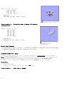
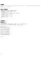
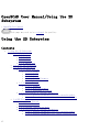
Example, a square base pyramid:
polyhedron(
points=[ [10,10,0],[10,-10,0],[-10,-10,0],[-10,10,0], // the four points at base
[0,0,10] ],
// the apex point
triangles=[ [0,1,4],[1,2,4],[2,3,4],[3,0,4],
// each triangle side
[1,0,3],[2,1,3] ]
// two triangles for square base
);
A simple polyhedron, square based pyramid
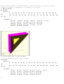
Ordering of triangle points An example of a more complex polyhedron, and showing how to
fix polyhedrons with badly oriented polygons.
When you select 'Thrown together' from the view menu and compile the design (not compile
and render!) you will see a preview with the mis-oriented polygons highlighted.
Unfortunately this highlighting is not possible in the OpenCSG preview mode because it would
interfere with the way the OpenCSG preview mode is implemented.)
17
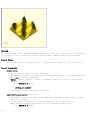
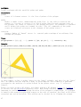
Below you can see the code and the picture of such a problematic polyhedron, the bad
polygons (triangles or compositions of triangles) are in pink.
// Bad polyhedron
polyhedron
(points = [
[0, -10, 60], [0, 10, 60], [0, 10, 0], [0,
60],
[10, -10, 50], [10, 10, 50], [10, 10, 30],
10, 50]
],
triangles = [
[0,2,3],
[0,1,2], [0,4,5], [0,5,1],
[6,8,9], [6,7,8], [6,10,11], [6,11,7],
[10,9,8], [0,3,9], [9,0,6], [10,6, 0],
[3,9,10], [3,10,4], [1,7,11], [1,11,5],
[1,8,2], [2,8,11], [2,11,5]
]
);
-10, 0], [60, -10, 60], [60, 10,
[10, -10, 30], [30, -10, 50], [30,
[5,4,2], [2,4,3],
[10,8,11],
[0,4,10],
[1,7,8],
Polyhedron with badly oriented polygons
A correct polyhedron would be the following:
polyhedron
(points = [
[0, -10, 60], [0, 10, 60], [0, 10, 0], [0, -10, 0], [60, -10, 60], [60, 10,
60],
[10, -10, 50], [10, 10, 50], [10, 10, 30], [10, -10, 30], [30, -10, 50], [30,
10, 50]
],
triangles = [
[0,3,2], [0,2,1], [4,0,5], [5,0,1], [5,2,4], [4,2,3],
[6,8,9], [6,7,8], [6,10,11],[6,11,7], [10,8,11],
[10,9,8], [3,0,9], [9,0,6], [10,6, 0],[0,4,10],
[3,9,10], [3,10,4], [1,7,11], [1,11,5], [1,8,7],
18
[2,8,1],
]
[8,2,11], [5,11,2]
);
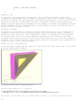
Beginner's tip:
If you don't really understand "orientation", try to identify the mis-oriented pink
triangles and then permute the references to the points vectors until you get it right. E.g.
in the above example, the third triangle ([0,4,5]) was wrong and we fixed it as [4,0,5]. In
addition, you may select "Show Edges" from the "View Menu", print a screen capture and
number both the points and the triangles. In our example, the points are annotated in black
and the triangles in blue. Turn the object around and make a second copy from the back if
needed. This way you can keep track.
Clockwise Technique:
Orientation is determined by clockwise indexing. This means that if you're looking at the
triangle (in this case [4,0,5]) from the outside you'll see that the path is clockwise
around the center of the face. The winding order [4,0,5] is clockwise and therefore good.
The winding order [0,4,5] is counter-clockwise and therefore bad. Likewise, any other
clockwise order of [4,0,5] works: [5,4,0] & [0,5,4] are good too. If you use the clockwise
technique, you'll always have your faces outside (outside of OpenSCAD, other programs do use
counter-clockwise as the outside though).
Think of it as a Left Hand Rule:
If you hold the triangle and the fingers of your hand curls is the same order as the points,
then your thumb points outwards.
Polyhedron with badly oriented polygons
Succinct description of a 'Polyhedron'
* Points define all of the points/vertices in the shape.
* Triangles is a list of triangles that connect up the points/vertices.
Each point, in the point list, is defined with a 3-tuple x,y,z position specification.
19
Points in the point list are automatically given an identifier starting at zero for use in
the triangle list (0,1,2,3,... etc).
Each triangle, in the triangle list, is defined by selecting 3 of the points (using the
point identifier) out of the point list.
e.g. triangles=[ [0,1,2] ] defines a triangle from the first point (points are zero
referenced) to the second point and then to the third point.
When looking at any triangle from the outside, the triangle must list their 3 points in a
clockwise order.
General
The text in its current form is incomplete.
Comments
OpenSCAD uses a programming language to create the models that are later displayed on the
screen. Comments are a way of leaving notes within the code (either to yourself or to future
programmers) describing how the code works, or what it does. Comments are not evaluated by
the compiler, and should not be used to describe self-evident code.
OpenSCAD uses C++-style comments:
// This is a comment
myvar = 10; // The rest of the line is a comment
/*
Multi-line comments
can span multiple lines.
*/
Variables
Variables in OpenSCAD are simply a name followed by an assignment via an expression (but see
below for an important note about variables!)
Example:
myvar = 5 + 4;
Currently it's not possible to do assignments at any place (the only places are file
top-level and module top-level). If you need it inside the for loop, for exemple, you need
to use the assign() module.
Undefined variable
A non assigned variable has a special value undef. It could be tested in conditional
expression, and returned by a function. Example
echo("Variable a is ", a); // output 'Variable a is undef'
if (a==undef) {
echo("Variable a is tested undefined");
}
function not_useful() = undef; // not really useful...
20
echo("Function returns ", not_useful()); // output 'Function returns undef'
Output Variable a is undef Variable a is tested undefined Function returns undef
Numeric
A variable could be a numerical value: integer, float...
Vectors
Variables can be grouped together into Vectors by using brackets. Vectors are useful when
dealing with X, Y, and Z coordinates or sizes.
Example
deck = [64, 89, 18];
cube(deck);
Output A cube with the sizes: X = 64, Y = 89, Z = 18.
Vectors selection
You can also refer to individual values in a vector with vector[number]. number starts from
0.
Example
deck = [64, 89, 18];
translate([0,0,deck[2]]) cube(deck);
Output The same cube as the previous example would be raised by 18 on the Z axis, since
vector indices are numbered [0,1,2] for [X,Y,Z] respectively.
Matrix
A matrix is a vector of vectors.
Example
mr = [
[cos(angle), -sin(angle)],
[sin(angle), cos(angle)]
];
Output Define a 2D rotation matrix.
Strings
Explicit double quotes or backslashes need to be escaped (\" and \\ respectively). Other
escaped special characters are newlines (\n), tabs (\t) and carriage returns (\r).
NB! This behavior is new since OpenSCAD-2011.04. You can upgrade old files using the
following sed command: sed 's/\\/\\\\/' non-escaped.scad > escaped.scad
Example:
echo("The quick brown fox \tjumps \"over\" the lazy dog.\rThe quick brown fox.\nThe
\\lazy\\ dog.");
Output:
21
ECHO: "The quick brown fox jumps "over" the lazy dog.
The quick brown fox.
The \lazy\ dog."
Output: in OpenSCAD version 2013.02.28
ECHO: "The quick brown fox \tjumps \"over\" the lazy dog.
The quick brown fox.\nThe \\lazy\\ dog."
Variables are set at compile-time, not run-time
Because OpenSCAD calculates its variable values at compile-time, not run-time, the last
variable assignment will apply everywhere the variable is used (with some exceptions,
mentioned below). It may be helpful to think of them as override-able constants rather than
as variables.
Example:
// The value of 'a' reflects only the last set value
a = 0;
echo(a);
a = 5;
echo(a);
Output
ECHO: 5
ECHO: 5
This also means that you can not reassign a variable inside an "if" block:
Example:
a=0;
if (a==0)
{
a=1; // <- this line will generate an error.
}
Output Compile Error
Exception #1
This behavior is scoped to either the root or to a specific call to a module, meaning you
can re-define a variable within a module without affecting its value outside of it. However,
all instances within that call will behave as described above with the last-set value being
used throughout.
Example:
p = 4;
test(5);
echo(p);
/*
* we start with p = 4. We step to the next command 'test(5)', which calls the 'test'
module.
* The 'test' module calculates two values for 'p', but the program will ONLY display the
final value.
* There will be two executions of echo(p) inside 'test' module, but BOTH will display '9'
22
because it is the FINAL
* calculated value inside the module. ECHO: 9
ECHO: 9
*
* Even though the 'test' module calculated value changes for 'p', those values remained
inside the module.
* Those values did not continue outside the 'test' module. The program has now finished
'test(5)' and moves to the next command 'echo(p)'.
* The call 'echo(p)' would normally display the original value of 'p'=4.
* Remember that the program will only show the FINAL values. It is the next set of
commands that produce the final values....which is ECHO: 6
*/
p = 6;
test(8);
echo(p);
/*
* We now see 'p=6', which is a change from earlier. We step to the next command
'test(8)', which calls the 'test' module.
* Again, the 'test' module calculates two values for 'p', but the program will ONLY
display the final value.
* There will be two executions of echo(p) inside 'test' module, but BOTH will display '12'
because it is the FINAL
* compiled value that was calculated inside the module.
* Therefore, both echo(p) statements will show the final value of '12' ;
* Remember that the 'test' module final values for 'p' will remain inside the module.
They do not continue outside the 'test' module.
* ECHO:12
ECHO: 12
*
* The program has now finished 'test(8)' and moves to the next command 'echo(p)'.
* Remember at compile that the pgm will show the FINAL values. The first value of
'echo(p)' would have showed a value of '4'...
* However, at compile time the final value of 'echo(p)' was actually '6'. Therefore, '6'
will be shown on both echo(p) statements.
* ECHO 6
*/
module test(q)
{
p = 2 + q;
echo(p);
p = 4 + q;
echo(p);
}
Output
ECHO:
ECHO:
ECHO:
ECHO:
ECHO:
ECHO:
9
9
6
12
12
6
While this appears to be counter-intuitive, it allows you to do some interesting things: For
instance, if you set up your shared library files to have default values defined as
23
variables at their root level, when you include that file in your own code, you can
're-define' or override those constants by simply assigning a new value to them.
Exception #2
See the assign, which provides for a more tightly scoped changing of values.
Getting input
Now we have variables, it would be nice to be able to get input into them instead of setting
the values from code. There are a few functions to read data from DXF files, or you can set
a variable with the -D switch on the command line.
Getting a point from a drawing
Getting a point is useful for reading an origin point in a 2D view in a technical drawing.
The function dxf_cross will read the intersection of two lines on a layer you specify and
return the intersection point. This means that the point must be given with two lines in the
DXF file, and not a point entity.
OriginPoint = dxf_cross(file="drawing.dxf", layer="SCAD.Origin",
origin=[0, 0], scale=1);
Getting a dimension value
You can read dimensions from a technical drawing. This can be useful to read a rotation
angle, an extrusion height, or spacing between parts. In the drawing, create a dimension
that does not show the dimension value, but an identifier. To read the value, you specify
this identifier from your script:
TotalWidth = dxf_dim(file="drawing.dxf", name="TotalWidth",
layer="SCAD.Origin", origin=[0, 0], scale=1);
For a nice example of both functions, see Example009 and the image on the homepage of
OpenSCAD.
Conditional and Iterator Functions
For Loop
Iterate over the values in a vector or range.
Vector version: for (variable=<vector>) <do_something> - <variable> is assigned to each
successive value in the vector
Range version: for (variable=<range>) <do_something>
Range: [<start>:<end>] - iterate from start to end inclusive. Also works if if <end> is
smaller than <start>
Range: [<start>:<increment>:<end>] - iterate from start to end with the given increment.
The increment can be a fraction. Note: The increment is given as an absolute value and
cannot be negative. If <end> is smaller than <start> the increment should remain unchanged.
Warning: If the increment is not an even divider of <end>-<start>, the iterator value for
the last iteration will be <end>-(<end>-<start> mod <increment>).
Nested loops : for ( variable1 = <range or vector>, variable2 = <range or vector> ) <do
something, using both variables>
for loops can be nested, just as in normal programs. A shorthand is that both iterations can
be given in the same for statement
24
Usage example 1 - iteration over a vector:
for (z = [-1, 1]) // two iterations, z = -1, z = 1
{
translate([0, 0, z])
cube(size = 1, center = false);
}
OpenSCAD iteration over a vector
Usage example 2a - iteration over a range:
for ( i = [0 : 5] )
{
rotate( i * 360 / 6, [1, 0, 0])
translate([0, 10, 0])
sphere(r = 1);
}
OpenSCAD iteration over a range)
Usage example 2b - iteration over a range specifying an increment:
// Note: The middle parameter in the range designation
// ('0.2' in this case) is the 'increment-by' value
// Warning: Depending on the 'increment-by' value, the
// real end value may be smaller than the given one.
for ( i = [0 : 0.2 : 5] )
{
rotate( i * 360 / 6, [1, 0, 0])
translate([0, 10, 0])
sphere(r = 1);
}
Usage example 3 - iteration over a vector of vectors
(rotation):
25
for(i = [ [ 0, 0,
0],
[ 10, 20, 300],
[200, 40, 57],
[ 20, 88, 57] ])
{
rotate(i)
cube([100, 20, 20], center = true);
}
OpenSCAD for loop (rotation)
Usage example 4 - iteration over a vector of vectors
(translation):
for(i = [ [ 0, 0, 0],
[10, 12, 10],
[20, 24, 20],
[30, 36, 30],
[20, 48, 40],
[10, 60, 50] ])
{
translate(i)
cube([50, 15, 10], center = true);
}
OpenSCAD for loop
(translation)
Nested loop example
for (xpos=[0:3], ypos = [2,4,6]) // do twelve iterations, using each xpos with each ypos
translate([xpos*ypos, ypos, 0]) cube([0.5, 0.5, 0.5]);
Intersection For Loop
Iterate over the values in a vector or range and take an intersection of the contents.
Note: intersection_for() is a work around because of an issue that you cannot get the
expected results using a combination of the standard for() and intersection()
statements. The reason is that for() do a implicit union() of the contents.
Parameters
<loop variable name>
Name of the variable to use within the for loop.
Usage example 1 - loop over a range:
26
intersection_for(n = [1 : 6])
{
rotate([0, 0, n * 60])
{
translate([5,0,0])
sphere(r=12);
}
}
OpenSCAD Intersection for
Usage example 2 - rotation :
intersection_for(i = [ [ 0,
[ 10, 20,
[200, 40,
[ 20, 88,
{
rotate(i)
cube([100, 20, 20], center
}
0,
0],
300],
57],
57] ])
= true);
OpenSCAD Intersection for (rotation)
If Statement
Conditionally evaluate a sub-tree.
Parameters
• The boolean expression that should be used as condition
NOTE:
Do not confuse the assignment operator '=' with the equal operator '=='
if (a=b) dosomething(); // WRONG - this will FAIL to be processed without any error
message
if (a==b) dosomething(); // CORRECT - this will do something if a equals b
Usage example:
if (x > y)
{
cube(size = 1, center = false);
} else {
cube(size = 2, center = true);
}
27
Assign Statement
Set variables to a new value for a sub-tree.
Parameters
• The variables that should be (re-)assigned
Usage example:
for (i = [10:50])
{
assign (angle = i*360/20, distance = i*10, r = i*2)
{
rotate(angle, [1, 0, 0])
translate([0, distance, 0])
sphere(r = r);
}
}
Mathematical Operators
The text in its current form is incomplete.
Scalar Arithmetical Operators
The scalar arithmetical operators take numbers as operands and produce a new number.
+ add
- subtract
* multiply
/ divide
% modulo
The "-" can also be used as prefix operator to negate a number.
Relational Operators
All relational operator take numbers as operands and produce a Boolean value. The equal and
not-equal operators can also compare Boolean values.
<
<=
==
!=
>=
>
less than
less equal
equal
not equal
greater equal
greater than
Logical Operators
All logical operators take Boolean values as operands and produce a Boolean value.
&& Logical AND
|| Logical OR
! Logical NOT
28
Conditional Operator
The ?: operator can be used to conditionally evaluate one or another expression. It works
like the ?: operator from the family of C-like programming languages.
? : Conditional operator
Usage Example:
a=1;
b=2;
c= a==b ? 4 : 5;
If a equals b, then c is set to 4, else c is set to 5.
The part "a==b" must be something that evaluates to a boolean value.
Vector-Number Operators
The vector-number operators take a vector and a number as operands and produce a new vector.
* multiply all vector elements by number
/ divide all vector elements by number
Vector Operators
The vector operators take vectors as operands and produce a new vector.
+ add element-wise
- subtract element-wise
The "-" can also be used as prefix operator to element-wise negate a vector.
Vector Dot-Product Operator
The vector dot-product operator takes two vectors as operands and produces a scalar.
* sum of vector element products
Matrix Multiplication
Multiplying a matrix by a vector, vector by matrix and matrix by matrix
* matrix/vector multiplication
Mathematical Functions
The text in its current form is incomplete.
Trigonometric Functions
cos
Mathematical cosine function of degrees. See Cosine
Parameters
<degrees>
29
Decimal. Angle in degrees.
Usage Example:
for(i=[0:36])
translate([i*10,0,0])
cylinder(r=5,h=cos(i*10)*50+60);
OpenSCAD Cos Function
sin
Mathematical sine function. See Sine
Parameters
<degrees>
Decimal. Angle in degrees.
Usage example 1:
for (i = [0:5]) {
echo(360*i/6, sin(360*i/6)*80, cos(360*i/6)*80);
translate([sin(360*i/6)*80, cos(360*i/6)*80, 0 ])
cylinder(h = 200, r=10);
}
Usage example 2:
for(i=[0:36])
translate([i*10,0,0])
cylinder(r=5,h=sin(i*10)*50+60);
OpenSCAD Sin Function
tan
Mathematical tangent function. See Tangent
Parameters
<degrees>
Decimal. Angle in degrees.
Usage example:
for (i = [0:5]) {
echo(360*i/6, tan(360*i/6)*80);
30
translate([tan(360*i/6)*80, 0, 0 ])
cylinder(h = 200, r=10);
}
acos
Mathematical arccosine, or inverse cosine, expressed in degrees. See: Inverse
trigonometric functions
asin
Mathematical arcsine, or inverse sine, expressed in degrees. See: Inverse trigonometric
functions
atan
Mathematical arctangent, or inverse tangent, function. Returns the principal value of the
arc tangent of x, expressed in degrees. See: Inverse trigonometric functions
atan2
Mathematical two-argument atan function, taking y as its first argument. Returns the
principal value of the arc tangent of y/x, expressed in degrees. See: atan2
Other Mathematical Functions
abs
Mathematical absolute value function. Returns the positive value of a signed decimal
number.
Usage examples:
abs(-5.0);
abs(0);
abs(8.0);
Results:
5.0
0.0
8.0
ceil
Mathematical ceiling function. ceil(x) is the smallest integer not less than x.
See: Ceil Function
echo(ceil(4.4),ceil(-4.4));
31
// produces ECHO: 5, -4
exp
Mathematical exp function. Returns the base-e exponential function of x, which is the
number e raised to the power x. See: Exponent
floor
Mathematical floor function. floor(x) = is the largest integer not greater than x
See: Floor Function
echo(floor(4.4),floor(-4.4));
// produces ECHO: 4, -5
ln
Mathematical natural logarithm. See: Natural logarithm
len
Mathematical length function. Returns the length of an array, a vector or a string
parameter.
Usage examples:
str1="abcdef"; len_str1=len(str1);
echo(str1,len_str1);
a=6; len_a=len(a);
echo(a,len_a);
array1=[1,2,3,4,5,6,7,8]; len_array1=len(array1);
echo(array1,len_array1);
array2=[[0,0],[0,1],[1,0],[1,1]]; len_array2=len(array2);
echo(array2,len_array2);
len_array2_2=len(array2[2]);
echo(array2[2],len_array2_2);
Results:
ECHO:
ECHO:
ECHO:
ECHO:
ECHO:
"abcdef", 6
6, undef
[1, 2, 3, 4, 5, 6, 7, 8], 8
[[0, 0], [0, 1], [1, 0], [1, 1]], 4
[1, 0], 2
This function allows (e.g.) the parsing of an array, a vector or a string.
Usage examples:
str2="4711";
for (i=[0:len(str2)-1])
echo(str("digit ",i+1,"
Results:
ECHO: "digit 1
ECHO: "digit 2
32
:
:
4"
7"
:
",str2[i]));
ECHO: "digit 3
ECHO: "digit 4
:
:
1"
1"
Note that the len() function is not defined when a simple variable is passed as the
parameter.
This is useful when handling parameters to a module, similar to how shapes can be defined as
a single number, or as an [x,y,z] vector; i.e. cube(5) or cube([5,5,5])
For example
module doIt(size) {
if (len(size) == undef) {
// size is a number, use it for x,y & z. (or could be undef)
do([size,size,size]);
} else {
// size is a vector, (could be a string but that would be stupid)
do(size);
}
}
doIt(5);
doIt([5,5,5]);
// equivalent to [5,5,5]
// similar to cube(5) v's cube([5,5,5])
log
Mathematical logarithm. See: Logarithm
lookup
Look up value in table, and linearly interpolate if there's no exact match. The first
argument is the value to look up. The second is the lookup table -- a vector of key-value
pairs.
Parameters
key
A lookup key
<key,value> array
keys and values
Notes
There is a bug where out-of-range keys will return the first value in the list. Newer
versions of Openscad should use the top or bottom end of the table as appropriate instead.
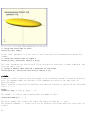
Usage example:
• Will create a sort of 3D chart made out of cylinders of different height.
33
function get_cylinder_h(p) = lookup(p, [
[ -200, 5 ],
[ -50, 20 ],
[ -20, 18 ],
[ +80, 25 ],
[ +150, 2 ]
]);
for (i = [-100:5:+100]) {
// echo(i, get_cylinder_h(i));
translate([ i, 0, -30 ]) cylinder(r1 = 6, r2 = 2, h = get_cylinder_h(i)*3);
}
max
Returns the maximum of the two parameters.
Parameters
<a>
Decimal.
<b>
Decimal.
Usage Example:
max(3.0,5.0);
max(8.0,3.0);
Results:
5.0
8.0
min
Returns the minimum of the two parameters.
Parameters
<a>
Decimal.
<b>
Decimal.
Usage Example:
min(3.0,5.0);
min(8.0,3.0);
Results:
3.0
3.0
34
OpenSCAD Lookup
Looking for mod
- it's not a function, see modulo operator (%)
norm
!!Note this function is not in 2013.01 and is pending pull request
https://github.com/openscad/openscad/pull/333.
Returns the euclidean norm of a vector. Note this returns is the actual numeric length while
len returns the number of elements in the vector or array.
Usage examples:
a=[1,2,3,4];
b="abcd";
c=[];
d="";
e=[[1,2,3,4],[1,2,3],[1,2],[1]];
echo(norm(a)); //5.47723
echo(norm(b)); //undef
echo(norm(c)); //0
echo(norm(d)); //undef
echo(norm(e[0])); //5.47723
echo(norm(e[1])); //3.74166
echo(norm(e[2])); //2.23607
echo(norm(e[3])); //1
Results:
ECHO:
ECHO:
ECHO:
ECHO:
ECHO:
ECHO:
ECHO:
ECHO:
5.47723
undef
0
undef
5.47723
3.74166
2.23607
1
pow
Mathematical power function.
Parameters
<base>
Decimal. Base.
<exponent>
Decimal. Exponent.
Usage examples:
for (i = [0:5]) {
translate([i*25,0,0]) {
cylinder(h = pow(2,i)*5, r=10);
echo (i, pow(2,i));
}
}
echo(pow(10,2)); // means 10^2 or 10*10
35
// result: ECHO: 100
echo(pow(10,3)); // means 10^3 or 10*10*10
// result: ECHO: 1000
rands
Random number generator. Generates a constant vector of pseudo random numbers, much like an
array. When generating only one number, you still call it with variable[0]
Parameters
min_value
Minimum value of random number range
max_value
Maximum value of random number range
value_count
Number of random numbers to return as a vector
seed_value (optional)
Seed value for random number generator for repeatable results.
Usage Examples:
// get a single number
single_rand = rands(0,10,1)[0];
echo(single_rand);
// get a vector of 4 numbers
seed=42;
random_vect=rands(5,15,4,seed);
echo( "Random Vector: ",random_vect);
sphere(r=5);
for(i=[0:3]) {
rotate(360*i/4) {
translate([10+random_vect[i],0,0])
sphere(r=random_vect[i]/2);
}
}
round
The "round" operator returns the greatest or least integer part, respectively, if the
numeric input is positive or negative.
Some examples:
round(x.5) = x+1.
round(x.49) = x.
round(-(x.5)) = -(x+1).
round(-(x.49)) = -x.
round(5.4); //-> 5
round(5.5); //-> 6
round(5.6); //-> 6
36
sign
Mathematical signum function. Returns a unit value that extracts the sign of a value see:
Signum function
Parameters
<x>
Decimal. Value to find the sign of.
Usage examples:
sign(-5.0);
sign(0);
sign(8.0);
Results:
-1.0
0.0
1.0
sqrt
Mathematical square root function.
Usage Examples:
translate([sqrt(100),0,0])sphere(100);
String Functions
The text in its current form is incomplete.
str
Convert all arguments to strings and concatenate.
Usage examples:
number=2;
echo ("This is ",number,3," and that's it.");
echo (str("This is ",number,3," and that's it."));
Results:
ECHO: "This is ", 2, 3, " and that's it."
ECHO: "This is 23 and that's it."
Also See search()
search() for text searching.
37
Transformations
Transformation affect the child nodes and as the name implies transforms them in various
ways such as moving/rotating or scaling the child. Cascading transformations are used to
apply a variety of transforms to a final child. Cascading is achieved by nesting statements
i.e.
transform()
transform()
child()
e.g.
rotate([45,45,45])
translate([10,20,30])
cube(10);
Note: child(...) is deprecated by children(...) in master. (2013.06 still uses
child(...)).
Transformations can be applied to a group of child nodes by using '{' & '}' to enclose the
subtree e.g.
translate(0,0,-5)
{
cube(10);
cylinder(r=5,h=10);
}
or the more compact
translate(0,0,-5) {
cube(10);
cylinder(r=5,h=10);
}
Advanced concept
As OpenSCAD uses different libraries to implement capabilities this can introduce some
inconsistencies to the F5 preview behaviour of transformations. Traditional transforms
(translate, rotate, scale, mirror & multimatrix) are performed using OpenGL in preview,
while other more advanced transforms, such as resize, perform a CGAL operation, behaving
like a CSG operation affecting the underlying object, not just transforming it. In
particular this can affect the display of modifier characters, specifically "#" and "%",
where the highlight may not display intuitively, such as highlighting the pre-resized
object, but highlighting the post-scaled object.
The text in its current form is incomplete.
scale
Scales its child elements using the specified vector. The argument name is optional.
Usage Example:
scale(v = [x, y, z]) { ... }
cube(10);
translate([15,0,0]) scale([0.5,1,2]) cube(10);
38
resize
resize() is available since OpenSCAD 2013.06. It modifies the size of the child object to
match the given x,y, and z.
There is a bug with shrinking in the 2013.06 release, that will be fixed in the next
release.
Usage Example:
// resize the sphere to extend 30 in x, 60 in y, and 10 in the z directions.
resize(newsize=[30,60,10]) sphere(r=10);
39
If x,y, or z is 0 then that dimension is left as-is.
// resize the 1x1x1 cube to 2x2x1
resize([2,2,0]) cube();
If the 'auto' parameter is set to true, it will auto-scale any 0-dimensions to match. For
example.
// resize the 1x2x0.5 cube to 7x14x3.5
resize([7,0,0], auto=true) cube([1,2,0.5]);
The 'auto' parameter can also be used if you only wish to auto-scale a single dimension, and
leave the other as-is.
// resize to 10x8x1. Note that the z dimension is left alone.
resize([10,0,0], auto=[true,true,false]) cube([5,4,1]);
rotate
Rotates its child a degrees about the origin of the coordinate system or around an arbitrary
axis. The argument names are optional if the arguments are given in the same order as
specified above.
When a rotation is specified for multiple axes then the rotation is applied in the following
order: x, y, z.
Usage:
rotate(a = deg, v = [x, y, z]) { ... }
For example, to flip an object upside-down, you might do this:
rotate(a=[0,180,0]) { ... }
The above example will rotate your object 180 degrees around the 'y' axis.
The optional argument 'v' allows you to set an arbitrary axis about which the object will be
rotated.
40
Example with arbitrary origin.
rotate(a=45, v=[1,1,0]) { ... }
This example will rotate your object 45 degrees around the axis defined by the vector
[1,1,0] i.e. 45 around X and 45 around Y.
If this is all a bit confusing, this might, or might not, help.
For the case of:
rotate([a, b, c]) { ... };
"a" is a rotation about the X axis, from the +Z axis, toward the -Y axis. NOTE: NEGATIVE Y.
"b" is a rotation about the Y axis, from the +Z axis, toward the +X axis.
"c" is a rotation about the Z axis, from the +X axis, toward the +Y axis.
Thus if "a" is fixed to zero, and "b" and "c" are manipulated appropriately, this is the
spherical coordinate system.
So, to construct a cylinder from the origin to some other point (x,y,z):
length=sqrt(pow(x, 2) + pow(y, 2) + pow(z, 2));
b=acos(z/length);
c= x==0 ? 90 :(x>0 ? atan(y/x): atan(y/x)+180);
rotate([0, b, c]) cylinder(h=length, r=0.5);
translate
Translates (moves) its child elements along the specified vector. The argument name is
optional.
IExample
translate(v = [x, y, z]) { ... }
cube(2,center = true);
translate([5,0,0])
sphere(1,center = true);
41
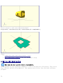
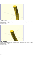
mirror
Mirrors the child element on a plane through the origin. The argument to mirror() is the
normal vector of a plane intersecting the origin through which to mirror the object.
Usage example:
mirror([ 0, 1, 0 ]) { ... }
•
mirror([1,0,0]);
•
mirror([1,1,0]);
42
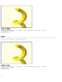
•
mirror([1,1,1]);
rotate([0,0,10]) cube([3,2,1]);
mirror([1,0,0]) translate([1,0,0]) rotate([0,0,10]) cube([3,2,1]);
multmatrix
Multiplies the geometry of all child elements with the given 4x4 transformation matrix.
Usage: multmatrix(m = [...]) { ... }
Example (translates by [10, 20, 30]):
multmatrix(m = [ [1, 0, 0, 10],
[0, 1, 0, 20],
[0, 0, 1, 30],
[0, 0, 0, 1]
]) cylinder();
Example (rotates by 45 degrees in XY plane and translates by [10,20,30]):
angle=45;
multmatrix(m = [ [cos(angle), -sin(angle), 0, 10],
[sin(angle), cos(angle), 0, 20],
[0, 0, 1, 30],
[0, 0, 0, 1]
]) union() {
cylinder(r=10.0,h=10,center=false);
cube(size=[10,10,10],center=false);
}
43
color
Displays the child elements using the specified RGB color + alpha value. This is only used
for the F5 preview as CGAL and STL (F6) do not currently support color. The alpha value will
default to 1.0 (opaque) if not specified.
Usage example:
color([r, g, b, a]) { ... }
Note that the r, g, b, a values are limited to floating point values in the range { 0.0 ...
1.0 } rather than the more traditional integers { 0 ... 255 }. However you can specify the
values as fractions, e.g. for R,G,B integers in {0 ... 255} you can use:
color([ R/255, G/255, B/255 ]) { ... }
As of the 2011.12 version, colors can also be chosen by name; name is not case sensitive.
For example, to create a red sphere, you can use this code:
color("red") sphere(5);
Alpha is also available with named colors:
color("Blue",0.5) cube(5);
The available color names are taken from the World Wide Web consortium's SVG color list. A
chart of the color names is as follows, (note that both spelling of grey/gray including
slategrey/slategray etc are valid):
Purples
Lavender
Thistle
Plum
Violet
Orchid
Fuchsia
Magenta
MediumOrchid
MediumPurple
BlueViolet
DarkViolet
DarkOrchid
DarkMagenta
Purple
Indigo
DarkSlateBlue
SlateBlue
MediumSlateBlue
Pinks
Pink
LightPink
HotPink
DeepPink
44
Greens
GreenYellow
Chartreuse
LawnGreen
Lime
LimeGreen
PaleGreen
LightGreen
MediumSpringGreen
SpringGreen
MediumSeaGreen
SeaGreen
ForestGreen
Green
DarkGreen
YellowGreen
OliveDrab
Olive
DarkOliveGreen
MediumAquamarine
DarkSeaGreen
LightSeaGreen
DarkCyan
Teal
Yellows
Gold
Yellow
LightYellow
LemonChiffon
LightGoldenrodYellow
PapayaWhip
Moccasin
PeachPuff
PaleGoldenrod
Khaki
DarkKhaki
Browns
Cornsilk
BlanchedAlmond
Bisque
NavajoWhite
Wheat
BurlyWood
Tan
RosyBrown
SandyBrown
Goldenrod
DarkGoldenrod
Whites
White
Snow
Honeydew
MintCream
Azure
AliceBlue
GhostWhite
WhiteSmoke
Seashell
Beige
OldLace
FloralWhite
Ivory
AntiqueWhite
Linen
LavenderBlush
MistyRose
Grays
Gainsboro
LightGrey
Silver
DarkGray
Gray
MediumVioletRed
PaleVioletRed
Blues
Aqua
Cyan
LightCyan
PaleTurquoise
Aquamarine
Turquoise
MediumTurquoise
DarkTurquoise
CadetBlue
SteelBlue
LightSteelBlue
PowderBlue
LightBlue
SkyBlue
LightSkyBlue
DeepSkyBlue
DodgerBlue
CornflowerBlue
RoyalBlue
Blue
MediumBlue
DarkBlue
Navy
MidnightBlue
Reds
IndianRed
LightCoral
Salmon
DarkSalmon
LightSalmon
Red
Crimson
FireBrick
DarkRed
45
Oranges
LightSalmon
Coral
Tomato
OrangeRed
DarkOrange
Orange
Peru
Chocolate
SaddleBrown
Sienna
Brown
Maroon
DimGray
LightSlateGray
SlateGray
DarkSlateGray
Black
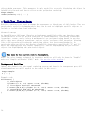
A 3-D multicolor sine wave
Here's a code fragment that draws a wavy multicolor object
for(i=[0:36])
{ for(j=[0:36])
{ color([0.5+sin(10*i)/2,0.5+sin(10*j)/2,0.5+sin(10*(i+j))/2])
translate([i,j,0])
cube(size=[1,1,11+10*cos(10*i)*sin(10*j)]);
}
}
Being that -1<=sin(x)<=1 then 0<=(1/2 + sin(x)/2)<=1 , allowing for the RGB components
assigned to color to remain within the {0,1} interval.
Chart based on "Web Colors" from Wikipedia
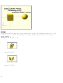
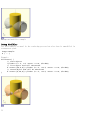
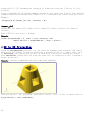
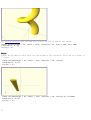
minkowski
A box and a cylinder
Minkowski sum of the box and cylinder
Displays the minkowski sum of child nodes.
46
Usage example:
Say you have a flat box, and you want a rounded edge. There are many ways to do this, but
minkowski is very elegant. Take your box, and a cylinder:
$fn=50;
cube([10,10,1]);
cylinder(r=2,h=1);
Then, do a minkowski sum of them:
$fn=50;
minkowski()
{
cube([10,10,1]);
cylinder(r=2,h=1);
}
hull
Two cylinders
Convex hull of two cylinders
Displays the convex hull of child nodes.
Usage example:
hull() {
translate([15,10,0]) circle(10);
circle(10);
}
CSG Modeling
The text in its current form is incomplete.
47
union
Creates a union of all its child nodes. This is the sum of all children.
Usage example:
union() {
cylinder (h = 4, r=1, center = true, $fn=100);
rotate ([90,0,0]) cylinder (h = 4, r=0.9, center = true, $fn=100);
}
Remark: union is implicit when not used. But it is mandatory, for example, in difference to
group first child nodes into one.
difference
Subtracts the 2nd (and all further) child nodes from the first one.
Usage example:
difference() {
cylinder (h = 4, r=1, center = true, $fn=100);
rotate ([90,0,0]) cylinder (h = 4, r=0.9, center = true, $fn=100);
}
48
intersection
Creates the intersection of all child nodes. This keeps the overlapping portion
Usage example:
intersection() {
cylinder (h = 4, r=1, center = true, $fn=100);
rotate ([90,0,0]) cylinder (h = 4, r=0.9, center = true, $fn=100);
}
render
Always calculate the CSG model for this tree (even in OpenCSG preview mode). The convexity
parameter specifies the maximum number of front sides (back sides) a ray intersecting the
49
object might penetrate. This parameter is only needed for correctly displaying the object in
OpenCSG preview mode and has no effect on the polyhedron rendering.
Usage example:
render(convexity = 1) { ... }
Modifier Characters
Modifier characters are used to change the appearance or behaviours of child nodes. They are
particularly useful in debugging where they can be used to highlight specific objects, or
include or exclude them from rendering.
Advanced concept
As OpenSCAD uses different libraries to implement capabilities this can introduce some
inconsistencies to the F5 preview behaviour of transformations. Traditional transforms
(translate, rotate, scale, mirror & multimatrix) are performed using OpenGL in preview,
while other more advanced transforms, such as resize, perform a CGAL operation, behaving
like a CSG operation affecting the underlying object, not just transforming it. In
particular this can affect the display of modifier characters, specifically "#" and "%",
where the highlight may not display intuitively, such as highlighting the pre-resized
object, but highlighting the post-scaled object.
The text in its current form is incomplete.
Note: The color changes triggered by character modifiers will only be shown in "Compile"
mode not "Compile and Render (CGAL)" mode. (As per the color section.)
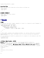
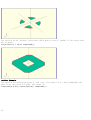
Background Modifier
Ignore this subtree for the normal rendering process and draw it in transparent gray (all
transformations are still applied to the nodes in this tree).
Usage example:
% { ... }
Example code:
difference() {
// start objects
cylinder (h = 4, r=1, center = true, $fn=100);
// first object that will subtracted
% rotate ([90,0,0]) cylinder (h = 4, r=0.3, center = true, $fn=100);
// second object that will be subtracted
% rotate ([0,90,0]) cylinder (h = 4, r=0.9, center = true, $fn=100);
}
50
Background modifier example
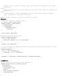
Debug Modifier
Use this subtree as usual in the rendering process but also draw it unmodified in
transparent pink.
Usage example:
# { ... }
Example:
difference() {
// start objects
cylinder (h = 4, r=1, center = true, $fn=100);
// first object that will subtracted
# rotate ([90,0,0]) cylinder (h = 4, r=0.3, center = true, $fn=100);
// second object that will be subtracted
# rotate ([0,90,0]) cylinder (h = 4, r=0.9, center = true, $fn=100);
}
51
OpenScad Debug Modifier example
Root Modifier
Ignore the rest of the design and use this subtree as design root.
Usage example:
! { ... }
Disable Modifier
Simply ignore this entire subtree.
Usage example:
* { ... }
Modules
usage
Defining your own module (roughly comparable to a macro or a function in other languages) is
a powerful way to reuse procedures.
module hole(distance, rot, size) {
rotate(a = rot, v = [1, 0, 0]) {
translate([0, distance, 0]) {
cylinder(r = size, h = 100, center = true);
}
}
}
In this example, passing in the parameters distance, rot, and size allow you to reuse this
functionality multiple times, saving many lines of code and rendering your program much
easier to read.
You can instantiate the module by passing values (or formulas) for the parameters just like
a C function call:
hole(0, 90, 10);
children (previously: child)
Remark: child(...) is, as of master, deprecated and should be replaced by
children(...), with same parameters (except child() without parameters that should be
replaced by children(0)). The latest stable release (2013.06) still uses child().
The child nodes of the module instantiation can be accessed using the children() statement
within the module:
Parameters
empty
select all the children
index
52
integer. select one child, at index value. index start at 0 and should be less than
$children-1.
vector
vector of integer. select children with index in vector. Index should be between 0 and
$children-1.
range
[<start>:<end>] or [<start>:<increment>:<end>]. select children between <start> to
<end>, incremented by <increment> (default 1).
Number of module children is accessed by $children variable.
Examples
Transfer all children to another module:
// rotate to other center point:
module rz(angle, center=undef) {
translate(center)
rotate(angle)
translate(-center)
children()
}
rz(15, [10,0]) sphere(30);
Use the first child, multiple time:
module lineup(num, space) {
for (i = [0 : num-1])
translate([ space*i, 0, 0 ]) children(0);
}
lineup(5, 65) sphere(30);
If you need to make your module iterate over all children you will need to make use of the
$children variable, e.g.:
module elongate() {
for (i = [0 : $children-1])
scale([10 , 1, 1 ]) children(i);
}
elongate() { sphere(30); cube([10,10,10]); cylinder(r=10,h=50); }
arguments
One can specify default values for the arguments:
module house(roof="flat",paint=[1,0,0]){
color(paint)
if(roof=="flat"){
translate([0,-1,0])
cube();
} else if(roof=="pitched"){
rotate([90,0,0])
53
linear_extrude(height=1)
polygon(points=[[0,0],[0,1],[0.5,1.5],[1,1],[1,0]],paths=[ [0,1,2,3,4] ]);
} else if(roof=="domical"){
translate([0,-1,0])
union(){
translate([0.5,0.5,1]) sphere(r=0.5,$fn=20);
cube();
}
}
}
And then use one of the following ways to supply the arguments
union(){
house();
translate([2,0,0]) house("pitched");
translate([4,0,0]) house("domical",[0,1,0]);
translate([6,0,0]) house(roof="pitched",paint=[0,0,1]);
translate([8,0,0]) house(paint=[0,0,0],roof="pitched");
translate([10,0,0]) house(roof="domical");
translate([12,0,0]) house(paint=[0,0.5,0.5]);
}
Importing Geometry
The text in its current form is incomplete.
import
Imports a file for use in the current OpenSCAD model
Parameters
<file>
A string containing the path to the STL or DXF file.
Usage examples:
import("example012.stl");
Notes: In the latest version of OpenSCAD, import() is now used for importing both 2D (DXF
for extrusion) and 3D (STL) files.
import_stl
<DEPRECATED.. Use the command import instead..>
Imports an STL file for use in the current OpenSCAD model
Parameters
<file>
A string containing the path to the STL file to include.
<convexity>
54
Integer. The convexity parameter specifies the maximum number of front sides (back
sides) a ray intersecting the object might penetrate. This parameter is only needed for
correctly displaying the object in OpenCSG preview mode and has no effect on the
polyhedron rendering.
Usage examples:
import_stl("example012.stl", convexity = 5);
Include Statement
The text in its current form is incomplete.
For including code from external files in OpenSCAD, there are two commands available:
• include <filename> acts as if the contents of the included file were written in
the including file, and
• use <filename> imports modules and functions, but does not execute any commands
other than those definitions.
Library files are searched for in the same folder as the design was open from, or in the
library folder of the OpenSCAD installation. You can use a relative path specification to
either. If they lie elsewhere you must give the complete path. Newer versions have
predefined user libraries, see the OpenSCAD_User_Manual/Libraries page, which also documents
a number of library files included in OpenSCAD.
Windows and Linux/Mac use different separators for directories. Windows uses \, e.g.
directory\file.ext, while the others use /, e.g. directory/file.ext. This could lead to
cross platform issues. However OpenSCAD on Windows correctly handles the use of /, so using
/ in all include or use statements will work on all platforms.
Using include <filename> allows default variables to be specified in the library. These
defaults can be overridden in the main code. An openscad variable only has one value during
the life of the program. When there are multiple assignments it takes the last value, but
assigns when the variable is first created. This has an effect when assigning in a library,
as any variables which you later use to change the default, must be assigned before the
include statement. See the second example below.
A library file for generating rings might look like this (defining a function and providing
an example):
ring.scad:
module ring(r1, r2, h) {
difference() {
cylinder(r = r1, h = h);
translate([ 0, 0, -1 ]) cylinder(r = r2, h = h+2);
}
}
ring(5, 4, 10);
Including the library using
include <ring.scad>;
rotate([90, 0, 0]) ring(10, 1, 1);
would result in the example ring being shown in addition to the rotated ring, but
55
use <ring.scad>;
rotate([90, 0, 0]) ring(10, 1, 1);
only shows the rotated ring.
Default variables in an include can be overridden, for example
lib.scad
i=1;
k=3;
module x() {
echo("hello world");
echo("i=",i,"j=",j,"k=",k);
}
hello.scad
j=4;
include <lib.scad>;
x();
i=5;
x();
k=j;
x();
Produces the following
ECHO:
ECHO:
ECHO:
ECHO:
ECHO:
ECHO:
"hello world"
"i=", 5, "j=", 4, "k=", 4
"hello world"
"i=", 5, "j=", 4, "k=", 4
"hello world"
"i=", 5, "j=", 4, "k=", 4
However, placing j=4; after the include fails, producing
ECHO:
ECHO:
ECHO:
ECHO:
ECHO:
ECHO:
"hello world"
"i=", 5, "j=", 4, "k=", undef
"hello world"
"i=", 5, "j=", 4, "k=", undef
"hello world"
"i=", 5, "j=", 4, "k=", undef
Other Language Features
The text in its current form is incomplete.
Special variables
All variables starting with a '$' are special variables The semantic is similar to the
special variables in lisp: they have dynamic instead of lexical scoping.
What that means is that they're effectively automatically passed onward as arguments.
Comparing a normal with a special variable:
56
normal=2;
module doesnt_pass_it()
{
echo(normal); }
module normal_mod()
{
doesnt_pass_it(); }
normal_mod(normal=1); //Should echo 2
$special=3; $another=5;
module passes_it()
{
echo($special, $another); }
module special_mod()
{
$another=6;
passes_it();
}
special_mod($special=4); //Should echo 4,6
So basically it is useful when you do not want to pass many parameters all the time.
$fa, $fs and $fn
The $fa, $fs and $fn special variables control the number of facets used to generate an arc:
$fa is the minimum angle for a fragment. Even a huge circle does not have more fragments
than 360 divided by this number. The default value is 12 (i.e. 30 fragments for a full
circle). The minimum allowed value is 0.01. Any attempt to set a lower value will cause a
warning.
$fs is the minimum size of a fragment. Because of this variable very small circles have a
smaller number of fragments than specified using $fa. The default value is 2. The minimum
allowed value is 0.01. Any attempt to set a lower value will cause a warning.
$fn is usually 0. When this variable has a value greater than zero, the other two variables
are ignored and full circle is rendered using this number of fragments. The default value is
0.
When $fa and $fs are used to determine the number of fragments for a circle, then OpenSCAD
will never use less than 5 fragments.
This is the C code that calculates the number of fragments in a circle:
int get_fragments_from_r(double r, double fn, double fs, double fa)
{
if (r < GRID_FINE) return 3;
if (fn > 0.0) return (int)(fn >= 3 ? fn : 3);
return (int)ceil(fmax(fmin(360.0 / fa, r*2*M_PI / fs), 5));
}
Spheres are first sliced into as many slices as the number of fragments being used to render
a circle of the sphere's radius, and then every slice is rendered into as many fragments as
are needed for the slice radius. You might have recognized already that the pole of a sphere
is usually a pentagon. This is why.
The number of fragments for a cylinder is determined using the greater of the two radii.
The method is also used when rendering circles and arcs from DXF files.
You can generate high resolution spheres by resetting the $fX values in the instantiating
module:
57
$fs = 0.01;
sphere(2);
or simply by passing the special variable as parameter:
sphere(2, $fs = 0.01);
You can even scale the special variable instead of resetting it:
sphere(2, $fs = $fs * 0.01);
$t
The $t variable is used for animation. If you enable the animation frame with view->animate
and give a value for "FPS" and "Steps", the "Time" field shows the current value of $t. With
this information in mind, you can animate your design. The design is recompiled every
1/"FPS" seconds with $t incremented by 1/"Steps" for "Steps" times, ending at either $t=1 or
$t=1-1/steps.
If "Dump Pictures" is checked, then images will be created in the same directory as the
.scad file, using the following $t values, and saved in the following files:
•
•
•
•
•
•
•
$t=0/Steps filename="frame00001.png"
$t=1/Steps filename="frame00002.png
$t=2/Steps filename="frame00003.png"
. . .
$t=1-3/Steps filename="frame<Steps-2>.png"
$t=1-2/Steps filename="frame<Steps-1>.png"
$t=1-1/Steps filename="frame00000.png"
Or, for other values of Steps, it follows this pattern:
•
•
•
•
•
•
•
•
$t=0/Steps filename="frame00001.png"
$t=1/Steps filename="frame00002.png
$t=2/Steps filename="frame00003.png"
. . .
$t=1-3/Steps filename="frame<Steps-2>.png"
$t=1-2/Steps filename="frame<Steps-1>.png"
$t=1-1/Steps filename="frame<Steps-0>.png"
$t=1-0/Steps filename="frame00000.png"
Which pattern it chooses appears to be an unpredictable, but consistent, function of Steps.
For example, when Steps=4, it follows the first pattern, and outputs a total of 4 files.
When Steps=3, it follows the second pattern, and also outputs 4 files. It will always output
either Steps or Steps+1 files, though it may not be predictable which. When finished, it
will wrap around and recreate each of the files, looping through and recreating them
forever.
$vpr and $vpt
These contain the current viewport rotation and translation - at the time of doing the
rendering. Moving he viewport does not update them. During an animation they are updated for
each frame.
• $vpr shows rotation
58
• $vpt shows translation (i.e. won't be affected by rotate and zoom)
It's not possible to write to them and thus change the viewport parameters (although that
could be a decent enough idea).
Example
cube([10,10,$vpr[0]/10]);
which makes the cube change size based on the view angle, if an animation loop is active
(which does not need to use the $t variable)
You can also make bits of a complex model vanish as you change the view.
The menu command Edit - Paste Viewport Rotation/Translation copies the current value of the
viewport, but not the current $vpr or $vpt.
User-Defined Functions
Define a function for code readability and re-use.
Recursive function calls are supported, necessitating the use of the Conditional Operator
"... ? ... : ... "
Usage examples:
my_d=20;
function r_from_dia(my_d) = my_d / 2;
echo("Diameter ", my_d, " is radius ", r_from_dia(my_d));
//recursion - find the sum of the values in a vector (array)
// from the start (or s'th element) to the i'th element - remember elements are zero based
function sumv(v,i,s=0) = (i==s ? v[i] : v[i] + sumv(v,i-1,s));
vec=[ 10, 20, 30, 40 ];
echo("sum vec=", sumv(vec,2,1)); // is 20+30=50
Echo Statements
This function prints the contents to the compilation window (aka Console). Useful for
debugging code. Also see the String function str().
The OpenSCAD console supports a subset of HTML markup language. See here for details.
Usage examples:
my_h=50;
my_r=100;
echo("This is a cylinder with h=", my_h, " and r=", my_r);
cylinder(h=my_h, r=my_r);
echo("<b>Hello</b> <i>Qt!</i>");
Shows in the Console as
ECHO:Hello Qt!
59
Render
Forces the generation of a mesh even in preview mode. Useful when the boolean operations
become too slow to track.
Needs description.
Usage examples:
render(convexity = 2) difference() {
cube([20, 20, 150], center = true);
translate([-10, -10, 0])
cylinder(h = 80, r = 10, center = true);
translate([-10, -10, +40])
sphere(r = 10);
translate([-10, -10, -40])
sphere(r = 10);
}
Surface
Example 1:
//surface.scad
surface(file = "surface.dat", center = true, convexity = 5);
%translate([0,0,5])cube([10,10,10], center =true);
#surface.dat
10 9 8 7 6 5 5 5 5 5
9 8 7 6 6 4 3 2 1 0
8 7 6 6 4 3 2 1 0 0
7 6 6 4 3 2 1 0 0 0
6 6 4 3 2 1 1 0 0 0
6 6 3 2 1 1 1 0 0 0
6 6 2 1 1 1 1 0 0 0
6 6 1 0 0 0 0 0 0 0
3 1 0 0 0 0 0 0 0 0
3 0 0 0 0 0 0 0 0 0
Result:
60
Example 2
// example010.dat generated using octave:
// d = (sin(1:0.2:10)' * cos(1:0.2:10)) * 10;
// save("example010.dat", "d");
intersection() {
surface(file = "example010.dat", center = true, convexity = 5);
rotate(45, [0, 0, 1]) surface(file = "example010.dat", center = true, convexity = 5);
}
61
Search
The search() function is a general-purpose function to find one or more (or all) occurrences
of a value or list of values in a vector, string or more complex list-of-list construct.
Search Usage
search( match_value , string_or_vector [, num_returns_per_match [, index_col_num ] ] );
Search Arguments
• match_value
• Can be a single value or vector of values.
• Strings are treated as vectors-of-characters to iterate over; the search function
does not search for substrings.
• Note: If match_value is a vector of strings, search will look for exact string
matches.
• See Example 9 below.
• string_or_vector
• The string or vector to search for matches.
• num_returns_per_match (default: 1)
• By default, search only looks for one match per element of match_value to return
as a list of indices
• If num_returns_per_match > 1, search returns a list of lists of up to
num_returns_per_match index values for each element of match_value.
• See Example 8 below.
62
• If num_returns_per_match = 0, search returns a list of lists of all matching
index values for each element of match_value.
• See Example 6 below.
• index_col_num (default: 0)
• When string_or_vector is a vector-of-vectors, multidimensional table or more
complex list-of-lists construct, the match_value may not be found in the first
(index_col_num=0) column.
• See Example 5 below for a simple usage example.
Search Usage Examples
See example023.scad included with OpenSCAD for a renderable example.
Index values return as list
Example
Code
search("a","abcdabcd");
1
Result
[0]
2
search("e","abcdabcd");
[]
3
search("a","abcdabcd",0);
[[0,4]]
4
search("a",[ ["a",1],["b",2],["c",3],["d",4],
["a",5],["b",6],["c",7],["d",8],["e",9] ], 0);
[[0,4]] (see also
Example 6 below)
Search on different column; return Index values
Example 5:
search(3,[ ["a",1],["b",2],["c",3],["d",4],["a",5],["b",6],["c",7],["d",8],["e",3] ], 0,
1);
Returns:
[2,8]
Search on list of values
Example 6: Return all matches per search vector element.
search("abc",[ ["a",1],["b",2],["c",3],["d",4],["a",5],["b",6],["c",7],["d",8],["e",9] ],
0);
Returns:
[[0,4],[1,5],[2,6]]
Example 7: Return first match per search vector element; special case return vector.
search("abc",[ ["a",1],["b",2],["c",3],["d",4],["a",5],["b",6],["c",7],["d",8],["e",9] ],
1);
63
Returns:
[0,1,2]
Example 8: Return first two matches per search vector element; vector of vectors.
search("abce",[ ["a",1],["b",2],["c",3],["d",4],["a",5],["b",6],["c",7],["d",8],["e",9] ],
2);
Returns:
[[0,4],[1,5],[2,6],[8]]
Search on list of strings
Example 9:
lTable2=[ ["cat",1],["b",2],["c",3],["dog",4],["a",5],["b",6],["c",7],["d",8],["e",9],
["apple",10],["a",11] ];
lSearch2=["b","zzz","a","c","apple","dog"];
l2=search(lSearch2,lTable2);
echo(str("Default list string search (",lSearch2,"): ",l2));
Returns
ECHO: "Default list string search ([\"b\", \"zzz\", \"a\", \"c\", \"apple\", \"dog\"]):
[1, [], 4, 2, 9, 3]"
Getting the right results
// workout which vectors get the results
v=[ ["O",2],["p",3],["e",9],["n",4],["S",5],["C",6],["A",7],["D",8] ];
//
echo(v[0]);
// -> ["O",2]
echo(v[1]);
// -> ["p",3]
echo(v[1][0],v[1][1]);
// -> "p",3
echo(search("p",v));
// find "p" -> [1]
echo(search("p",v)[0]);
// -> 1
echo(search(9,v,0,1));
// find 9 -> [2]
echo(v[search(9,v,0,1)[0]]);
// -> ["e",9]
echo(v[search(9,v,0,1)[0]][0]);
// -> "e"
echo(v[search(9,v,0,1)[0]][1]);
// -> 9
echo(v[search("p",v,1,0)[0]][1]);
// -> 3
echo(v[search("p",v,1,0)[0]][0]);
// -> "p"
echo(v[search("d",v,1,0)[0]][0]);
// "d" not found -> undef
echo(v[search("D",v,1,0)[0]][1]);
// -> 8
OpenSCAD Version
version() and version_num() will return OpenSCAD version number.
• The version() function will return the OpenSCAD version as a vector, e.g. [2011, 09,
23]
• The version_num() function will return the OpenSCAD version as a number, e.g. 20110923
64
OpenSCAD User Manual/Using the 2D
Subsystem
< OpenSCAD User Manual
This page may need to be reviewed for quality.
Using the 2D Subsystem
Contents
• 1 Using the 2D Subsystem
• 1.1 2D Primitives
• 1.1.1 square
• 1.1.2 circle
• 1.1.3 polygon
• 1.1.4 import_dxf
• 1.2 3D to 2D Projection
• 1.3 2D to 3D Extrusion
• 1.3.1 Linear Extrude
• 1.3.1.1 Usage
• 1.3.1.2 Twist
• 1.3.1.3 Center
• 1.3.1.4 Mesh Refinement
• 1.3.1.5 Scale
• 1.3.2 Rotate Extrude
• 1.3.2.1 Examples
• 1.3.2.2 Mesh Refinement
• 1.3.2.3 Extruding a Polygon
• 1.3.3 Description of extrude parameters
• 1.3.3.1 Extrude parameters for all extrusion modes
• 1.3.3.2 Extrude parameters for linear extrusion only
• 1.4 DXF Extrusion
• 1.4.1 Linear Extrude
• 1.4.2 Rotate Extrude
• 1.4.3 Getting Inkscape to work
• 1.4.4 Description of extrude parameters
• 1.4.4.1 Extrude parameters for all extrusion modes
• 1.4.4.2 Extrude parameters for linear extrusion only
65
2D Primitives
All 2D primitives can be transformed with 3D transformations. Usually used as part of a 3D
extrusion. Although infinitely thin, they are rendered with a 1 thickness.
square
Creates a square at the origin of the coordinate system. When center is true the square will
be centered on the origin, otherwise it is created in the first quadrant. The argument names
are optional if the arguments are given in the same order as specified in the parameters
Parameters
size
Decimal or 2 value array. If a single number is given, the result will be a square with
sides of that length. If a 2 value array is given, then the values will correspond to
the lengths of the X and Y sides. Default value is 1.
center
Boolean. This determines the positioning of the object. If true, object is centered at
(0,0). Otherwise, the square is placed in the positive quadrant with one corner at
(0,0). Defaults to false.
Example
square ([2,2],center = true);
circle
Creates a circle at the origin of the coordinate system. The argument name is optional.
Parameters
r
Decimal. This is the radius of the circle. The resolution of the circle will be based
on the size of the circle. If you need a small, high resolution circle you can get
around this by making a large circle, then scaling it down by an appropriate factor, or
you could set $fn or other special variables. Default value is 1.
d
Decimal. This is the diameter of the circle. The resolution of the circle will be based
on the size of the circle. If you need a small, high resolution circle you can get
around this by making a large circle, then scaling it down by an appropriate factor, or
you could set $fn or other special variables. Default value is 1.
Examples
circle();
// uses default radius, r=1
circle(r = 10);
circle(d = 20);
scale([1/100, 1/100, 1/100]) circle(200); // this will create a high resolution circle with
a 2mm radius
circle(2, $fn=50); // Another way to create a high-resolution circle with a radius of 2.
66
polygon
Create a polygon with the specified points and paths.
Parameters
points
vector of 2 element vectors, ie. the list of points of the polygon
paths
Either a single vector, enumerating the point list, ie. the order to traverse the
points, or, a vector of vectors, ie a list of point lists for each seperate curve of
the polygon. The latter is required if the polygon has holes. The parameter is optional
and if omitted the points are assumed in order. (The 'pN' components of the paths
vector are 0-indexed references to the elements of the points vector.)
convexity
Integer. Number of "inward" curves, ie. expected path crossings of an arbitraty line
through the polygon.
Usage
polygon(points = [ [x, y], ... ], paths = [ [p1, p2, p3..], ...], convexity = N);
Example
polygon(points=[[0,0],[100,0],[0,100],[10,10],[80,10],[10,80]], paths=[[0,1,2],[3,4,5]]);
Polygon example
In this example, we have 6 points (three for the "outer" triangle, and three for the "inner"
one). We connect each one with two 2 path. In plain English, each element of a path must
correspond to the position of a point defined in the points vector, e.g. "1" refers to
[100,0].
Notice: In order to get a 3D object, you either extrude a 2D polygon (linear or (rotation )
or directly use the polyhedron primitive solid. When using extrusion to form solids, its
important to realize that the winding direction of the polygon is significant. If a polygon
is wound in the wrong direction with respect to the axis of rotation, the final solid (after
extrusion) may end up invisible. This problem can be checked for by flipping the polygon
67
using scale([-1,1]) (assuming that extrusion is being done about the Z axis as it is by
default).
Notice: Althought the 2D drawing commands operate in axes labeled as X and Y, the extrusion
commands implicitly translate these objects in X-Z coordinates and rotate about the Z axis.
Example:
polygon([[0,0],[10,90],[11,-10]], convexity = N);
import_dxf
DEPRECATED: The import_dxf() module will be removed in future releases. Use import()
instead.
Read a DXF file and create a 2D shape.
Example
linear_extrude(height = 5, center = true, convexity = 10)
import_dxf(file = "example009.dxf", layer = "plate");
3D to 2D Projection
Using the projection() function, you can create 2d drawings from 3d models, and export
them to the dxf format. It works by projecting a 3D model to the (x,y) plane, with z at 0.
If cut=true, only points with z=0 will be considered (effectively cutting the object),
with cut=false, points above and below the plane will be considered as well (creating a
proper projection).
Example: Consider example002.scad, that comes with OpenSCAD.
Then you can do a 'cut' projection, which gives you the 'slice' of the x-y plane with z=0.
projection(cut = true) example002();
68
You can also do an 'ordinary' projection, which gives a sort of 'shadow' of the object onto
the xy plane.
projection(cut = false) example002();
Another Example
You can also use projection to get a 'side view' of an object. Let's take example002, and
move it up, out of the X-Y plane, and rotate it:
translate([0,0,25]) rotate([90,0,0]) example002();
69
Now we can get a side view with projection()
projection() translate([0,0,25]) rotate([90,0,0]) example002();
Links:
• example021.scad from Clifford Wolf's site.
• More complicated example from Giles Bathgate's blog
2D to 3D Extrusion
The text in its current form is incomplete.
It is possible to use extrusion commands to convert 2D objects to 3D objects. This can be
done with the built-in 2D primitives, like squares and circles, but also with arbitrary
polygons.
70
Linear Extrude
Linear Extrusion is a modeling operation that takes a 2D polygon as input and extends it in
the third dimension. This way a 3D shape is created.
Usage
linear_extrude(height = fanwidth, center = true, convexity = 10, twist = -fanrot, slices =
20, scale = 1.0) {...}
You must use parameter names due to a backward compatibility issue.
If the extrusion fails for a non-trival 2D shape, try setting the convexity parameter (the
default is not 10, but 10 is a "good" value to try). See explanation further down.
Twist
Twist is the number of degrees of through which the shape is extruded. Setting the parameter
twist = 360 will extrude through one revolution. The twist direction follows the left hand
rule.
0° of Twist
linear_extrude(height = 10, center = true, convexity = 10, twist = 0)
translate([2, 0, 0])
circle(r = 1);
71
-100° of Twist
linear_extrude(height = 10, center = true, convexity = 10, twist = -100)
translate([2, 0, 0])
circle(r = 1);
100° of Twist
linear_extrude(height = 10, center = true, convexity = 10, twist = 100)
translate([2, 0, 0])
circle(r = 1);
72
-500° of Twist
linear_extrude(height = 10, center = true, convexity = 10, twist = -500)
translate([2, 0, 0])
circle(r = 1);
Center
Center determines if the object is centered after extrusion, so it does not extrude up and
down from the center as you might expect.
center = true
linear_extrude(height = 10, center = true, convexity = 10, twist = -500)
translate([2, 0, 0])
circle(r = 1);
73
center = false
linear_extrude(height = 10, center = false, convexity = 10, twist = -500)
translate([2, 0, 0])
circle(r = 1);
Mesh Refinement
The slices parameter can be used to improve the output.
linear_extrude(height = 10, center = false, convexity = 10, twist = 360, slices = 100)
translate([2, 0, 0])
circle(r = 1);
74
The special variables $fn, $fs and $fa can also be used to improve the output.
linear_extrude(height = 10, center = false, convexity = 10, twist = 360, $fn = 100)
translate([2, 0, 0])
circle(r = 1);
Scale
Scales the 2D shape by this value over the height of the extrusion. Scale can be a scalar or
a vector:
linear_extrude(height = 10, center = true, convexity = 10, scale=3)
translate([2, 0, 0])
circle(r = 1);
linear_extrude(height = 10, center = true, convexity = 10, scale=[1,5], $fn=100)
translate([2, 0, 0])
circle(r = 1);
75
Rotate Extrude
A rotational extrusion is a Linear Extrusion with a twist, literally. Unfortunately, it can
not be used to produce a helix for screw threads as the 2D outline must be normal to the
axis of rotation, ie they need to be flat in 2D space.
Examples
A simple torus can be constructed using a rotational extrude.
rotate_extrude(convexity = 10)
translate([2, 0, 0])
circle(r = 1);
76
Mesh Refinement
Increasing the number of fragments that the 2D shape is composed of will improve the quality
of the mesh, but take longer to render.
rotate_extrude(convexity = 10)
translate([2, 0, 0])
circle(r = 1, $fn = 100);
The number of fragments used by the extrusion can also be increased.
rotate_extrude(convexity = 10, $fn = 100)
translate([2, 0, 0])
circle(r = 1, $fn = 100);
Extruding a Polygon
Extrusion can also be performed on polygons with points chosen by the user.
Here is a simple polygon. Note it has been rotated 90 degrees to show how the rotation will
77
look, the rotate_extrude() needs it flat.
rotate([90,0,0]) polygon( points=[[0,0],[2,1],[1,2],[1,3],[3,4],[0,5]] );
Here is the same polygon, rotationally extruded, and with the mesh refinement set to 200.
The polygon must touch the rotational axis for the extrusion to work, i.e. you can't build a
polygon rotation with a hole.
rotate_extrude($fn=200) polygon( points=[[0,0],[2,1],[1,2],[1,3],[3,4],[0,5]] );
For more information on polygons, please see: 2D Primitives: Polygon.
Description of extrude parameters
Extrude parameters for all extrusion modes
Integer. The convexity parameter specifies the maximum number of front sides
(back sides) a ray intersecting the object might penetrate.
convexity
78
This parameter is only needed for correctly displaying the object in OpenCSG
preview mode and has no effect on the polyhedron rendering.
This image shows a 2D shape with a convexity of 4, as the ray indicated in red crosses the
2D shape a maximum of 4 times. The convexity of a 3D shape would be determined in a similar
way. Setting it to 10 should work fine for most cases.
Extrude parameters for linear extrusion only
height
center
twist
slices
scale
The extrusion height
If true the solid will be centered after extrusion
The extrusion twist in degrees
Similar to special variable $fn without being passed down to the child 2D shape.
Scales the 2D shape by this value over the height of the extrusion.
DXF Extrusion
The text in its current form is incomplete.
With the import() and extrusion statements it is possible to convert 2D objects read from
DXF files to 3D objects.
Linear Extrude
Example of linear extrusion of a 2D object imported from a DXF file.
linear_extrude(height = fanwidth, center = true, convexity = 10)
import (file = "example009.dxf", layer = "fan_top");
Rotate Extrude
Example of rotational extrusion of a 2D object imported from a DXF file.
rotate_extrude(convexity = 10, twist = -fanrot)
import (file = "example009.dxf", layer = "fan_side", origin = fan_side_center);
79
Getting Inkscape to work
Inkscape is an open source drawing program. Tutorials for transferring 2d DXF drawings from
Inkscape to OpenSCAD are available here:
• http://repraprip.blogspot.com/2011/05/inkscape-to-openscad-dxf-tutorial.html (Very
simple)
• http://tonybuser.com/?tag=inkscape (More complicated, involves conversion to
Postscript)
• http://www.damonkohler.com/2010/11/inkscape-dxf-openscad-makerbot.html (Better Better
DXF Plugin for Inkscape)
Description of extrude parameters
Extrude parameters for all extrusion modes
scale
convexity
file
layer
origin
FIXME
See 2D to 3D Extrusion
The name of the DXF file to extrude [DEPRECATED]
The name of the DXF layer to extrude [DEPRECATED]
[x,y] coordinates to use as the drawing's center, in the units specified in the
DXF file [DEPRECATED]
Extrude parameters for linear extrusion only
height
center
twist
slices
The extrusion height
If true, extrusion is half up and half down. If false, the section is extruded up.
The extrusion twist in degrees
FIXME
OpenSCAD User Manual/STL Import and Export
< OpenSCAD User Manual
This page may need to be reviewed for quality.
Import and Export
A prime ingredient of any 3D design flow is the ability to import from and export to other
tools. The STL file format is currently the most common format used.
80
Import
The text in its current form is incomplete.
import
Imports a file for use in the current OpenSCAD model
Parameters
<file>
A string containing the path to the STL or DXF file.
Usage examples:
import("example012.stl");
Notes: In the latest version of OpenSCAD, import() is now used for importing both 2D (DXF
for extrusion) and 3D (STL) files.
import_stl
<DEPRECATED.. Use the command import instead..>
Imports an STL file for use in the current OpenSCAD model
Parameters
<file>
A string containing the path to the STL file to include.
<convexity>
Integer. The convexity parameter specifies the maximum number of front sides (back
sides) a ray intersecting the object might penetrate. This parameter is only needed for
correctly displaying the object in OpenCSG preview mode and has no effect on the
polyhedron rendering.
Usage examples:
import_stl("example012.stl", convexity = 5);
STL Export
The text in its current form is incomplete.
STL Export
To export your design, select "Export as STL..." from the "Design" menu, then enter a
filename in the ensuing dialog box. Don't forget to add the ".stl" extension.
Trouble shooting:
After compile and render GCAL (F6), you may see that your design is simple: no. That's bad
news.
See line 8 in the following output from OpenSCAD 2010.02:
81
Parsing design (AST generation)...
Compiling design (CSG Tree generation)...
Compilation finished.
Rendering Polygon Mesh using CGAL...
Number of vertices currently in CGAL cache: 732
Number of objects currently in CGAL cache: 12
Top level object is a 3D object:
Simple:
no
<*****************
Valid:
yes
Vertices:
22
Halfedges:
70
Edges:
35
Halffacets:
32
Facets:
16
Volumes:
2
Total rendering time: 0 hours, 0 minutes, 0 seconds
Rendering finished.
When you try to export this to .STL you will get a message like:
Object isn't a valid 2-manifold! Modify your design..
"Manifold" means that it is "water tight" and that there are no holes in the geometry. In a
valid 2-manifold each edge must connect exactly two facets. That means that the program must
be able to connect a face with an object. E.g. if you use a cube of height 10 to carve out
something from a wider cube of height 10, it is not clear to which cube the top or the
bottom belongs. So make the small extracting cube a bit "longer" (or "shorter"):
difference() {
// original
cube (size = [2,2,2]);
// object that carves out
# translate ([0.5,0.5,-0.5]) {
cube (size = [1,1,3]);
}
}
82
Correct use of difference
Here is a more tricky little example taken from the OpenSCAD Forum (retrieved 15:13, 22
March 2010 (UTC)):
module example1() {
cube([20, 20, 20]);
translate([-20, -20, 0])
cube([50, 50, 5], center
}
module example2() {
cube([20.1, 20.1, 20]);
translate([-20, -20, 0])
cube([50, 50, 5], center
}
Example1 would render like this:
83
cube([20, 20, 20]);
= true);
cube([20.1, 20.1, 20]);
= true);
A not valid 2-manifold cube (simple = no)
The example1 module is not a valid 2-manifold because both cubes are sharing one edge. They
touch each other but do not intersect.
Example2 is a valid 2-manifold because there is an intersection. Now the construct meets
the 2-manifold constraint stipulating that each edge must connect exactly two facets.
Pieces you are subtracting must extend past the original part. (OpenSCAD Tip: Manifold Space
and Time, retrieved 18:40, 22 March 2010 (UTC)).
For reference, another situation that causes the design to be non-exportable is when two
faces that are each the result of a subtraction touch. Then the error message comes up.
difference () {
cube ([20,10,10]);
translate ([10,0,0]) cube (10);
}
difference () {
cube ([20,10,10]);
cube (10);
}
simply touching surfaces is correctly handled.
translate ([10,0,0]) cube (10);
cube (10);
OpenSCAD User Manual/Commented Example
Projects
84
< OpenSCAD User Manual
The latest reviewed version was checked on 16 January 2013. There is 1 pending change
awaiting review.
The text in its current form is incomplete.
Dodecahedron
//create a dodecahedron by intersecting 6 boxes
module dodecahedron(height)
{
scale([height,height,height]) //scale by height parameter
{
intersection(){
//make a cube
cube([2,2,1], center = true);
intersection_for(i=[0:4]) //loop i from 0 to 4, and intersect results
{
//make a cube, rotate it 116.565 degrees around the X axis,
//then 72*i around the Z axis
rotate([0,0,72*i])
rotate([116.565,0,0])
cube([2,2,1], center = true);
}
}
}
}
//create 3 stacked dodecahedra
//call the module with a height of 1 and move up 2
translate([0,0,2])dodecahedron(1);
//call the module with a height of 2
dodecahedron(2);
//call the module with a height of 4 and move down 4
translate([0,0,-4])dodecahedron(4);
The Dode
from the
Bounding Box
// Rather kludgy module for determining bounding box from intersecting projections
module BoundingBox()
{
intersection()
{
translate([0,0,0])
linear_extrude(height = 1000, center = true, convexity = 10, twist = 0)
projection(cut=false) intersection()
{
rotate([0,90,0])
linear_extrude(height = 1000, center = true, convexity = 10, twist = 0)
projection(cut=false)
rotate([0,-90,0])
children(0);
85
Bound
Ellip
rotate([90,0,0])
linear_extrude(height = 1000, center = true, convexity = 10, twist = 0)
projection(cut=false)
rotate([-90,0,0])
children(0);
}
rotate([90,0,0])
linear_extrude(height = 1000, center = true, convexity = 10, twist = 0)
projection(cut=false)
rotate([-90,0,0])
intersection()
{
rotate([0,90,0])
linear_extrude(height = 1000, center = true, convexity = 10, twist = 0)
projection(cut=false)
rotate([0,-90,0])
children(0);
rotate([0,0,0])
linear_extrude(height = 1000, center = true, convexity = 10, twist = 0)
projection(cut=false)
rotate([0,0,0])
children(0);
}
}
}
// Test module on ellipsoid
translate([0,0,40]) scale([1,2,3]) sphere(r=5);
BoundingBox() scale([1,2,3]) sphere(r=5);
OpenSCAD User Manual/Using an external
Editor with OpenSCAD
< OpenSCAD User Manual
This page may need to be reviewed for quality.
86
OpenSCAD session using emacs as an external editor
Contents
•
•
•
•
1
2
3
4
Why use an
How to use
Support of
Additional
external editor
an external editor
external editors
benefits
Why use an external editor
Many people prefer to use a certain editor. They are used to the feature set and know the
keybindings. OpenSCADs editor is functional and simplistic but might lack features people
know from other editors.
How to use an external editor
OpenScad is able to check for changes of files and automatically recompile if a file change
occurs. To use this feature enable "Design->Automatic Reload and Compile"
Once the feature is activated, just load the scad file within OpenSCAD as usual
("File->Open.."). After that, open the scad file in your favorite editor too. Edit and work
on the scad file within the external editor. Whenever the file is saved to disk (from within
the external editor), OpenSCAD will recognize the file change and automatically recompiles
accordingly.
The internal editor can be hidden by minimizing the frame with the mouse or by selecting
"View->Hide editor".
87
Support of external editors
In principle all editors can be used. For some exist extensions/modes to provide features
for OpenSCAD.
• Emacs: OpenSCAD delivers a emacs mode for OpenSCAD files. Use the link or the emacs
package management ELPA and the emacs marmelade repository.
• Kate: nerd256 provides a kate syntax file for OpenSCAD. See Instructions tab in
Thingiverse to install it. You could create also a kate External tool to open OpenSCAD
with the current file with script openscad %directory/%filename
• VIM: vim.org provides a VIM syntax file for OpenSCAD. Also, a dictionary file is
here.
Additional benefits
Beside of using an external editor of choice, this solutions enables the flexible usage of
multi-monitor set-ups. One can have one monitor set-up to depict the 3D object on the entire
screen and a second monitor for the editor and other tools.
OpenSCAD User Manual/Using OpenSCAD in a
command line environment
< OpenSCAD User Manual
This page may need to be reviewed for quality.
OpenSCAD can not only be used as a GUI, but also handles command line arguments. Its usage
line says:
OpenSCAD 2013.05+ has these options:
openscad
[ -o output_file [ -d deps_file ] ]\
[ -m make_command ] [ -D var=val [..] ] [ --render ] \
[ --camera=translatex,y,z,rotx,y,z,dist | \
--camera=eyex,y,z,centerx,y,z ] \
[ --imgsize=width,height ] [ --projection=(o)rtho|(p)ersp] \
filename
Earlier releases had only these:
openscad [ -o output_file [ -d deps_file ] ] \
[ -m make_command ] [ -D var=val [..] ] filename
The usage on OpenSCAD version 2011.09.30 (now deprecated) was:
openscad [ { -s stl_file | -o off_file | -x dxf_file } [ -d deps_file ] ]\
[ -m make_command ] [ -D var=val [..] ] filename
Contents
• 1 Export options
88
• 2
• 3
• 4
• 5
• 1.1 Camera and image output
Constants
Command to build required files
Makefile example
• 4.1 Automatic targets
Windows notes
Export options
When called with the -o option, OpenSCAD will not start the GUI, but execute the given file
and export the to the output_file in a format depending on the extension (.stl / .off /
.dxf, .csg).
Some versions use -s/-d/-o to determine the output file format instead check with "openscad
--help".
If the option -d is given in addition to an export command, all files accessed while
building the mesh are written in the argument of -d in the syntax of a Makefile.
Camera and image output
For 2013.05+, the option to output a .png image was added. There are two types of cameras
available for the generation of images.
The first camera type is a 'gimbal' camera that uses Euler angles, translation, and a camera
distance, like OpenSCAD's GUI viewport display at the bottom of the OpenSCAD window.
!!! There is a bug in the implementation of cmdline camera, where the rotations do not match
the numbers in the GUI. This will be fixed in an upcoming release so that the GUI and
cmdline camera variables will work identically.
The second camera type is a 'vector' camera, with an 'eye' camera location vector and a
'lookat' center vector.
--imgsize chooses the .png dimensions and --projection chooses orthogonal or perspective, as
in the GUI.
By default, cmdline .png output uses Preview mode (f5) with OpenCSG. For some situations it
will be desirable instead to use the full render, with CGAL. This is done by adding
'--render' as an option.
Constants
In order to pre-define variables, use the -D option. It can be given repeatedly. Each
occurrence of -D must be followed by an assignment. Unlike normal OpenSCAD assignments,
these assignments don't define variables, but constants, which can not be changed inside the
program, and can thus be used to overwrite values defined in the program at export time.
If you want to assign the -D variable to anther variable, the -D variable MUST be
initialised in the main .scad program
param1=0;
// must be initalised
len=param1; // param1 passed via -D on cmd-line
echo(len,param);
without the first line len wound be undefined.
The right hand sides can be arbitrary OpenSCAD expressions, including mathematical
operations and strings. Be aware that strings have to be enclosed in quotes, which have to
89
be escaped from the shell. To render a model that takes a quality parameter with the value
"production", one has to run
openscad -o my_model_production.stl -D 'quality="production"' my_model.scad
Command to build required files
In a complex build process, some files required by an OpenSCAD file might be currently
missing, but can be generated, for example if they are defined in a Makefile. If OpenSCAD is
given the option -m make, it will start make file the first time it tries to access a
missing file.
Makefile example
The -d and -m options only make sense together. (-m without -d would not consider modified
dependencies when building exports, -d without -m would require the files to be already
built for the first run that generates the dependencies.)
Here is an example of a basic Makefile that creates an .stl file from an .scad file of the
same name:
# explicit wildcard expansion suppresses errors when no files are found
include $(wildcard *.deps)
%.stl: %.scad
openscad -m make -o $@ -d [email protected] $<
When make my_example.stl is run for the first time, it finds no .deps files, and will
just depend on my_example.scad; since my_example.stl is not yet preset, it will be
created unconditionally. If OpenSCAD finds missing files, it will call make to build them,
and it will list all used files in my_example.stl.deps.
When make my_example.stl is called subsequently, it will find and include
my_example.stl.deps and check if any of the files listed there, including
my_example.scad, changed since my_example.stl was built, based on their time stamps.
Only if that is the case, it will build my_example.stl again.
Automatic targets
When building similar .stl files from a single .scad file, there is a way to automate that
too:
# match "module foobar() { // `make` me"
TARGETS=$(shell sed '/^module [a-z0-9_-]*().*make..\?me.*$$/!d;s/module //;s/().*/.stl/'
base.scad)
all: ${TARGETS}
# auto-generated .scad files with .deps make make re-build always. keeping the
# scad files solves this problem. (explanations are welcome.)
.SECONDARY: $(shell echo "${TARGETS}" | sed 's/\.stl/.scad/g')
# explicit wildcard expansion suppresses errors when no files are found
include $(wildcard *.deps)
%.scad:
echo -n 'use <base.scad>\n$*();' > $@
90
%.stl: %.scad
openscad -m make -o $@ -d [email protected] $<
All objects that are supposed to be exported automatically have to be defined in base.scad
in an own module with their future file name (without the ".stl"), and have a comment like
"// make me" in the line of the module definition. The "TARGETS=" line picks these out
of the base file and creates the file names. These will be built when make all (or make,
for short) is called.
As the convention from the last example is to create the .stl files from .scad files of the
same base name, for each of these files, an .scad file has to be generated. This is done in
the "%.scad:" paragraph; my_example.scad will be a very simple OpenSCAD file:
use <base.scad>
my_example();
The ".SECONDARY" line is there to keep make from deleting the generated .scad files. If
it deleted it, it would not be able to automatically determine which files need no rebuild
any more; please post ideas about what exactly goes wrong there (or how to fix it better) on
the talk page!
Windows notes
On Windows, openscad.com should be called from the command line as a wrapper for
openscad.exe. This is because Openscad uses the 'devenv' solution to the Command-Line/GUI
output issue. Typing 'openscad' at the cmd.exe prompt will, by default, call the .com
program wrapper.
OpenSCAD User Manual/Building OpenSCAD from
Sources
< OpenSCAD User Manual
Most users will want to download the pre-compiled binary installation packages from the main
http://www.openscad.org website.
However, you can compile the OpenSCAD source yourself if you so desire. It will allow you to
experiment with new features and bug fixes in the development versions. It will also expose
you to certain accidental breaks and bugs during the development process. It is highly
recommended you join the openscad developers mailing list if you are experimenting with the
latest source code.
This page provides general information. You can find specific step-by-step instructions on
the following pages:
•
•
•
•
•
91
OpenSCAD
OpenSCAD
OpenSCAD
OpenSCAD
OpenSCAD
User
User
User
User
User
Manual/Building on Linux/UNIX
Manual/Cross-compiling for Windows on Linux or Mac OS X
Manual/Building on Windows
Manual/Building on Mac OS X
Manual/Submitting patches
Contents
• 1 Structure of OpenSCAD
• 1.1 OpenCSG
• 1.2 CGAL
• 1.3 CGAL and GMPQ
• 1.4 Throwntogether
• 1.5 Source Code Notes
• 1.6 Library notes
• 2 Submitting Patches
Structure of OpenSCAD
OpenSCAD, as of 2011, relies heavily on two other projects: the OpenCSG library and the CGAL
geometry library. OpenCSG uses special tricks of OpenGL graphics cards to quickly produce
2-d 'previews' of Computational Solid Geometry operations. This is the normal 'F5' mode.
CGAL on the other hand is a Geometry library that actually calculates intersections & unions
of objects, allowing for .stl export to 3d printers. This is the 'F6' mode.
In theory, though, the backend libraries could be replaced. OpenSCAD is a text-based CAD
program. It doesn't matter what 'backend' is used for it's geometry as long as it works
properly and provides useful functions. Discussions on the mailing list have mentioned the
possibility of the OpenCASCADE library instead of CGAL, for example.
OpenCSG
OpenCSG is based largely around special algorithms that can 'fake' the presentation of
Computational Solid Geometry operations (subtraction, intersection, union) on a 2d screen.
The two main algorithms it uses are SCS and Goldfeather, selectable in OpenSCAD from the
'preferences' menu. The algorithms work by breaking down CSG operations into parts, and then
rendering the parts into an OpenGL graphics buffer using special features such as an
off-screen OpenGL Framebuffer Object (or Pbuffers), as well as making extensive use of the
OpenGL Stencil Buffer and Depth Buffer.
OpenCSG also requires that the objects be 'normalized'. For example, if your code says to
start with a cube, subtract a sphere, add a diamond, add a cylinder, add two more spheres,
and subtract a donut, this is not 'normalized'. Normalization forms the primitive objects
into a 'tree' where each 'leaf' consists of a 'positive' and 'negative' object. OpenSCAD
does this normalization itself, as can be seen in the log window during OpenCSG previews.
The Normalized CSG tree is then passed to OpenCSG for rendering. Occasionally the
normalization process "blows up" and freezes the machine, making CGAL rendering the only way
to view an object. The number of objects during normalization is limited and can be changed
in OpenSCAD preferences.
OpenCSG has it's own example source code that comes with the program. It can help you to
learn about the various OpenCSG rendering options.
Links:
• OpenCSG main website
• Freenix 2005 slideshow on OpenCSG, Goldfeather, and Normalization
• Freenix 2005 paper, more detail on Goldfeather, Normalization, etc.
92
CGAL
CGAL is the Computational Geometry Algorithm Library. It contains a large collection of
Geometry algorithms and methods by which objects can be represented. It calculates the
actual 'point sets' of 3d objects, which enables the output of 3d formats like STL.
OpenSCAD uses two main features of CGAL - the Nef Polyhedra and the 'ordinary' Polyhedra. It
also uses various other functions like Triangulation &c. But the main data structures are
the Nef and the 'ordinary' Polyhedra.
Nef Polyhedra
According to wikipedia's Nef Polyhedron article, Nef Polyhedrons are named after Walter Nef,
who wrote a book on Polyhedrons named "Beiträge zur Theorie der Polyeder" published in 1978
by Herbert Lang, in Bern, Switzerland. A very rough explanation of the theory goes like
this: imagine you can create a 'plane' that divides the universe in half. Now, imagine you
can 'mark' one side to be the 'inside' and the other side to be the 'outside'. Now imagine
you take several of these planes, and arrange them, for example, as if they were walls of a
room, and a ceiling and a floor. Now lets just imagine the 'inside' of all of these planes and now imagine that you do an 'intersection' operation on them - like a venn diagram or any
other boolean operation on sets. You will find that this 'intersection' forms a cuboid from the outside it just looks like a box. This box is the Nef Polyhedron. In other terms,
you have created a polyhedron by doing boolean operations on "half spaces" - halves of the
universe.
Why would you go to all this trouble? Why not just use plain old 'points in space' and
triangle faces and be done with it? Well, Nef Polyhedrons have certain properties that make
boolean operations on them work better than boolean operations between meshes-- in theory.
CGAL's Nef Polyhedron code calculates the resulting 3 dimensional points of the new shapes
generated when you perform CSG operations. Let's take example 4 from OpenSCAD's example
programs. It is a cube with a sphere subtracted from it. The actual coordinates of the
polygons that make up that 'cage' shape are calculated by CGAL by calculating the
intersections and unions of the 'half spaces' involved. Then it is converted to an 'ordinary
polyhedron'. This can then be transformed into .stl (stereolithography) files for output to
a 3d-printing system.
Ordinary Polyhedra
CGAL's Nef Polyhedron is not the only type of Polyhedron representation inside of CGAL.
There is also the more basic "CGAL Polyhedron_3", which here is called 'ordinary' Polyhedra.
In fact, many of OpenSCAD's routines will convert a CGAL Nef Polyhedron into an 'ordinary'
CGAL Polyhedron_3. The trick here is that 'ordinary' Polyhedron_3's have limits. Namely
this: "the polyhedral surface is always an orientable and oriented 2-manifold with border
edges". That basically means it only deals with 'water tight' surfaces that don't have
complicated issues like self-intersection, isolated lines and points, etc. A more exact
explanation can be found here: http://www.carliner-remes.com/jacob/math/project/math.htm
The conversion between Nef Polyhedra and 'plain' Polyhedron_3 can sometimes result in
problems when using OpenSCAD.
issues
In theory CGAL is seamless and consistent. In actuality, there are some documentation flaws,
bugs, etc. OpenSCAD tries to wrap calls to CGAL with exception-catchers so the program won't
crash every time the user tries to compile something.
Another interesting note is comparing the 2d and 3d polyhedra and nef polyhedra functions.
There is no way to transform() a 2d nef polyhedron, for example, so OpenSCAD implemented
it's own. There is no easy way to convert a Nef polyhedron from 2d to 3d. The method for
'iterating through' the 2d data structure is also entirely different from the way you
93
iterate through the 3d data structure - one uses an 'explorer' while another provides a
bunch of circulators and iterators.
CGAL is also very slow to compile - as a library that is almost entirely headers, there is
no good way 'around' this other than to get a faster machine with more RAM, and possibly to
use the clang compiler instead of GCC. Paralell building ( make -j ) can help but that wont
speed up the compile of a single file you are working on if it uses a feature like CGAL
Minkowski sums.
CGAL and GMPQ
CGAL allows a user to pick a 'kernel' - the type of numbers to be used in the underlying
data structures. Many 3d rendering engines just use floating-point numbers - but this can be
a problem when doing geometry because of roundoff errors. CGAL offers other kernels and
number types, for example the GMPQ number type, from the GNU GMP project. This is basically
the set of Rational Numbers.
Rational Numbers (the ratio of two integers) are an advantage in Geometry because you can do
alot of things to them without any rounding error - including scaling. For example, take the
number 1/3. You cannot represent that exactly in IEEE floating point on a PC. It comes out
to 0.3333... going on to infinity. The same goes for numbers like 0.6 - there is actually no
binary representation of the decimal number 0.6 in a finite number of binary digits.
The binary number system on a finite-bit machine is not 'closed' under division. You can
divide one finite-digit binary floating point number by another and get a number thats not,
itself, a finite-digit binary floating point number. Like, 6, divided by 10, yielding 0.6.
In fact this is not just a problem of binary numbers, it's a problem of any number system
that uses a decimal point and has a finite number of digits - from the Ten-based system
(decimals) to Hexadecimal to Binary to anything. But with Rationals this doesn't happen. You
can divide any rational number by any other rational and you wind up with another Rational and it is not infinite and there is no rounding involved. So 'scaling' down a 3d object made
of Rational Points results in 0 rounding error. 'scaling' down a 3d object of floating point
numbers will frequently result in rounding error.
Another nice feature of rationals is that if you have two lines whose end-points (or
rise/run, or line equation) are rational numbers, their intersection point will also be a
rational number with no rounding error. Finite Floating Point numbers cannot guarantee that
(because of the division involved in solving the line equations). Note that this is very
helpful for a program like CGAL that is dealing with lots of intersections between planes.
Imagine doing an 'interesection' between two faceted spheres offset by their radius, for
example.
The downside is that Rationals are slow. Most of the optimization made in the hardware of
modern computer CPUs is based around the idea of dealing with ordinary floating-point or
integer numbers, not with ratios of integers - integers which can be larger than the size of
'long int' on the machine. (also called Big Ints).
When doing debugging, if you are inside the code and you do something like 'std::cout <<
vertex->point().x()" you will get a ratio of two integers, not a floating point. For
floating conversion, you have to use CGAL::to_double( vertex->point().x() ); You may notice,
sometimes, that your 'double' conversion, with its chopping off and rounding, it might show
that two points are equal, when printing the underlying GMPQ will show that, in fact, the
same two points have different coordinates entirely.
Lastly, within OpenSCAD, it must be noted that it's default number type is typically C++
'double' (floating point). Thus, even though you may have 'perfect' CGAL objects represented
with rationals, OpenSCAD itself uses a lot of floating point, and translates the floating
point back-and-forth to CGAL GMPQ during compilation (another area for slowdown).
94
Links:
•
•
•
•
•
CGAL's main website
Number represenation in CGAL
CGAL 3d Boolean operations on Nef Polyhedra (Notice any familiar colors?)
ordinary CGAL Polyhedron 3
Nef polyhedron, wikipedia
Throwntogether
The "Throwntogether" renderer is a "fall back" quick-preview renderer that OpenSCAD can use
if OpenCSG is not available. It should work on even the most minimal of OpenGL systems. It's
main drawback is that it renders negative spaces as big, opaque, green blocks instead of as
'cut outs' of the positive spaces. This can hide a lot of the internal detail of a shape and
make use of OpenSCAD more difficult. The 'intersection' command, for example, does not do
anything - it simply displays the full intersection shapes as if they were a union. However,
by hitting 'F6' the user can still compile the object into CGAL and see the shape as it is
intended.
Under what circumstances does the program fall back to Throwntogether, instead of using
OpenCSG preview? In cases where the OpenGL machine does not support Stencil Buffers, and
cannot draw Offscreen images with "Framebuffer Objects" (FBOs). If the user finds that
OpenCSG support is buggy on their system, they can also manually switch to 'throwntogether'
mode through the menus.
Source Code Notes
Ifdefs
The design of the code is so that, in theory, CGAL and/or OpenCSG can be disabled or
enabled. In practice this doesn't always work and tweaking is needed. But if some day the
underlying engines were to be replaced, this feature of the code would greatly aid such a
transition.
Value
The Value class is OpenSCAD's way of representing numbers, strings, boolean variables,
vectors, &c. OpenSCAD uses this to bridge-the-gap between the .scad source code and the guts
of it's various engines. value.h and value.cc use the boost 'variant' feature (sort of like
C unions, but nicer).
node
You will notice that most important pieces derive from the AbstractNode class. Various
conventions and patterns are the same between different nodes, so when implementing new
features or fixing bugs, it can be helpful to simply look at the way things are done by
comparing nodes. For example transformnode.h and transform.cc show the basic setup of how
something like 'scale()' goes from source code (in a 'context') into a member variable of
the transformnode (node.matrix), which is then used by CGALEvaluator.cc to actually do a
'transform' on the 3d object data. This can be compared with colornode, lineartextrudenode,
etc.
Polyset
PolySet is a sort of 'inbetween' glue-class that represents 3d objects in various stages of
processing. All primitives are first created as a PolySet and then transformed later, if
necessary, into CGAL forms. OpenSCAD currently converts all import() into a PolySet, before
converting to CGAL Nef polyhedra, or CGAL 'ordinary' polyhedra.
95
DXF stuff
As of early 2013, OpenSCAD's 2d subsystem relies heavily on DXF format, an old format used
in Autocad and created by Autodesk in the 1980s. DXFData is sort of the equivalent of
PolySet for 2d objects - glue between various other 2d representations.
CGAL Nef Polyhedron
This class 'encapsulates' both 2d and 3d Nef polyhedrons. It contains useful functions like
the boolean operators, union, intersection, and even Minkowski sum. It is incredibly slow to
compile, mostly due to the CGAL minkowski header code being very large, so it has been
broken into separate .cc files. You may also note that pointers are generally avoided when
dealing with Nef polyhedra - instead boost::shared_ptr is used.
CGAL ordinary polyhedron
You may notice there is no class for 'ordinary' CGAL Polyhedron. That's correct. There
isn't. it's always just used 'as is', typically as an intermediate form between other
formats. As noted, the conversion to/from 'ordinary' can cause issues for 'non 2-manifold'
objects. CGAL's Polyhedron also is used for file export (see export.cc).
GUI vs tests
As of early 2013 OpenSCAD used two separate build systems. one for the GUI binary, and
another for regression testing. The first is based on Qmake and the second on Cmake. Adding
features may require someone to work with both of these systems. See doc/testing.txt for
more info on building and running the regression tests.
Library notes
QT
OpenSCAD's GUI uses the QT toolkit. However, for all non-gui code, the developers avoid QT
and use alternatives like boost::filesystem. This helps with certain things like modularity
and portability. As of mid 2013 it was possible to build the test suites entirely without
QT.
Other libraries & library versions
OpenSCAD also depends on Boost, the Eigen math library, and the GLEW OpenGL extension helper
library. In order to actually build OpenSCAD, and compile and run the self-diagnostic tests,
OpenSCAD also needs tools like 'git', 'cmake', and ImageMagick. Version numbers can be very
important. They are listed in a readme file in the root of the OpenSCAD source code. Using
libraries that are too old will result in an OpenSCAD that exhibits bizarre behavior or
crashes.
Submitting Patches
See http://en.wikibooks.org/wiki/OpenSCAD_User_Manual/Submitting_patches
OpenSCAD User Manual/Building on Linux/UNIX
< OpenSCAD User Manual
96
Contents
• 1 Prebuilt binary packages
• 2 Building OpenSCAD yourself
• 2.1 Installing dependencies
• 2.2 Building the dependencies yourself
• 2.3 Build the OpenSCAD binary
• 3 Compiling the test suite
• 4 Troubleshooting
• 4.1 Errors about incompatible library versions
• 4.2 OpenCSG didn't automatically build
• 4.3 CGAL didn't automatically build
• 4.4 Compiling is horribly slow and/or grinds the disk
• 4.5 BSD issues
• 4.6 Test suite problems
• 4.7 I moved the dependencies I built and now openscad won't run
• 5 Tricks and tips
• 5.1 Reduce space of dependency build
• 5.2 Preferences
• 5.3 Setup environment to start developing OpenSCAD in Ubuntu 11.04
• 5.4 The Clang Compiler
Prebuilt binary packages
As of 2013, prebuilt OpenSCAD packages are available on many recent Linux and BSD
distributions, including Debian, Ubuntu, Fedora, Arch, and NetBSD. Check your system's
package manager for details.
For Ubuntu systems you can also try chrysn's Ubuntu packages at his launchpad PPA, or you
can just copy/paste the following onto the command line:
sudo add-apt-repository ppa:chrysn/openscad
sudo apt-get update
sudo apt-get install openscad
His repositories for OpenSCAD and OpenCSG are here and here.
There is also a generic linux binary package at http://www.openscad.org that can be unpacked
and run from within most linux systems. It is self contained and includes the required
libraries.
Building OpenSCAD yourself
If you wish to build OpenSCAD for yourself, start by installing git on your system using
your package manager. Git is often packaged under the name 'scmgit' or 'git-core'. Then, get
the OpenSCAD source code
cd ~/
git clone https://github.com/openscad/openscad.git
cd openscad
Then get the MCAD library, which is now included with OpenSCAD binary distributions
97
git submodule init
git submodule update
Installing dependencies
Now download and install the dependency libraries and tools using your package manager. This
includes Qt4, CGAL, GMP, cmake, MPFR, boost, OpenCSG, GLEW, Eigen2, GCC C++ Compiler, Bison,
and Flex. OpenSCAD comes with a helper script that will try to fetch and install these
automatically for you (note: you must have 'sudo' working for this script to work).
./scripts/uni-get-dependencies.sh
Now check the version numbers against the openscad/README.md file to see if the version
numbers are high enough and that no packages were accidentally missed. OpenSCAD comes with
another helper script to assist in this process.
./scripts/check-dependencies.sh
(Note that this detects a 'lower bound' on GLEW, not the actual version you have)
If your system passes all checks, continue to the 'Building OpenSCAD' section below. If you
are missing libraries, try to search your package manager to see if it might have them under
different names. If your package manager has the package but it is just too old, then read
the next section on building your own dependencies.
Building the dependencies yourself
On systems that lack updated dependency libraries or tools, you can download and build your
own. As of 2013, OpenSCAD comes with scripts that can do this automatically, without
interfering with any system libraries, and without requiring root access, by putting
everything under $HOME/openscad_deps. (It however will not build X11, Qt4, gcc, bash or
other basics).
First, set up the environment variables (if you don't use bash, replace "source" with a
single ".")
source scripts/setenv-unibuild.sh
Then, download and build.
./scripts/uni-build-dependencies.sh
If you only need CGAL or OpenCSG, you can just run ' ./scripts/uni-build-dependencies.sh
cgal' or opencsg and it will only build a single library. The complete download and build
process can take anywhere from half an hour to several hours, depending on your network
connection speed and system speed. It is recommended to have at least 1.5 Gigabyte of free
disk space to do the full dependency build. Each time you log into a new shell and wish to
re-compile OpenSCAD you need to re-run the 'source scripts/setenv-unibuild.sh' script
After completion, re-check (while running under the same shell, with the same environment
variables set) to see if it worked.
./scripts/check-dependencies.sh
98
Build the OpenSCAD binary
Once you have either downloaded or built the dependencies, you can build OpenSCAD.
qmake
make
# or qmake-qt4, depending on your distribution
You can also install OpenSCAD to /usr/local/ if you wish. The 'openscad' binary will be put
under /usr/local/bin, the libraries and examples will be under something like
/usr/local/share/openscad possibly depending on your system. Note that if you have
previously installed a binary linux package of openscad, you should take care to delete
/usr/local/lib/openscad and /usr/local/share/openscad because they are not the same paths as
what the standard qmake-built 'install' target uses.
sudo make install
Note: on Debian-based systems create a package and install OpenSCAD using:
sudo checkinstall -D make install
If you prefer not to install you can run "./openscad" directly whilst still in the
~/openscad directory.
Compiling the test suite
OpenSCAD comes with over 740 regression tests. To build and run them, it is recommended to
first build the GUI version of OpenSCAD by following the steps above, including the
downloading of MCAD. Then, from the same login, run these commands:
cd tests
mkdir build && cd build
cmake ..
make
ctest -C All
The file 'openscad/doc/testing.txt' has more information. Full test logs are under
tests/build/Testing/Temporary. A pretty-printed index.html web view of the tests can
be found under a machine-specific subdirectory thereof and opened with a browser.
Troubleshooting
If you encounter any errors when building, please file an issue report at
https://github.com/openscad/openscad/issues/ .
Errors about incompatible library versions
This may be caused by old libraries living in /usr/local/lib like boost, CGAL, OpenCSG, etc,
(often left over from previous experiments with OpenSCAD). You are advised to remove them.
To remove, for example, CGAL, run rm -rf /usr/local/include/CGAL && rm -rf
/usr/local/lib/*CGAL*. Then erase $HOME/openscad_deps, remove your openscad source tree, and
99
restart fresh. As of 2013 OpenSCAD's build process does not advise nor require anything to
be installed in /usr/local/lib nor /usr/local/include.
Note that CGAL depends on Boost and OpenCSG depends on GLEW - interdependencies like this
can really cause issues if there are stray libraries in unusual places.
Another source of confusion can come from running from within an 'unclean shell'. Make sure
that you don't have LD_LIBRARY_PATH set to point to any old libraries in any strange places.
Also don't mix a Mingw windows cross build with your linux build process - they use
different environment variables and may conflict.
OpenCSG didn't automatically build
If for some reason the recommended build process above fails to work with OpenCSG, please
file an issue on the OpenSCAD github. In the meantime, you can try building it yourself.
wget http://www.opencsg.org/OpenCSG-1.3.2.tar.gz
sudo apt-get purge libopencsg-dev libopencsg1 # or your system's equivalent
tar -xvf OpenCSG-1.3.2.tar.gz
cd OpenCSG-1.3.2
# edit the Makefile and remove 'example'
make
sudo cp -d lib/lib* $HOME/openscad_deps/lib/
sudo cp include/opencsg.h $HOME/openscad_deps/include/
Note: on Debian-based systems (such as Ubuntu), you can add the 'install'
target to the OpenCSG Makefile, and then use checkinstall to create a clean .deb
package for install/removal/upgrade. Add this target to Makefile:
install:
# !! THESE LINES PREFIXED WITH ONE TAB, NOT SPACES !!
cp -d lib/lib* /usr/local/lib/
cp include/opencsg.h /usr/local/include/
ldconfig
Then:
sudo checkinstall -D make install
.. to create and install a clean package.
CGAL didn't automatically build
If this happens, you can try to compile CGAL yourself. It is recommended to install to
$HOME/openscad_deps and otherwise follow the build process as outlined above.
Compiling is horribly slow and/or grinds the disk
It is recommended to have at least 1.2 Gbyte of RAM to compile OpenSCAD. There are a few
workarounds in case you don't. The first is to use the experimental support for the Clang
Compiler (described below) as Clang uses much less RAM than GCC. Another workaround is to
edit the Makefile generated by qmake and search/replace the optimization flags (-O2) with
-O1 or blank, and to remove any '-g' debug flags from the compiler line, as well as '-pipe'.
100
If you have plenty of RAM and just want to speed up the build, you can try a paralell
multicore build with
make -jx
Where 'x' is the number of cores you want to use. Remember you need x times the amount of
RAM to avoid possible disk thrashing.
The reason the build is slow is because OpenSCAD uses template libraries like CGAL, Boost,
and Eigen, which use large amounts of RAM to compile - especially CGAL. GCC may take up 1.5
Gigabytes of RAM on some systems during the build of certain CGAL modules. There is more
information at StackOverflow.com.
BSD issues
The build instructions above are designed to work unchanged on FreeBSD and NetBSD. However
the BSDs typically require special environment variables set up to build any QT project you can set them up automatically by running
source ./scripts/setenv-unibuild.sh
NetBSD 5.x, requires a patched version of CGAL. It is recommended to upgrade to NetBSD 6
instead as it has all dependencies available from pkgin. NetBSD also requires the X Sets to
be installed when the system was created (or added later).
On OpenBSD it may fail to build after running out of RAM. OpenSCAD requires at least 1
Gigabyte to build with GCC. You may have need to be a user with 'staff' level access or
otherwise alter required system parameters. The 'dependency build' sequence has also not
been ported to OpenBSD so you will have to rely on the standard OpenBSD system package tools
(in other words you have to have root).
Test suite problems
Headless server
The test suite will try to automatically detect if you have an X11 DISPLAY environment
variable set. If not, it will try to automatically start Xvfb or Xvnc (virtual X
framebuffers) if they are available.
If you want to run these servers manually, you can attempt the following:
$ Xvfb :5 -screen 0 800x600x24 &
$ DISPLAY=:5 ctest
Alternatively:
$ xvfb-run --server-args='-screen 0 800x600x24' ctest
There are some cases where Xvfb/Xvnc won't work. Some older versions of Xvfb may fail and
crash without warning. Sometimes Xvfb/Xvnc have been built without GLX (OpenGL) support and
OpenSCAD won't be able to generate any images.
Image-based tests takes a long time, they fail, and the log says 'return -11'
Imagemagick may have crashed while comparing the expected images to the test-run generated
(actual) images. You can try using the alternate ImageMagick comparison method by by erasing
CMakeCache, and re-running cmake with -DCOMPARATOR=ncc. This will enable the Normalized
Cross Comparison method which is more stable, but possibly less accurate and may give false
positives or negatives.
101
Testing images fails with 'morphology not found" for ImageMagick in the log
Your version of imagemagick is old. Upgrade imagemagick, or pass -DCOMPARATOR=old to cmake.
The comparison will be of lowered reliability.
I moved the dependencies I built and now openscad won't run
It isn't advised to move them because the build is using RPATH hard coded into the openscad
binary. You may try to workaround by setting the LD_LIBRARY_PATH environment variable to
place yourpath/lib first in the list of paths it searches. If all else fails, you can re-run
the entire dependency build process but export the BASEDIR environment variable to your
desired location, before you run the script to set environment variables.
Tricks and tips
Reduce space of dependency build
After you have built the dependencies you can free up space by removing the $BASEDIR/src
directory - where $BASEDIR defaults to $HOME/openscad_deps.
Preferences
OpenSCAD's config file is kept in ~/.config/OpenSCAD/OpenSCAD.conf.
Setup environment to start developing OpenSCAD in Ubuntu 11.04
The following paragraph describes an easy way to setup a development environment for
OpenSCAD in Ubuntu 11.04. After executing the following steps QT Creator can be used to
graphically start developing/debugging OpenSCAD.
• Add required PPA repositories:
# sudo add-apt-repository ppa:chrysn/openscad
• Update and install required packages:
# sudo apt-get update
# sudo apt-get install git build-essential qtcreator libglew1.5-dev libopencsg-dev
libcgal-dev libeigen2-dev bison flex
• Get the OpenSCAD sources:
# mkdir ~/src
# cd ~/src
# git clone https://github.com/openscad/openscad.git
• Build OpenSCAD using the command line:
# cd ~/src/openscad
# qmake
# make
• Build OpenSCAD using QT Creator:
Just open the project file openscad.pro (CTRL+O) in QT Creator and hit the build all
(CTRL+SHIFT+B) and run button (CTRL+R).
102
The Clang Compiler
There is experimental support for building with the Clang compiler under linux. Clang is
faster, uses less RAM, and has different error messages than GCC. To use it, first of all
you will need CGAL of at least version 4.0.2, as prior versions have a bug that makes clang
unusable. Then, run this script before you build OpenSCAD.
source scripts/setenv-unibuild.sh clang
Clang support depends on your system's QT installation having a clang enabled qmake.conf
file. For example, on Ubuntu, this is under
/usr/share/qt4/mkspecs/unsupported/linux-clang/qmake.conf. BSD clang-building may require a
good deal of fiddling and is untested, although eventually it is planned to move in this
direction as the BSDs (not to mention OSX) are moving towards favoring clang as their main
compiler.
OpenSCAD User Manual/Cross-compiling for
Windows on Linux or Mac OS X
< OpenSCAD User Manual
OpenSCAD includes convenience scripts to cross-build Windows installer binaries using the
MXE system (http://mxe.cc). If you wish to use them, you can first install the MXE
Requirements such as cmake, perl, scons, using your system's package manager (click to view
a complete list of requirements). Then you can perform the following commands to download
OpenSCAD source and build a windows installer:
git clone https://github.com/openscad/openscad.git
cd openscad
source ./scripts/setenv-mingw-xbuild.sh
./scripts/mingw-x-build-dependencies.sh
./scripts/release-common.sh mingw32
The x-build-dependencies process takes several hours, mostly to cross-build QT. It also
requires several gigabytes of disk space. If you have multiple CPUs you can speed up things
by running export NUMCPU=x before running the dependency build script. By default it
builds the dependencies in $HOME/openscad_deps/mxe. You can override the mxe installation
path by setting the BASEDIR environment variable before running the scripts. The OpenSCAD
binaries are built into a separate build path, openscad/mingw32.
Note that if you want to then build linux binaries, you should log out of your shell, and
log back in. The 'setenv' scripts, as of early 2013, required a 'clean' shell environment to
work.
If you wish to cross-build manually, please follow the steps below and/or consult the
release-common.sh source code.
Setup
The easiest way to cross-compile OpenSCAD for Windows on Linux or Mac is to use mxe (M cross
environment). You will need to install git to get it. Once you have git, navigate to where
103
you want to keep the mxe files in a terminal window and run:
git clone git://github.com/mxe/mxe.git
Add the following line to your ~/.bashrc file:
export PATH=/<where mxe is installed>/usr/bin:$PATH
replacing <where mxe is installed> with the appropriate path.
Requirements
The requirements to cross-compile for Windows are just the requirements of mxe. They are
listed, along with a command for installing them here. You don't need to type 'make'; this
will make everything and take up >10 GB of diskspace. You can instead follow the next step
to compile only what's needed for openscad.
Now that you have the requirements for mxe installed, you can build OpenSCAD's dependencies
(CGAL, Opencsg, MPFR, and Eigen2). Just open a terminal window, navigate to your mxe
installation and run:
make mpfr eigen opencsg cgal qt
This will take a few hours, because it has to build things like gcc, qt, and boost. Just go
calibrate your printer or something while you wait. To speed things up, you might want do
something like "make -j 4 JOBS=2" for parallel building. See the mxe tutorial for more
details.
Optional: If you want to build an installer, you need to install the nullsoft installer
system. It should be in your package manager, called "nsis".
Build OpenSCAD
Now that all the requirements have been met, all that remains is to build OpenSCAD itself.
Open a terminal window and enter:
git clone git://github.com/openscad/openscad.git
cd openscad
Then get MCAD:
git submodule init
git submodule update
You need to create a symbolic link here for the build system to find the libraries:
ln -s /<where mxe is installed>/usr/i686-pc-mingw32/ mingw-cross-env
again replacing <where mxe is installed> with the appropriate path
Now to build OpenSCAD run:
i686-pc-mingw32-qmake CONFIG+=mingw-cross-env openscad.pro
make
When that is finished, you will have openscad.exe in ./release and you can build an
104
installer with it as described in the instructions for building with Microsoft Visual C++,
described here.
The difference is that instead of right-clicking on the *.nsi file you will run:
makensis installer.nsis
Note that as of early 2013, OpenSCAD's 'scripts/release-common.sh' automatically uses the
version of nsis that comes with the MXE cross build system, so you may wish to investigate
the release-common.sh source code to see how it works, if you have troubles.
OpenSCAD User Manual/Building on Windows
< OpenSCAD User Manual
The latest reviewed version was checked on 2 August 2012. There is 1 pending
change awaiting review.
This is a set of instructions for building OpenSCAD with the Microsoft Visual C++ compilers.
The build is as static as reasonable, with no external DLL dependencies that are not shipped
with Windows
Note: It was last tested on the Dec 2011 build. Newer checkouts of OpenSCAD may not build
correctly or require extensive modification to compile under MSVC. OpenSCAD releases of 2012
were typically cross-compiled from linux using the Mingw & MXE system. See Cross-compiling
for Windows on Linux or Mac OS X.
Contents
• 1 Downloads
• 2 Installing
• 3 Compiling Dependencies
• 3.1 Qt
• 3.2 CGAL
• 3.3 OpenCSG
• 3.4 OpenSCAD
• 4 Building an installer
• 5 Compiling the regression tests
• 6 Troubleshooting
• 6.1 CGAL
• 6.2 References
Downloads
start by downloading:
• Visual Studio Express
http://download.microsoft.com/download/E/8/E/E8EEB394-7F42-4963-A2D8-29559B738298/VS20
105
•
•
•
•
•
•
•
•
•
•
08ExpressWithSP1ENUX1504728.iso
QT (for vs2008) http://get.qt.nokia.com/qt/source/qt-win-opensource-4.7.2-vs2008.exe
git http://msysgit.googlecode.com/files/Git-1.7.4-preview20110204.exe
glew
https://sourceforge.net/projects/glew/files/glew/1.5.8/glew-1.5.8-win32.zip/download
cmake http://www.cmake.org/files/v2.8/cmake-2.8.4-win32-x86.exe
boost http://www.boostpro.com/download/boost_1_46_1_setup.exe
cgal https://gforge.inria.fr/frs/download.php/27647/CGAL-3.7-Setup.exe
OpenCSG http://www.opencsg.org/OpenCSG-1.3.2.tar.gz
eigen2 http://bitbucket.org/eigen/eigen/get/2.0.15.zip
gmp/mpfr http://holoborodko.com/pavel/downloads/win32_gmp_mpfr.zip
MinGW http://netcologne.dl.sourceforge.net/project/mingw/Automated%20MinGW
%20Installer/mingw-get-inst/mingw-get-inst-20110316/mingw-get-inst-20110316.exe
Installing
• Install Visual Studio
• No need for siverlight or mssql express
• You can use a virtual-CD program like MagicDisc to mount the ISO file and
install without using a CD
• Install QT
• Install to default location C:\Qt\4.7.2\
• Install Git
• Click Run Git and included Unix tools from the Windows Command
Prompt despite the big red letters warning you not to.
• Install Cmake
• Check the 'Add cmake to the system path for the current user' checkbox
• Install to default location C:\Program Files\CMake 2.8
• Install Boost
• Select the VC++ 9.0 vs2008 radio
• Check the 'multithreaded static runtime' checkbox only
• Install into C:\boost_1_46_1\
• Install CGAL
• Note - CGAL 3.9 fixes several bugs in earlier versions of CGAL, but CGAL 3.9
will not compile under MSVC without extensive patching. Please keep that in mind
when compiling OpenSCAD with MSVC - there may be bugs due to the outdated
version of CGAL required to use MSVC.
• Note its not a binary distribution, just an installer that installs the source.
• No need for CGAL Examples and Demos
• Make sure mpfr and gmp precompiled libs is checked
• The installer wants you to put this in C:\Program Files\CGAL-3.7\ I used
C:\CGAL-3.7\
• Make sure CGAL_DIR environment checked.
• Install MinGW
• Make sure you select the MSYS Basic System under components
• Extract downloaded win32_gmp_mpfr.zip file to C:\win32_gmp_mpfr\
• Replace the mpfr and gmp .h files in CGAL with the ones from win32_gmp_mpfr
• Delete, or move to a temp folder, all files in
106
CGAL-3.7\auxiliary\gmp\include folder
• Copy all the .h files in C:\win32_gmp_mpfr\gmp\Win32\Release to
CGAL-3.7\auxiliary\gmp\include
• Copy all the .h files in C:\win32_gmp_mpfr\mpfr\Win32\Release to
CGAL-3.7\auxiliary\gmp\include
• Replace the mpfr and gmp libs in CGAL with the ones from win32_gmp_mpfr
• Delete, or move to a temp folder, all (06/20/2011 libmpfr-4.lib is needed
7/19/11 - i didnt need it) files in CGAL-3.7\auxiliary\gmp\lib folder.
• Copy C:\win32_gmp_mpfr\gmp\Win32\Release\gmp.lib to
CGAL-3.7\auxiliary\gmp\lib
• Copy C:\win32_gmp_mpfr\mpfr\Win32\Release\mpfr.lib to
CGAL-3.7\auxiliary\gmp\lib
• Go into CGAL-3.7\auxiliary\gmp\lib and copy gmp.lib to
gmp-vc90-mt-s.lib, and mpfr.lib to mpfr-vc90-mt-s.lib (so the linker
can find them in the final link of openscad.exe)
To get OpenSCAD source code:
• Open "Git Bash" (or MingW Shell) (the installer may have put a shortcut on your
desktop). This launches a command line window.
• Type cd c: to change the current directory.
• Type git clone git://github.com/openscad/openscad.git This will put OpenSCAD
source into C:\openscad\
Where to put other files:
I put all the dependencies in C:\ so for example,
• C:\eigen2\
• C:\glew-1.5.8\
• C:\OpenCSG-1.3.2\
.tgz can be extracted with tar -zxvf from the MingW shell, or Windows tools like 7-zip.
Rename and move sub-directories if needed. I.e eigen-eigen-0938af7840b0 should become
c:\eigen2, with the files like COPYING and CMakeLists.txt directly under it. c:\glew-1.5.8
should have 'include' and 'lib' directly under it.
Compiling Dependencies
For compilation I use the QT Development Command Prompt
Start->Program Files->Qt by Nokia v4.7.2 (VS2008 OpenSource)->QT 4.7.2 Command Prompt
Qt
Qt needs to be recompiled to get a static C runtime build. To do so, open the command prompt
and do:
configure -static -platform win32-msvc2008 -no-webkit
Configure will take several minutes to finish processing. After it is done, open up the file
Qt\4.7.2\mkspecs\win32-msvc2008\qmake.conf and replace every instance of -MD with -MT. Then:
nmake
This takes a very, very long time. Have a nap. Get something to eat. On a Pentium 4, 2.8GHZ
107
CPU with 1 Gigabyte RAM, Windows XP, it took more than 7 hours, (that was with -O2 turned
off)
CGAL
cd C:\CGAL-3.7\
set BOOST_ROOT=C:\boost_1_46_1\
cmake .
Now edit the CMakeCache.txt file. Replace every instance of /MD with /MT . Now, look
for a line like this:
CMAKE_BUILD_TYPE:STRING=Debug
Change Debug to Release. Now re-run cmake
cmake .
It should scroll by, watch for lines saying "--Building static libraries" and
"--Build type: Release" to confirm the proper settings. Also look for /MT in the
CXXFLAGS line. When it's done, you can do the build:
nmake
You should now have a CGAL-vc90-mt-s.lib file under C:\CGAL-3.7\lib . If not, see
Troubleshooting, below.
OpenCSG
Launch Visual Express.
cd C:\OpenCSG-1.3.2
vcexpress OpenCSG.sln
Substitute devenv for vcexpress if you are not using the express version
• Manually step through project upgrade wizard
• Make sure the runtime library settings for all projects is for Release (not Debug)
• Click Build/Configuration Manager
• Select "Release" from "Configuration:" drop down menu
• Hit Close
• Make sure the runtime library setting for OpenCSG project is set to multi-threaded
static
• Open the OpenCSG project properties by clicking menu item "Project->OpenCSG
Properties" (might be just "Properties")
• Make sure it says "Active(Release)" in the "Configuration:" drop down menu
• Click 'Configuration Properties -> C/C++ -> Code Generation'
• Make sure "Runtime Library" is set to "Multi-threaded (/MT)"
• Click hit OK
• Make sure the runtime library setting for glew_static project is set to multi-threaded
static
• In "Solution Explorer - OpenCSG" pane click "glew_static" project
• Open the OpenCSG project properties by clicking menu item "Project->OpenCSG
Properties" (might be just "Properties")
• Make sure it says "Active(Release)" in the "Configuration:" drop down menu
108
•
•
•
• Close
Click C/C++ -> Code Generation
Make sure "Runtime Library" is set to "Multi-threaded (/MT)"
Click hit OK
Visual Express saving changes
Build OpenCSG library. You can use the GUI Build/Build menu (the Examples project might
fail, but glew and OpenCSG should succeed). Alternatively you can use the command line:
cmd /c vcexpress OpenCSG.sln /build
Again, substitute devenv if you have the full visual studio
The cmd /c bit is needed otherwise you will be returned to the shell immediately and have
to Wait for build process to complete (there will be no indication that this is happening
appart from in task manager)
OpenSCAD
• Bison/Flex: Open the mingw shell and type mingw-get install msys-bison. Then do
the same for flex: mingw-get install msys-flex
• Open the QT Shell, and copy/paste the following commands
cd C:\openscad
set INCLUDE=%INCLUDE%C:\CGAL-3.7\include;C:\CGAL-3.7\auxiliary\gmp\include;
set INCLUDE=%INCLUDE
%C:\boost_1_46_1;C:\glew-1.5.8\include;C:\OpenCSG-1.3.2\include;C:\eigen2
set LIB=%LIB%C:\CGAL-3.7\lib;C:\CGAL-3.7\auxiliary\gmp\lib;
set LIB=%LIB%C:\boost_1_46_1\lib;C:\glew-1.5.8\lib;C:\OpenCSG-1.3.2\lib
qmake
nmake -f Makefile.Release
Wait for the nmake to end. There are usually a lot of non-fatal warnings about the linker.
On success, there will be an openscad.exe file in the release folder. Enjoy.
Building an installer
• Download and install NSIS from http://nsis.sourceforge.net/Download
• Put the FileAssociation.nsh macro from http://nsis.sourceforge.net/File_Association in
the NSIS Include directory, C:\Program Files\NSIS\Include
• Run 'git submodule init' and 'git submodule update' to download the MCAD system
(https://github.com/elmom/MCAD) into the openscad/libraries folder.
• Copy the OpenSCAD "libraries" and "examples" directory into the "release" directory
• Copy OpenSCAD's "scripts/installer.nsi" to the "release" directory.
• Right-click on the file and compile it with NSIS. It will spit out a nice, easy
installer. Enjoy.
Compiling the regression tests
•
•
•
•
•
109
Follow all the above steps, build openscad, run it, and test that it basically works.
Install Python 2.x (not 3.x) from http://www.python.org
Install Imagemagick from http://www.imagemagick.org
read openscad\docs\testing.txt
Go into your QT shell
set PATH=%PATH%;C:\Python27 (or your version of python)
cd c:\openscad\tests\
cmake . -DCMAKE_BUILD_TYPE=Release
Edit the CMakeCache.txt file, search/replace /MD to /MT
cmake .
nmake -f Makefile
• This should produce a number of test .exe files in your directory. Now run
ctest
If you have link problems, see Troubleshooting, below.
Troubleshooting
Linker errors
If you have errors during linking, the first step is to improve debug logging, and redirect
to a file. Open Openscad.pro and uncomment this line:
QMAKE_LFLAGS
+= -VERBOSE
Now rerun
nmake -f Makefile.Release > log.txt
You can use a program like 'less' (search with '/') or wordpad to review the log.
To debug these errors, you must understand basics about Windows linking. Windows links to
its standard C library with basic C functions like malloc(). But there are four different
ways to do this, as follows:
compiler switch - type - linked runtime C library
/MT - Multithreaded static Release - link to LIBCMT.lib
/MTd - Multithreaded static Debug - link to LIBCMTD.lib
/MD - Multithreaded DLL Release - link to MSVCRT.lib (which itself helps link to the DLL)
/MDd - Multithreaded DLL Debug - link to MSVCRTD.lib (which itself helps link to the DLL)
All of the libraries that are link together in a final executable must be compiled with the
same type of linking to the standard C library. Otherwise, you get link errors like,
"LNK2005 - XXX is already defined in YYY". But how can you track down which library wasn't
linked properly? 1. Look at the log, and 2. dumpbin.exe
dumpbin.exe
dumpbin.exe can help you determine what type of linking your .lib or .obj files were created
with. For example, dumpbin.exe /all CGAL.lib | find /i "DEFAULTLIB" will give you
a list of DEFAULTLIB symbols inside of CGAL.lib. Look for LIBCMT, LIBCMTD, MSVCRT, or
MSVCRTD. That will tell you, according to the above table, whether it was built Static
Release, Static Debug, DLL Release, or DLL Debug. (DLL, of course means Dynamic Link Library
in this conversation.) This can help you track down, for example, linker errors about
conflicting symbols in LIBCMT and LIBCMTD.
dumpbin.exe can also help you understand errors involving unresolved external symbols. For
example, if you get an error about unresolved external symbol
___GLEW_NV_occlusion_query, but your VERBOSE error log says the program linked in
glew32.lib, then you can dumpbin.exe /all glew32.lib | find /i "occlusion" to see
if the symbol is actually there. You may see a mangled symbol, with __impl, which gives you
another clue with which you can google. In this particular example, glew32s.lib (s=static)
110
should have been linked instead of glew32.lib.
CGAL
CGAL-vc90-mt-s.lib
After compilation, it is possible that you might get a file named CGAL-vc90-mt.lib or
CGAL-vc90-mt-gd.lib instead of CGAL-vc90-mt-s.lib. There are many possibilities: you
accidentally built the wrong version, or you may have built the right version and VCExpress
named it wrong. To double check, and fix the problem, you can do the following:
cd C:\CGAL-3.7\lib
dumpbin /all CGAL-vc90-mt.lib | find /i "DEFAULTLIB"
(if you have mt-gd, use that name instead)
If this shows lines referencing LIBCMTD, MSVCRT, or MSVCRTD then you accidentally
built the debug and/or dynamic version, and you need to clean the build, and try to build
again with proper settings to get the multi-threaded static release version. However, if it
just says LIBCMT, then you are probably OK. Look for another line saying
DEFAULTLIB:CGAL-vc90-mt-s. If it is there, then you can probably just rename the file
and have it work.
move CGAL-vc90-mt.lib CGAL-vc90-mt-s.lib
Visual Studio build
You can build CGAL using the GUI of visual studio, as an alternative to nmake. You have to
use an alternate cmake syntax. Type 'cmake' by itself and it will give you a list of
'generators' that are valid for your machine; for example Visual Studio Express is cmake
-G"Visual Studio 9 2008" .. That should get you a working .sln (solution) file.
Then run this:
vcexpress CGAL.sln
Modify the build configure target to Release (not Debug) and change the properties of the
projects to be '/MT' multithreaded static builds. This is the similar procedure used to
build OpenCSG, so refer to those instructions above for more detail.
Note for Unix users
The 'MingW Shell' (Start/Programs) provide tools like bash, sed, grep, vi, tar, &c. The C:\
drive is under '/c/'. MingW has packages, for example: mingw-get install msys-unzip
downloads and installs the 'unzip' program. Git contains some programs by default, like
perl. The windows command shell has cut/paste - hit alt-space. You can also change the
scrollback buffer settings.
References
• Windows Building, OpenSCAD mailing list, 2011 May.
• C Run-Time Libraries linking, Microsoft.com for Visual Studio 8 (The older manual is
good too, here)
• old nabble on _isatty, flex
• Windows vs. Unix: Linking dynamic load modules by Chris Phoenix
• Static linking in CMAKE under MS Visual C (cmake.org)
111
• __imp , declspec(dllimport), and unresolved references (stackoverflow.com)
OpenSCAD User Manual/Building on Mac OS X
< OpenSCAD User Manual
This page may need to be reviewed for quality.
For building OpenSCAD, see https://github.com/openscad/openscad/blob/master/README.md
For making release binaries, see
http://svn.clifford.at/openscad/trunk/doc/checklist-macosx.txt
OpenSCAD User Manual/Libraries
< OpenSCAD User Manual
This page may need to be reviewed for quality.
Contents
•
•
•
•
1
2
3
4
Library Locations
Built-in Libraries
Other Libraries
Old content: Library Links
• 4.1 Shapes by Catarina Mota
• 4.2 Shapes by Giles Bathgate
• 4.2.1 2D
• 4.2.2 3D
• 4.3 Metric Fasteners by Giles Bathgate
• 4.4 MCAD library
• 4.5 ISO-standard screw threads
• 4.6 Sprockets for roller chain
• 4.7 OpenSCAD Pinball Parts library
Library Locations
OpenSCAD places built-in libraries in a system-wide or bundled location. For user-supplied
libraries, there are two options:
1. Use the built-in user library path:
112
• Windows: My Documents\OpenSCAD\libraries
• Linux: $HOME/.local/share/OpenSCAD/libraries
• Mac OS X: $HOME/Documents/OpenSCAD/libraries
2. Put your libraries anywhere and define the OPENSCADPATH environment variable to point
to the library folder. OPENSCADPATH can contain multiple paths in case you have
library collections in more than one place.
• MORE INFO ON HOW TO LOCATE THIS FUNCTION PLEASE.
• DO SUB DIRECTORIES WITHIN THE LIBRARY PATH WORK?
Built-in Libraries
OpenSCAD bundles the MCAD library.
Other Libraries
• BOLTS tries to build a standard part and vitamin library that can be used with
OpenSCAD and other CAD tools: [1]
• Obiscad contains various useful tools, notably a framework for attaching modules on
other modules in a simple and modular way: [2]
• This library provides tools to create proper 2D technical drawings of your 3D objects:
[3]
• Stephanie Shaltes wrote a fairly comprehensive fillet library
(https://github.com/StephS/i2_xends/blob/master/inc/fillets.scad)
Old content: Library Links
Here is a collection of shape/part libraries that you can use in your OpenSCAD design. (see
the include and use command)
Shapes by Catarina Mota
Contains the following modules:
(Included in the MCAD distro, see below)
(All these modules are 3D shapes despite some of them having 2D names)
•
•
•
•
•
•
•
•
•
•
•
•
•
113
box(width, height, depth);
roundedBox(width, height, depth, radius);
cone(height, radius);
oval(width, height, depth);
tube(height, radius, wall);
ovalTube(width, height, depth, wall);
hexagon(height, depth);
octagon(height, depth);
dodecagon(height, depth);
hexagram(height, depth);
rightTriangle(adjacent, opposite, depth);
equiTriangle(side, depth);
12ptStar(height, depth);
Shapes by Giles Bathgate
2D
•
•
•
•
•
•
•
•
•
•
triangle(radius)
reg_polygon(sides,radius)
pentagon(radius)
hexagon(radius)
heptagon(radius)
octagon(radius)
nonagon(radius)
decagon(radius)
hendecagon(radius)
dodecagon(radius)
•
•
•
•
•
•
•
•
•
•
•
•
•
•
•
•
•
•
•
cone(height, radius, center = false)
oval_prism(height, rx, ry, center = false)
oval_tube(height, rx, ry, wall, center = false)
cylinder_tube(height, radius, wall, center = false)
tubify(radius,wall) Tubifies any regular prism
triangle_prism(height,radius)
triangle_tube(height,radius,wall)
pentagon_prism(height,radius)
pentagon_tube(height,radius,wall)
hexagon_prism(height,radius)
heptagon_prism(height,radius)
octagon_prism(height,radius)
nonagon_prism(height,radius)
decagon_prism(height,radius)
hendecagon_prism(height,radius)
dodecagon_prism(height,radius)
torus(outerRadius, innerRadius)
triangle_pyramid(radius)
square_pyramid(width,height,depth)
3D
Metric Fasteners by Giles Bathgate
All dimensions are proportional to the dia, so for example cap_bolt(3,15) will produce a
M3 cap bolt with a 15mm threaded section.
•
•
•
•
•
•
114
cap_bolt(dia,len)
csk_bolt(dia,len)
washer(dia)
flat_nut(dia)
bolt(dia,len)
cylinder_chamfer(r1,r2)
• chamfer(len,r)
MCAD library
(Originally from github.com/D1plo1d/MCAD)
(The following is taken from the README, follow the link for the latest version)
Currently Provided Tools:
• involute_gears.scad (http://www.thingiverse.com/thing:3575):
• gear()
• bevel_gear()
• bevel_gear_pair()
• gears.scad (Old version):
• gear(number_of_teeth, circular_pitch OR diametrical_pitch, pressure_angle
OPTIONAL, clearance OPTIONAL)
• motors.scad:
• stepper_motor_mount(nema_standard, slide_distance OPTIONAL, mochup OPTIONAL)
Other tools (alpha quality):
•
•
•
•
nuts_and_bolts.scad: for creating metric and imperial bolt/nut holes
bearing.scad: standard/custom bearings
screw.cad: screws and augers
materials.scad: color definitions for different materials
Utils:
•
•
•
•
•
math.scad: general math functions
constants.scad: mathematical constants
curves.scad: mathematical functions defining curves
units.scad: easy metric units
utilities: geometric functions and misc. useful stuff
ISO-standard screw threads
Metric and inch dimensions - ISO-standard thread profiles, for both external threads (bolt)
and internal threads (nut) -- the clearances are slightly different between the two.
Sprockets for roller chain
Sprockets for ANSI chain in various sizes and Motorcycle chain. Tested with #25 chain.
Library has hard coded "fudge" factors to munge distances to account for printer tolerances,
you may need to tweak those to your needs.
OpenSCAD Pinball Parts library
A set of pinball parts models for pinball design work. Includes models for 3d printing of
the parts, 3d descriptions of mount holes for CNC drilling and 2d descriptions of parts
footprint.
• popbumpers
115
•
•
•
•
•
•
•
•
standup targets
flippers
lane guides
plunger & launch lane
drop targets
posts
studs
vertical up kicker
OpenSCAD User Manual/Command Glossary
< OpenSCAD User Manual
The latest reviewed version was checked on 24 June 2013. There are 2 pending
changes awaiting review.
This is a Quick Reference; a short summary of all the commands without examples, just the
basic syntax. The headings are links to the full chapters.
Contents
•
•
•
•
•
•
•
•
•
•
•
•
•
•
•
•
1 Mathematical Operators
2 Mathematical Functions
3 String Functions
4 Primitive Solids
5 Transformations
6 Conditional and Iterator Functions
7 CSG Modelling
8 Modifier Characters
9 Modules
10 Include Statement
11 Other Language Features
12 2D Primitives
13 3D to 2D Projection
14 2D to 3D Extrusion
15 DXF Extrusion
16 STL Import
Mathematical Operators
+
*
116
// also as unary negative
/
%
<
<=
==
!=
>=
>
&&
||
!
// logical and
// logical or
// logical not
<boolean> ? <valIfTrue> : <valIfFalse>
Mathematical Functions
abs ( <value> )
cos ( <degrees> )
sin ( <degrees> )
tan ( <degrees> )
asin ( <value> )
acos ( <value> )
atan ( <value> )
atan2 ( <y_value>, <x_value> )
pow( <base>, <exponent> )
len ( <string> )
len ( <vector> )
len ( <vector_of_vectors> )
min ( <value1>, <value2> )
max ( <value1>, <value2> )
sqrt ( <value> )
round ( <value> )
ceil ( <value> )
floor ( <value> )
lookup( <in_value>, <vector_of_vectors> )
String Functions
str(string, value, ...)
Primitive Solids
cube(size = <value or vector>, center = <boolean>);
sphere(r = <radius>);
cylinder(h = <height>, r1 = <bottomRadius>, r2 = <topRadius>, center = <boolean>);
cylinder(h = <height>, r = <radius>);
polyhedron(points = [[x, y, z], ... ], triangles = [[p1, p2, p3..], ... ], convexity = N);
117
Transformations
scale(v = [x, y, z]) { ... }
(In versions > 2013.03)
resize(newsize=[x,y,z], auto=(true|false) { ... }
resize(newsize=[x,y,z], auto=[xaxis,yaxis,zaxis]) { ... }
resize([x,y,z],[xaxis,yaxis,zaxis]) { ... }
resize([x,y,z]) { ... }
// #axis is true|false
rotate(a = deg, v = [x, y, z]) { ... }
rotate(a=[x_deg,y_deg,z_deg]) { ... }
translate(v = [x, y, z]) { ... }
mirror([ 0, 1, 0 ]) { ... }
multmatrix(m = [tranformationMatrix]) { ... }
color([r, g, b, a]) { ... }
color([ R/255, G/255, B/255, a]) { ... }
color("blue",a) { ... }
Conditional and Iterator Functions
for (<loop_variable_name> = <vector> ) {...}
intersection_for (<loop_variable_name> = <vector_of_vectors>) {...}
if (<boolean condition>) {...} else {...}
assign (<var1>= <val1>, <var2>= <val2>, ...) {...}
CSG Modelling
union() {...}
difference() {...}
intersection() {...}
render(convexity = <value>) { ... }
Modifier Characters
!
*
%
#
{
{
{
{
118
...
...
...
...
}
}
}
}
//
//
//
//
Ignore the rest of the design and use this subtree as design root
Ignore this subtree
Ignore CSG of this subtree and draw it in transparent gray
Use this subtree as usual but draw it in transparent pink
Modules
module name(<var1>, <var2>, ...) { ...<module code>...}
Variables can be default initialized <var1>=<defaultvalue>
In module you can use children() to refer to all child nodes, or children(i) where i is
between 0 and $children.
Include Statement
After 2010.02
include <filename.scad> (appends whole file)
use <filename.scad>
(appends ONLY modules and functions)
filename could use directory (with / char separator).
Prior to 2010.02
<filename.scad>
Other Language Features
$fa is the minimum angle for a fragment. The default value is 12 (degrees)
$fs is the minimum size of a fragment. The default value is 1.
$fn is the number of fragments. The default value is 0.
When $fa and $fs are used to determine the number of fragments for a circle, then OpenSCAD
will never use less than 5 fragments.
$t
The $t variable is used for animation. If you enable the animation frame with view->animate
and give a value for "FPS" and "Steps", the "Time" field shows the current value of $t.
function name(<var>) = f(<var>);
echo(<string>, <var>, ...);
render(convexity = <val>) {...}
surface(file = "filename.dat", center = <boolean>, convexity = <val>);
2D Primitives
square(size = <val>, center=<boolean>);
square(size = [x,y], center=<boolean>);
circle(r = <val>);
polygon(points = [[x, y], ... ], paths = [[p1, p2, p3..], ... ], convexity = N);
119
3D to 2D Projection
projection(cut = <boolean>)
2D to 3D Extrusion
linear_extrude(height = <val>, center = <boolean>, convexity = <val>, twist = <degrees>[,
slices = <val>, $fn=...,$fs=...,$fa=...]){...}
rotate_extrude(convexity = <val>[, $fn = ...]){...}
DXF Extrusion
linear_extrude(file = "filename.dxf", layer = "layername", height = <val>, center =
<boolean>, convexity = <val>, twist = <degrees>[...]){...}
rotate_extrude(file = "filename.dxf", layer = "layername", origin = [x,y], convexity =
<val>[, $fn = ...]){...}
STL Import
import_stl("filename.stl", convexity = <val>);
120