1
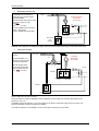
Circuit Tipology
2
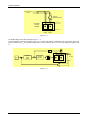
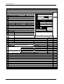
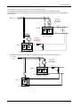
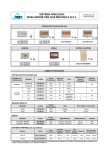
Regenerating connection only”
Vin = power
This application use a diode bridge for
motoring (RTD) and a thyristor bridge for
regenerating SPDMR.
supply
TR step-up transformer
Vs = Vf/1,05
Vf = Braking voltage
Define the operating voltage class according
the secondary voltage (Vs) of the
transformer.
(ex. G
Vs= 500 V)
-
The output +SPDMR must be connected to
terminal – of the RTD and
the output –SPDMR to the terminal +RTD
Fus.
L
+
D
–
+
+
SPDMR Thyristors bridge
(regenerating)
Diodes bridge
RTD
(motoring)
-
WARNING!: in this application the SPDM power supply must be insulated from RTD power supply ( a transformer must be used).
3
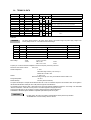
Twelve pulse connection
This application use a two
converters.
Vin=voltage
power supply
ATR step-up
autotransformer
TR
The converter SPDMR a) is a
sinle bridge converter (motoring)
in twelve pulse configuration.
Vs = 1,25Vin
Define the operating voltage
class according the secondary
voltage of the transformer TR.
(ex. G
Vs= 500 V)
Fus.
Reactor
L
b)SPDMR
+
D
–
Forward bridge
motoring
Reverse bridge
regenerating
+
a) SPDMR
–
Forward bridge motoring
Application 2-3: SPDMR are identical to SPDM (2 quadrant) [The only difference is the control bord (“COREA” instead of CONDB)].
Refers to SPDM manual for power connections.
With the same BUS DC voltage, the SPDMR two quadrant (application 2) must be suitable for an operating voltage greater than the
application 3 ( at list 1,25)
The SPDMR concerning the applications 2 and 3a are identical, the only difference is the internal voltage transducer connection. The
applications 3b SPDMR is identical to the application 1SPDMR.
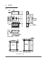
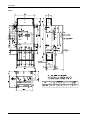
It is possible to parallel the converter SPDMR: The slave converter (without control board) is named RTTR
SPDMR
A2-3