1
LCD12864-COG
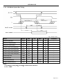
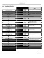
4.6 Basic Operating Sequence
4.6.1 Initialization Sequence
Turn on Power Supply VDD & VSS While
maintaining /RES at LOW
D1
D0
A0
D7
D6
D5
D4
D3
D2
Code Function
Note
hex
-
-
-
-
-
-
-
-
-
-
-
-
-
-
-
-
-
-
-
-
-
-
Release the /RES Reset Signal
(/RES = High)
-
-
-
-
-
-
-
-
-
-
See AC Characteristics section for timing
details
LCD Bias = 1/9
0
1
0
1
0
0
0
1
0
A2H
LCD Characteristics
ADC = Normal
0
1
0
1
0
0
0
0
0
A0H
No flip on x-direction (SEG)
SHL = Reverse
0
1
1
0
0
1
0
0
0
C8H
Flip on y- direction (COM)
Initial Display Line = 0
0
0
1
0
0
0
0
0
0
40H
i.e. Display RAM “Page 0-D0”
Matched to top line of the LCD
0
0
0
1
0
1
1
0
0
2CH
Turn on the internal Voltage Converter and
wait until VOUT stable
-
-
-
-
-
-
-
-
-
-
0
0
0
1
0
1
1
1
0
2EH
-
-
-
-
-
-
-
-
-
-
0
0
0
1
0
1
1
1
1
2FH
-
-
-
-
-
-
-
-
-
-
Regulator Resistor Select
0
0
0
1
0
0
1
0
1
25H
Set the built-in resistor ratio to middle
Set Reference Voltage Mode
Set Reference Voltage Resistor
0
0
1
0
0
0
0
1
0
0
0
0
0
0
0
0
1
0
81H
20H
Set to the middle of the range it may be adjused
For achieving the best display contrast
Display ON
0
1
0
1
0
1
1
1
1
AFH
Turn on the LCD display
Set Page Address = 0
0
1
0
1
1
0
0
0
0
B0H
Specify the display data RAM page address to
00H
Set Column Address (Upper -4bit = 0)
Set Column Address (Lower-4bit =4)
0
0
0
0
0
0
0
0
1
0
0
0
0
1
0
0
0
0
10H
04H
Specify the display data RAM column address
to 00H
Write Display Data
1
Wait until power supply is stabilized
Power Control
Voltage Follower = OFF
Voltage Regulator = OFF
Voltage Converter = ON
Delay 50ms
Power Control
Voltage Follower = OFF
Voltage Regulator = OFF
Voltage Converter = ON
Delay 50ms
Power Control
Voltage Follower = OFF
Voltage Regulator = OFF
Voltage Converter = ON
Delay 50ms
Display Data
Turn on the internal Voltage Regulator and
wait until VOUT stable
Turn on the internal Voltage Follower and
wait until VOUT stable
-
Write Other Display Data
Page 11 of 14