1
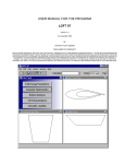
User Guide
SunTek’s Exclusive
PPF and Window Tint
Cutting Software
Table of Contents
Contact Information3
Copyright Notice4
Introduction to TruCutTM 5
Installing TruCutTM6
Part 1 - Program Installation
6
Part 2 - Plotter Installation
7-8
Part 3 - Launching TruCutTM9
Working With TruCutTM
10
Selecting Film Width10
Selecting Database & Vehicle
Year, Make, and Model
11-12
Nesting, Group Nesting & Cutting
13-14
Pattern Edit
15-16
Remove/Delete Sensor or Emblem
17-18
Outlining Pattern for Wrapping and
Adding Relief Cuts
19-20
Save Pattern21
Hot Key and Shortcuts22
Keyboard Shortcuts22
Function Keys22
2
TruCutTM User Guide
Technical Support
For technical support please contact the following:
Alan Agee 276.632.4991 ext. 430
Josh Rodgers 276.632.4991 ext. 428
Andrew Joyce 276.632.4991 ext. 431
Website Support:
www.suntektrucut.com
www.suntekfilms.com
www.commonwealthlaminating.com
3
TruCutTM User Guide
Copyright Notice
No part of this publication may be reproduced mechanically or
electronically or in any form without the prior written permission
of Commonwealth Laminating & Coating, Inc (CLC). The software
described in this manual is furnished under license and may only
be used or copied in accordance with the terms of such license.
The information in this manual is for informational use only, is
subject to change without notice and should not be construed as
a commitment of CLC. CLC assumes no responsibility or liability
for any errors or inaccuracies that may appear in this document.
TruCutTM and PPFTM are registered trademarks of Commonwealth
Laminating & Coating, Inc.
4
TruCutTM User Guide
Installing TruCut
TM
An orange USB security dongle is provided with TruCutTM to
prevent unauthorized use or pirating of software. This dongle is
a flash drive that plugs into a standard USB port of the computer
and is transparent to other applications. Only TruCutTM is aware of
the device.
Connect your orange dongle BEFORE installing your TruCut software!
TM
Policy On Lost Or Stolen Dongles
•
The USB dongle provided with TruCutTM is your proof of
purchase. If the dongle is lost or stolen, that is equivalent to
losing the entire software package, and a new package of
TruCutTM must be purchased.
•
In the event of a damaged dongle that must be replaced,
there is a nominal fee for EXCHANGING a new dongle for the
older dongle, where the older dongle must be reclaimed by
Commonwealth Laminating & Coating, Inc. (CLC).
5
TruCutTM User Guide
Part 1 - Program Installation
The following steps will walk you through the installation of
TruCutTM.
1. Insert the orange USB dongle into an open USB port on your
computer.
2. Insert the TruCutTM DVD into your DVD-ROM drive. The Install
Wizard should “start automatically”.
If the install wizard fails to start automatically, start the
installation process manually:
a) From the Start menu, choose Run to open the Run dialog box.
b)Click Browse and locate the setup.exe file that is on the DVD in the DVD-ROM drive.
c)Click Open to choose the setup.exe file.
d)Click OK to close the Run dialog.
3. Proceed with each stage of the Install Wizard. Instructions are
provided at each stage.
4. When the Install Wizard is complete, proceed to Part 2 Plotter Installation.
6
TruCutTM User Guide
Part 2 - Plotter Installation
Now that TruCutTM has been installed, you are ready to install your
plotter. The following steps are an overview of the plotter
installation process.
1. Left click on the “Cut” menu - refer to image 2.1
2. Left click “Plotting Defaults” - refer to image 2.1
3. In the “Select Driver Box” ensure that the correct plotter is selected refer to image 2.2
4. Left click the “Setup” button - refer to image 2.2
5. Left click the “Port” tab - refer to image 2.3
6. In the “Port Location” box, select the appropriate port location for
your plotter - refer to image 2.3
(If your plotter is a GCC the correct port will be at the bottom of
the list. “Unknown USB_USB0--”)
7. Left click the “Apply” then the “OK” buttons
8. In the “Cut” box, select “Sign Blank” only - refer to image 2.4
9. Left click the “Apply” then the “Close” buttons - refer to
image 2.5
10.TruCutTM is now ready to cut
Note: For technical assistance, refer to contact information on page 3.
7
TruCutTM User Guide
Part 2 - Plotter Installation (continued)
2.1 Plotting Defaults
2.2 Select Driver
2.4 Sign blank
2.3 Port Tab & Port Location
8
2.5 Apply & Close
TruCutTM User Guide
Launching TruCut
TM
The following steps are an overview of launching TruCutTM.
1. Click the TruCutTM icon on your desktop or select the TruCutTM
software icon in your program menu.
2. Allow TruCutTM program 10-15 seconds to launch
TruCutTM database will automatically update during the
launching process. This may occur on a weekly or monthly
basis depending on the software update schedule. (Contact
technical support regarding software update questions)
*Internet should always be connected
TruCut Launching Screen
TM
9
TruCutTM User Guide
Selecting Film Width
The following steps are an overview of selecting the film width in
TruCutTM.
1. Click the “Film Width” drop down menu (refer to image 3.1)
and select from the following options:
• 12 inch
• 18 inch
• 20 inch
• 24 inch
• 30 inch
• 36 inch
• 40 inch
• 48 inch
• 60 inch
3.1 Selecting Film Width
10
TruCutTM User Guide
Selecting Pattern Database and Vehicle:
Year, Make, and Model
The following steps are an overview of selecting the
desired Pattern Database and Vehicle: Year, Make, and Model in
TruCutTM.
1. First, choose your database type, either Window Tint or Paint
Protection - refer to image 3.2
2. Click the “Year” drop down menu and select from the list of
vehicle year options - refer to image 3.3
3. Click the “Make” drop down menu and select from the list of
vehicle make options - refer to image 3.4
3. Click the “Model” drop down menu and select from the list of vehicle model options - refer to image 3.5
If your desired vehicle year, make, or model is not an
option please contact technical support.
3.2 Select Database: Window Tint or Paint Protection
11
TruCutTM User Guide
Selecting Vehicle: Year, Make, and Model (continued)
Clicking “A
3.3 Select Vehicle Year
3.4 Select Vehicle Make
12
3.5 Select Vehicle Model
TruCutTM User Guide
Nesting, Group Nesting & Cutting
The following steps are an overview of cutting a specific
pattern in TruCutTM.
1. Hold down the left button on your mouse and draw a box
around your desired pattern - refer to image 4.1
2. Holding the “Shift Key” while holding the left button on your
mouse will allow you to select multiple patterns
3. Pattern will highlight in RED - refer to image 4.2
4. Click the “Nest” or “Group” button - refer to image 4.3
5. Click “Cut” to begin the cutting process on the plotter
4.1 Selecting the Pattern
4.2 Selected Pattern
(Highlighted in Red)
4.3 Nesting Selected Pattern
13
TruCutTM User Guide
Selecting a Specific Pattern, Nesting and Group
Nesting (continued)
The difference between Nest and Group
Nest: When selecting the “Nest” button, patterns will group as
close as possible, maximizing film efficiency and
minimizing waste. Refer to image 4.4
Group: When selecting the “Group” button, patterns will group in
the same layout seen in the pattern view (necessary for window
tint patterns, due to orientation required for heat shrinking), keeping the same format. Refer to image 4.5
4.4 Clicking the “Nest” button
4.5 Clicking the “Group” button
14
TruCutTM User Guide
Pattern Edit
The following steps are an overview of applying a pattern edit in
TruCutTM.
1. Click the pattern to edit. (pattern will turn RED)
A duplicate of the selected pattern should be created before
editing. To make a duplicate, select the pattern and press the
Ctrl + D keys on your keyboard or click the
Duplicate Icon. This places a duplicate directly on top of the existing
pattern.
To see the changes that will take place between the two
patterns, you will need to turn the fill color off. To do this, press
the Alt + S keys on your keyboard.
2. With the pattern duplicated and selected, push the letter “E” on
your keyboard. (blue nodes will appear on selected pattern) refer to image 5.1
3. Holding down the “Shift” key, draw a box using your mouse
around the nodes you would like to edit. (nodes will turn RED
when selected) - refer to image 5.2
4. Using the arrow keys on your keyboard, move the points in the
direction of your desired edit - refer to image
5.3 & 5.4
Each press of the arrow key will move the selected nodes 1/16
of an inch.
5. Delete nodes from a pattern by selecting the nodes and
clicking “Delete” on your keyboard - refer to page #19
6. Click “Apply” at the top of your screen to save the edited
patterns.
Clicking “Apply” will only save the pattern until the software is
closed. To save the pattern edit for later use, select the “Save
As” function and save to your desktop folder.
15
TruCutTM User Guide
Pattern Edit (continued)
Clicking “A
5.1 Push “E” on your keyboard to edit pattern
5.2 Use “Shift” on keyboard to select pattern points
5.3 Before Edit
16
5.4 After Edit
TruCutTM User Guide
Remove/Delete Sensors or
Emblem From Pattern
The following steps are an overview of removing unwanted/
unnecessary cut-outs from a pattern (i.e. emblems and
sensors).
1. Click the pattern to edit. (pattern will turn RED)
2. With the pattern selected, push the letter “E” on your keyboard
or click the
“Edit Path” icon. (blue nodes will appear on
selected pattern)
3. Holding down the “Shift” key, draw a box using your mouse
around the nodes you would like to edit. (nodes will turn RED
when selected) - refer to image 6.1
4. Once all cut-outs are selected for deletion, press the delete
key on your keyboard - refer to image 6.2
5. Click “Apply” to save the edited pattern - refer to image 6.3
Click the following links to view a video demonstrating the
above steps in action:
- Video A: Pattern Edit
- Video B: Remove or Delete Sensors
17
TruCutTM User Guide
Remove/Delete Sensors or
Emblem From Pattern (continued) Clicking “A
6.1 Select area to delete
6.2 Push the “Delete” button on your keyboard
6.3 Click “Apply” to save pattern edit
18
TruCutTM User Guide
Outlining Pattern for Wrapping and Adding
Relief Cuts
1. While holding the Ctrl Key, Double Click the desired pattern
to unlock.
2. While holding the Shift and Alt keys, Left click and Hold
while dragging the mouse. This will create a duplicate of the
selected pattern that can be placed anywhere on the screen.
Once the pattern is located on the screen where you wish the
duplicate to be placed release all the buttons at once to create
the duplicate.
3. If the pattern has holes that need to remain their current size
follow this procedure, otherwise skip to step 4.
a). With the pattern selected click on the
Break Path Icon.
4. Select only the portion to be outlined and click the
Duplicate Icon.
5. Turn off the Show Fill by clicking the
6. With pattern selected click on the
Show Fill Icon.
Outline Icon.
7. In the Outline toolbar ensure that Outline is selected and
Inline is deselected. In the Outline Thickness box enter the
desired amount you wish to add to your pattern. Press enter
then click the Close Button on the Outline Toolbar.
- refer to image 7.1 & 7.2
7.1 Outline is selected
19
7.2 Close Button
TruCutTM User Guide
Outlining Pattern for Wrapping and Adding
Relief Cuts (continued)
8. To add Relief cuts in the corners the path will need to be
edited. With the pattern selected click on the
Edit Path
Icon.
9. Using the zoom tool zoom into a corner that will require a relief
cut.
10.Select nodes in the corner and delete so that the corner is
flattened off but does not cross over into the original pattern.
Now double click on the straight line to add a point. You can
now drag this point close to the original patterns corner without
crossing over. Your relief cut for that corner is done. Zoom to
each corner that needs a relief cut and repeat this step. Once
all relief cuts are made click the Apply Button on the Edit
Path Toolbar.
11.Select the original pattern and press the Delete Key on the
keyboard or the Clear Icon.
12.Select the edited pattern and any holes that were saved and
click on the Make Path Icon.
13.Turn the Show Fill back on by clicking the
Show Fill Icon.
Click the following link to view a video demonstrating the
above steps in action:
- Video C: Outlining a pattern
20
TruCutTM User Guide
Save Edited Pattern
The following steps are an overview of saving the edited pattern
from TruCutTM.
1. Click “File” on the top left navigation bar and select “Save As”
2. Name the file (your file name preference)
3. Select a folder destination to save the pattern file (default will
be My Documents folder)
4. Click “Save”
Easily access saved pattern for similar paint protection vehicle
cuts. Simply open saved pattern and cut.
Click “File” to access “Save As” option
Save pattern using “Save As” option
21
TruCutTM User Guide
TruCut Shortcut Keys
TM
The following shortcut Keys allow quick and easy software function.
KEYFUNCTION
Z
Zoom To Selected
P
Pan State
Ctrl + A
Select All
Ctrl + Double Click
Ctrl + D
Duplicate
Ctrl + F
Make Custom Film Width
Alt + S
Unlocks Selected Pattern
E
Toggles Show Fill
Edit Path
Space Bar
Backs out of current
command
Keyboard Arrows
22
Move Path Points When Selected
TruCutTM User Guide
www.suntekfilms.com
© 2013
Commonwealth Laminating & Coating, Inc.
Made in the USA