1
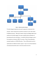
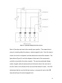
Figure 2 - Monitoring Block Diagram
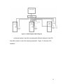
This block diagram breaks down how each component is connected to the
computer. Each of these devices would be connected to a door that needed
the additional security. Although the camera, keypad, and badge reader are all
mentioned in this block diagram, the user can specify which combination of
these devices the door should have. As outlined in the block diagram, each of
the connections is through a USB 2.0 connector. Each of the peripherals is
connected together at a USB HUB location. Then a USB extender would be
used between the USB hub and the computer. Figure 3 is a further breakdown
of the devices that will be used to control the access to the door.
13