1
Version number
1.0
1
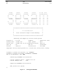
INTRODUCTION
1.1
PLATEWORK - Purpose
Date
01-JUN-1991
Page
1-1
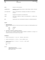
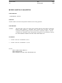
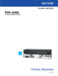
PLATEWORK is an interactive computer program with the main purpose of code checking stiffened plate
structures against rules and regulations issued by the following authorities:
•
API - American Petroleum Institute
•
DnV - Det norske Veritas
•
NPD - Norwegian Petroleum Directorate
The code check features are mainly buckling checks, with some yield check facilities, see PLATEWORK
Theoretical Manual /1/. PLATEWORK is based on the Capacity Model concept, and the following Capacity
Model types are included:
•
Simple, unstiffened plate (API, DnV, NPD)
•
Stiffener (API, DnV, NPD)
•
Girder (API, DnV, NPD)
•
Uniaxially stiffened panel (API)
•
Orthogonally stiffened panel (API)
The program has features for manual input of code check data, and extensive automatic features for extraction
of such data from Finite Element (FE) analyses. This allows PLATEWORK to be used in a stand-alone mode
or as a postprocessor to a FE-analysis.
Included are several features for graphics interaction and presentation. The code check results can be presented
as print/plot to a file or to the screen. The result print utilities include very flexible and user-controllable options for results sorting and filtering. This enables the user to tailor the program output for easy inclusion of
code-check results in an analysis report.
Page
1-2
Date
01-JUN-1991
Version number
1.0
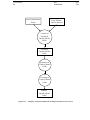
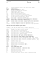
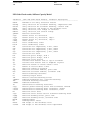
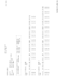
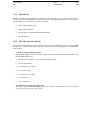
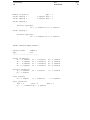
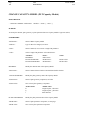
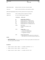
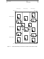
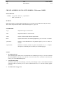
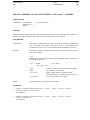
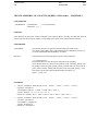
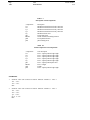
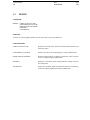
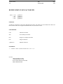
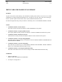
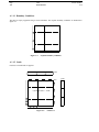
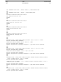
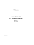
PLATEWORK is part of the SESAM suite of programs and operates on a local database file. When using the
program as a postprocessor to a FE-analysis, it also reads FE-results from the SESAM Interface File /3/. The
SESAM Interface File may have been created by the SESAM analysis program SESTRA /8/, the SESAM utility program PREPOST /4/ or by any other program.
1.2
PLATEWORK in the SESAM system
INTERACTIVE
PREPROCESSORS
ENVIRONMENTAL
LOADS
LAUNCH
launching,
floating and
upending of
jackets
PREFEM
general
structures
PREFRAME
frame
structures
PRETUBE
tubular
joints
PRESEL
superelement
assembly
I
N
P
U
T
I
N
T
E
R
F
A
C
E
F
I
L
E
WAJAC
wave loads
on frame
structures
SESTRA
static and
optional:
dynamic lin. nonlin. material,
structural
contact problem,
analysis
fract. mechanics
FENRIS
static and
dynamic
nonlinear
struct. anal.
STRUCTURAL
ANALYSIS
Figure 1-1
R
E
S
P.
I
N
T
E
R.
F
I
L
E
LOADS INTERFACE FILE
SPLICE
nonlinear
structurepile-soil
interaction
CAD/CAE
systems
WADAM
wave loads
on volumes
and slender
structures
G
L
O
B
A
L
R
E
S
U
L
T
S
I
N
T
E
R
F
A
C
E
F
I
L
E
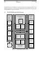
PLATEWORK in the SESAM system
INTERACTIVE
POSTPROCESSORS
POSTRESP
presentation
of statistical
response
CONCODE
concrete
design
PLATEWORK
plate
design
POSTFRAME
frame
design
POSTFEM
graphical
presentation
of results
POSTSIF
linear
fracture
mechanics
Version number
1.0
1.3
Date
01-JUN-1991
Page
1-3
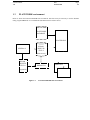
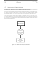
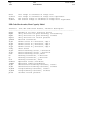
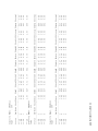
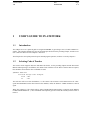
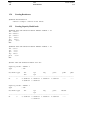
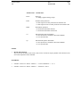
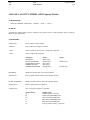
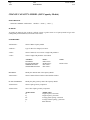
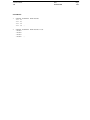
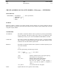
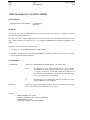
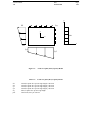
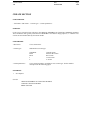
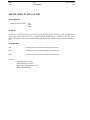
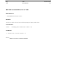
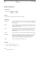
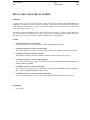
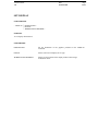
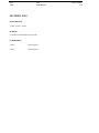
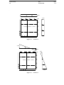
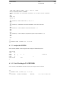
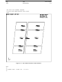
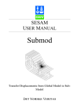
PLATEWORK environment
Below is shown the local PLATEWORK file environment. Note that it may be necessary to use the SESAM
utility program PREPOST /4/ to establish the SESAM results file in direct access
PLATEWORK
DATABASE
PLATEWORK
SESAM
RESULTS
FILE /3/
SESTRA /8/
(direct access)
SESAM
RESULTS
FILE /3/
PREPOST /4/
PRINT FILE
PLOT FILE
(sequential)
Figure 1-2
Local PLATEWORK file environment
Page
1-4
1.4
Date
01-JUN-1991
Version number
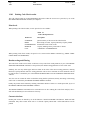
1.0
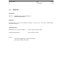
How to read this manual
Chapter 2 contains descriptions of important concepts employed in the program. A novice user should read this
chapter first.
Chapter 3 is a quick user’s guide and contains small concrete examples on how to use the concepts explained in
chapter 2.
Chapter 4 contains practical information on how to start the program, important files and program requirements
and limitations.
Chapter 5 provides a description of all program commands and associated input data.
Appendix A contains complete tutorial examples.
PLATEWORK Theoretical Manual
The basic theory behind the code checks are described in a separate manual, the PLATEWORK Theoretical
Manual /1/. This manual is an important reference document for any PLATEWORK user. References to API,
DnV and NPD code documents will be found here.
PLATEWORK Status List
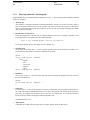
The latest information about minor program modifications, error corrections or amendments to the PLATEWORK documentation is available in the PLATEWORK Status List. The Status List will also state the latest
revision numbers of the PLATEWORK documentation.
This document is issued regularly by Veritas SESAM Systems A.S to every PLATEWORK installation. The
local SESAM installation responsible will be able to provide the latest copy.
PLATEWORK Maintenance Manual
The internal implementation aspects, programming tools and internal datastructures are described in a separate
manual, the PLATEWORK Maintenance Manual /2/. The manual is not generally available for PLATEWORK
users, but used by PLATEWORK maintenance responsible personnell.
Version number
1.0
Date
01-JUN-1991
1
FEATURES OF PLATEWORK
1.1
Introduction
Page
1-1
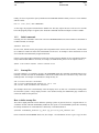
This chapter contains a broad description of important concepts employed and features available in PLATEWORK. It serves as a first introduction to the program principles for the novice user, and as a reference document for the more experienced user.
1.2
The Code Checks
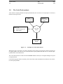
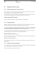
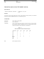
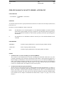
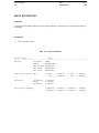
The main purpose of PLATEWORK is, as mentioned briefly in the preceding chapter, to perform code checks
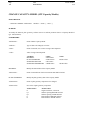
on stiffened plate structures. The current version supports the following checks, see also the Theoretical Manual /1/:
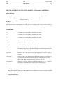
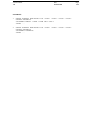
Table 1.1
Code checks
Type of checks
API
Plate yield and buckling checks
Stiffener yield and buckling checks
Girder yield and buckling checks
Uniaxially stiffened panel buckling checks
Orthogonally stiffened panel buckling checks
Code of Practice
DnV
NPD
X
X
X
X
X
X
X
X
X
X
X
The table shown above identifies certain structural parts that have been addressed by the different design codes.
These structural parts are in PLATEWORK called "Basic Capacity Models" or simply "Capacity Models", and
they are treated as separate entities independent of for example the elements in a Finite Element mesh.
The Basic Capacity Models are described in the following section.
Page
1-2
Date
01-JUN-1991
1.3
Version number
1.0
The Basic Capacity Model
In order to handle code checks in a simple, efficient and versatile way, a new entity called a Capacity Model is
introduced. Some important aspects characterizing the Capacity Model are:
1
Capacity Model types
There are 5 Capacity Model types :
a
Plate Capacity Models, denoted PLT.
b
Stiffener Capacity Models, denoted STF.
c
Girder Capacity Models, denoted GIR.
d
Uniaxially Stiffened Panel Capacity Models, denoted USP.
e
Orthogonally Stiffened Panel Capacity Models, denoted OSP.
2
Capacity Models are separate, named objects
The Capacity Models are stored as separate objects in the PLATEWORK database, no code checks can be
performed without the explicit creation of Capacity Models. Each Capacity Model is identified by a
unique name.
3
Capacity Models are origin-independent
The Capacity Model objects are to a large extent independent of the way in which they were created. This
makes it possible to create Capacity Models either "manually" (i.e. by entering all data directly via the
PLATEWORK commands), or "automatically" by reference to a Finite Element Model (i.e. most of the
Capacity Model input data is inferred from analysis of the Finite Element Model geometry). The Code
Check module does not distinguish between two Capacity Models that were created in one or the other
way.
4
Capacity Models may be assigned to specific locations within a larger structure
A structure may for example have several plates with identical dimensions, plate thicknesses, material etc.
These plates will be defined as separate Capacity Models, because the stresses in the plates (which form
the basis for calculation of Capacity Model loads) will be different in the general case.
Version number
1.0
1.3.1
Date
01-JUN-1991
Page
1-3
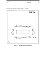
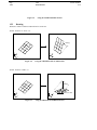
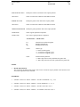
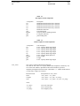
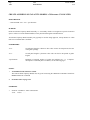
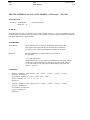
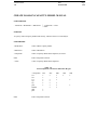
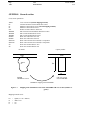
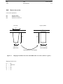
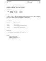
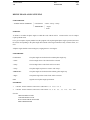
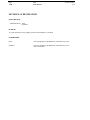
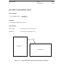
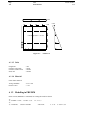
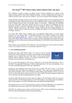
The plate Capacity Model (PLT)
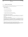
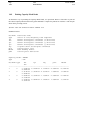
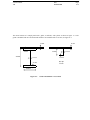
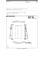
The plate is the geometrically simplest of the Capacity Models in PLATEWORK. It is used for checking individual plates between stiffeners and girders within a stiffened panel. Its geometry is described by the following
paramers:
lx
ly
t
Length of plate, x direction
Length of plate, y direction
Plate thickness
For a complete description of all plate Capacity Model parameters, see the Theoretical Manual.
ly
-t-
y
lx
x
Figure 1-1
The plate Capacity Model
Page
1-4
Date
01-JUN-1991
1.3.2
Version number
1.0
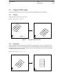
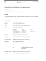
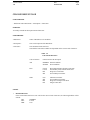
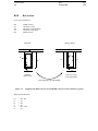
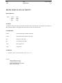
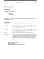
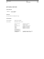
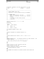
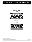
The stiffener Capacity Model (STF)
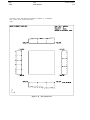
The stiffener Capacity Model is used for checking individual stiffeners within a stiffened panel. Its main geometry is described by the following parameters:
lx
ly1
ly2
t1
t2
length of stiffener, x direction
Stiffener spacing BEFORE stiffener
Stiffener spacing AFTER stiffener
Plate thickness BEFORE stiffener
Plate thickness AFTER stiffener
In addition to the main geometry parameters, the stiffener is also described by the stiffener section parameters
hws
tws
bfs
tfs
afs
efs
Stiffener web height
Stiffener web thickness
Stiffener flange width
Stiffener flange thickness
Distance between webs (=0.0 if one web)
Flange eccentricity
For a complete description of all stiffener Capacity Model parameters, see the Theoretical Manual.
2
2
- t2 -
1
2
- t1 -
ly
ly
stiffener
y
lx
x
Figure 1-2
The stiffener Capacity Model
Version number
1.0
1.3.3
Date
01-JUN-1991
Page
1-5
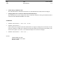
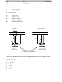
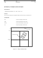
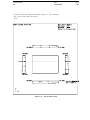
The girder Capacity Model (GIR)
The girder Capacity Model is used for checking individual girders within a stiffened panel. Its main geometry
is described by the following parameters:
Ly
lx1
lx2
t1
t2
lya
Length of girder, y direction
Girder spacing BEFORE girder
Girder spacing AFTER girder
Plate thickness BEFORE girder
Plate thickness AFTER girder
Average stiffener spacing, y direction
girder
Ly
- t1 -
stiffener
- t2 -
lya
y
x
2
2
1
2
lx
lx
Figure 1-3
The girder Capacity Model
In addition to the main geometry parameters, the girder is also described by the girder and stiffener section
parameters:
Girder section
hwg
Girder web height
twg
Girder web thickness
bfg
Girder flange width
tfg
Girder flange thickness
afg
Distance between webs (=0.0 if one web)
efg
Flange eccentricity
Page
1-6
Date
01-JUN-1991
Version number
1.0
Stiffener section
hws
Stiffener web height
tws
Stiffener web thickness
bfs
Stiffener flange width
tfs
Stiffener flange thickness
afs
Distance between webs (=0.0 if one web)
efs
Flange eccentricity
For a complete description of all girder Capacity Model parameters, see the Theoretical Manual.
Version number
1.0
1.3.4
Date
01-JUN-1991
Page
1-7
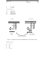
The uniaxially stiffened panel Capacity Model (USP)
The uniaxially Capacity Model is used for checking the entire uniaxially stiffened panel in an API Code Check.
Its main geometry is described by the following parameters:
Lx
Ly
lya
t
Length of panel, x direction
Length of panel, y direction
Average stiffener spacing, y direction
Plate thickness
In addition to the main geometry parameters, the uniaxially stiffened panel is also described by the stiffener
section parameters
hws
tws
bfs
tfs
Stiffener web height
Stiffener web thickness
Stiffener flange width
Stiffener flange thickness
For a complete description of all uniaxially stiffened panel Capacity Model parameters, see the Theoretical
Manual.
stiffener
-t-
Ly
y
Lx
x
Figure 1-4
The uniaxially stiffened panel Capacity Model
lya
Page
1-8
Date
01-JUN-1991
1.3.5
Version number
1.0
The orthogonally stiffened panel Capacity Model (OSP)
The orthogonally stiffened panel Capacity Model is used for checking the entire orthogonally stiffened panel in
an API Code Check. Its main geometry is described by the following parameters:
Lx
Ly
lxa
lya
t
Length of panel, x direction
Length of panel, y direction
Average girder spacing, x direction
Average stiffener spacing, y direction
Plate thickness
girder
Ly
stiffener
-t -
lya
y
x
Lx
lxa
Figure 1-5
The orthogonally stiffened panel Capacity Model
In addition to the main geometry parameters, the orthogonally stiffened panel is also described by the girder
and stiffener section parameters:
Girder section
hwg
Girder web height
twg
Girder web thickness
bfg
Girder flange width
tfg
Girder flange thickness
Stiffener section
hws
Stiffener web height
tws
Stiffener web thickness
bfs
Stiffener flange width
tfs
Stiffener flange thickness
For a complete description of all orthogonally stiffened panel parameters, see the Theoretical Manual.
Version number
1.0
1.4
Date
01-JUN-1991
Page
1-9
The Capacity Model Assembly
The Capacity Models described in the previous section are basic entities that represent only small parts of a
total structure. In order to code check a complete structure, many Capacity Models will have to be defined.
If the Capacity Models were to be created one by one, in separate operations, it would require extensive user
input. One would also ignore the fact that Capacity Models within a certain area usually have a lot in common,
for example:
•
Common material
•
Common plate thickness between adjacent stiffener and plate Capacity Models
•
Girder spacings define stiffener lengths and vice versa.
•
Stiffener cross sections are the same in adjacent stiffener and girder Capacity Models
•
etc.
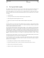
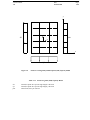
In realizing the above, the concept of the Capacity Model Assemby is introduced. A Capacity Model Assembly
represents not just a simple plate, stiffener or girder, but a complete stiffened panel with Basic Capacity Models that are logically and geometrically connected.
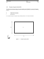
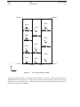
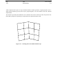
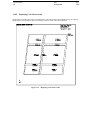
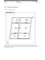
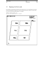
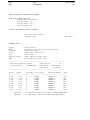
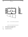
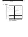
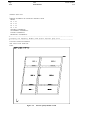
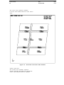
The stiffened panel defined through a Capacity Model Assembly is a flat, rectangular area with main girders
running parallel to two of the sides in the rectangle. The stiffeners run in the direction defined by the two remaining sides in the rectangle (i.e. at right angles wrt. the girders). The plates occupy the areas between the
stiffeners and girders. The API-specific Capacity Models (Uniaxially & Orthogonally Stiffened Panels) occupy
the whole Capacity Model Assembly area, but their geometry descriptions are simpler than the general description of the Capacity Model Assembly. For an example of a Capacity Model Assembly, see figure 1-6, page
1-10..
Note that the girder Capacity Models cover the whole span of the Capacity Model Assembly, while the stiffener Capacity Models only cover the area between two adjacent girders.
Note also the definition of the local coordinate system within a Capacity Model Assembly. This local coodinate
system is shared by all Basic Capacity Models within the Assembly, except when the assembly area shape is
distorted (not 100% rectangular):
•
The Assembly area is defined by four corners, numbered as shown on figure 1-6..
•
The local x-axis goes from corner 1 to corner 2. The local y-axis goes from corner 1 to corner 4.
•
Girders are always oriented in the local y-direction.
•
Stiffeners are always oriented in the local x-direction.
Page
1-10
Date
01-JUN-1991
Version number
1.0
Corner 4
Corner 3
-Plate-
-Plate-
y
y
-Plate-
x
y
Stiffener
x
Stiffener
x
-Plate-
Stiffener
y
-Plate-
x
Stiffener
y
x
-Plate-Plate-
Stiffener
y
y
x
x
Stiffener
Stiffener
-Plate-
-Plate-
-Plate-
y
x
y
Corner 1
y
y
x
x
Girder
Girder
Corner 2
x
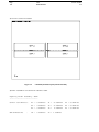
Figure 1-6
The Capacity Model Assembly
The Capacity Model Assembly is, as the Basic Capacity Models are, stored as a separate object in the PLATEWORK database. Its main purpose is to organize the description of the stiffened panel, such that Basic Capacity Models can be created efficiently, i.e. it should be seen as a means of organizing input data to the process
that creates the Basic Capacity Models.
Version number
1.0
1.4.1
Date
01-JUN-1991
Page
1-11
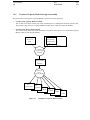
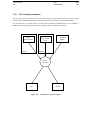
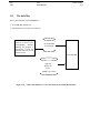
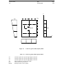
Creation of Capacity Models through an Assembly
The process that creates the Basic Capacity Models, is split into two main operations:
1
Creation of the Capacity Model Assembly
This is done on the basis of direct user input, optionally also by reading Finite Element geometry data.
The product of this process is a Capacity Model Assembly object, which is stored in the database.
2
Creation of the Basic Capacity Models
This is done solely on the basis of the Assembly. The products of this process are several Basic Capacity
Models, which are stored in the database.
Finite Element
Direct User
Input
Geometry data
Optional
Creation of
Capacity Model
Assembly
Capacity Model
Assembly
Creation of
Basic
Capacity Models
Basic
Capacity Model Basic
Capacity Model Basic
Basic
Capacity Model
Basic
Capacity Model
Capacity ModelBasic
Capacity Model
Figure 1-7
Principles of Capacity Model creation
Page
1-12
1.4.2
Date
01-JUN-1991
Version number
1.0
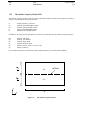
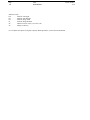
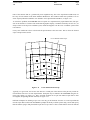
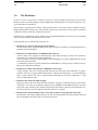
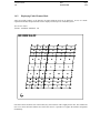
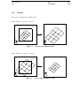
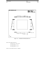
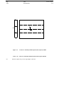
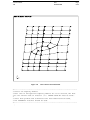
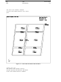
Creation of Capacity Model Assemblies through a Finite Element mesh
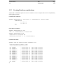
The figure below shows part of a Finite Element Model that represent a stiffened panel as described earlier.
PLATEWORK contains features for locating the Capacity Model Assembly (by means of the 4 corners) by
referencing nodes in the FE-model (for example by pointing in the mesh display).
If, for example the girders and stiffeners have been modelled with beam elements and the plates have been
modelled with shell or membrane elements, the user can then instruct PLATEWORK to automatically identify
the girders, stiffeners, plate thicknesses, materials, cross sections etc., that together constitute a complete Capacity Model Assembly description, independent of the Finite Element mesh refinement. In the figure below,
this would lead to an assembly with one girder, two stiffeners and four plates.
The Basic Capacity Models are created solely on the basis of the Assembly, as described in the previous section. From this it follows that Capacity Models can be efficiently created on the basis of a FE-model.
Corner 4
Corner 3
Finite Element
mesh
Stiffer beams
Corner 1
Corner 2
Girder beams
Figure 1-8
Creating Capacity Models through a FE-model
Version number
1.0
1.4.3
Date
01-JUN-1991
Page
1-13
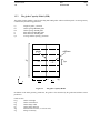
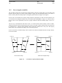
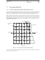
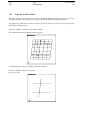
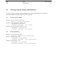
Non-rectangular assemblies
The preceding sections have described the normal situation, where the general shape of the assembly (and
therefore also the shape of the basic Capacity Models) comply with the assumptions made by the Codes of
Practice, namely that the assembly shape is rectangular (parallel sides & 90 degree corner angles).
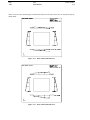
In some cases, real structures do not fully comply with these requirements. To allow for such structures to be
code checked, non-rectangular assemblies may be modelled in PLATEWORK, see figure 1-9. It must be noted,
however, that it is the responsibility of the user to judge whether the distorted assembly shape is not too extreme.
The best way to understand how this feature works, is to assume that the whole assembly is made of rubber,
and then stretched to fit the area described by the 4 corners. From this it follows that the local axis systems will
be stretched also, i.e. adjacent Capacity Models will no longer have parallel local x- and y-axes. The Capacity
Model loads will be calculated according to the real structure geometry.
In the Code Checks, an idealised shape will be assumed. The Theoretical Manual descibes the shape idealisations in more detail.
Corner 4
Corner 3
y
Corner 4
Corner 3
y
x
x
y
y
x
Corner 1
x
Corner 2
Real structure shape
Figure 1-9
Corner 1
Corner 2
Idealized rectangular shape
A "stretched" Capacity Model Assembly
Page
1-14
1.5
Date
01-JUN-1991
Version number
1.0
The element Scope
The scope facility is used to limit the part of the FE-model that can be accessed, in order to
•
Reduce CPU-time used and increase program response
•
Improve overview of the model, for example in the mesh display
•
Guide the program in finding correct solutions, for example when creating Capacity Models on the basis of
the element mesh, as described in section 1.4.2.
1.5.1
Superelement analyses and the element Scope
The superelement technique is an inherent feature of most SESAM programs. This technique is extremely efficient during the pre-processing phase, when repeated identical parts of the whole structure only have to be
modelled once. This feature is also very important in the analysis phase, since each superelement stiffness matrix only has to be computed once, and then re-used several times. The multi-level superelement technique thus
provides the user with a tool able to solve problems of almost unlimited size.
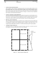
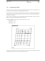
On the post-processing side, however, the situation is slightly less favourable. Repeated superelements have
typically the same geometric properties, but they invariably have different loads and results, making it necessary to post-process each superelement repetition individually. Also, the convenient subdivision into superelements may turn out to be an obstacle on the post-processing side.
A Capacity Model Assembly
which crosses a superelement
boundary.
Superelement A
Figure 1-10
Superelement B
Capacity Model Assembly crossing superelement boundaries
Version number
1.0
Date
01-JUN-1991
Page
1-15
Parts of the structure that are geometrically close neighbours may, due to the superelement subdivision, not
have any obvious relation in the Finite Element datastructure. This situation could cause problems if for instance Capacity Models Assemblies were defined to cross superelement boundaries, see figure 1-10.
To solve these problems, PLATEWORK does not operate on a superelement by superelement basis, but operates on the structure as a whole. This means that all graphics display, coordinates entered by the user etc., are
always relative to the top level coordinate sytem, which also happens to be the "true" coordinate system of the
real structure.
It may seem inefficient to have to deal with all superelements at the same time. That is where the element
scope concept becomes useful.
A User-defined element scope
Superelement A
Figure 1-11
Superelement B
A user-defined element scope
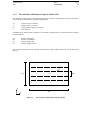
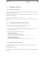
Typically, at a given time, one focuses ones interest to a small part of the structure. This part may contain Finite Elements from one or several superelements. Such parts may be defined in PLATEWORK using the element scope facility, see figure 1-11. Here, specified elements can be put into named scopes that are later
investigated, disregarding all other elements, see figure 1-12.
Different techniques for defining scopes exist. One may put all elements from one or several superelements
into the scope. More useful in PLATEWORK is perhaps the facility to define a plane using 3 nodes and specify
that all elements lying in that plane shall be put into a scope. There is also a similar feature where all elements
Page
1-16
Date
01-JUN-1991
Version number
1.0
within a trapezoid can be put in a scope. Elements that have common geometric or logical properties (for example common element type) may in this way be grouped together, even if the elements come from different
superelements.
The element scope facility thus enables the user to limit his current area of interest, but does not pose the limitations that a postprocessor operating on a superelement by superelement basis would.
Figure 1-12
Working with a user-defined element scope
Version number
1.0
1.6
Date
01-JUN-1991
Page
1-17
The Resultcase
In order to execute a Code Check, one must not only have Capacity Models but also loads on the Capacity
Models. In order to efficiently organize Capacity Model loads (and subsequently Code Check results), the concept of a Resultcase is introduced.
The Resultcase is typically used to identify Capacity Model loads (or code check results) of different Capacity
Models that physically belong to the same external structural load. Resultcases are also used to control the
combination of basic results into combination resultcases.
Resultcases are represented as separate entities in the PLATEWORK database, and also used for controlling
access to Capacity Model loads and Code Check results.
Some important aspects characterizing resultcases are:
•
Resultcases are separate, named objects in the database
No code checks can be performed without either explicit creation of resultcases, or through inheritance of
resultcases from an FE-analysis.
•
Resultcases are either BASIC or COMBINATION resultcases
A basic resultcase may typically be inherited from a Finite Element Analysis, in which case FE-stresses
exist and may be converted into Capacity Model loads.
A basic resultcase can also be created manually in PLATEWORK. The Capacity Model loads must in this
case also be defined manually.
A combination resultcase is typically defined in PLATEWORK, by referring to basic resultcases and applying factors and phase shift angles.
•
Resultcases are either of the STATIC, COMPLEX or SCAN types
A static resultcase will refer to Capacity Model loads that have only static load components. A complex
resultcase will refer to Capacity Model loads that have complex load components, i.e. real and imaginary
terms. A scan resultcase will refer to Capacity Model loads that have scan load components, i.e. both
static, real and imaginary terms.
•
Resultcases have limit-state kinds assigned
During execution of the code checks, different limit-states will apply for different loads, due to the nature
of the load, or the safety level required (examples are the NORMAL and STORM conditions in the API
code checks). The resultcases have therefore assigned limit-state kinds, so that the relevant limit-state factors can be fetched as the loads within the different resultcases are checked.
•
Resultcases & Capacity Models provide a convenient system for referencing loads and results
The Resultcase and Capacity Model names are the main keys through which the Capacity Model loads and
the corresponding code check results are referenced by the user.
Page
1-18
Date
01-JUN-1991
1.6.1
Version number
1.0
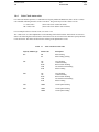
Combination resultcases & combination formulae
As mentioned above, resultcases can be either basic or combinations of basic resultcases. Combination resultcases are defined using the following procedure:
1
Create the basic resultcases
This is done either by reading in a SESAM Results Interface File (direct access format, the so-called SINfile) in which case basic resultcases will be automatically inherited from the FE-analysis. Alternatively,
basic resultcases can also be created manually in PLATEWORK by use of the CREATE RESULTCASE
command (BASIC option).
2
Create the combination resultcases
Once the basic resultcases have been created, the CREATE RESULTCASE command (COMBINATION
option) should be used to define the combination resultcases. In addition to simple descriptive data, the
following information will be required:
a
Destination resultcase kind
The combination must be specified as either STATIC, COMPLEX or SCAN, independent of the basic
resultcases input to the combination.
b
Source resultcase names
Names of the source resultcases (i.e. basic or previously defined combination resultcases) must be entered.
c
Source resultcase factor
A scale factor (F in table 1.2) for each source resultcase must be entered.
d
Source resultcase phase shift angle.
A phase shift angle (θ in table 1.2) must be entered for each source resultcase.
Table 1.2
Result combination formulae
Source kind
STATIC
COMPLEX
STATIC
COMPLEX
STATIC
COMPLEX
[S]
[R,I]
[S]
[R,I]
[S]
[R,I]
Combination formula
Destination kind
F*[ Scosθ ]
F*[ Rcosθ-Isinθ ]
F*[ Scosθ, Ssinθ ]
F*[ Rcosθ-Isinθ, Icosθ+Rsinθ ]
F*[ Scosθ ]
F*[ Rcosθ-Isinθ, Icosθ+Rsinθ ]
STATIC
STATIC
COMPLEX
COMPLEX
SCAN (STATIC part)
SCAN (COMPLEX part)
[S]
[S]
[R,I]
[R,I]
[S,R,I]
[S,R,I]
Combination is performed on unreduced Capacity Model loads
Note that the combination is performed on the basis of the unreduced Capacity Model loads (see section 1.7,
The Capacity Model Load), i.e. NOT when the CREATE RESULTCASE command is entered, but when the
CREATE LOAD-ON-CAPACITY-MODEL AUTOMATIC command is entered.
Version number
1.0
Date
01-JUN-1991
Page
1-19
1.7
The Capacity Model Load
1.7.1
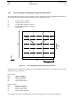
Creation of Capacity Model loads from Finite Element stresses
After creating a Finite Element Model, and running the analysis, stress and force results exist on the SESAM
Interface File as shown schematically in the figure below. After creating the Capacity Models as described in
section 1.4.2, the Finite Element stresses must be converted and processed to form Capacity Model loads.
What is logically one Capacity Model (e.g. the upper right quarter of the figure, which forms a plate Capacity
Model) may consist of several finite elements (in this case 3x3=9 elements). The stress functions along the
CM boundaries are typically piecewise non-continous linear functions. The Capacity Models require constant
or linear load functions along their boundaries, see Theoretical Manual. The stress functions must therefore be
simplified before they can be used.
Load Transformation points
Finite Element
mesh
Plate stresses
Stiffer beams
Beam force
Girder beams
Figure 1-13
Stresses and forces from a Finite Element Analysis
In order to transform the rather complicated stress functions into simple, linear load functions, the following
procedure is used (see also figure 1-15):
Page
1-20
Date
01-JUN-1991
Version number
1.0
1
Creation of load transformation points
After creating the Capacity Models (by indicating the location of the Capacity Model Assembly wrt. the
Finite Element Model), the so-called "load transformation points" can be found for each edge of all Capacity Models. There will be 2 times as many points per CM edge as there are Finite Elemens along that
edge, in order to properly represent the piecewise non-continous stress function. Each load transformation
point contains information about which Finite Element it "belongs" to, and the necessary extrapolation
and coordinate system transformation information.
2
Creation of "unreduced" Capacity Model loads
After all the load transformation points have been established, the program uses them during the processing of stresses. The stresses are estimated in each point for all resultcases and Capacity Models. The result
of this process is called "unreduced" Capacity Model loads, because of the arbitrary shape of the function.
The unreduced Capacity Model loads are stored in the database, and may be displayed graphically.
3
Reduction of Capacity Model loads
After establishing the unreduced loads, the penultimate step in estimating the final Capacity Model loads
consists of a simple integration (trapezoid method), where the total edge force and in-plane edge moment
are established. By assuming a linear distribution along the CM edges of these total forces, the unaveraged Capacity Model loads are obtained (i.e. one linear function per edge of the Capacity Model).
4
Averaging of Capacity Model loads
The final step consists of averaging loads on opposite CM edges. This process is described in the Theoretical Manual. Note that the loads stored are force per unit edge length.
Plate Capacity Model
Plate Capacity Model
Figure 1-14
Reduced Capacity Model Loads
Reduced
Capacity Model
Loads
Version number
1.0
Date
01-JUN-1991
Load Tranformation
Points
Finite Element
Stresses & forces
Creation of
Unreduced
Capacity Model
Loads
Unreduced
Capacity Model
Loads
Reduction of
Capacity Model
Loads
Averaging of
Capacity Model
Loads
Reduced
Capacity Model
Loads
Figure 1-15
Principles of Capacity Model load calculation from FE stresses & forces
Page
1-21
Page
1-22
1.7.2
Date
01-JUN-1991
Version number
1.0
Manual creation of Capacity Model loads
The previous section described the process of transforming Finite Element stresses and forces into unreduced
and reduced Capacity Model loads, a convenient method when an FE-model is available.
In some cases, especially when the program is used in the stand-alone mode, this may not be possible or desireable. Therefore an option exists where the user can enter the reduced Capacity Model loads manually through
PLATEWORK commands, i.e. the user enters the final reduced & averaged Capacity Model loads directly.
It was earlier described how the Basic Capacity Models were independent of the way in which they were created. This principle applies also for the reduced Capacity Model loads. The part of the program which performs
the code checks does not distinguish between Capacity Model loads entered manually, and the loads created on
the basis of Finite Element stresses.
Direct User Input
Creation of
Capacity Model
Loads
Reduced
Capacity Model
Loads
Figure 1-16
Manual creation of Capacity Model loads
Version number
1.0
1.8
Date
01-JUN-1991
Page
1-23
The Code Check analysis
After creation of Capacity Models and Capacity Model loads, the Code Checks can in principle be executed, as
indicated in the figure below:
Reduced
Capacity Model
Load
Basic
Capacity Model
Master data
1 Selected design code
2 Phase angles
Code Check
Analysis
Code Check
Results
Figure 1-17
Principles of a Code Check analysis
Which part of the Code Check is executed is dependent on the currently selected Code of Practice and the type
of Capacity Model. The Code Check is executed for those Capacity Model loads that refer to a selected Capacity Model and a selected Resultcase.
The Code Check results are stored in the PLATEWORK database, and may be investigated through use of print
or display facilities.
On the following pages follow a summary of the Code Check results calculated for the different Codes of Practice and Capacity Models.
Page
1-24
1.9
Date
01-JUN-1991
Version number
1.0
The Code Check Results
The Code Checks are described in the PLATEWORK Theoretical Manual. On the following pages follow a
summary of the Code Check result parameters as calculated for the different Codes of Practice and Capacity
Models.
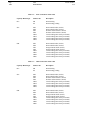
1.9.1
API Code Check results
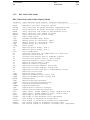
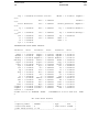
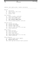
API Code Check results, Girder Capacity Model
Parameter (GIR) API Code Check Results, Parameter description
-------------------------------------------------------------------------UCmax
Maximum of all Unity Criterion factors
UCcbU
Unity Criterion for column buckling
UCbcbU
Unity Criterion for beam-column buckling
UCtfbU
Unity Criterion for torsional/flexural buckling
UCpbU
Unity Criterion for plastic bending
UCpdtw
Unity criterion, web plastic bending requirement
UCcdtw
Unity criterion, web compact section requirement
UCpbftf
Unity criterion, flange plastic bending requirement
UCcbftf
Unity criterion, flange compact section requirement
UClasup
Unity criterion, laterally unsupportet length, compr. flange
FSSLS
Factor of safety, SLS
FSULS
Factor of safety, ULS
sigx1
Normal stress in x direction
sigx2
Normal stress in y direction, edge 1
sigy
Normal stress in y direction, edge 2
tauxy
Shear stress
beta1
Plate slenderness; side1
beta2
Plate slenderness; side2
Cy1
Correction coefficient, y direction, side1
Cy2
Correction coefficient, y direction, side2
Le1
Effective plate flange, side 1
Le2
Effective plate flange, side 2
Ae
Effective cross section
zs
Distance from neutral axis to center of girder flange
zp
Distance from neutral axis to midplane of plate
Iez
Effective moment of inertia about z axis
re
Effective radius of gyration
Wep
Effective sectional modulus, plate side
Wes
Effective sectional modulus, flange side
Wpl
Plastic sectional modulus
J
Torsion constant
Cw
Warping constant
Is
Polar moment of inertia about shear center
Ic
Polar moment of inertia about centroid
P
Effective axial force
Ftw
Compressive force in the girder
Version number
1.0
Fwi
Mbend
lambda
PEe
PFu
Mu
B1
PTe
PTFe
PTFu
Mup
Rdtw
etapdtw
etacdtw
Rbftf
etapbft
etacbft
RLb
etaL1L2
Date
01-JUN-1991
Page
1-25
Assumed compressive force to be carried in the girder
Bending moment
Column slenderness
Elastic buckling force (Euler)
Ultimate column buckling resistance
Bending moment capacity
Bending amplification factor
Elastic torsional buckling force
Elastic torsional/flexural buckling force
Ultimate torsional/flexural buckling resistance
Ultimate plastic bending moment capacity
Web, height to thickness, bending ratio
Web, height to thickness, plastic bending ratio requirement
Web, height to thickness, compact section ratio requirement
Flange, height to thickness, bending ratio
Flange, height to thickness, plastic bending ratio requirement
Flange, height to thickness, compact seqtion ratio requirement
Laterally unsupported length of compression flange
Laterally unsupported length of compression flange requirement
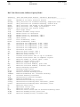
API Code Check results, Stiffener Capacity Model
Parameter (STF) API Code Check Results, Parameter description
-------------------------------------------------------------------------UCmax
Maximum of all Unity Criterion factors
UCcbU
Unity Criterion for column buckling
UCbcbU
Unity Criterion for beam-column buckling
UCtfbU
Unity Criterion for torsional/flexural buckling
UCpbU
Unity Criterion for plastic bending
UCpdtw
Unity criterion, web plastic bending requirement
UCcdtw
Unity criterion, web compact section requirement
UCpbftf
Unity criterion, flange plastic bending requirement
UCcbftf
Unity criterion, flange compact section requirement
UClasup
Unity criterion, laterally unsupported length, compr. flange
UCsreq
Unity criterion, moment of inertia, stiffener on panels, shear
UCsreql
Unity criterion, moment of inertia, stiffener cross sec., long
FSSLS
Factor of safety, SLS
FSULS
Factor of safety, ULS
sigx
Normal stress in x direction
sigy1
Normal stress in y direction, edge 1
sigy2
Normal stress in y direction, edge 2
tauxy
Shear stress
beta1
Plate slenderness; side1
beta2
Plate slenderness; side2
Cx1
Correction coefficient, x direction, side1
Cx2
Correction coefficient, x direction, side2
be1
Effective plate flange, side 1
be2
Effective plate flange, side 2
Ae
Effective cross section
zs
Distance from neutral axis to center of stiffener flange
Page
1-26
zp
Iez
re
Wep
Wes
Wpl
J
Cw
Is
Ic
P
Ftw
Fwi
Mbend
ms
lambda
ks
PEe
PFu
Mu
B1
PTe
PTFe
PTFu
Mup
Fxyu
Rdtw
etapdtw
etacdtw
Rbftf
etapbft
etacbft
RLb
etaL1L2
RIs
RIl
etaIe
Date
01-JUN-1991
Version number
1.0
Distance from neutral axis to midplane of plate
Effective moment of inertia about z axis
Effective radius of gyration
Effective sectional modulus, plate side
Effective sectional modulus, stiffener side
Plastic sectional modulus
Torsion constant
Warping constant
Polar moment of inertia about shear center
Polar moment of inertia about centroid
Effective axial force
Compressive force in the stiffener
Assumed compressive force to be carried in the stiffener
Bending moment
Bending moment factor
Column slenderness
Buckling length factor
Elastic buckling force (Euler)
Ultimate column buckling resistance
Bending moment capacity
Bending amplification factor
Elastic torsional buckling force
Elastic torsional/flexural buckling force
Ultimate torsional/flexural buckling resistance
Ultimate plastic bending moment capacity
Ultimate shear buckling resistance
Web, height to thickness, bending ratio
Web, height to thickness, plastic bending ratio requirement
Web, height to thickness, compact section ratio requirement
Flange, height to thickness, bending ratio
Flange, height to thickness, plastic bending ratio requirement
Flange, height to thickness, compact seqtion ratio requirement
Laterally unsupported length of compression flange
Laterally unsupported length of compression flange requirement
Moment of inertia for stiffeners, in-plane shear
Moment of inertia for longitudinal stiffeners
Requiremnt to moment of inertia for stiffeners
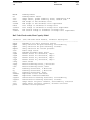
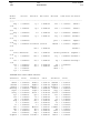
API Code Check results, Plate Capacity Model
Parameter (PLT) API Code Check Results, Parameter description
-------------------------------------------------------------------------UCmax
Maximum of all Unity Criterion factors
UCinplS
Unity Criterion for in-plane loads, SLS
UCinplU
Unity Criterion for in-plane loads, ULS
UCWeWa
Unity Criterion for elastic deflection
UCstrsS
Unity Criterion for stress due to lateral load, SLS
UCplatU
Unity Criterion for lateral load, ULS
FSSLS
Factor of safety, SLS
FSULS
Factor of safety, ULS
Version number
1.0
sigx1
sigx2
sigy1
sigy2
tauxy
fxe
fye
taue
kx
ky
ktau
feqb
fxs
fys
fxys
beta
fxu
fyu
fxyu
We
Wa
fxb
fyb
feqt
feqc
platu
Wp
Date
01-JUN-1991
Page
1-27
Normal stress in x direction, edge 1
Normal stress in x direction, edge 2
Normal stress in y direction, edge 1
Normal stress in y direction, edge 2
Shear stress
Elastic buckling stress, x direction
Elastic buckling stress, y direction
Elastic buckling stress, shear
Buckling coefficient for normal stress, x direction
Buckling coefficient for normal stress, y direction
Buckling coefficient for pure shear stress
Equivalent elastic buckling stress
Buckling resistance, x direction, SLS
Buckling resistance, y direction, SLS
Buckling resistance, shear, SLS
Plate slenderness
Buckling resistance, x direction ULS
Buckling resistance, y direction ULS
Buckling resistance, shear ULS
Elastic deflection
Maximum allowable elastic deflection
Maximum plate bending stress, x direcection
Maximum plate bending stress, y direcection
Equivalent stress at center of plate, tension side, SLS
Equivalent stress at center of plate, compression side, SLS
Ultimate uniform lateral pressure
Allowable permanent plastic deformation
API Code Check results, Uniaxially Stiffened Panel Capacity Model
Parameter
(USP) API Code Check Results, Parameter description
-------------------------------------------------------------------------UCmax
Maximum of all Unity Criterion factors
UCubucU
Unity Criterion for uniaxially stiffened panel buckling
FSSLS
Factor of safety, SLS
FSULS
Factor of safety, ULS
sigx
Average normal stress in x direction
lambda
Modified uniaxially stiffened panel slenderness
fu
Ultimate panel buckling resistance
Page
1-28
Date
01-JUN-1991
Version number
1.0
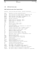
API Code Check results, Orthogonally Stiffened Panel Capacity Model
Parameter (OSP) API Code Check Results, Parameter description
-------------------------------------------------------------------------UCmax
Maximum of all Unity Criterion factors
UCinplS
Unity Criterion for in-plane loads, SLS
UCWeWa
Unity Criterion for elastic deflection
UCpstrS
Unity Criterion, service limit state stress, plate side
UCsstrS
Unity Criterion, service limit state stress, stiffener flange
UCgstrS
Unity Criterion, service limit state stress, girder flange
UCulatU
Unity Criterion, ultimate lateral load
FSSLS
Factor of safety, SLS
FSULS
Factor of safety, ULS
sigx
Average normal stress in x direction
sigy
Average normal stress in y direction
tauxy
Shear stress
fxse
Elastic buckling stress, x direction
fyse
Elastic buckling stress, y direction
Kx
Buckling coefficient, x direction
Ky
Buckling coefficient, y direction
eta
Torsional coefficient
betax
Plate slenderness, x side
betay
Plate slenderness, y side
Sxe
Effective plating acting with the stiffener, x direction
Sye
Effective plating acting with the stiffener, y direction
tx
Effective thickness acting with the stiffener, x direction
ty
Effective thickness acting with the stiffener, y direction
Ix
Moment of inertia of stiffener, effective plating, x direction
Iy
Moment of inertia of stiffener, effective plating, y direction
Ipx
Moment of inertia of effective plating alone, x direction
Ipy
Moment of inertia of effective plating alone, y direction
feqb
Equivalent elastic buckling stress
fxs
Buckling resistance in x direction
fys
Buckling resistance in y direction
We
Elastic deflection
Wa
Maximum allowable elastic deflection
delta
Deflection coefficient
fxbp
Panel bending stress, plate side, x direction
fybp
Panel bending stress, plate side, y direction
fxbs
Panel bending stress, stiffener side, x direction
fybs
Panel bending stress, stiffener side, y direction
Platu
Ultimate uniform pressure
Rc
Parameter for interaction forces, long./trans. stiffener
pc
Parameter of dimension load/length
Version number
1.0
1.9.2
Date
01-JUN-1991
Page
1-29
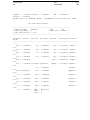
DnV Code Check results
DnV Code Check results, Girder Capacity Model
Parameter (GIR) DNV Code Check Results, Parameter description
-------------------------------------------------------------------------UCmax
Maximum of all Unity Criterion factors
UCcomp
Unity Criterion for girder buckling, compression side
UCtens
Unity Criterion for girder buckling, tension side
UCweb
Unity criterion, web heigth to web thickness ratio
UCffla
Unity criterion, free flange of girder
UCbfla
Unity criterion, box section flange
eta0
Basic usage factor
etap
Maximum allowable usage factor
sigx1
Normal stress in x direction, edge 1
sigx2
Normal stress in x direction, edge 2
sigy
Normal stress in y direction
tauxy
Shear stress
le1
Effective plate flange, side 1
le2
Effective plate flange, side 2
beta
Plate slenderness
Cx
Correction parameter for compression in x direction
Ae
Effective cross section
zp
Distance from neutral axis to midplane of plate
zf
Distance from neutral axis to top of flange
Iez
Effective moment of inertia about z axis
Iz
Moment of inertia about z axis
ie
Effective radius of gyration
wep
Effective sectional modulus, plate side
wef
Effective sectional modulus, flange side
P0
Equivalent lateral load due to longitudional stress
Pe
Effective lateral load
siga
Effective axial stress
sigbp
Effective bending stress, plate side
sigbf
Effective bending stress, flange side
Mbend
Bending moment
sigE
Elastic buckling resistance
sigET
Elastic torsional buckling stress
sigT
Torsional buckling resistance
lambda
Reduced slenderness
sigk
Characteristic material strength
sigacr
Characteristic buckling resistance
etac
Usage factor, girder stability check, compression side
etat
Usage factor, girder stability check, tension side
Rhwtw
Web height to web thickness ratio
etaweb
Web height to web thickness ratio requirement
Rfftf
Free flange to thickness of flange ratio
etaffla
Free flange to thickness of flange ratio requirement
Rbaftf
Box section flange to thickness of flange ratio
etabfla
Box section flange to thickness of flange ratio requirement
Page
1-30
Date
01-JUN-1991
Version number
1.0
DnV Code Check results, Stiffener Capacity Model
Parameter (STF) DNV Code Check Results, Parameter description
-------------------------------------------------------------------------UCmax
Maximum of all Unity Criterion factors
UCcomp
Unity Criterion for stiffener buckling, compression side
UCtens
Unity Criterion for stiffener buckling, tension side
UCweb
Unity criterion, web heigth to web thickness ratio
UCffla
Unity criterion, free flange of stiffener
UCbfla
Unity criterion, box section flange
eta0
Basic usage factor
etap
Maximum allowable usage factor
sigx
Normal stress in x direction
sigy1
Normal stress in y direction, edge 1
sigy2
Normal stress in y direction, edge 2
tauxy
Shear stress
beta1
Plate slenderness; side1
beta2
Plate slenderness; side2
Cx1
Correction for compression, x-dir, side1
Cx2
Correction for compression, x-dir, side2
Cy1
Correction for compression, y-dir, side1
Cy2
Correction for compression, y-dir, side2
Ctau
Correction for shear
se1
Effective plate flange, side 1
se2
Effective plate flange, side 2
Ae
Effective cross section
zs
Distance from neutral axis to top of stiffener
zp
Distance from neutral axis to midplane of plate
Iez
Effective moment of inertia about z axis
Iz
Moment of inertia about z axis
ie
Effective radius of gyration
Wep
Effective sectional modulus, plate side
Wes
Effective sectional modulus, stiffener side
sigE
Elastic buckling resistance
ks
Buckling length factor
Ctors
Torsional buckling coefficient
sigET
Elastic torsional buckling stress
lambdaT
Reduced slenderness wrt. torsional buckling
sigT
Torsional buckling resistance
sigk
Characteristic material strength
lambda
Reduced slenderness
sigacr
Characteristic buckling resistance
taucrg
Characteristic buckling shear resistance, global
taucrl
Characteristic buckling shear resistance, local
Nx
Effective axial force
p0
Equivalent lateral load
pe
Effective lateral load
siga
Effective axial stress used in stiffener buckling check
sigbp
Effective bending stress, plate side
sigbs
Effective bending stress, stiffener side
Version number
1.0
Mbend
ms
etac
etat
Rhwtw
etaweb
Rfftf
etaffla
Rbaftf
etabfla
Date
01-JUN-1991
Page
1-31
Bending moment
Bending moment factor
Usage factor, girder stability check, compression side
Usage factor, girder stability check, tension side
Web height to web thickness ratio
Web height to web thickness ratio requirement
Free flange to thickness of flange ratio
Free flange to thickness of flange ratio requirement
Box section flange to thickness of flange ratio
Box section flange to thickness of flange ratio requirement
DnV Code Check results, Plate Capacity Model
Parameter (PLT) DNV Code Check Results, Parameter description
-------------------------------------------------------------------------UCmax
Maximum of all Unity Criterion factors
UCpbs
Unity Criterion for plate buckling, serviceability
UCpbu
Unity Criterion for plate buckling, ultimate
UCplat
Unity Criterion for lateral pressure
eta0
Basic usage factor
etap
Maximum allowable usage factor
sigx1
Normal stress in x direction, edge 1
sigx2
Normal stress in x direction, edge 2
sigy1
Normal stress in y direction, edge 1
sigy2
Normal stress in y direction, edge 2
tauxy
Shear stress
sigex
Elastic buckling stress, x direction
sigey
Elastic buckling stress, y direction
taue
Elastic buckling stress, shear
Cx
Buckling coefficient, x direction
Cy
Buckling coefficient, y direction
Ctau
Buckling coefficient, shear
VonMise
Equivalent stress (Von Mises)
lambda
Equivalent reduced slenderness
sigescr
Characteristic buckling resistance, serviceability
sigeucr
Characteristic buckling resistance, ultimate
etas
Usage Factor for plate elements, serviceability criterion
etau
Usage Factor for plate elements, ultimate criterion
platu
Ultimate lateral pressure
Page
1-32
1.9.3
Date
01-JUN-1991
Version number
1.0
NPD Code Check results
NPD Code Check results, Girder Capacity Model
Parameter (GIR) NPD Code Check Results, Parameter description
-------------------------------------------------------------------------UCmax
Maximum of all Unity Criterion factors
UCcomp
Unity Criterion for girder buckling, compression side
UCtens
Unity Criterion for girder buckling, tension side
UCweb
Unity criterion, web heigth to web thickness ratio
UCffla
Unity criterion, free flange of girder
UCbfla
Unity criterion, box section flange
gammam
Material coefficient
sigx1
Normal stress in x direction, edge 1
sigx2
Normal stress in x direction, edge 2
sigy
Normal stress in y direction
tauxy
Shear stress
ae1
Effective plate flange, side 1
ae2
Effective plate flange, side 2
beta
Plate slenderness
Cx
Correction parameter for compression in x direction
Ae
Effective cross section
zp
Distance from neutral axis to midplane of plate
zf
Distance from neutral axis to top of flange
Iez
Effective moment of inertia about z axis
Iz
Moment of inertia about z axis
ie
Effective radius of gyration
wep
Effective sectional modulus, plate side
wef
Effective sectional modulus, flange side
P0
Equivalent lateral load due to longitudional stress
Pe
Effective lateral load
siga
Effective axial stress
sigbp
Effective bending stress, plate side
sigbf
Effective bending stress, flange side
Mbend
Bending moment
fe
Elastic buckling resistance
lambda
Reduced slenderness
fTi
Elastic torsional buckling stress
lambdaT
Reduced slenderness wrt. torional buckling
fkT
Torsional buckling resistance
fk
Characteristic buckling resistance
Rhwtw
Web height to web thickness ratio
etaweb
Web height to web thickness ratio requirement
Rfftf
Free flange to thickness of flange ratio
etaffla
Free flange to thickness of flange ratio requirement
Rbaftf
Box section flange to thickness of flange ratio
etabfla
Box section flange to thickness of flange ratio requirement
Version number
1.0
Date
01-JUN-1991
Page
1-33
NPD Code Check results, Stiffener Capacity Model
Parameter (STF) NPD Code Check Results, Parameter description
-------------------------------------------------------------------------UCmax
Maximum of all Unity Criterion factors
UCcomp
Unity Criterion for stiffener buckling, compression side
UCtens
Unity Criterion for stiffener buckling, tension side
UCweb
Unity criterion, web heigth to web thickness ratio
UCffla
Unity criterion, free flange of stiffener
UCbfla
Unity criterion, box section flange
gammam
Material coefficient
sigx
Normal stress in x direction
sigy1
Normal stress in y direction, edge 1
sigy2
Normal stress in y direction, edge 2
tauxy
Shear stress
beta1
Plate slenderness; side1
beta2
Plate slenderness; side2
Cx1
Correction for compression, x-dir, side1
Cx2
Correction for compression, x-dir, side2
Cy1
Correction for compression, y-dir, side1
Cy2
Correction for compression, y-dir, side2
Ctau
Correction for shear
be1
Effective plate flange, side 1
be2
Effective plate flange, side 2
Ae
Effective cross section
zs
Distance from neutral axis to top of stiffener
zp
Distance from neutral axis to midplane of plate
Iez
Effective moment of inertia about z axis
Iz
Moment of inertia about z axis
ie
Effective radius of gyration
Wep
Effective sectional modulus, plate side
Wes
Effective sectional modulus, stiffener side
fe
Elastic buckling resistance
ks
Buckling length factor
fTi
Elastic torsional buckling stress
lambdaT
Reduced slenderness wrt. torsional buckling
fkT
Torsional buckling resistance
lambda
Reduced slenderness
fk
Characteristic buckling resistance
sigg
Elastic global buckling stress with stiffeners removed
taucrg
Characteristic buckling shear resistance, global
taucrl
Characteristic buckling shear resistance, local
Nx
Effective axial force
siga
Effective axial stress used in stiffener buckling check
sigbp
Effective bending stress, plate side
sigbs
Effective bending stress, stiffener side
Mbend
Bending moment
ms
Bending moment factor
Rhwtw
Web height to web thickness ratio
etaweb
Web height to web thickness ratio requirement
Page
1-34
Rfftf
etaffla
Rbaftf
etabfla
Date
01-JUN-1991
Free flange
Free flange
Box section
Box section
to thickness of flange
to thickness of flange
flange to thickness of
flange to thickness of
Version number
1.0
ratio
ratio requirement
flange ratio
flange ratio requirement
NPD Code Check results, Plate Capacity Model
Parameter (PLT) NPD Code Check Results, Parameter description
-------------------------------------------------------------------------UCmax
Maximum of all Unity Criterion factors
UCpbs
Unity Criterion for plate buckling, serviceability
UCpbu
Unity Criterion for plate buckling, ultimate
UCplat
Unity Criterion for lateral pressure
gammam
Material coefficient
sigx1
Normal stress in x direction, edge 1
sigx2
Normal stress in x direction, edge 2
sigy1
Normal stress in y direction, edge 1
sigy2
Normal stress in y direction, edge 2
tauxy
Shear stress
sigex
Elastic buckling stress, x direction
sigey
Elastic buckling stress, y direction
taue
Elastic buckling stress, shear
kx
Buckling coefficient, x direction
ky
Buckling coefficient, y direction
ktau
Buckling coefficient, shear
VonMise
Equivalent stress (Von Mises)
lambda
Equivalent reduced slenderness
sigke
Characteristic buckling resistance, elastic
sigku
Characteristic buckling resistance, ultimate
sigked
Design buckling resistance, elastic
sigkud
Design buckling resistance, ultimate
platd
Ultimate lateral pressure
Version number
1.0
1.10
Date
01-JUN-1991
Page
1-35
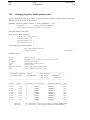
The results presentation
The previous sections described how the Code Check analyses were performed on the basis of the currently
selected Capacity Models and Resultcases, and how the Code Check results were stored in the database.
In order for the user to view these results, one of the results presentation commands must be used, i.e PRINT or
DISPLAY. The last display can also be saved on a plot file by use of the PLOT command.
Basic
Capacit Model
Optional
Reduced
Capacit Model
Load
Code Check
Results
Optional
Results
Presentation
Print
Figure 1-18
Display
Principles of result presentation
Page
1-36
1.10.1
Date
01-JUN-1991
Version number
1.0
Printing Code Check results
The Code Check results can in PLATEWORK be directed to either the screen or to a print file, by use of the
SET PRINT DESTINATION command, see Chapter 5.
Print levels
When printing Code Check results, several "print levels" are available:
Table 1.3
Code Check print levels
Print level
Description
SUMMARY
BRIEF
INTERMEDIATE
MEDIUM
FULL
Quick summary of all stored Code Check results
Brief listing of results, Capacity Model by Capacity Model
Intermediate Code Check results
Capacity Model geometry, loads and UC-factors
= MEDIUM + INTERMEDIATE
When printing Code Check results, the print level is selected in the PRINT command (e.g. PRINT CODECHECK-RESULTS SUMMARY).
Results sorting and filtering
The Code Check results can be sorted on the basis of any Code Check result parameter, by use of the DEFINE
SORTING PARAMETER command. If not specified, the default sorting parameter UCmax will be used.
Similarly, the user may define upper and lower limits to the value of the current sorting parameter, meaning
that those Capacity Models where the sorting parameter value is above maximum or below minimum will not
be printed. This is controlled by use of the DEFINE SORTING MIN-VALUE and DEFINE SORTING MAXVALUE.
Also, the user can control the order in which the sorting shall be performed, namely increasing or decreasing
order. This is controlled by the DEFINE SORTING ORDER command.
Finally, the printout can be limited by defining a maximum number of entries in a results print table, by use of
the DEFINE SORTING MAX-ENTRIES command.
The DEFINE SORTING command can be used both before or after running the Code Check analysis, the results will automatically be sorted whenever necessary.
Current selections
Results print can also be limited by use of the SELECT CAPACITY-MODEL and SELECT RESULTCASE
commands. Only those results which refer to a selected Capacity Model and a selected Resultcase will be
printed.
Version number
1.0
1.10.2
Date
01-JUN-1991
Page
1-37
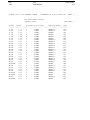
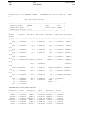
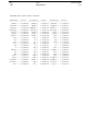
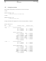
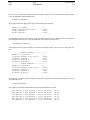
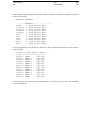
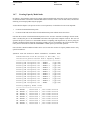
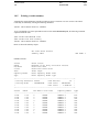
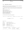
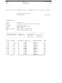
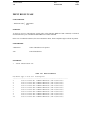
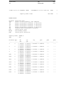
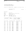
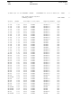
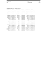
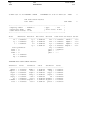
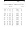
Summary print.
Below is shown an example of a summary print. Note the box where the current sorting definitions are shown.
06-MAY-1991 13:38 PROGRAM: SESAM
PLATEWORK D1.0-02 11-APR-1991
API Code Check Results
Summary Table
SUB PAGE: 1
NOMENCLATURE:
Status
UCmax
Res-Name
L-stat
Phas
Capacity-Model
Type
PAGE: 1
Check status
Maximum of all Unity Criterion factors
Resultcase name
Resultcase Limit-state
Phase angle
Basic Capacity Model name
Basic Capacity Model type
+-------------------------------------------------------------+
! Sorting Parameter: UCMAX
! Max Entries: UNLIMITED
!
! Sorting Order
: DECREASING
! Max Value : UNLIMITED
!
!
! Min Value : UNLIMITED
!
+-------------------------------------------------------------+
Status
UCmax
Res-Name L-stat Phas
Capacity-Model
Type
-----------------------------------------------------------------**-PB
5.18
2
STORM
XMANP2.2
PLT
**-PB
3.45
2
STORM
XMANP1.2
PLT
**-LB
3.05
3
STORM
XMANS2.2
STF
**-LB
3.05
4
STORM
XMANS2.2
STF
**-LB
3.05
1
STORM
XMANS2.1
STF
**-LB
3.05
2
STORM
XMANS2.1
STF
**-LB
3.05
3
STORM
XMANS2.1
STF
**-LB
3.05
4
STORM
XMANS2.1
STF
**-LB
3.05
1
STORM
XMANS2.2
STF
**-LB
3.05
2
STORM
XMANS2.2
STF
**-PB
2.84
4
STORM
XMANP2.2
PLT
**-LB
2.03
3
STORM
XMANS1.1
STF
**-LB
2.03
4
STORM
XMANS1.1
STF
**-LB
2.03
1
STORM
XMANS1.2
STF
**-LB
2.03
2
STORM
XMANS1.2
STF
**-LB
2.03
3
STORM
XMANS1.2
STF
**-LB
2.03
4
STORM
XMANS1.2
STF
**-LB
2.03
2
STORM
XMANS1.1
STF
**-LB
2.03
1
STORM
XMANS1.1
STF
**-PB
2.02
3
STORM
XMANP1.2
PLT
Page
1-38
Date
01-JUN-1991
06-MAY-1991 13:38 PROGRAM: SESAM
Version number
1.0
PLATEWORK D1.0-02 11-APR-1991
API Code Check Results
Summary Table
PAGE: 2
SUB PAGE: 2
Status
UCmax
Res-Name L-stat Phas
Capacity-Model
Type
-----------------------------------------------------------------**-PB
1.77
4
STORM
XMANP1.2
PLT
**-PB
1.69
1
STORM
XMANP2.2
PLT
**-LB
1.52
3
STORM
XMANG1
GIR
**-LB
1.52
1
STORM
XMANG1
GIR
**-LB
1.52
2
STORM
XMANG1
GIR
**-LB
1.52
4
STORM
XMANG1
GIR
**-PY
1.49
3
STORM
XMANP2.2
PLT
**-PB
1.07
2
STORM
XMANP2.1
PLT
OK-PB
0.92
4
STORM
XMANP2.1
PLT
OK-PB
0.58
3
STORM
XMANP2.1
PLT
OK-PB
0.56
2
STORM
XMANP1.1
PLT
OK-PB
0.55
1
STORM
XMANP1.2
PLT
OK-PB
0.52
2
STORM
XMANP1.3
PLT
OK-PB
0.47
3
STORM
XMANP1.3
PLT
OK-PB
0.46
2
STORM
XMANP2.3
PLT
OK-PB
0.41
1
STORM
XMANP2.3
PLT
OK-PB
0.39
3
STORM
XMANP1.1
PLT
OK-PB
0.34
4
STORM
XMANP1.1
PLT
OK-PY
0.31
4
STORM
XMANP2.3
PLT
OK-OPBE
0.28
2
STORM
XMANO
OSP
OK-PB
0.27
4
STORM
XMANP1.3
PLT
OK-PY
0.24
3
STORM
XMANP2.3
PLT
OK-PB
0.22
1
STORM
XMANP1.3
PLT
OK-PB
0.21
1
STORM
XMANP1.1
PLT
OK-OPBE
0.21
4
STORM
XMANO
OSP
OK-OPBE
0.18
3
STORM
XMANO
OSP
OK-PY
0.17
1
STORM
XMANP2.1
PLT
OK-OPBE
0.13
1
STORM
XMANO
OSP
Version number
1.0
Date
01-JUN-1991
Page
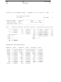
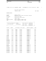
1-39
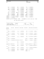
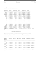
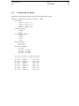
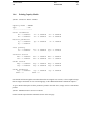
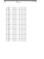
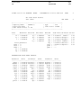
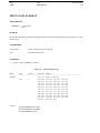
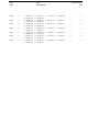
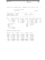
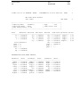
Minimum sorting parameter value applied
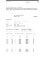
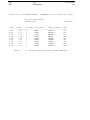
Below is shown the same summary printout, except that a sorting parameter minimum value=1.0 has been
defined, i.e. the table ignores all results that did not cause a failure. At the end of the table it is reported how
many instances were ignored,
06-MAY-1991 13:39 PROGRAM: SESAM
PLATEWORK D1.0-02 11-APR-1991
API Code Check Results
Summary Table
SUB PAGE: 1
NOMENCLATURE:
Status
UCmax
Res-Name
L-stat
Phas
Capacity-Model
Type
PAGE: 3
Check status
Maximum of all Unity Criterion factors
Resultcase name
Resultcase Limit-state
Phase angle
Basic Capacity Model name
Basic Capacity Model type
+-------------------------------------------------------------+
! Sorting Parameter: UCMAX
! Max Entries: UNLIMITED
!
! Sorting Order
: DECREASING
! Max Value : UNLIMITED
!
!
! Min Value : 1.000E+00
!
+-------------------------------------------------------------+
Status
UCmax
Res-Name L-stat Phas
Capacity-Model
Type
-----------------------------------------------------------------**-PB
5.18
2
STORM
XMANP2.2
PLT
**-PB
3.45
2
STORM
XMANP1.2
PLT
**-LB
3.05
3
STORM
XMANS2.2
STF
**-LB
3.05
4
STORM
XMANS2.2
STF
**-LB
3.05
1
STORM
XMANS2.1
STF
**-LB
3.05
2
STORM
XMANS2.1
STF
**-LB
3.05
3
STORM
XMANS2.1
STF
**-LB
3.05
4
STORM
XMANS2.1
STF
**-LB
3.05
1
STORM
XMANS2.2
STF
**-LB
3.05
2
STORM
XMANS2.2
STF
**-PB
2.84
4
STORM
XMANP2.2
PLT
**-LB
2.03
3
STORM
XMANS1.1
STF
**-LB
2.03
4
STORM
XMANS1.1
STF
**-LB
2.03
1
STORM
XMANS1.2
STF
**-LB
2.03
2
STORM
XMANS1.2
STF
**-LB
2.03
3
STORM
XMANS1.2
STF
**-LB
2.03
4
STORM
XMANS1.2
STF
**-LB
2.03
2
STORM
XMANS1.1
STF
**-LB
2.03
1
STORM
XMANS1.1
STF
Page
1-40
Date
01-JUN-1991
06-MAY-1991 13:38 PROGRAM: SESAM
Version number
1.0
PLATEWORK D1.0-02 11-APR-1991
API Code Check Results
Summary Table
SUB PAGE: 2
Status
UCmax
Res-Name L-stat Phas
Capacity-Model
Type
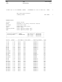
-----------------------------------------------------------------**-PB
2.02
3
STORM
XMANP1.2
PLT
**-PB
1.77
4
STORM
XMANP1.2
PLT
**-PB
1.69
1
STORM
XMANP2.2
PLT
**-LB
1.52
3
STORM
XMANG1
GIR
**-LB
1.52
1
STORM
XMANG1
GIR
**-LB
1.52
2
STORM
XMANG1
GIR
**-LB
1.52
4
STORM
XMANG1
GIR
**-PY
1.49
3
STORM
XMANP2.2
PLT
**-PB
1.07
2
STORM
XMANP2.1
PLT
Ignored:
PAGE: 4
20 Instances had sort parameter VALUE BELOW MIN
Version number
1.0
Date
01-JUN-1991
Page
1-41
Sorting parameter redefined
Below is shown a summary table based on another sorting parameter (UCbcbU, beam column buckling, see
box). Note that it is reported that some Capacity Models did not contain this parameter (in this case the plate
Capacity Models).
06-MAY-1991 13:43 PROGRAM: SESAM
PLATEWORK D1.0-02 11-APR-1991
API Code Check Results
PAGE: 5
NOMENCLATURE:
Status
UCbcbU
Res-Name
L-stat
Phas
Capacity-Model
Type
Check status
Unity Criterion for beam-column buckling
Resultcase name
Resultcase Limit-state
Phase angle
Basic Capacity Model name
Basic Capacity Model type
+-------------------------------------------------------------+
! Sorting Parameter: UCbcbU
! Max Entries: UNLIMITED
!
! Sorting Order
: DECREASING
! Max Value : UNLIMITED
!
!
! Min Value : UNLIMITED
!
+-------------------------------------------------------------+
Status
UCbcbU
Res-Name L-stat Phas
Capacity-Model
Type
-----------------------------------------------------------------**-LB
0.46
2
STORM
XMANS1.2
STF
**-LB
0.43
4
STORM
XMANS2.1
STF
**-LB
0.40
2
STORM
XMANS1.1
STF
**-LB
0.40
4
STORM
XMANS1.1
STF
**-LB
0.38
2
STORM
XMANS2.1
STF
**-LB
0.37
2
STORM
XMANS2.2
STF
**-LB
0.37
3
STORM
XMANS2.1
STF
**-LB
0.33
3
STORM
XMANS1.1
STF
**-LB
0.31
3
STORM
XMANS1.2
STF
**-LB
0.31
4
STORM
XMANS1.2
STF
**-LB
0.28
2
STORM
XMANG1
GIR
**-LB
0.24
1
STORM
XMANS2.2
STF
**-LB
0.23
1
STORM
XMANS2.1
STF
**-LB
0.20
4
STORM
XMANS2.2
STF
**-LB
0.20
3
STORM
XMANS2.2
STF
**-LB
0.19
1
STORM
XMANS1.1
STF
**-LB
0.16
1
STORM
XMANG1
GIR
**-LB
0.16
4
STORM
XMANG1
GIR
**-LB
0.15
3
STORM
XMANG1
GIR
**-LB
0.12
1
STORM
XMANS1.2
STF
Ignored:
28 Instances did not contain the SORT PARAMETER
Page
1-42
1.10.3
Date
01-JUN-1991
Version number
1.0
Brief print
On the following pages , examples of the BRIEF printout is shown. Note that here, the results are sorted on
the basis of both the Capacity Models and the current sorting parameter.
Check status
Unity Criterion Factors
Resultcase name
Phase angle
SUB PAGE:
FEATURES OF PLATEWORK 1
Status
Res-Name Phas UCmax UCcbU UCbcbU UCtfbU UCpbU UCpdtw UCcdtw UCpbftf UCcbftf UClasup UCsreq UCsreql
-------------------------------------------------------------------------------------------------------------**-LB
1
2.03
0.18
0.19
0.24
0.00
0.26
0.26
0.54
0.40
2.03
0.00
0.00
**-LB
2
2.03
0.38
0.40
0.51
0.01
0.34
0.34
0.54
0.40
2.03
0.01
0.00
**-LB
3
2.03
0.32
0.33
0.43
0.00
0.31
0.34
0.54
0.40
2.03
0.02
0.00
**-LB
4
2.03
0.37
0.40
0.50
0.02
0.33
0.34
0.54
0.40
2.03
0.01
0.00
Capacity Model: XMANS1.1
Type
: STF
Status
Res-Name Phas UCmax UCcbU UCbcbU UCtfbU UCpbU UCpdtw UCcdtw UCpbftf UCcbftf UClasup
----------------------------------------------------------------------------------------------**-LB
1
1.52
0.15
0.16
0.45
0.01
0.66
0.62
0.98
0.73
1.52
**-LB
2
1.52
0.26
0.28
0.77
0.01
0.76
0.90
0.98
0.73
1.52
**-LB
3
1.52
0.13
0.15
0.38
0.02
0.65
0.56
0.98
0.73
1.52
**-LB
4
1.52
0.13
0.16
0.39
0.02
0.65
0.57
0.98
0.73
1.52
Capacity Model: XMANG1
Type
: GIR
+-------------------------------------------------------------+
! Sorting Parameter: UCmax
! Max Entries: UNLIMITED
!
! Sorting Order
: DECREASING
! Max Value : UNLIMITED
!
!
! Min Value : 1.000E+00
!
+-------------------------------------------------------------+
Status
UC*
Res-Name
Phas
NOMENCLATURE:
API Code Check
Brief Table
0.28
0.31
0.38
0.02
0.29
0.34
0.54
0.40
2.03
0.00
0.00
1-44 FEATURES OF PLATEWORK
Status
Res-Name Phas UCmax UCcbU UCbcbU UCtfbU UCpbU UCpdtw UCcdtw UCpbftf UCcbftf UClasup UCsreq UCsreql
-------------------------------------------------------------------------------------------------------------**-LB
1
3.05
0.24
0.24
0.31
0.00
0.27
0.33
0.54
0.40
3.05
0.16
0.00
**-LB
2
3.05
0.34
0.37
0.44
0.02
0.30
0.34
0.54
0.40
3.05
0.18
0.00
**-LB
3
3.05
0.16
0.20
0.20
0.02
0.24
0.22
0.54
0.40
3.05
0.09
0.00
**-LB
4
3.05
0.15
0.20
0.19
0.03
0.24
0.21
0.54
0.40
3.05
0.12
0.00
Capacity Model: XMANS2.2
Type
: STF
Status
Res-Name Phas UCmax UCcbU UCbcbU UCtfbU UCpbU UCpdtw UCcdtw UCpbftf UCcbftf UClasup UCsreq UCsreql
-------------------------------------------------------------------------------------------------------------**-LB
1
3.05
0.23
0.23
0.30
0.00
0.27
0.32
0.54
0.40
3.05
0.08
0.00
**-LB
2
3.05
0.35
0.38
0.45
0.02
0.31
0.34
0.54
0.40
3.05
0.08
0.00
**-LB
3
3.05
0.35
0.37
0.46
0.01
0.31
0.34
0.54
0.40
3.05
0.01
0.00
**-LB
4
3.05
0.37
0.43
0.48
0.04
0.32
0.34
0.54
0.40
3.05
0.02
0.00
**-LB
4
2.03
Capacity Model: XMANS2.1
Type
: STF
Status
Res-Name Phas UCmax UCcbU UCbcbU UCtfbU UCpbU UCpdtw UCcdtw UCpbftf UCcbftf UClasup UCsreq UCsreql
-------------------------------------------------------------------------------------------------------------**-LB
1
2.03
0.12
0.12
0.16
0.00
0.24
0.20
0.54
0.40
2.03
0.01
0.00
**-LB
2
2.03
0.43
0.46
0.58
0.02
0.34
0.34
0.54
0.40
2.03
0.01
0.00
**-LB
3
2.03
0.31
0.31
0.41
0.00
0.30
0.34
0.54
0.40
2.03
0.01
0.00
Capacity Model: XMANS1.2
Type
: STF
4 Instances had sort parameter VALUE BELOW MIN
1 Instances had sort parameter VALUE BELOW MIN
4 Instances had sort parameter VALUE BELOW MIN
Ignored:
3 Instances had sort parameter VALUE BELOW MIN
Status
Res-Name Phas UCmax UCinplS UCinplU UCWeWa UCstrsS UCplatU
-------------------------------------------------------------------**-PB
2
1.07
1.07
0.54
0.08
0.37
0.01
Capacity Model: XMANP2.1
Type
: PLT
Ignored:
Status
Res-Name Phas UCmax UCinplS UCinplU UCWeWa UCstrsS UCplatU
--------------------------------------------------------------------
Capacity Model: XMANP1.3
Type
: PLT
Ignored:
Status
Res-Name Phas UCmax UCinplS UCinplU UCWeWa UCstrsS UCplatU
-------------------------------------------------------------------**-PB
2
3.45
3.45
0.80
0.37
0.37
0.02
**-PB
3
2.02
2.02
0.47
0.79
0.37
0.04
**-PB
4
1.77
1.77
0.40
0.79
0.36
0.04
Capacity Model: XMANP1.2
Type
: PLT
Ignored:
Status
Res-Name Phas UCmax UCinplS UCinplU UCWeWa UCstrsS UCplatU
--------------------------------------------------------------------
Capacity Model: XMANP1.1
Type
: PLT
FEATURES OF PLATEWORK 1
4 Instances had sort parameter VALUE BELOW MIN
1-46 FEATURES OF PLATEWORK
Ignored:
4 Instances had sort parameter VALUE BELOW MIN
Status
Res-Name Phas UCmax UCinplS UCWeWa UCpstrS UCsstrS UCgstrS UCulatU
----------------------------------------------------------------------------
Capacity Model: XMANO
Type
: OSP
Ignored:
Status
Res-Name Phas UCmax UCinplS UCinplU UCWeWa UCstrsS UCplatU
--------------------------------------------------------------------
Capacity Model: XMANP2.3
Type
: PLT
Status
Res-Name Phas UCmax UCinplS UCinplU UCWeWa UCstrsS UCplatU
-------------------------------------------------------------------**-PB
2
5.18
5.18
0.87
0.70
0.39
0.02
**-PB
4
2.84
2.84
0.48
1.49
0.42
0.05
**-PB
1
1.69
1.69
0.30
0.40
0.26
0.01
**-PY
3
1.49
1.37
0.26
1.49
0.39
0.05
Capacity Model: XMANP2.2
Type
: PLT
Version number
1.0
1.10.4
Date
01-JUN-1991
Page
1-47
Full print
On the following pages , examples of the FULL printout is shown. Note that here, each result entity (a
combination of a Capacity Model and a Resultcase) will normally fill a whole page.
Note also that here, it has been requested that the length of the print table shall be limited to 5 result entries
(Max Entries = 5, see box).
06-MAY-1991 13:57 PROGRAM: SESAM
PLATEWORK D1.0-02 11-APR-1991
API Code Check Results
Full Table
SUB PAGE: 1
NOMENCLATURE:
Girder
section
Material
Mat-Value
CM-Load
Load-Value
UC-Factor
UC-Val
PAGE: 1
Girder parameter name
Geometric dimension value
Capacity Model material parameter
Material parameter value
Capacity Model load
Load value
Unity Criterion factor
Unity Criterion factor value
+-------------------------------------------------------------+
! Sorting Parameter: UCmax
! Max Entries:
5
!
! Sorting Order
: DECREASING
! Max Value : UNLIMITED
!
!
! Min Value : UNLIMITED
!
+-------------------------------------------------------------+
Page
1-48
Date
01-JUN-1991
06-MAY-1991 13:57 PROGRAM: SESAM
2
Version number
1.0
PLATEWORK D1.0-02 11-APR-1991
PAGE:
API Code Check Results
+--------------------------------------------------------------+
! Capacity Model
: XMANG1
! Type
: GIR
!
! Resultcase Name : 1
! Limit-State: STORM
!
! Code Check Status: **-LB
!
!
+--------------------------------------------------------------+
Girder
section
Material Mat-Value CM-Load
Load-Value UC-Factor
UC-Val
-----------------------------------------------------------------------------hwg = 3.980E+02
fy = 3.400E+02
fx1 = -7.278E+02
UCmax =
1.52
twg = 1.200E+01
fp = 2.040E+02
fx2 = -5.541E+02
UCcbU =
0.15
bfg = 3.000E+02
E = 2.100E+05
fy1 = -5.818E+02 UCbcbU =
0.16
tfg = 2.200E+01
ny = 3.000E-01
fxy = 2.111E+02 UCtfbU =
0.45
afg = 0.000E+00
plat = -4.000E-03
UCpbU =
0.01
efg = 0.000E+00 Stiffener section
Mbend = -4.946E+06 UCpdtw =
0.66
hws = 1.480E+02
UCcdtw =
0.62
Plate dimension
tws = 1.200E+01
Girder parameter UCpbftf =
0.98
Ly = 5.000E+03
bfs = 9.000E+01
Lty = 5.000E+03 UCcbftf =
0.73
lx1 = 2.000E+03
tfs = 1.200E+01
kg = 1.000E+00 UClasup =
1.52
lx2 = 3.000E+03
afs = 0.000E+00
mg = 8.000E+00
t1 = 2.500E+01
efs = 3.900E+01
GTYP = 0
t2 = 2.500E+01
GSTF = 0
lya = 1.667E+03
INTERMEDIATE CODE CHECK RESULTS:
Parameter
Value
Parameter
Value
Parameter
Value
-------------------------------------------------------------UCmax = 1.524E+00
UCcbU = 1.530E-01 UCbcbU = 1.595E-01
UCtfbU = 4.495E-01
UCpbU = 5.527E-03 UCpdtw = 6.643E-01
UCcdtw = 6.181E-01 UCpbftf = 9.798E-01 UCcbftf = 7.316E-01
UClasup = 1.524E+00
FSSLS = 1.250E+00
FSULS = 1.500E+00
sigx1 = -2.784E+01
sigx2 = -2.120E+01
sigy = -1.969E+01
tauxy = 8.446E+00
beta1 = 3.219E+00
beta2 = 4.828E+00
Version number
1.0
Date
01-JUN-1991
Cy1 = 5.248E-01
Cy2 = 3.713E-01
Le1 = 1.050E+03
Le2 = 1.114E+03
Ae = 3.842E+04
zs = 3.228E+02
zp = 9.870E+01
Iez = 1.077E+09
re = 1.674E+02
Wep = 1.091E+07
Wes = 3.335E+06
Wpl = 4.170E+06
J = 1.294E+06
Cw = 5.023E+09
Is = 1.298E+09
Ic = 1.852E+08
P = -1.454E+06
Ftw = 5.278E+05
Fwi = 5.036E+05
Mbend = -4.946E+06 lambda = 3.826E-01
PEe = 8.926E+07
PFu = 1.426E+07
Mu = 1.134E+09
B1 = 1.000E+00
PTe = 5.242E+06
PTFe = 4.989E+06
PTFu = 4.854E+06
Mup = 1.342E+09
Rdtw = 3.317E+01
etapdtw = 4.993E+01 etacdtw = 5.366E+01
Rbftf = 1.364E+01
etapbft = 1.392E+01 etacbft = 1.864E+01
RLb = 5.000E+03
etaL1L2 = 3.281E+03
06-MAY-1991 13:57 PROGRAM: SESAM
PLATEWORK D1.0-02 11-APR-1991
Page
1-49
PAGE:
API Code Check Results
+--------------------------------------------------------------+
! Capacity Model
: XMANG1
! Type
: GIR
!
! Resultcase Name : 2
! Limit-State: STORM
!
! Code Check Status: **-LB
!
!
+--------------------------------------------------------------+
Girder
section
Material Mat-Value CM-Load
Load-Value UC-Factor
UC-Val
-----------------------------------------------------------------------------hwg = 3.980E+02
fy = 3.400E+02
fx1 = -1.317E+03
UCmax =
1.52
twg = 1.200E+01
fp = 2.040E+02
fx2 = -1.282E+03
UCcbU =
0.26
bfg = 3.000E+02
E = 2.100E+05
fy1 = -9.943E+02 UCbcbU =
0.28
tfg = 2.200E+01
ny = 3.000E-01
fxy = -2.097E+02 UCtfbU =
0.77
afg = 0.000E+00
plat = 7.000E-03
UCpbU =
0.01
efg = 0.000E+00 Stiffener section
Mbend = 1.108E+07 UCpdtw =
0.76
hws = 1.480E+02
UCcdtw =
0.90
Plate dimension
tws = 1.200E+01
Girder parameter UCpbftf =
0.98
Ly = 5.000E+03
bfs = 9.000E+01
Lty = 5.000E+03 UCcbftf =
0.73
lx1 = 2.000E+03
tfs = 1.200E+01
kg = 1.000E+00 UClasup =
1.52
lx2 = 3.000E+03
afs = 0.000E+00
mg = 8.000E+00
t1 = 2.500E+01
efs = 3.900E+01
GTYP = 0
t2 = 2.500E+01
GSTF = 0
Page
1-50
Date
01-JUN-1991
lya =
Version number
1.0
1.667E+03
INTERMEDIATE CODE CHECK RESULTS:
Parameter
Value
Parameter
Value
Parameter
Value
-------------------------------------------------------------UCmax = 1.524E+00
UCcbU = 2.615E-01 UCbcbU = 2.762E-01
UCtfbU = 7.682E-01
UCpbU = 1.358E-02 UCpdtw = 7.644E-01
UCcdtw = 9.017E-01 UCpbftf = 9.798E-01 UCcbftf = 7.316E-01
UClasup = 1.524E+00
FSSLS = 1.250E+00
FSULS = 1.500E+00
sigx1 = -5.036E+01
sigx2 = -4.902E+01
sigy = -3.365E+01
tauxy = -8.387E+00
beta1 = 3.219E+00
beta2 = 4.828E+00
Cy1 = 5.248E-01
Cy2 = 3.713E-01
Le1 = 1.050E+03
Le2 = 1.114E+03
Ae = 3.842E+04
zs = 3.228E+02
zp = 9.870E+01
Iez = 1.077E+09
re = 1.674E+02
Wep = 1.091E+07
Wes = 3.335E+06
Wpl = 4.170E+06
J = 1.294E+06
Cw = 5.023E+09
Is = 1.298E+09
Ic = 1.852E+08
P = -2.486E+06
Ftw = 5.241E+05
Fwi = 8.392E+05
Mbend = 1.108E+07 lambda = 3.826E-01
PEe = 8.926E+07
PFu = 1.426E+07
Mu = 1.134E+09
B1 = 1.000E+00
PTe = 5.242E+06
PTFe = 4.989E+06
PTFu = 4.854E+06
Mup = 1.224E+09
Rdtw = 3.317E+01
etapdtw = 4.339E+01 etacdtw = 3.678E+01
Rbftf = 1.364E+01
etapbft = 1.392E+01 etacbft = 1.864E+01
RLb = 5.000E+03
etaL1L2 = 3.281E+03
6-MAY-1991 13:57 PROGRAM: SESAM
PLATEWORK D1.0-02 11-APR-1991
4
PAGE:
API Code Check Results
+--------------------------------------------------------------+
! Capacity Model
: XMANG1
! Type
: GIR
!
! Resultcase Name : 3
! Limit-State: STORM
!
! Code Check Status: **-LB
!
!
+--------------------------------------------------------------+
Girder
section
Material Mat-Value CM-Load
Load-Value UC-Factor
UC-Val
-----------------------------------------------------------------------------hwg = 3.980E+02
fy = 3.400E+02
fx1 = -1.582E+03
UCmax =
1.52
twg = 1.200E+01
fp = 2.040E+02
fx2 = -4.173E+02
UCcbU =
0.13
bfg = 3.000E+02
E = 2.100E+05
fy1 = -4.932E+02 UCbcbU =
0.15
tfg = 2.200E+01
ny = 3.000E-01
fxy = -7.190E+01 UCtfbU =
0.38
afg = 0.000E+00
plat = -1.500E-02
UCpbU =
0.02
Version number
1.0
efg =
Date
01-JUN-1991
0.000E+00 Stiffener section
Page
1-51
Mbend = -1.478E+07
UCpdtw =
0.65
hws =
1.480E+02
tws =
1.200E+01
UCcdtw =
0.56
Plate dimension
Girder parameter
UCpbftf =
0.98
Ly =
5.000E+03
bfs =
9.000E+01
Lty =
5.000E+03 UCcbftf =
lx1 =
2.000E+03
tfs =
1.200E+01
kg =
1.000E+00 UClasup =
3.000E+03
2.500E+01
2.500E+01
1.667E+03
afs =
efs =
0.000E+00
3.900E+01
mg =
GTYP =
GSTF =
0.73
1.52
lx2
t1
t2
lya
=
=
=
=
8.000E+00
0
0
INTERMEDIATE CODE CHECK RESULTS:
Parameter
Value
Parameter
Value
Parameter
Value
-------------------------------------------------------------UCmax = 1.524E+00
UCcbU = 1.297E-01 UCbcbU = 1.493E-01
UCtfbU = 3.810E-01
UCpbU = 1.626E-02 UCpdtw = 6.461E-01
UCcdtw = 5.575E-01 UCpbftf = 9.798E-01 UCcbftf = 7.316E-01
UClasup = 1.524E+00
FSSLS = 1.250E+00
FSULS = 1.500E+00
sigx1 = -6.051E+01
sigx2 = -1.596E+01
sigy = -1.669E+01
tauxy = -2.876E+00
beta1 = 3.219E+00
beta2 = 4.828E+00
Cy1 = 5.248E-01
Cy2 = 3.713E-01
Le1 = 1.050E+03
Le2 = 1.114E+03
Ae = 3.842E+04
zs = 3.228E+02
zp = 9.870E+01
Iez = 1.077E+09
re = 1.674E+02
Wep = 1.091E+07
Wes = 3.335E+06
Wpl = 4.170E+06
J = 1.294E+06
Cw = 5.023E+09
Is = 1.298E+09
Ic = 1.852E+08
P = -1.233E+06
Ftw = 1.797E+05
Fwi = 7.872E+05
Mbend = -1.478E+07 lambda = 3.826E-01
PEe = 8.926E+07
PFu = 1.426E+07
Mu = 1.134E+09
B1 = 1.000E+00
PTe = 5.242E+06
PTFe = 4.989E+06
PTFu = 4.854E+06
Mup = 1.364E+09
Rdtw = 3.317E+01
etapdtw = 5.133E+01 etacdtw = 5.949E+01
Rbftf = 1.364E+01
etapbft = 1.392E+01 etacbft = 1.864E+01
RLb = 5.000E+03
etaL1L2 = 3.281E+03
06-MAY-1991 13:57 PROGRAM: SESAM
PLATEWORK D1.0-02 11-APR-1991
5
API Code Check Results
+--------------------------------------------------------------+
! Capacity Model
: XMANG1
! Type
: GIR
!
! Resultcase Name : 4
! Limit-State: STORM
!
! Code Check Status: **-LB
!
!
+--------------------------------------------------------------+
PAGE:
Page
1-52
Date
01-JUN-1991
Version number
1.0
Girder
section
Material Mat-Value CM-Load
Load-Value UC-Factor
UC-Val
-----------------------------------------------------------------------------hwg = 3.980E+02
fy = 3.400E+02
fx1 = -1.783E+03
UCmax =
1.52
twg = 1.200E+01
fp = 2.040E+02
fx2 = -2.161E+02
UCcbU =
0.13
bfg = 3.000E+02
E = 2.100E+05
fy1 = -5.082E+02 UCbcbU =
0.16
tfg = 2.200E+01
ny = 3.000E-01
fxy = -1.325E+02 UCtfbU =
0.39
afg = 0.000E+00
plat = 1.500E-02
UCpbU =
0.02
efg = 0.000E+00 Stiffener section
Mbend = 1.931E+07 UCpdtw =
0.65
hws = 1.480E+02
UCcdtw =
0.57
Plate dimension
tws = 1.200E+01
Girder parameter UCpbftf =
0.98
Ly = 5.000E+03
bfs = 9.000E+01
Lty = 5.000E+03 UCcbftf =
0.73
lx1 = 2.000E+03
tfs = 1.200E+01
kg = 1.000E+00 UClasup =
1.52
lx2 = 3.000E+03
afs = 0.000E+00
mg = 8.000E+00
t1 = 2.500E+01
efs = 3.900E+01
GTYP = 0
t2 = 2.500E+01
GSTF = 0
lya = 1.667E+03
INTERMEDIATE CODE CHECK RESULTS:
Parameter
Value
Parameter
Value
Parameter
Value
-------------------------------------------------------------UCmax = 1.524E+00
UCcbU = 1.336E-01 UCbcbU = 1.592E-01
UCtfbU = 3.926E-01
UCpbU = 2.130E-02 UCpdtw = 6.491E-01
UCcdtw = 5.669E-01 UCpbftf = 9.798E-01 UCcbftf = 7.316E-01
UClasup = 1.524E+00
FSSLS = 1.250E+00
FSULS = 1.500E+00
sigx1 = -6.819E+01
sigx2 = -8.268E+00
sigy = -1.720E+01
tauxy = -5.298E+00
beta1 = 3.219E+00
beta2 = 4.828E+00
Cy1 = 5.248E-01
Cy2 = 3.713E-01
Le1 = 1.050E+03
Le2 = 1.114E+03
Ae = 3.842E+04
zs = 3.228E+02
zp = 9.870E+01
Iez = 1.077E+09
re = 1.674E+02
Wep = 1.091E+07
Wes = 3.335E+06
Wpl = 4.170E+06
J = 1.294E+06
Cw = 5.023E+09
Is = 1.298E+09
Ic = 1.852E+08
P = -1.271E+06
Ftw = 3.311E+05
Fwi = 7.663E+05
Mbend = 1.931E+07 lambda = 3.826E-01
PEe = 8.926E+07
PFu = 1.426E+07
Mu = 1.134E+09
B1 = 1.000E+00
PTe = 5.242E+06
PTFe = 4.989E+06
PTFu = 4.854E+06
Mup = 1.360E+09
Rdtw = 3.317E+01
etapdtw = 5.109E+01 etacdtw = 5.850E+01
Rbftf = 1.364E+01
Version number
1.0
Date
01-JUN-1991
etapbft = 1.392E+01 etacbft = 1.864E+01
RLb = 5.000E+03
etaL1L2 = 3.281E+03
06-MAY-1991 13:57 PROGRAM: SESAM
PLATEWORK D1.0-02 11-APR-1991
6
Page
1-53
PAGE:
API Code Check Results
+--------------------------------------------------------------+
! Capacity Model
: XMANS1.1
! Type
: STF
!
! Resultcase Name : 1
! Limit-State: STORM
!
! Code Check Status: **-LB
!
!
+--------------------------------------------------------------+
Stiffener section
Material Mat-Value CM-Load
Load-Value UC-Factor
UC-Val
-----------------------------------------------------------------------------hws = 1.480E+02
fy = 3.400E+02
fx1 = -6.762E+02
UCmax =
2.03
tws = 1.200E+01
fp = 2.040E+02
fy1 = -3.498E+02
UCcbU =
0.18
bfs = 9.000E+01
E = 2.100E+05
fy2 = -4.289E+02 UCbcbU =
0.19
tfs = 1.200E+01
ny = 3.000E-01
fxy = 4.643E+00 UCtfbU =
0.24
afs = 0.000E+00
plat = -4.000E-03
UCpbU =
0.00
efs = 3.900E+01 Stiffener parameter
Mbend = 4.627E+05 UCpdtw =
0.26
Ly = 5.000E+03
UCcdtw =
0.26
Plate dimension
Ltx = 2.000E+03
UCpbftf =
0.54
lx = 2.000E+03
ks0 = 1.000E+00
UCcbftf =
0.40
ly1 = 1.250E+03
ms0 = 8.000E+00
UClasup =
2.03
ly2 = 2.500E+03
ksp = 6.000E-01
UCsreq =
0.00
t1 = 2.500E+01
msp = 1.600E+01
UCsreql =
0.00
t2 = 2.500E+01
SEND = Continous
STYP = 0
SSTF = 0
Page
1-54
Date
01-JUN-1991
INTERMEDIATE CODE CHECK RESULTS:
Parameter
Value
Parameter
Value
Parameter
Value
-------------------------------------------------------------UCmax = 2.032E+00
UCcbU = 1.818E-01 UCbcbU = 1.890E-01
UCtfbU = 2.442E-01
UCpbU = 3.643E-03 UCpdtw = 2.558E-01
UCcdtw = 2.649E-01 UCpbftf = 5.389E-01 UCcbftf = 4.024E-01
UClasup = 2.032E+00 UCsreq = 6.394E-04 UCsreql = 0.000E+00
FSSLS = 1.250E+00
FSULS = 1.500E+00
sigx = -2.549E+01
sigy1 = -1.399E+01
sigy2 = -1.716E+01
tauxy = 1.857E-01
beta1 = 2.012E+00
beta2 = 3.219E+00
Cx1 = 7.470E-01
Cx2 = 4.391E-01
be1 = 9.338E+02
be2 = 1.098E+03
Ae = 2.825E+04
zs = 1.547E+02
zp = 1.180E+01
Iez = 4.387E+07
re = 3.941E+01
Wep = 3.717E+06
Wes = 2.836E+05
Wpl = 6.253E+05
J = 1.371E+05
Cw = 1.644E+08
Is = 3.662E+07
Ic = 7.540E+06
P = -1.268E+06
Ftw = 8.655E+03
Fwi = 1.228E+05
Mbend = 4.627E+05
ms = 1.600E+01 lambda = 3.900E-01
ks = 6.000E-01
PEe = 6.314E+07
PFu = 1.046E+07
Mu = 9.642E+07
B1 = 1.000E+00
PTe = 1.450E+07
PTFe = 1.219E+07
PTFu = 7.788E+06
Mup = 1.905E+08
Fxyu = 1.941E+02
Rdtw = 1.233E+01 etapdtw = 4.822E+01
etacdtw = 4.656E+01
Rbftf = 7.500E+00 etapbft = 1.392E+01
etacbft = 1.864E+01
RLb = 2.000E+03 etaL1L2 = 9.842E+02
RIs = 2.805E+04
RIl = 0.000E+00
etaIe = 4.387E+07
Version number
1.0
Version number
1.0
1.10.5
Date
01-JUN-1991
Page
1-55
Displaying Code Check results
An alternative to printing the results, is to display them. Code Check results can be labelled on top of a Capacity
Model display. The user has the option of selecting a resultcase and a Code Check parameter.
Figure 1-19
Displaying Code Check results
Page
1-56
1.11
Date
01-JUN-1991
Version number
1.0
The data files
The two main datafiles in PLATEWORK are:
•
PLATEWORK database file
•
SESAM direct access results file (SIN-file)
The name of the SESAM
results file is stored on the
PLATEWORK
database,
enabeling the program to
automatically re-open the
SESAM results file in subsequent sessions.
PLATEWORK
DATABASE
PLATEWORK
SESAM
RESULTS
FILE
(DIRECT ACCESS)
Figure 1-20
Link to SESAM direct access results file from PLATEWORK database
Version number
1.0
1.11.1
Date
01-JUN-1991
Page
1-57
Database file
This file is opened by the program at the beginning of each session, either as a new file or as an old file (i.e.
created in a previous PLATEWORK session). The file is used in both READ & WRITE mode, and contains all
information necessary to perform a code check, for example :
a
Capacity Model geometry data
b
Capacity Model load data
c
Finite Element to Capacity Model transformation data
d
Code check results
1.11.2
SESAM results file (SIN-file)
This file is only used when a FE-model is referenced. The file is used in READ mode only, i.e. PLATEWORK
does not create, modifiy or delete any information in the SIN-file. The file is opened by PLATEWORK in the
following cases:
1
2
At the user’s request (READ command).
In this case the program will open the SIN-file and transfer vital information about the FEM model to the
PLATEWORK database file:
a
The full name of the SIN-file (to be used in subsequent sessions).
b
A list of superelements
c
A list of basic finite elements
d
A list of basic nodes
e
A list of beam cross sections
f
A list of materials
g
A list of resultcases
Automatically at the beginning of the session.
This requires that an old PLATEWORK database file is opened, and that the SIN-file was opened at the
user’s request in one of the previous sessions.
Version number
1.0
Date
01-JUN-1991
1
USER’S GUIDE TO PLATEWORK
1.1
Introduction
Page
1-1
This Chapter serves as a practical guide in using PLATEWORK, by providing a series of small command examples. The examples illustrate the concepts and principles discussed in the preceding Chapter, and the novice
user is therefore advised to read Chapters 1 and 2 first.
This Chapter does not explain practical aspects around program operation, as that is covered by Chapter 4.
1.2
Selecting Code of Practice
The current version supports API, DnV and NPD code checks, see the preceding chapters and the Theoretical
Manual. When opening a new database, the default Code of Practice will be DnV. If API or NPD is required,
this should be selected before other commands are used:
#SELECT CODE API
Selected design code changed:
From : DNV
To
: API
This selection will be saved on the database, i.e. the current Code of Practice will remain API for all subsequent PLATEWORK sessions that references this database, unless the SELECT CODE command is entered
again.
When later running a Code Check analysis (RUN CODE-CHECK-ANALYSIS) or printing results (PRINT
CODE-CHECK-RESULTS...), these commands will implicitely operate towards the currently selected Code of
Practice.
Page
1-2
Date
01-JUN-1991
1.3
Version number
1.0
Creating Capacity Models and loads manually
When creating Capacity Models manually, the following must have been created first:
1
Materials
2
Cross Sections
1.3.1
Creating Materials
When creating materials manually in PLATEWORK, the program will require parameters describing a limited
elastic material, see figure 1-1.
#CREATE MATERIAL GIR-MAT
LIMITED-ELASTIC 2.1E+05
#CREATE MATERIAL STF-MAT
LIMITED-ELASTIC 2.1E+05
#CREATE MATERIAL PLT-MAT
LIMITED-ELASTIC 2.1E+05
0.3 420.0
207.
0.3 345.0
207.
0.3 345.0
207.
Stress
Yield stress
Proportionality limit stress
Young’s modulus
Strain
Figure 1-1
Limited elastic material
Version number
1.0
Date
01-JUN-1991
Page
1-3
The materials can be printed:
#PRINT MATERIAL ALL
Name
Type
Parameter
Value
------------------------------------------------------------------GIR-MAT LIMITED-ELASTIC
Young’s modulus, E
2.100E+05
Poisson’s ratio, ny
3.000E-01
Yield strength, fy
4.200E+02
Pr. limit stress fp
2.070E+02
STF-MAT LIMITED-ELASTIC
Young’s modulus, E
Poisson’s ratio, ny
Yield strength, fy
Pr. limit stress fp
2.100E+05
3.000E-01
3.450E+02
2.070E+02
PLT-MAT LIMITED-ELASTIC
Young’s modulus, E
Poisson’s ratio, ny
Yield strength, fy
Pr. limit stress fp
2.100E+05
3.000E-01
3.450E+02
2.070E+02
Page
1-4
1.3.2
Date
01-JUN-1991
Version number
1.0
Creating Cross Sections
The user will have the opportunity to choose between several cross section types:
I-section:
#CREATE SECTION I-GIR
I 400.0 10.0 962.8 16.0 300.0 20.0
L-section:
#CREATE SECTION L-STF
L 160.0 10.0 90.0 10.0
For figures, and details on the mapping of cross sections onto Capacity Models, see Chapter 5.
#PRINT SECTION ALL
Name
Type
Parameter Value
Parameter Value
---------------------------------------------------------------I-GIR
I
Section Dimensions
HZ = 4.000E+02
TY = 1.000E+01
BT = 9.628E+02
TT = 1.600E+01
BB = 3.000E+02
TB = 2.000E+01
General section data
-void- = 0.000E+00
AREA =
IX = 2.907E+06
IY =
IZ = 1.235E+09
IYZ =
WXMIN = 1.453E+05 WYMIN =
WZMIN = 2.565E+06 SHARY =
SHARZ = 3.649E+03 SHCENY =
SHCENZ = 1.052E+02
SY =
SZ = 2.084E+06
L-STF
L
Section Dimensions
HZ = 1.600E+02
BY = 9.000E+01
TY =
TZ =
General section data
-void- = 0.000E+00
AREA
IX = 7.817E+04
IY
IZ = 1.520E+06
IYZ
WXMIN = 6.672E+03 WYMIN
WZMIN = 2.171E+04 SHARY
SHARZ = 1.165E+03 SHCENY
SHCENZ = -5.000E+01
SY
SZ = 2.450E+04
2.504E+04
6.922E+08
0.000E+00
2.537E+06
2.134E+04
0.000E+00
1.897E+06
1.000E+01
1.000E+01
= 2.400E+03
= 6.420E+06
= -1.800E+06
= 6.114E+04
= 6.204E+02
= -1.500E+01
= 5.513E+04
Version number
1.0
1.3.3
Date
01-JUN-1991
Creating Capacity Models
After having created materials and cross sections, the assembly can be created:
#CREATE ASSEMBLY-OF-CAPACITY-MODELS
ARBITRARY
-3000.0 -800.0 0.0
3000.0 -800.0 0.0
3000.0 800.0 0.0
-3000.0 800.0 0.0
GIRDERS MANUAL
1 EVEN
I-GIR
STIFFENERS MANUAL
1 EVEN
1 EVEN
L-STF
L-STF
PLATES MANUAL
20.0 20.0
20.0 20.0
MATERIALS MANUAL
GIR-MAT
STF-MAT STF-MAT
PLT-MAT PLT-MAT
PLT-MAT PLT-MAT
XCMA
Creation of Basic Capacity Models
=================================
Created : XCMAG1
(type GIR)
Created : XCMAS1.1
(type STF)
Created : XCMAS2.1
(type STF)
Created : XCMAP1.1
(type PLT)
Created : XCMAP1.2
(type PLT)
Created : XCMAP2.1
(type PLT)
Created : XCMAP2.2
(type PLT)
Page
1-5
Page
1-6
Date
01-JUN-1991
Version number
1.0
#DISPLAY CAPACITY-MODEL
Figure 1-2
A manually defined Capacity Model Assembly
#PRINT ASSEMBLY-OF-CAPACITY-MODELS XCMA
Capacity Model Assembly: XCMA
----------------------------Corner coordinates :
X1
X2
X3
X4
CMA dimensions
LX =
:
= -3.000E+03
= 3.000E+03
= 3.000E+03
= -3.000E+03
6.000E+03
Y1
Y2
Y3
Y4
= -8.000E+02
= -8.000E+02
= 8.000E+02
= 8.000E+02
LY = 1.600E+03
Z2
Z2
Z3
Z4
=
=
=
=
0.000E+00
0.000E+00
0.000E+00
0.000E+00
Version number
1.0
Date
01-JUN-1991
Number of girders:
Girder Spacing 1 :
Girder Spacing 2 :
Ngir = 1
3.000E+03 Nstf = 1
3.000E+03 Nstf = 1
Girder Spacing 1 :
Stiffener spacings:
s1.1 = 8.000E+02 s1.2 = 8.000E+02
Girder Spacing 2 :
Stiffener spacings:
s2.1 = 8.000E+02 s2.2 = 8.000E+02
#PRINT CAPACITY-MODEL XCMAP1.1
Capacity Model
: XCMAP1.1
Type
: PLT
---------------------------Corner
X1
X2
X3
X4
coordinates
= -3.000E+03
= 0.000E+00
= 0.000E+00
= -3.000E+03
Material parameters
fy = 3.450E+02
ny = 3.000E-01
Plate geometry
lx = 3.000E+03
Y1
Y2
Y3
Y4
= -8.000E+02
= -8.000E+02
= 0.000E+00
= 0.000E+00
Z1
Z2
Z3
Z4
=
=
=
=
0.000E+00
0.000E+00
0.000E+00
0.000E+00
fp = 2.070E+02
E = 2.100E+05
ly = 8.000E+02
t = 2.000E+01
Plate parameters
PTYP = 0
PSTF = 0
PDEF = 0
wa
= -1.000E+00 wp = -1.000E+00
Page
1-7
Page
1-8
1.3.4
Date
01-JUN-1991
Version number
1.0
Creating Resultcases
#CREATE RESULTCASE R1
’Manual example’ STATIC E-ULS BASIC
1.3.5
Creating Capacity Model loads
#CREATE LOAD-ON-CAPACITY-MODEL MANUAL XCMAP1.1 R1
fx1 -1800.0
fx2 -4000.0
fy1 -1200.0
fy2
600.0
fxy
600.0
plat
0.15
END
#CREATE LOAD-ON-CAPACITY-MODEL MANUAL XCMAS1.1 R1
fx1 -932.0
fy1 -76.0
fy2 -76.0
fxy 600.0
plat
0.04
END
#PRINT LOAD-ON-CAPACITY-MODEL ALL ALL
Capacity Model: XCMAP1.1
Type
: PLT
Res-Name Type
fx1
fy1
fxy
plat
pdfl
pbst
fx2
fy2
-------------------------------------------------------------------------R1
S
-1.800E+03 -1.200E+03 6.000E+02 1.500E-01
------4.000E+02 6.000E+02
Capacity Model: XCMAS1.1
Type
: STF
Res-Name Type
fx1
fy1
fxy
plat
Mbend
fy2
-------------------------------------------------------------------R1
S
-9.320E+02 -7.600E+01 6.000E+02 4.000E-02
----7.600E+01
Version number
1.0
Date
01-JUN-1991
#DISPLAY LOAD-ON-CAPACITY-MODEL XCMAP1.1 R1 NORMAL
Figure 1-3
A manually defined Capacity Model load
Page
1-9
Page
1-10
1.4
Date
01-JUN-1991
Version number
1.0
Creating Capacity Models and loads automatically from FEM-data
This section explains normal operations used when running PLATEWORK in the "postprocessor mode", i.e.
when the program can be viewed as a postprocessor to a Finite Element analysis.
1.4.1
Reading a SESAM Results Interface File (SIN-file)
In order to establish the link between the PLATEWORK database and the SESAM direct access results file, the
READ command is used. The program will read information about superelements, basic elements and nodes.
#READ SIN XMAN R10
Commenced reading SESAM results file
Reading superelement hierarchy
* NOTE: 1 new superelement index was imposed for s.el. type: 10
Reading element definitions
Reading node definitions
Calculating display window
Transferred 4 resultcase(s)
Transferred 2 beam cross section(s)
Transferred 1 material(s)
Completed reading SESAM results file
The name and prefix of the SIN-file (XMAN R10) will then be stored on the PLATEWORK database. In later
sessions referencing the same database, the SIN-file will be opened automatically before the main command
prompt # is made available to the user.
When using the READ command, the PLATEWORK database file will also inherit resultcases, cross sections
and materials from the SIN-file, thereby eliminating the need to use the commands CREATE RESULTCASE,
CREATE SECTION and CREATE MATERIAL as described in section 1.3.
The resultcases, cross sections and materials created in this way will be given default names:
Resultcase names
: 1, 2, 3, 4 ...
Cross section names : SEC-1, SEC-2, SEC-3 ...
Material names
: MAT-1, MAT-2, MAT-3 ...
Version number
1.0
1.4.2
Date
01-JUN-1991
Page
1-11
Displaying Finite Element Mesh
After successfully reading in the SIN-file, the Finite Element mesh can be displayed. In case of a multisuperelement model, all superelements will be displayed in the top level coordinate system:
#DISPLAY MESH
#LABEL ELEMENT-NUMBERS ON
Note that if beam elements exist in the model, they will be drawn with a slightly thicker line. This enables the
user to see where the beam elements are, and in most cases it is possible to recognise the stiffeners and girders
immediately.
Page
1-12
1.4.3
Date
01-JUN-1991
Version number
1.0
Using the SCOPE facilities
The Scope facility is used to limit the part of the Finite Element model which can be accessed. There are several options available to define Scopes, see Chapter 5 (SCOPE ELEMENT commands) for details.
An example may be that the user wants to see only the beams, in order to get a clear overview over the girders
and stiffeners within the model:
#SCOPE ELEMENT INCLUDE TYPE BEAM-2NODES
The included elements will be marked with small squares:
To confirm the scope and to see it displayed, enter the following:
#SCOPE ELEMENT CONFIRM DEFINED
#DISPLAY MESH
Version number
1.0
1.4.4
Date
01-JUN-1991
Page
1-13
Creating Capacity Models
After selecting the code, reading in the SIN-file, and optionally limiting the part of the FE-model that can be
accessed by use of the Scope facility, the Capacity Models can be created.
The most convenient way to do this is by pointing at nodes with the mouse or crosshair in the mesh display, in
order to define the Capacity Model Assembly corners (the corner nodes can also be identified by giving the
node numbers, see Chapter 5).
Below is shown the command to create a Capacity Model Assembly named "XMAN", which has its corners
defined by 4 nodes that are picked graphically from the FE-model.
#CREATE ASSEMBLY-OF-CAPACILTY-MODELS XMAN NODES PICK ...
PICK node 1 of 4
PICK node 2 of 4
PICK node 3 of 4
PICK node 4 of 4
Corner 4
Corner 1
Corner 3
Corner 2
At this stage, the Capacity Mode Assembly area has been defined, as well as the local coordinate system within
the assembly (x from Corner 1 to Corner 2, y from Corner 1 to Corner 4).
Page
1-14
Date
01-JUN-1991
Version number
1.0
The next step is to define the Girders within the assembly. In this case, beam elements exist in the FE-model,
so the AUTOMATIC option should be used:
... GIRDERS AUTOMATIC ...
The program reports how many girders were found, and the girder spacings:
Number
Girder
Girder
Girder
of girders
spacing scale factor
spacing 1
spacing 2
=
=
=
=
1
5000.
2000.
3000.
After defining the Girders, the Stiffeners in the two girder spacings must be defined. Again, beam elements
representing the stiffeners exist, so the AUTOMATIC option is the most convenient:
... STIFFENERS AUTOMATIC ...
The program reports how many stiffeners were found, and stiffener spacings. This is done for each girder spacing:
--------Number of
Stiffener
Stiffener
Stiffener
Stiffener
--------Number of
Stiffener
Stiffener
Stiffener
Stiffener
GIRDER SPACING 1 ------------stiffeners
= 2
spacing scale factor
= 5000.
spacing 1
= 1250.
spacing 2
= 2500.
spacing 3
= 1250.
GIRDER SPACING 2 ------------stiffeners
= 2
spacing scale factor
= 5000.
spacing 1
= 1250.
spacing 2
= 2500.
spacing 3
= 1250.
The next step is to define the plate thicknesses. This can be picked up from the shell elements by use of the
AUTOMATIC option:
... PLATES AUTOMATIC ...
The program will search in the FE-model and report the plate thicknesses found:
GIR
GIR
GIR
GIR
GIR
GIR
spacing
spacing
spacing
spacing
spacing
spacing
1,
1,
1,
2,
2,
2,
STF
STF
STF
STF
STF
STF
spacing
spacing
spacing
spacing
spacing
spacing
1,
2,
3,
1,
2,
3,
Plate
Plate
Plate
Plate
Plate
Plate
Thickness
Thickness
Thickness
Thickness
Thickness
Thickness
:
:
:
:
:
:
25.00
25.00
25.00
25.00
25.00
25.00
Version number
1.0
Date
01-JUN-1991
Page
1-15
Finally, materials must be assigned to the Girders, Stiffeners and Plates. Again, the AUTOMATIC option will
be the most convenient:
... MATERIALS AUTOMATIC
--------- MATERIALS --------------------Girder
1, using material MAT-1
Stiffener 1, using material MAT-1
Stiffener 2, using material MAT-1
Stiffener 3, using material MAT-1
Stiffener 4, using material MAT-1
Plate
1, using material MAT-1
Plate
2, using material MAT-1
Plate
3, using material MAT-1
Plate
4, using material MAT-1
Plate
5, using material MAT-1
Plate
6, using material MAT-1
Now, the program has received all necessary information, and it will proceed automatically to create the Basic
Capacity Models:
Creation of Basic Capacity Models
=================================
Created : XMANG1
(type GIR)
Created : XMANS1.1
(type STF)
Created : XMANS1.2
(type STF)
Created : XMANS2.1
(type STF)
Created : XMANS2.2
(type STF)
Created : XMANP1.1
(type PLT)
Created : XMANP1.2
(type PLT)
Created : XMANP1.3
(type PLT)
Created : XMANP2.1
(type PLT)
Created : XMANP2.2
(type PLT)
Created : XMANP2.3
(type PLT)
Created : XMANO
(type OSP)
Now, the program returns with the main command prompt "#", and the user is free to enter other commands,
see the following pages.
Page
1-16
1.4.5
Date
01-JUN-1991
Version number
1.0
Displaying Capacity Models
#DISPLAY CAPACITY-MODELS
It is also possible now to get more details about the Capacity Models created by printing the Capacity Model
gaometry data. On the next page is shown the command to print the geometry data of the girder Capacity
Model XMANG1 shown above.
Version number
1.0
1.4.6
Date
01-JUN-1991
Page
1-17
Printing Capacity Models
#PRINT CAPACITY-MODEL XMANG1
Capacity Model : XMANG1
Type
: GIR
---------------------Corner coordinates
X1 = 2.000E+03
X2 = 2.000E+03
Y1 = 0.000E+00
Y2 = 5.000E+03
Z1 = 0.000E+00
Z2 = 0.000E+00
fp = 2.040E+02
E = 2.100E+05
Plate geometry
Ly = 5.000E+03
t1 = 2.500E+01
lx1 = 2.000E+03
t2 = 2.500E+01
lx2 = 3.000E+03
lya = 1.667E+03
Stiffener section
hws = 1.480E+02
tfs = 1.200E+01
tws = 1.200E+01
afs = 0.000E+00
bfs = 9.000E+01
efs = 3.900E+01
Girder section
hwg = 3.980E+02
tfg = 2.200E+01
twg = 1.200E+01
afg = 0.000E+00
bfg = 3.000E+02
efg = 0.000E+00
Girder parameters
Lty = 5.000E+03
GTYP = 0
kg = 1.000E+00
GSTF = 0
mg = 8.000E+00
Material parameters
fy = 3.400E+02
ny = 3.000E-01
Note that the stiffener and girder section data shown here are mapped cross sections, i.e. there might be flanges
that are skipped. For details on cross section mappings, see the CREATE SECTION command in Chapter 5.
To get a detailed description of all the parameters printed in the table above, simply ask for a nomenclature
printout:
#PRINT NOMENCLATURE CAPACITY-MODEL
Extract from the output from this command is shown on the next page:
Page
1-18
Date
01-JUN-1991
Version number
1.0
Parameter (GIR) Capacity Model, Parameter description
------------------------------------------------------------------------Material
fy
fp
E
ny
Yield stress
Proportionality limit stress
Young’s modulus
Poisson’s ratio
Plate geometry
Ly
Length of girder, y direction
lx1
Girder spacing BEFORE girder
lx2
Girder spacing AFTER girder
t1
Plate thickness BEFORE girder
t2
Plate thickness AFTER girder
lya
Average stiffener spacing, y direction
Stiffener section
hws
Stiffener web height
tws
Stiffener web thickness
bfs
Stiffener flange width
tfs
Stiffener flange thickness
afs
Distance between webs (=0.0 if one web)
efs
Flange eccentricity
Girder section
hwg
Girder web height
twg
Girder web thickness
bfg
Girder flange width
tfg
Girder flange thickness
afg
Distance between webs (=0.0 if one web)
efg
Flange eccentricity
Girder parameters
Lty
Distance between lateral supports
kg
Buckling length factor
mg
Bending moment factor
GTYP Girder Type GSTF Stiffener Failure parameter
Version number
1.0
1.4.7
Date
01-JUN-1991
Page
1-19
Creating Capacity Model loads
In Chapter 2, the principles employed for creating Capacity Model loads on the basis of FE stresses and forces
are described. Below is shown the command that must be entered in order to activate this feature, and also the
following screen output produced by the program..
As described in Chapter 2, the process involves several operations, of which the 2 first are most important:
1
Creation of load transformation points
2
Creation of CM loads on the basis of load transformation points and FE stresses and forces.
Note that the creation of load transformation points involves extensive automatic searching in the FE model,
and it is usually this part of a PLATEWORK session that will require most computer resources. The user can
optimize this process (and save a considerable amount of computing and elapsed time) by actively using the
SCOPE command such that elements outside the assembly area are not included in the current element scope.
It may also be adviseable to submit PLATEWORK in a batch queue to perform this operation.
Note also that SELECT RESULTCASE can be used to limit the creation of Capacity Model loads to only
specified resultcases.
#CREATE LOAD-ON-CAPACITY-MODEL AUTOMATIC ASSEMBLY XMAN
Transformations from FE stresses to CM loads, i.e.
intersection points between mesh & Capacity Models
==================================================
Creating CM load points for : XMANG1
(type GIR)
Creating CM load points for : XMANS1.1
(type STF)
Creating CM load points for : XMANS1.2
(type STF)
Creating CM load points for : XMANS2.1
(type STF)
Creating CM load points for : XMANS2.2
(type STF)
Creating CM load points for : XMANP1.1
(type PLT)
Creating CM load points for : XMANP1.2
(type PLT)
Creating CM load points for : XMANP1.3
(type PLT)
Creating CM load points for : XMANP2.1
(type PLT)
Creating CM load points for : XMANP2.2
(type PLT)
Creating CM load points for : XMANP2.3
(type PLT)
Creating CM load points for : XMANO
(type OSP)
Creating Capacity Model loads
=============================
CM: XMANG1
, Resultcase 1 ,
CM: XMANS1.1 , Resultcase 1 ,
CM: XMANS1.2 , Resultcase 1 ,
CM: XMANS2.1 , Resultcase 1 ,
CM: XMANS2.2 , Resultcase 1 ,
CM: XMANP1.1 , Resultcase 1 ,
CM: XMANP1.2 , Resultcase 1 ,
CM: XMANP1.3 , Resultcase 1 ,
CM: XMANP2.1 , Resultcase 1 ,
New
New
New
New
New
New
New
New
New
loads
loads
loads
loads
loads
loads
loads
loads
loads
created
created
created
created
created
created
created
created
created
Page
1-20
Date
01-JUN-1991
CM:
CM:
CM:
CM:
CM:
CM:
CM:
CM:
CM:
CM:
CM:
CM:
CM:
CM:
CM:
CM:
CM:
CM:
CM:
CM:
CM:
CM:
CM:
CM:
CM:
CM:
CM:
CM:
CM:
CM:
CM:
CM:
CM:
CM:
CM:
CM:
CM:
CM:
CM:
XMANP2.2
XMANP2.3
XMANO
XMANG1
XMANS1.1
XMANS1.2
XMANS2.1
XMANS2.2
XMANP1.1
XMANP1.2
XMANP1.3
XMANP2.1
XMANP2.2
XMANP2.3
XMANO
XMANG1
XMANS1.1
XMANS1.2
XMANS2.1
XMANS2.2
XMANP1.1
XMANP1.2
XMANP1.3
XMANP2.1
XMANP2.2
XMANP2.3
XMANO
XMANG1
XMANS1.1
XMANS1.2
XMANS2.1
XMANS2.2
XMANP1.1
XMANP1.2
XMANP1.3
XMANP2.1
XMANP2.2
XMANP2.3
XMANO
,
,
,
,
,
,
,
,
,
,
,
,
,
,
,
,
,
,
,
,
,
,
,
,
,
,
,
,
,
,
,
,
,
,
,
,
,
,
,
Resultcase
Resultcase
Resultcase
Resultcase
Resultcase
Resultcase
Resultcase
Resultcase
Resultcase
Resultcase
Resultcase
Resultcase
Resultcase
Resultcase
Resultcase
Resultcase
Resultcase
Resultcase
Resultcase
Resultcase
Resultcase
Resultcase
Resultcase
Resultcase
Resultcase
Resultcase
Resultcase
Resultcase
Resultcase
Resultcase
Resultcase
Resultcase
Resultcase
Resultcase
Resultcase
Resultcase
Resultcase
Resultcase
Resultcase
1
1
1
2
2
2
2
2
2
2
2
2
2
2
2
3
3
3
3
3
3
3
3
3
3
3
3
4
4
4
4
4
4
4
4
4
4
4
4
,
,
,
,
,
,
,
,
,
,
,
,
,
,
,
,
,
,
,
,
,
,
,
,
,
,
,
,
,
,
,
,
,
,
,
,
,
,
,
New
New
New
New
New
New
New
New
New
New
New
New
New
New
New
New
New
New
New
New
New
New
New
New
New
New
New
New
New
New
New
New
New
New
New
New
New
New
New
Version number
1.0
loads
loads
loads
loads
loads
loads
loads
loads
loads
loads
loads
loads
loads
loads
loads
loads
loads
loads
loads
loads
loads
loads
loads
loads
loads
loads
loads
loads
loads
loads
loads
loads
loads
loads
loads
loads
loads
loads
loads
created
created
created
created
created
created
created
created
created
created
created
created
created
created
created
created
created
created
created
created
created
created
created
created
created
created
created
created
created
created
created
created
created
created
created
created
created
created
created
Version number
1.0
1.4.8
Date
01-JUN-1991
Page
1-21
Displaying Capacity Model loads
Any of the loads created in the preceding section can now be displayed, for example the membrane normal
loads on the girder XMANG1 in Resultcase 3:
#DISPLAY LOAD-ON-CAPACITY-MODEL XMANG1 3 NORMAL
Beam element forces
Note the dashed curves, showing the unreduced CM loads as described by the stresses and forces in the shell or
membrane elements within FE-model. It is also possible to recognize the beam element axial forces that are
included in the unreduced Capacity Model loads. The straight solid lines show the reduced Capacity Model
loads that are used in the Code Checks. The real numbers indicated at the start and end of each edge are the
start and end values of the reduced load on that edge.
Page
1-22
1.4.9
Date
01-JUN-1991
Version number
1.0
Printing Capacity Model loads
An alternative way of presenting the Capacity Model loads, is to print them. Below is shown how to print all
the reduced Capacity Model loads for the girder XMANG1. Compare the printout for resultcase 3 with the plot
shown in the preceding section.
#PRINT LOAD-ON-CAPACITY-MODEL XMANG1 ALL
NOMENCLATURE:
Res-Name
Type
fx1
fx2
fy1
fy2
fxy
plat
Mbend
pdfl
Resultcase name
Static or real/imaginary load component
Normal stress*plate thickness (x direction)
Normal stress*plate thickness (x direction)
Normal stress*plate thickness (y direction)
Normal stress*plate thickness (y direction)
In-plane shear stress*plate thickness
Lateral plate load
Beam bending moment
Lateral plate deflection
Capacity Model: XMANG1
Type
: GIR
Res-Name Type
fx1
fy1
fxy
plat
Mbend
fx2
-------------------------------------------------------------------1
S
-7.278E+02 -5.818E+02 2.111E+02 -4.000E-03 -4.946E+06
-5.541E+02
2
S
-1.317E+03 -9.943E+02 -2.097E+02 7.000E-03 1.108E+07
-1.282E+03
3
S
-1.582E+03 -4.932E+02 -7.190E+01 -1.500E-02 -1.478E+07
-4.173E+02
4
S
-1.783E+03 -5.082E+02 -1.325E+02 1.500E-02 1.931E+07
-2.161E+02
Version number
1.0
1.5
Date
01-JUN-1991
Page
1-23
Using the VIEW facility
The VIEW command contains a collection of operations for manipulating the graphics display:
1.5.1
Panning
Shifting the display in the plane of the screen:
#VIEW PAN <pick1> <pick2>
Pick 1
z
z
y
x
Pick 2
Figure 1-4
1.5.2
y
x
Using the VIEW PAN feature
Positioning
Implicit defininition of viewing direction by choosing an eye-point position in space. Viewing direction is
implicitely defined as being a vector starting at the eye-point and pointing towards the origin of the model
coordinate system. The vector is shifted in the plane of the screen such that the centre of the model roughly
coincides with the centre of the screen.
#VIEW POSITION 0.0 0.0 1.0
z
y
y
x
z
x
Page
1-24
Date
01-JUN-1991
Figure 1-5
1.5.3
Version number
1.0
Using the VIEW POSITION feature
Rotating
Absolute or relative rotations around model or screen axes.
#VIEW ROTATE X-AXIS 30.
30 deg.
z
y
z
y
x
x
Figure 1-6
Using the VIEW ROTATE X-AXIS feature
#VIEW ROTATE DOWN 30.
30 deg.
z
z
y
y
x
screen x-axis
x
Figure 1-7
Using the VIEW ROTATE DOWN feature
Version number
1.0
1.5.4
Date
01-JUN-1991
Zooming
Move closer to or further away from the model.
#VIEW ZOOM IN <pick1> <pick2>
pick2
z
z
y
y
pick1
x
x
Figure 1-8
Using the VIEW ZOOM IN feature
#VIEW ZOOM OUT <pick1> <pick2>
pick2
z
z
y
y
pick1
x
x
Figure 1-9
Using the VIEW ZOOM OUT feature
Page
1-25
Page
1-26
1.6
Date
01-JUN-1991
Version number
1.0
Selecting Capacity Models and Resultcases
The current selection of Capacity Models and Resultcases is controlled through the use of the SELECT
CAPACITY-MODEL and SELECT RESULTCASE commands:
1.6.1
Selecting Capacity Models
#SELECT CAPACITY-MODEL ALL OFF
ALL ( 11 ) CM(s) selected OFF
#SELECT CAPACITY-MODEL XMANG1 ON
CM XMANG1 selected ON
Currently selected : 1 of 11 CM(s)
#SELECT CAPACITY-MODEL XMANP1.1 ON
CM XMANP1.1 selected ON
Currently selected : 2 of 11 CM(s)
1.6.2
Selecting Resultcases
#SELECT RESULTCASE ALL OFF
ALL ( 4 ) Resultcase(s) selected OFF
#SELECT RESULTCASE 2 ON
Resultcase 2 selected ON
Currently selected : 1 of 4 resultcase(s)
#SELECT RESULTCASE 4 ON
Resultcase 4 selected ON
Currently selected : 2 of 4 resultcase(s)
Version number
1.0
1.7
Performing a Code Check
1.7.1
Defining Limit State Factors
Date
01-JUN-1991
Page
1-27
It is possible to modify the default limit state factors that are provided by the program, by use of the DEFINE
LIMIT-STATE-FACTOR command.
For example, the command to modify the basic usage factor η0 in the Ultimate Limit State (environmental
load) for the DnV Code Check is:
#DEFINE LIMIT-STATE-FACTOR DNV E-ULS 0.6
This factor will then be used in the DnV Code Check for all resultcases that have the E-ULS limit state kind
assigned.
1.7.2
Defining phase angle stepping for complex CM loads
When loads are complex, the following procedure will be used in the Code Checks:
•
The Code Check will be executed for all phase angles specified
•
The results will be stored for the phase angle that corresponded to the highest value of UCmax, the
maximum Unity Criterion factor.
The user decides which phase angles shall be used, either by:
1
Constant phase angle stepping
The user defines start angle, stop angle and angle step.
#DEFINE PHASE-ANGLE-STEPPING CONSTANT 0.0 350.0 10.0
2
Arbitrary phase angle stepping
The user defines all phase angles explicitely.
#DEFINE PHASE-ANGLE-STEPPING ARBITRARY 30.0 48.0 55.0 73.0 END
1.7.3
Running the Code Check Analysis
After possibly using SELECT RESULTCASE and/or SELECT CAPACITY-MODEL, the command to
perform the Code Check is:
#RUN CODE-CHECK-ANALYSIS
The Checks will be performed according to Code of Practice selected by previous use of the SELECT CODE
command.
Page
1-28
Date
01-JUN-1991
1.8
Printing Code Check results
1.8.1
Defining sorting parameter and sorting order
Version number
1.0
The user has complete control over which Code Check results parameter the results shall be sorted after, and
also the sorting order, by using the DEFINE SORTING commands.
The commands below show how to select the Code Check results parameter UCmax as the sorting parameter.
The results shall be sorted and printed in decreasing order according to the UCmax values.
#DEFINE SORTING PARAMETER UCmax
#DEFINE SORTING ORDER DECREASING
These two commands correspond to the default sorting definitions in PLATEWORK.
1.8.2
Defining print filters
In addition to defining the sorting parameter and sorting order, the user can define print filters to the results,
and thereby limit the amount of data printed to include only selected parts of the results.
A very useful filtering facility is the possibility to define upper and lower limits to the current sorting parameter
(defined by using DEFINE SORTING PARAMETER), causing results that correspond to a sorting parameter
value outside the selected range to be suppressed in the Code Check result print tables.
The commands below show how to limit the printout to include only failures, i.e. UCmax ≥ 1.0. Note that if
another sorting parameter is defined, the filters will be applied to that parameter.
#DEFINE SORTING MIN-VALUE 1.0
#DEFINE SORTING MAX-VALUE UNLIMITED
The user can, in addition to the above, define the maximum number of entries in the Code Check results print
table by use of the following command:
#DEFINE SORTING MAX-ENTRIES 10
This will then ensure that only the 10 "worst" failures will be printed (since the sorting order is defined to be
DECREASING).
1.8.3
Printing Code Check nomenclature
To see a complete list of Code Check result parameters, and their descriptions, the following command should
be used (nomenclature output examples are shown in Chapter 2):
#PRINT NOMENCLATURE CODE-CHECK-RESULTS
Version number
1.0
1.8.4
Date
01-JUN-1991
Page
1-29
Code Check status codes
For each result instance printed (i.e. combination of Capacity Model and Resultcase) there will be a "Status"
code included, indicating the status of the Code Check. The general layout of this "Status" will be:
**-<status-code>
OK-<status-code>
(when Code Check resulted in failure)
(when Code Check did not result in failure)
For an example on the use of status codes, see section 1.8.5.
The <status-code> is a short alphanumeric code indicating which check failed or which check was closest to
failure. The following three tables describe which status codes are relevant for the different Capacity Models /
Codes of Practice. The tables also describe the meaning of the alphanumeric codes.
Table 1.1
API Code Check status codes
Capacity Model Type
Status Code
Description
PLT
PB
PY
Plate buckling
Plate bending/yielding
STF
LB
CB
BCB
TFB
PLB
Local buckling
Column buckling
Beam-column buckling
Torsional/flexural buckling
Plastic bending
GIR
LB
CB
BCB
TFB
PLB
Local buckling
Column buckling
Beam-column buckling
Torsional/flexural buckling
Plastic bending
USP
OPBU
Overall panel buckling
OSP
OPBU
OPBE
Overall panel buckling
Overall panel bending
Page
1-30
Date
01-JUN-1991
Table 1.2
Version number
1.0
DnV Code Check status codes
Capacity Model Type
Status Code
Description
PLT
PB
PY
Plate buckling
Plate bending/yielding
STF
PIF1
PIF2
SIF1
SIF2
LB1P
LB1S
LB2P
LB2S
Plate induced failure (check1)
Plate induced failure (check2)
Stiffener induced failure (check1)
Stiffener induced failure (check2)
Local buckling (PIF1 check performed)
Local buckling (SIF1 check performed)
Local buckling (PIF2 check performed)
Local buckling (SIF2 check performed)
GIR
PIF1
PIF2
FIF1
FIF2
LB1P
LB1F
LB2P
LB2F
Plate induced failure (check1)
Plate induced failure (check2)
Flange induced failure (check1)
Flange induced failure (check2)
Local buckling (PIF1 check performed)
Local buckling (FIF1 check performed)
Local buckling (PIF2 check performed)
Local buckling (FIF2 check performed)
Table 1.3
NPD Code Check status codes
Capacity Model Type
Status Code
Description
PLT
PB
PY
Plate buckling
Plate bending/yielding
STF
PIF1
PIF2
SIF1
SIF2
LB1P
LB1S
LB2P
LB2S
Plate induced failure (check1)
Plate induced failure (check2)
Stiffener induced failure (check1)
Stiffener induced failure (check2)
Local buckling (PIF1 check performed)
Local buckling (SIF1 check performed)
Local buckling (PIF2 check performed)
Local buckling (SIF2 check performed)
GIR
PIF1
PIF2
FIF1
FIF2
LB1P
LB1F
LB2P
LB2F
Plate induced failure (check1)
Plate induced failure (check2)
Flange induced failure (check1)
Flange induced failure (check2)
Local buckling (PIF1 check performed)
Local buckling (FIF1 check performed)
Local buckling (PIF2 check performed)
Local buckling (FIF2 check performed)
Version number
1.0
1.8.5
Date
01-JUN-1991
Page
1-31
Printing a results summary
Assuming the sorting definitions from the preceding sections, a first short overview over the Code Check
results may be obtained by entering the following command:
#PRINT CODE-CHECK-RESULTS SUMMARY
To get a permanent copy of this print table stored on a file called xmansummary.lis, the following command
sequence should be used.
#SET PRINT DESTINATION FILE
#SET PRINT FILE xman summary
#PRINT CODE-CHECK-RESULTS SUMMARY
Below is shown the summary output:
API Code Check Results
Summary Table
SUB PAGE: 1
NOMENCLATURE:
Status
UCmax
Res-Name
L-stat
Phas
Capacity-Model
Type
Check status
Maximum of all Unity Criterion factors
Resultcase name
Resultcase Limit-state
Phase angle
Basic Capacity Model name
Basic Capacity Model type
+-------------------------------------------------------------+
! Sorting Parameter: UCmax
! Max Entries:
10
!
! Sorting Order
: DECREASING
! Max Value : UNLIMITED
!
!
! Min Value : 1.000E+00
!
+-------------------------------------------------------------+
Status
UCmax
Res-Name L-stat Phas
Capacity-Model
Type
-----------------------------------------------------------------**-PB
5.18
2
STORM
XMANP2.2
PLT
**-PB
3.45
2
STORM
XMANP1.2
PLT
**-LB
3.05
3
STORM
XMANS2.2
STF
**-LB
3.05
4
STORM
XMANS2.2
STF
**-LB
3.05
1
STORM
XMANS2.1
STF
**-LB
3.05
2
STORM
XMANS2.1
STF
**-LB
3.05
3
STORM
XMANS2.1
STF
**-LB
3.05
4
STORM
XMANS2.1
STF
**-LB
3.05
1
STORM
XMANS2.2
STF
**-LB
3.05
2
STORM
XMANS2.2
STF
Page
1-32
1.8.6
Date
01-JUN-1991
Version number
1.0
Printing further result details
Further details about the Code Check analysis may be obtained by use of the BRIEF, INTERMEDIATE,
MEDIUM and FULL options under PRINT CODE-CHECK-RESULTS.
Let us assume here that the summary print from the preceding section has been produced, and that the two
worst failures should be investigated in every detail. This can be done by use of the following command
sequence:
#SELECT RESULTCASE ALL OFF
#SELECT RESULTCASE 2 ON
#SELECT CAPACITY-MODEL ALL OFF
#SELECT CAPACITY-MODEL XMANP2.2 ON
#SELECT CAPACITY-MODEL XMANP1.2 ON
#SET PRINT DESTINATION FILE
#SET PRINT FILE XMAN WORST2
#PRINT CODE-CHECK-RESULTS FULL
This will then produce the following output on xmanworst2.lis:
12-MAY-1991 13:01 PROGRAM: SESAM
PLATEWORK D1.0-02 11-APR-1991
API Code Check Results
Full Table
SUB PAGE: 1
NOMENCLATURE:
Plate
dimension
Material
Mat-Value
CM-Load
Load-Value
UC-Factor
UC-Val
PAGE: 1
Plate parameter name
Geometric dimension value
Capacity Model material parameter
Material parameter value
Capacity Model load
Load value
Unity Criterion factor
Unity Criterion factor value
+-------------------------------------------------------------+
! Sorting Parameter: UCmax
! Max Entries:
10
!
! Sorting Order
: DECREASING
! Max Value : UNLIMITED
!
!
! Min Value : 1.000E+00
!
+-------------------------------------------------------------+
Version number
1.0
Date
01-JUN-1991
12-MAY-1991 13:01 PROGRAM: SESAM
Page
1-33
PLATEWORK D1.0-02 11-APR-1991
API Code Check Results
Full Table
PAGE:
2
SUB PAGE:
2
+--------------------------------------------------------------+
! Capacity Model
: XMANP1.2
! Type
: PLT
!
! Resultcase Name : 2
! Limit-State: STORM
!
! Code Check Status: **-PB
!
!
+--------------------------------------------------------------+
Plate
dimension Material Mat-Value CM-Load
Load-Value UC-Factor UC-Val
------------------------------------------------------------------------------lx = 2.000E+03
fy = 3.400E+02
fx1 = -1.290E+03
UCmax =
3.45
ly = 2.500E+03
fp = 2.040E+02
fx2 = -1.518E+03 UCinplS =
3.45
t = 2.500E+01
E = 2.100E+05
fy1 = -1.313E+03 UCinplU =
0.80
ny = 3.000E-01
fy2 = -8.471E+02 UCWeWa =
0.37
Plate parameter
fxy = 2.322E+01 UCstrsS =
0.37
PTYP = 0
plat = 7.000E-03 UCplatU =
0.02
PSTF = 0
pdfl = ---PDEF = 0
pbst = ---wa = -1.000E+00
wp = -1.000E+00
INTERMEDIATE CODE CHECK RESULTS:
Parameter
Value
Parameter
Value
Parameter
Value
-------------------------------------------------------------UCmax = 3.450E+00 UCinplS = 3.450E+00 UCinplU = 8.005E-01
UCWeWa = 3.665E-01 UCstrsS = 3.718E-01 UCplatU = 1.814E-02
FSSLS = 1.250E+00
FSULS = 1.500E+00
sigx1 = -5.159E+01
sigx2 = -6.073E+01
sigy1 = -5.251E+01
sigy2 = -3.388E+01
tauxy = 9.288E-01
fxe = 7.976E+01
fye = 1.186E+02
taue = 2.343E+02
kx = 2.690E+00
ky = 4.000E+00
ktau = 7.900E+00
feqb = 4.847E+01
fxs = 5.345E+01
fys = 4.111E+01
fxys = 1.680E+02
beta = 3.219E+00
fxu = 1.493E+02
fyu = 1.784E+02
fxyu = 1.805E+02
We = 2.545E+00
Wa = 6.944E+00
fxb = 9.313E+00
fyb = 1.110E+01
feqt = 4.152E+01
feqc = 6.068E+01
platu = 5.788E-01
Wp = 1.609E+01
Page
1-34
Date
01-JUN-1991
12-MAY-1991 13:01 PROGRAM: SESAM
Version number
1.0
PLATEWORK D1.0-02 11-APR-1991
API Code Check Results
Full Table
PAGE:
3
SUB PAGE:
3
+--------------------------------------------------------------+
! Capacity Model
: XMANP2.2
! Type
: PLT
!
! Resultcase Name : 2
! Limit-State: STORM
!
! Code Check Status: **-PB
!
!
+--------------------------------------------------------------+
Plate
dimension Material Mat-Value CM-Load
Load-Value UC-Factor UC-Val
------------------------------------------------------------------------------lx = 3.000E+03
fy = 3.400E+02
fx1 = -1.131E+03
UCmax =
5.18
ly = 2.500E+03
fp = 2.040E+02
fx2 = -1.108E+03 UCinplS =
5.18
t = 2.500E+01
E = 2.100E+05
fy1 = -9.237E+02 UCinplU =
0.87
ny = 3.000E-01
fy2 = -1.026E+03 UCWeWa =
0.70
Plate parameter
fxy = -3.213E+02 UCstrsS =
0.39
PTYP = 0
plat = 7.000E-03 UCplatU =
0.02
PSTF = 0
pdfl = ---PDEF = 0
pbst = ---wa = -1.000E+00
wp = -1.000E+00
INTERMEDIATE CODE CHECK RESULTS:
Parameter
Value
Parameter
Value
Parameter
Value
-------------------------------------------------------------UCmax = 5.183E+00 UCinplS = 5.183E+00 UCinplU = 8.729E-01
UCWeWa = 6.950E-01 UCstrsS = 3.875E-01 UCplatU = 2.408E-02
FSSLS = 1.250E+00
FSULS = 1.500E+00
sigx1 = -4.526E+01
sigx2 = -4.431E+01
sigy1 = -3.695E+01
sigy2 = -4.104E+01
tauxy = -1.285E+01
fxe = 7.592E+01
fye = 5.449E+01
taue = 1.541E+02
kx = 4.000E+00
ky = 2.871E+00
ktau = 8.118E+00
feqb = 3.280E+01
fxs = 3.482E+01
fys = 3.032E+01
fxys = 1.413E+02
beta = 4.024E+00
fxu = 1.480E+02
fyu = 1.284E+02
fxyu = 1.662E+02
We = 5.792E+00
Wa = 8.333E+00
fxb = 1.799E+01
fyb = 1.580E+01
feqt = 3.361E+01
feqc = 6.324E+01
platu = 4.360E-01
Wp = 2.012E+01
Ignored:
Ignored:
40 Instances referenced INACTIVE CM’s.
6 Instances referenced INACTIVE RESULTCASES.
Version number
1.0
1.9
Date
01-JUN-1991
Page
1-35
Displaying Code Check results
By investigation of the print tables produced in the preceding sections, we can conclude that the Code Check
Unity Criterion parameter UCinplS (Unity Criterion for in-plane loads, SLS) in resultcase 2 was the critical
one. This can be further illustrated through the use of graphics:
#SELECT CAPACITY-MODEL ALL
#DISPLAY CODE-CHECK-RESULTS 2 UCinplS
Page
1-36
1.10
Date
01-JUN-1991
Version number
1.0
Changing Capacity Model geometry data
After investigating the Code Check results, the user might wish to increase the plate thickness of the plate
XMANP2.2. This can be done as shown below:
#CHANGE CAPACITY-MODEL XMANP2.2 PLATE-GEOMETRY t 30.0
Parameter t
changed for CM XMANP2.2
Code Check Results deleted for this CM
The results must be re-calculated:
#RUN CODE-CHECK-ANALYSIS
Running API Code Check
Sorting PASS 1 of 3
Sorting PASS 2 of 3
Sorting PASS 3 of 3
A new summary print can be produced:
API Code Check Results
Summary Table
SUB PAGE: 1
NOMENCLATURE:
Status
UCmax
Res-Name
L-stat
Phas
Capacity-Model
Type
Check status
Maximum of all Unity Criterion factors
Resultcase name
Resultcase Limit-state
Phase angle
Basic Capacity Model name
Basic Capacity Model type
+-------------------------------------------------------------+
! Sorting Parameter: UCmax
! Max Entries:
10
!
! Sorting Order
: DECREASING
! Max Value : UNLIMITED
!
!
! Min Value : 1.000E+00
!
+-------------------------------------------------------------+
Status
UCmax
Res-Name L-stat Phas
Capacity-Model
Type
-----------------------------------------------------------------**-PB
3.45
2
STORM
XMANP1.2
PLT
**-LB
3.05
2
STORM
XMANS2.1
STF
**-LB
3.05
2
STORM
XMANS2.2
STF
**-LB
2.03
2
STORM
XMANS1.2
STF
**-LB
2.03
2
STORM
XMANS1.1
STF
**-PB
1.74
2
STORM
XMANP2.2
PLT
**-LB
1.52
2
STORM
XMANG1
GIR
**-PB
1.07
2
STORM
XMANP2.1
PLT
Ignored:
Ignored:
20 Instances had sort parameter VALUE BELOW MIN
17 Instances referenced INACTIVE RESULTCASES.
Version number
1.0
1.11
Date
01-JUN-1991
Page
1-37
Changing Capacity Model load data
The Code Check results were still not satisfactory after increasing the plate thickness. Another possibility is to
modify the Capacity Model load:
Figure 1-10
Original Capacity Model load
#CHANGE LOAD-ON-CAPACITY-MODEL MANUAL XMANP2.2 2
fx1 -800
fx2 -800
END
Results deleted for this CM and resultcase
CM load values stored
Figure 1-11
Modified Capacity Model load
Page
1-38
Date
01-JUN-1991
Version number
1.0
Again, the Code Check results must be re-calulated
#RUN CODE-CHECK-ANALYSIS
Running API Code Check
Sorting PASS 1 of 3
Sorting PASS 2 of 3
Sorting PASS 3 of 3
#PRINT CODE-CHECK-RESULTS SUMMARY
API Code Check Results
Summary Table
SUB PAGE: 1
NOMENCLATURE:
Status
UCmax
Res-Name
L-stat
Phas
Capacity-Model
Type
Check status
Maximum of all Unity Criterion factors
Resultcase name
Resultcase Limit-state
Phase angle
Basic Capacity Model name
Basic Capacity Model type
+-------------------------------------------------------------+
! Sorting Parameter: UCmax
! Max Entries:
10
!
! Sorting Order
: DECREASING
! Max Value : UNLIMITED
!
!
! Min Value : 1.000E+00
!
+-------------------------------------------------------------+
Status
UCmax
Res-Name L-stat Phas
Capacity-Model
Type
-----------------------------------------------------------------**-PB
3.45
2
STORM
XMANP1.2
PLT
**-LB
3.05
2
STORM
XMANS2.1
STF
**-LB
3.05
2
STORM
XMANS2.2
STF
**-LB
2.03
2
STORM
XMANS1.2
STF
**-LB
2.03
2
STORM
XMANS1.1
STF
**-LB
1.52
2
STORM
XMANG1
GIR
**-PB
1.33
2
STORM
XMANP2.2
PLT
**-PB
1.07
2
STORM
XMANP2.1
PLT
Ignored:
Ignored:
20 Instances had sort parameter VALUE BELOW MIN
17 Instances referenced INACTIVE RESULTCASES.
Version number
1.0
1.12
Date
01-JUN-1991
Page
1-39
Creating Resultcase combinations
Assume that a combination equal to the sum of resultcases 3 and 4 is required. This can be accomplished by
following this procedure:
Create the new resultcase:
#CREATE RESULTCASE C1 ’Resultcase 3 + RESULTCASE 4’ STATIC STORM
COMBINATION
3 1.0 0.0
4 1.0 0.0
END
Select the new resultcase:
#SELECT RESULTCASE ALL OFF
ALL ( 5 ) Resultcase(s) selected OFF
#SELECT RESULTCASE C1 ON
Resultcase C1 selected ON
Currently selected : 1 of 5 resultcase(s)
Create the new loads:
#CREATE LOAD-ON-CAPACITY-MODEL AUTOMATIC ALL
Creating Capacity Model loads
=============================
CM: XMANG1
, Resultcase
CM: XMANS1.1
, Resultcase
CM: XMANS1.2
, Resultcase
CM: XMANS2.1
, Resultcase
CM: XMANS2.2
, Resultcase
CM: XMANP1.1
, Resultcase
CM: XMANP1.2
, Resultcase
CM: XMANP1.3
, Resultcase
CM: XMANP2.1
, Resultcase
CM: XMANP2.2
, Resultcase
CM: XMANP2.3
, Resultcase
CM: XMANO
, Resultcase
#
C1
C1
C1
C1
C1
C1
C1
C1
C1
C1
C1
C1
,
,
,
,
,
,
,
,
,
,
,
,
New
New
New
New
New
New
New
New
New
New
New
New
loads
loads
loads
loads
loads
loads
loads
loads
loads
loads
loads
loads
created
created
created
created
created
created
created
created
created
created
created
created
Page
1-40
Date
01-JUN-1991
Version number
1.0
Below are shown plots illustrating the combinations that have been done on the basis of unreduced Capacity
Model loads:
Figure 1-12
Basic CM load, Resultcase 3
Figure 1-13
Basic CM load, Resultcase 4
Version number
1.0
Date
01-JUN-1991
Figure 1-14
Combination CM load, Resultcase C1
#RUN CODE-CHECK-ANALYSIS
Running API Code Check
Sorting PASS 1 of 3
Sorting PASS 2 of 3
Sorting PASS 3 of 3
#PRINT CODE-CHECK-RESULTS SUMMARY
Page
1-41
Page
1-42
Date
01-JUN-1991
12-MAY-1991 14:57 PROGRAM: SESAM
Version number
1.0
PLATEWORK D1.0-02 11-APR-1991
API Code Check Results
Summary Table
SUB PAGE: 1
NOMENCLATURE:
Status
UCmax
Res-Name
L-stat
Phas
Capacity-Model
Type
PAGE: 1
Check status
Maximum of all Unity Criterion factors
Resultcase name
Resultcase Limit-state
Phase angle
Basic Capacity Model name
Basic Capacity Model type
+-------------------------------------------------------------+
! Sorting Parameter: UCmax
! Max Entries:
10
!
! Sorting Order
: DECREASING
! Max Value : UNLIMITED
!
!
! Min Value : 1.000E+00
!
+-------------------------------------------------------------+
Status
UCmax
Res-Name L-stat Phas
Capacity-Model
Type
-----------------------------------------------------------------**-PB
7.58
C1
STORM
XMANP1.2
PLT
**-LB
3.05
C1
STORM
XMANS2.1
STF
**-LB
3.05
C1
STORM
XMANS2.2
STF
**-PB
2.96
C1
STORM
XMANP2.1
PLT
**-PB
2.74
C1
STORM
XMANP2.2
PLT
**-LB
2.03
C1
STORM
XMANS1.1
STF
**-LB
2.03
C1
STORM
XMANS1.2
STF
**-LB
1.52
C1
STORM
XMANG1
GIR
**-PB
1.11
C1
STORM
XMANP1.3
PLT
**-PB
1.06
C1
STORM
XMANP1.1
PLT
Ignored:
25 Instances referenced INACTIVE RESULTCASES.
Version number
1.0
Date
01-JUN-1991
1
EXECUTION OF PLATEWORK
1.1
Program Environment
1.1.1
Starting PLATEWORK
Page
1-1
The command required to start the execution of PLATEWORK is dependent on operating system and installation. A typical command used for a VAX/VMS installation may look like:
$RUN SESAM:PLATEWORK
The program will now display the program heading on the screen, see figure 1-1, page 1-2. The program heading contains important information such as program version number and release date. When reporting program
errors, the user should always refer to the program version number ("Program id") shown in the program heading:
The program will then invite the user to enter the prefix of the PLATEWORK database and journal files. The
default prefix is dependent on operating system of the current installation. The default prefix "[]" shown below
is used for a VAX/VMS installation.
Database & journal file prefix? /[]/ <Return>
When <Return> is pressed, the default prefix will be used by the progam.
The next step is to specify the name of the database and journal files. Again, the user can accept the default by
pressing the <Return> key:
Database & journal file name? /PLATEWORK/ <Return>
Page
1-2
Date
01-JUN-1991
******
********
**
**
**
*******
*******
**
**
**
********
******
******
********
**
**
**
**
**********
*********
**
**
**
********
******
******
********
**
**
**
*******
*******
**
**
**
********
******
Version number
1.0
******
********
**
**
**
*********
**********
**
**
**
**
*********
****** **
** *** ****
*************
**
**
**
**
**
**
**
**
**
**
**
**
**
**
**
**
**
**
**
**
**
**
**
**
*************************************************
*
*
*
P L A T E W O R K
*
*
*
*
Plate Structure Design & Code Checking
*
*
*
*************************************************
Marketing and Support by Veritas Sesam Systems
Program id
Release date
Access time
User id
Account
:
:
:
:
:
D1.0-02
Computer
11-APR-1991
Impl. update
15-MAY-1991 10:03:34 Operating system
CA
CPU id
VSS11391
Installation
:
:
:
:
:
VAXstation 3100/
None
VMS V5.4
0321622480
VSS GARM
Copyright Veritas Sesam Systems A.S, P.O.Box 300, N-1322 Hovik, Norway
Database & journal file prefix? /[]/ <return>
Database & journal file name? /PLATEWORK/ <return>
New or old database? /OLD/ NEW
Commencing PLATEWORK initialization.
Default graphics device : TX4014-15-16-54
Default design code
: DNV
Completed PLATEWORK initialization.
NEW journal file opened.
#
Figure 1-1
Starting PLATEWORK
Version number
1.0
Date
01-JUN-1991
Page
1-3
Finally, the user is requested to specify whether the PLATEWORK database already exists or if a new database
shall be created:
New or old? /OLD/ NEW <Return>
At this stage, the program will initialize the database file. This may require the user to wait for a few seconds
before the program prompt "#" appears, after which the commands described in Chapter 5 will be available.
1.1.2
Initial commands
Normally, the first command to enter when a new PLATEWORK database has been initialized is the SELECT
CODE command, for example:
#SELECT CODE API
In some cases, defaults used by the program will be dependent of the current Code of Practice, and the initial
use of SELECT CODE will ensure that valid defaults will be used. An example is when reasultcases are read
from a SIN-file and automatically assigned limit-states.
If there exists an FE-model which shall be used when creating Capacity Models, the next command would normally be READ-SIN-DIRECT-ACCESS, for example (for further details, please refer to Chapters 2 and 3.):
#READ SIN-DIRECT-ACCESS SINDIR:SESTRA R100
1.1.3
Startup files
On some computers, it is possible to prepare a PLATEWORK startup file containing commands that are automatically executed each time PLATEWORK is started. The format of this file is the same as any other Command Input File. An example of commands in a startup file may be:
SET DISPLAY DEVICE X-WINDOWS
SET DISPLAY WORKSTATION-WINDOW 28 120 8 100
SET PRINT PAGE-ORIENTATION PORTRAIT
This example shows how to automatically select the display device (in this case a workstation running under
the Xwindows system). A large display window is also defined. Finally, the PORTRAIT page orientation is
selected as default for the print files.
How to define startup files
This will be slightly different between different operating systems. In genereal, however, a logical name or environment variable called PLATEWORK_STARTUP must point to a PLATEWORK journal file containing
the startup commands. On VAX/VMS this is obtained by a command similar to:
$DEFINE PLATEWORK_STARTUP my_disk:[my_directory]PW_STARTUP.JNL
Please consult the PLATEWORK Status List (See Chapter 1 for information on how to get a copy) for other
Page
1-4
computers and operating systems.
Date
01-JUN-1991
Version number
1.0
Version number
1.0
1.1.4
Date
01-JUN-1991
Page
1-5
Entering commands / obtaining help
PLATEWORK uses the standard SESAM command processor, i.e. the following general SESAM command
features are available:
•
<Return> key
After typing in a command (optionally with subcommands) the <Return> key must be pressed in order to
have the specified command executed. The <Return> key can be pressed at any stage in a command sequence, in which case the program will prompt the user for the next subcommand and display the default
value of that subcommand.
•
Default values or alternatives
Often, the program offers a default value or a default alternative to the user. If a default is available, it will
be presented between two slashes after the command prompt:
This is the command prompt /This is the default/
To accept the default, the user can simply press the <Return> key.
•
Question mark
At any stage, the question mark "?" can be entered to get help on the current alternatives available. If entered at the main command level, all main commands will be listed.
#VIEW
Select VIEW option? /ROTATE/ ?
GIVE
FRAME
PAN
POSITION
ROTATE
ZOOM
Select VIEW option? /ROTATE/
•
Double dot
At any stage, two dots ".." can be entered to abort the current command. The program will return control to
the main command level.
#VIEW
Select VIEW option? /ROTATE/ ? ..
#
•
Semi-colon
If a semi-colon ";" is entered, the program will use the current default value presented and all default values for the following subcommands until there are no more subcommands with default values assigned. In
some cases, the program may prompt for input even if there is a default value. A second semi-colon may
then be entered to continue accepting the following default-values.
#VIEW ROTATE TO 90. ;
•
Abbreviations
Commands can be abbreviated as long as they are unique. Names cannot be abbreviated.
Page
1-6
1.2
Date
01-JUN-1991
Version number
1.0
Program Requirements
PLATEWORK can be used interactively or submitted in a batch queue. In principle, only an alphanumeric terminal is required, but if a graphics terminal or workstation is available, it is recommended to use the DISPLAY
features.
If the PostScript plot file format is used, access to a PostScript plotter is required.
1.2.1
Execution time
This depends heavily on which commands are used. In general, however, the CREATE LOAD-ONCAPACITY-MODEL AUTOMATIC command may require most time. Note the use of SCOPE ELEMENT in
connection with this feature.
1.2.2
Storage Space
In general, PLATEWORK does not require a lot of disk space for the database file. The SESAM results Interface file (SIN-file) usually requires more disk space than the PLATEWORK database file.
1.3
Program Limitations
1.3.1
Name limitations
Max length of Capacity Model Assembly name
Max length of Basic Capacity Model name
Max length of all other names
:
:
:
8
16
8
:
:
:
:
100
200
200
150
Names can not be abbreviated in the commands.
Names are stored in uppercase only.
1.3.2
Capacity Model size limitations
Max number of girders within an assembly
Max number of stiffeners within an assembly
Max number of plates within an assembly
Max number of elements along a CM edge
1.3.3
Code Check limitations
For limitations in the Code Checks, please refer to the Theoretical Manual.
(characters)
Version number
1.0
1
Date
01-JUN-1991
Page
1-1
COMMAND DESCRIPTION
The following notation is used in the description of the commands:
•
Uppercase words signify reserved commands.
Example:
•
Lowercase words enclosed in angle brackets "<>" within the commands signify parameters where an al
phanumeric or numerical value is expected.
Example:
•
PRINT RESULTCASE <RES-name>
Big parentheses "()" indicate selection between alternatives
Example:
•
PRINT
PRINT RESULTCASE
<RES-name>
ALL
Words enclosed in square brackets "[]" signify a parameter which is not always relevant.
Example:
DISPLAY LOAD-ON-CAPACITY-MODEL <BCM-name> ...
... <BCM-name> <RES-name> NORMAL
SHEAR
•
[ <angle> ]
Small parentheses "()" followed by multiplication sign indicate repeated input.
Example:
(<Typ> <Idx> <Nod>) *4
Page
1-2
Date
01-JUN-1991
1.1
Version number
1.0
CHANGE
COMMAND:
CHANGE
CAPACITY-MODEL ...
LOAD-ON-CAPACITY-MODEL ...
RESULTCASE ...
SIN-DIRECT-ACCESS ...
PURPOSE:
To modify objects in the PLATEWORK database, typically created by use of the CREATE command.
SUBCOMMANDS:
CAPACITY-MODEL
Change Capacity Model geometry, see "notes".
LOAD-ON-CAPACITY-MODEL
Change reduced Capacity Model load, see "notes".
RESULTCASE
Change Resultcase characteristics.
SIN-DIRECT-ACCESS
Change name of linked SIN-file.
NOTES:
1
Automatic deletion of Code-Check results
Whenever a Capacity Model or a Capacity Model Load is changed, any existing Code Check results will
be deleted.
See also:
CREATE ASSEMBLY-OF-CAPACITY-MODELS
CREATE LOAD-ON-CAPACITY-MODEL
CREATE RESULTCASE
READ SIN-DIRECT-ACCESS
Version number
1.0
Date
01-JUN-1991
Page
1-3
CHANGE CAPACITY-MODEL
SUBCOMMAND:
... CAPACITY-MODEL <BCM-name> <attribute> <name> [ <value> ]
PURPOSE:
To modify the overall geometry, material or cross section data in a basic Capacity Model previously created by
use of the CREATE ASSEMBLY-OF-CAPACITY-MODELS command.
PARAMETERS:
Note that the parameters of this command are dependent of the type of Capacity Model specified implicitely
through the Capacity Model name <BCM-name>, see note 1.
<BCM-name>
Name of Basic Capacity Model.
<attribute>
Type of data to be changed.
<attribute>
MATERIAL
PLATE-GEOMETRY
PLATE-PARAMETER
STIFFENER-SECTION
STIFFENER-PARAMETER
GIRDER-SECTION
GIRDER-PARAMETER
Description
Material data
Plate x & y lengths, plate thicknesses
Plate parameters
Stiffener cross section
Stiffener parameters
Girder cross section
Girder parameter
<name>
Name of material, cross section or single CM component.
<value>
Value of single CM component as described on the following pages.
NOTES:
1
Each Capacity Model type is explained separately
As the range of relevant attributes are different for each Capacity Model type, separate descriptions are
found on the following pages.
2
Results will be deleted
Any previously calculated Code Check results for the named Capacity Model will be deleted.
See also:
CREATE ASSEMBLY-OF-CAPACITY-MODELS
CHANGE LOAD-ON-CAPACITY-MODEL
Page
1-4
Date
01-JUN-1991
Version number
1.0
CHANGE CAPACITY-MODEL (PLT Capacity Models)
SUBCOMMAND:
... CAPACITY-MODEL <BCM-name> <attribute> <name> [ <value> ]
PURPOSE:
To modify the material, plate geometry or plate parameter data in a Capacity Model of type PLT (Plate).
PARAMETERS:
<BCM-name>
Name of Basic Capacity Model
<attribute>
Type of data to be changed, see below.
<name>
Name of material, cross section or single CM parameter.
<value>
Value of single CM parameter as described below.
<attribute>
MATERIAL
PLATE-GEOMETRY
PLATE-PARAMETER
<name>
<MAT-name>
<PGEO-name>
<PPAR-name>
<value>
<PGEO-value>
<PPAR-value>
MATERIAL
Modify the material data of the Capacity Model
<MAT-name>
Name of material from which new material data shall be fetched
PLATE-GEOMETRY
Modify the plate geometry data of the Capacity Model
<PGEO-name>
Name of plate geometry component, see below
<PGEO-value>
New value of plate geometry component
<PGEO-name>
lx
ly
t
<PGEO-value>
Length of plate, x direction
Length of plate, y direction
Plate thickness
PLATE-PARAMETER
Modify the plate parameter data of the Capacity Model
<PPAR-name>
Name of plate parameter component, see next page
<PPAR-value>
New value of plate parameter component
Version number
1.0
Date
01-JUN-1991
Page
1-5
<PPAR-name> <PPAR-value>
PTYP
Plate type
= 0: Simply supported along 4 edges
PSTF
Stiffener failure parameter
= 0: Plate edge stress reach yield before the stiffeners fail
= 1: Plate edge stress do not reach yield before the stiffeners fail.
PDEF
Deformation parameter
= 0: Permanent deformation allowed
= 1: Permanent deformation not allowed
wa
Max allowable elastic deformation
< 0: Not specified, use formulae in Theoretical Manual
> 0: Use specified value
wp
Max allowable plastic deformation
< 0: Not specified, use formulae in Theoretical Manual
> 0: Use specified value
NOTES:
1
Results will be deleted
Any previously calculated Code Check results for the referenced Capacity Model will be deleted on the
successful completion of this command.
EXAMPLES:
1
CHANGE CAPACITY-MODEL XMANP1.1 PLATE-GEOMETRY t 30.0
2
CHANGE CAPACITY-MODEL XMANP1.1 MATERIAL MAT-1
Page
1-6
Date
01-JUN-1991
Version number
1.0
CHANGE CAPACITY-MODEL (STF Capacity Models)
SUBCOMMAND:
... CAPACITY-MODEL <BCM-name> <attribute> <name> [ <value> ]
PURPOSE:
To modify the material, plate geometry, stiffener section or stiffener parameter data in a Capacity Model of
type STF (Stiffener).
PARAMETERS:
<BCM-name>
Name of Basic Capacity Model
<attribute>
Type of data to be changed, see below.
<name>
Name of material, cross section or single CM component
<value>
Value of single CM component
<attribute>
MATERIAL
PLATE-GEOMETRY
STIFFENER-SECTION
STIFFENER-PARAMETER
<name>
<MAT-name>
<PGEO-name>
<SEC-name>
<SPAR-name>
<value>
<PGEO-value>
<SPAR-value>
MATERIAL
Modify the material data of the Capacity Model
<MAT-name>
Name of material from which new material data shall be fetched
PLATE-GEOMETRY
Modify the plate geometry data of the Capacity Model
<PGEO-name>
Name of plate geometry component to be changed
<PGEO-value>
New value of plate geometry component
<PGEO-name>
lx
ly1
ly2
t1
t2
<PGEO-value>
length of stiffener, x direction
Stiffener spacing BEFORE stiffener
Stiffener spacing AFTER stiffener
Plate thickness BEFORE stiffener
Plate thickness AFTER stiffener
Version number
1.0
Date
01-JUN-1991
STIFFENER-SECTION
Modify the stiffener section data of the Capacity Model
<SEC-name>
Name of section from which new section data shall be fetched
Page
1-7
STIFFENER-PARAMETER Modify the stiffener parameter data of the Capacity Model
<SPAR-name>
Name of stiffener parameter component to be changed
<SPAR-value>
New value of stiffener parameter component
<SPAR-name> <SPAR-value>
Ly
Ltx
ks0
ms0
ksp
msp
Length of girder, y direction
Distance between lateral supports
Buckling length factor, without lateral load
Bending moment factor , without lateral load
Buckling length factor, including lateral load
Bending moment factor , including lateral load
SEND
End condition
CONTINUOUS (clamped at ends)
SNIPED
STYP
Stiffener Type
= 0: Panel (normal) stiffener
= 1: Transverse web stiffener type 1
= 2: Transverse web stiffener type 2
= 3: Longitudinal web stiffener
SSTF
Stiffener Failure parameter
= 0: Plate edge stresses reach yield before the stiffeners fail
= 1: Plate edge stresses do not reach yield before stiffeners fail
NOTES:
1
Results will be deleted
Any previously calculated Code Check results for the referenced Capacity Model will be deleted on the
successful completion of this command.
EXAMPLES:
1
CHANGE CAPACITY-MODEL XMANS1.1 STIFFENER-PARAMETER ks0 1.0
2
CHANGE CAPACITY-MODEL XMANS1.1 MATERIAL MAT-1
3
CHANGE CAPACITY-MODEL XMANS1.1 STIFFENER-SECTION SEC-2
Page
1-8
Date
01-JUN-1991
Version number
1.0
CHANGE CAPACITY-MODEL (GIR Capacity Models)
SUBCOMMAND:
... CAPACITY-MODEL <BCM-name> <attribute> <name> [ <value> ]
PURPOSE:
To modify the material, plate geometry, stiffener section, girder section or girder parameter data in a Capacity
Model of type GIR (Girder).
PARAMETERS:
<BCM-name>
Name of Basic Capacity Model
<attribute>
Type of data to be changed, see below.
<name>
Name of material, cross section or single CM component
<value>
Value of single CM component
<attribute>
MATERIAL
PLATE-GEOMETRY
STIFFENER-SECTION
GIRDER-SECTION
GIRDER-PARAMETER
<name>
<MAT-name>
<PGEO-name>
<SEC-name>
<SEC-name>
<GPAR-name>
MATERIAL
Modify the material data of the Capacity Model
<MAT-name>
Name of material from which new data shall be fetched
PLATE-GEOMETRY
Modify the plate geometry data of the Capacity Model
<PGEO-name>
Name of plate geometry component
<PGEO-value>
New value of plate geometry component
<PGEO-name>
Ly
lx1
lx2
t1
t2
lya
<value>
<PGEO-value>
<GPAR-value>
<PGEO-value>
Length of girder, y direction
Girder spacing BEFORE girder
Girder spacing AFTER girder
Plate thickness BEFORE girder
Plate thickness AFTER girder
Average stiffener spacing, y direction
Version number
1.0
Date
01-JUN-1991
STIFFENER-SECTION
Modify the stiffener section data of the Capacity Model
<SEC-name>
Name of section from which new data shall be fetched
GIRDER-SECTION
Modify the girder section data of the Capacity Model
<SEC-name>
Name of section from which new data shall be fetched
GIRDER-PARAMETER
Modify the girder parameter data of the Capacity Model
<GPAR-name>
Name of girder parameter component
<GPAR-value>
New value of girder parameter component
Page
1-9
<GPAR-name> <GPAR-value>
Lty
kg
mg
Distance between lateral supports
Buckling length factor
Bending moment factor
GTYP
Girder Type
= 0 : Panel (normal) girder
= 1 : Transverse web girder, type 1
= 2 : Transverse web girder, type 2
GSTF
Stiffener Failure parameter
= 0: Plate edge stresses reach yield before the girders fail
= 1: Plate edge stresses do not reach yield before the girders fail
NOTES:
1
Results will be deleted
Any previously calculated Code Check results for the referenced Capacity Model will be deleted on the
successful completion of this command.
EXAMPLES:
1
CHANGE CAPACITY-MODEL XMANG1 GIRDER-PARAMETER Lty 600.
2
CHANGE CAPACITY-MODEL XMANG1 PLATE-GEOMETRY t2 30.0
3
CHANGE CAPACITY-MODEL XMANG1 GIRDER-SECTION SEC-1
4
CHANGE CAPACITY-MODEL XMANG1 STIFFENER-SECTION SEC-2
Page
1-10
Date
01-JUN-1991
Version number
1.0
CHANGE CAPACITY-MODEL (USP Capacity Models)
SUBCOMMAND:
... CAPACITY-MODEL <BCM-name> <attribute> <name> [ <value> ]
PURPOSE:
To modify the material, plate geometry or stiffener section data in a Capacity Model of type USP (Uniaxially
Stiffened Panesls), used in API Code Checks.
PARAMETERS:
<BCM-name>
Name of Basic Capacity Model
<attribute>
Type of data to be changed, see below.
<name>
Name of material, cross section or single CM component
<value>
Value of single CM component
<attribute>
MATERIAL
PLATE-GEOMETRY
STIFFENER-SECTION
<name>
<MAT-name>
<PGEO-name>
<SEC-name>
MATERIAL
Modify the material data of the Capacity Model
<MAT-name>
Name of material from which new data shall be fetched
PLATE-GEOMETRY
Modify the plate geometry data of the Capacity Model
<PGEO-name>
Name of plate geometry component
<PGEO-value>
New value of plate geometry component
<PGEO-name>
Lx
Ly
lya
t
<value>
<PGEO-value>
<PGEO-value>
Length of panel, x direction
Length of panel, y direction
Average stiffener spacing, y direction
Plate thickness
STIFFENER-SECTION
Modify the stiffener section data of the Capacity Model
<SEC-name>
Name of section from which new data shall be fetched
Version number
1.0
Date
01-JUN-1991
Page
1-11
NOTES:
1
Results will be deleted
Any previously calculated Code Check results for the referenced Capacity Model will be deleted on the
successful completion of this command.
EXAMPLES:
1
CHANGE CAPACITY-MODEL XMANU PLATE-GEOMETRY lya 200.0
2
CHANGE CAPACITY-MODEL XMANU STIFFENER-SECTION SEC-2
3
CHANGE CAPACITY-MODEL XMANU MATERIAL MAT-1
Page
1-12
Date
01-JUN-1991
Version number
1.0
CHANGE CAPACITY-MODEL (OSP Capacity Models)
SUBCOMMAND:
... CAPACITY-MODEL <BCM-name> <attribute> <name> [ <value> ]
PURPOSE:
To modify the material, plate geometry, stiffener section or girder section in a Capacity Model of type OSP
(Orthogonally Stiffened Panel), used in API Code Checks.
PARAMETERS:
<BCM-name>
Name of Basic Capacity Model
<attribute>
Type of data to be changed, see below.
<name>
Name of material, cross section or single CM parameter.
<value>
Value of single CM parameter as described
<attribute>
MATERIAL
PLATE-GEOMETRY
GIRDER-SECTION
STIFFENER-SECTION
<name>
<MAT-name>
<PGEO-name>
<SEC-name>
<SEC-name>
MATERIAL
Modify the material data of the Capacity Model
<MAT-name>
Name of material from which new data shall be fetched
PLATE-GEOMETRY
Modify the plate geometry data of the Capacity Model
<PGEO-name>
Name of plate geometry component
<PGEO-value>
New Value of plate geometry component
<PGEO-name>
Lx
Ly
lxa
lya
t
<value>
<PGEO-value>
<PGEO-value>
Length of panel, x direction
Length of panel, y direction
Average girder spacing, x direction
Average stiffener spacing, y direction
Plate thickness
Version number
1.0
Date
01-JUN-1991
STIFFENER-SECTION
Modify the stiffener section data of the Capacity Model
<SEC-name>
Name of section from which new data shall be fetched
GIRDER-SECTION
Modify the girder section data of the Capacity Model
<SEC-name>
Name of section from which new data shall be fetched
Page
1-13
NOTES:
1
Results will be deleted
Any previously calculated Code Check results for the referenced Capacity Model will be deleted on the
successful completion of this command.
EXAMPLES:
1
CHANGE CAPACITY-MODEL XMANO PLATE-GEOMETRY t 30.0
2
CHANGE CAPACITY-MODEL XMANO STIFFENER-SECTION SEC-4
Page
1-14
Date
01-JUN-1991
Version number
1.0
CHANGE LOAD-ON-CAPACITY-MODEL
COMMAND:
CHANGE LOAD-ON-CAPACITY-MODEL AUTOMATIC ...
MANUAL ...
PURPOSE:
To modify basic Capacity Model loads previously created by use of the CREATE LOAD-ON-CAPACITYMODEL command.
SUBCOMMANDS:
AUTOMATIC
Automatic re-calculation of reduced Capacity Model loads from the unreduced loads
MANUAL
Manual re-definition of reduced Capacity Model loads.
NOTES:
1
Results will be deleted
Any previously calculated Code Check results for the referenced combination of Capacity Models and resultcases will be deleted on the successful completion of this command.
See also:
CREATE LOAD-ON-CAPACITY-MODEL
CREATE RESULTCASE
CHANGE RESULTCASE
READ SIN-DIRECT-ACCESS
CHANGE CAPACITY-MODEL
Version number
1.0
Date
01-JUN-1991
Page
1-15
CHANGE LOAD-ON-CAPACITY-MODEL AUTOMATIC
SUBCOMMAND:
... AUTOMATIC ASSEMBLY <CMA-name>
ALL
PURPOSE:
To re-calculate the reduced Capacity Model loads from the unreduced loads, typically following previous
manual re-definition of the loads, by use of CHANGE LOAD-ON-CAPACITY-MODEL MANUAL. See
Chapter 2 for more details on calculation of Capacity Model loads.
PARAMETERS:
ASSEMBLY
Re-calculate the loads for the basic Capacity Models within the specified Capacity
Model Assembly.
ALL
Re-calculate the loads for all basic Capacity Models.
NOTES:
1
Loads must have been created using AUTOMATIC option
When CM loads are created through the CREATE LOAD-ON-CAPACITY-MODEL AUTOMATIC
command, both unreduced and reduced loads will be stored. When the CHANGE LOAD-ONCAPACITY-MODEL MANUAL command is used, only the reduced loads will be changed. The
CHANGE LOAD-ON-CAPACITY-MODEL AUTOMATIC command can then be used to re-calculate
the original reduced loads on the basis of the original unreduced loads.
2
Results will be deleted
Any previously calculated Code Check results for the referenced combination of Capacity Models and resultcases will be deleted on the successful completion of this command.
EXAMPLES:
1
CHANGE LOAD-ON-CAPACITY-MODEL AUTOMATIC ALL
2
CHANGE LOAD-ON-CAPACITY-MODEL AUTOMATIC ASSEMBLY XMAN
3
See Chapter 3
Page
1-16
Date
01-JUN-1991
Version number
1.0
CHANGE LOAD-ON-CAPACITY-MODEL MANUAL
SUBCOMMAND:
... MANUAL <BCM-name> <RES-name> <component> <new_value>
END
PURPOSE:
To modify the reduced Capacity Model load of a basic Capacity Model previously created by use of CREATE
LOAD-ON-CAPACITY-MODEL (MANUAL or AUTOMATIC options).
PARAMETERS:
<BCM-name>
<RES-name>
Name of Basic Capacity Model
Name of Resultcase
<component>
Name of Capacity Model load component. Note that the range of Capacity Model
load components available is dependent on the type of Capacity Model specified
implicitely through the Capacity Model name (<BCM-name>).
Table 1.1
Load Components relevant for different CM types
<component>
fx1
fx2
fy1
fy2
fxy
plat
Mbend
pdfl
pbst
END
PLT
x
x
x
x
x
x
STF
x
x
x
x
x
x
x
x
End of component selection
GIR
x
x
x
x
x
x
USP
x
OSP
x
x
x
Version number
1.0
Date
01-JUN-1991
Page
1-17
Table 1.2
Description of load components
<component>
fx1
fx2
fy1
fy2
fxy
plat
Mbend
pdfl
pbst
Description
Membrane normal load in local x-direction
Membrane normal load in local x-direction
Membrane normal load in local y-direction
Membrane normal load in local y-direction
Membrane shear load
Lateral plate load
Girder or Stiffener bending moment
Local plate deflection
plate bending load
Table 1.3
Unit description for load components
<component>
fx1
fx2
fy1
fy2
fxy
plat
Mbend
pdfl
pbst
<new_value>
Unit description
Force / Capacity Model edge length
Force / Capacity Model edge length
Force / Capacity Model edge length
Force / Capacity Model edge length
Force / Capacity Model edge length
Force / Capacity Model plate area
Force * length
Length
Force / Capacity Model edge length
New value of Capacity Model load component.
Note that the new value of a Capacity Model load component is defined by one,
two or three real numbers, dependent on the kind of Resultcase specified
implicitely through the Resultcase name <RES-name>, i.e. whether the Resultcase
is of the static, complex or scan kind.
Resultcase kind
Static
Complex
Scan
Interpretation of <new_value>
<new_value> = <nv_static>
<new_value> = <nv_real> <nv_imag>
<new_value> = <nv_static> <nv_real> <nv_imag>
where,
<nv_static>
<nv_real>
<nv_imag>
New static load value
New real load value
New imaginary load
Page
1-18
Date
01-JUN-1991
Version number
1.0
Entering <nv_static>, <nv_real> and <nv_imag>:
The new values can be entered in the following 3 ways (assume in the following example that the current value
of load component fx1 is 50., and that it shall be changed to 200., the examples show 3 different ways of
achieving this):
•
by typing in the new value:
... MANUAL <BCM-name> <RES-name> fx1 200. END
<new_value> = 200.
•
by adding to the existing value :
... MANUAL <BCM-name> <RES-name> fx1 ADD 150. END
<new_value> = 50. + 150. = 200.
•
by multiplication of the existing value :
... MANUAL <BCM-name> <RES-name> fx1 MULTIPLY 4.0 END
<new_value> = 50. * 4.0 = 200.
NOTES:
1
Only reduced loads are changed
This command will not affect unreduced loads calculated through the use of CREATE LOAD-ONCAPACITY-MODEL AUTOMATIC.
2
Original reduced loads can be re-calculated
The CHANGE LOAD-ON-CAPACITY-MODEL AUTOMATIC can be used to re-calculate reduced
loads on the basis of the original unreduced loads.
3
Results will be deleted
Any previously calculated Code Check results for the referenced combination of Capacity Model and resultcase will be deleted on the successful completion of this command.
EXAMPLES:
1
CHANGE LOAD-ON-CAPACITY-MODEL MANUAL XMANP1.1 RES-1
fx1 -500. fx2 -300.
END
2
CHANGE LOAD-ON-CAPACITY-MODEL MANUAL XMANP1.1 RES-1
fx1 -500.
fx2 -300.
fy1 +300.
plat 0.015
END
Version number
1.0
Date
01-JUN-1991
Page
1-19
CHANGE RESULTCASE
SUBCOMMAND:
... RESULTCASE <RES-name> <Description> <limit-state>
PURPOSE:
To modify a Resultcase description and/or limit-state.
PARAMETERS:
<RES-name>
Name of Resultcase to be modified
<Description>
New text description of the Resultcase.
<limit-state>
New Resultcase limit state kind.
Note that the limit states available are dependent on the current Code of Practice.
Table 1.4
Code Check limit states
Code of Practice
Limit state name & description
API
NORMAL Normal condition
STORM
Storm condition
DnV
E-ULS
F-ULS
PLS
SLS
Environmental load, Ultimate Limit State
Functionality load, Ultimate Limit State
Progressive Limit State
Serviceability Limit State
NPD
ULS
SLS
PLS
FLS
Ultimate Limit State
Serviceability Limit State
Progressive collapse Limit State
Fatigue Limit State
NOTES:
1
Default limit-states
If the current limit-state kind is not valid for the current Code of Practice, the following defaults will be
offered:
API:
NORMAL
DnV:
E-ULS
NPD:
ULS
Page
1-20
Date
01-JUN-1991
Version number
1.0
2
Cannot change combination data
The combination data in combination resultcases (see CREATE RESULTCASE) cannot be changed.
3
Changing limit states of resultcases inherited from FEM-analyses
This command can be used to change limit-states of resultcases which have been given default limi-states
as described under READ-SIN-DIRECT-ACCESS.
EXAMPLES:
1
CHANGE RESULTCASE 3 ’New text’ E-ULS
2
CHANGE RESULTCASE 3 ;
If this resultcase has assigned a limit-state kind which is not legal, according to the last selection of Code
of Practice (SELECT CODE), this command will assign the default limit-state kind corresponding to the
current code of practice (see note 1). The resultcase descriptive text will not be changed.
3
CHANGE RESULTCASE 3 ’New text’ ;
See also:
CREATE RESULTCASE
READ SIN-DIRECT-ACCESS
SELECT CODE
Version number
1.0
Date
01-JUN-1991
Page
1-21
CHANGE SIN-DIRECT-ACCESS
SUBCOMMAND:
... SIN-DIRECT-ACCESS <prefix> <name>
PURPOSE:
To modify the link from the PLATEWORK database file to the SESAM Interface File (Direct Access format),
also called SIN-file.
Note that the link must have been created previously by use of the READ SIN-DIRECT-ACCESS command.
The command is typically used in cases where the SIN-file is moved from its previous physical location (e.g.
from one disk to another). The command can in such cases be used to re-establish the link between the
PLATEWORK database file and the SIN-file, stored in a new location.
PARAMETERS:
<prefix>
New file prefix of the SIN-file
<name>
New file name of the SIN-file
EXAMPLES:
1
CHANGE SIN-DIRECT-ACCESS SINDIR:SESTRA R100
See also:
READ SIN-DIRECT-ACCESS
Page
1-22
1.2
Date
01-JUN-1991
Version number
1.0
CREATE
COMMAND:
CREATE
ASSEMBLY-OF-CAPACITY-MODELS ...
LOAD-ON-CAPACITY-MODEL ...
MATERIAL ...
RESULTCASE ...
SECTION ...
PURPOSE:
To create objects such as Capacity Models, Capacity Model loads, materials, Resultcases, cross sections etc.
for direct or indirect use in code checks.
SUBCOMMANDS:
ASSEMBLY-OF-CAPACITY-MODELS Create a Capacity Model Assembly and its child basic Capacity
Models.
LOAD-ON-CAPACITY-MODEL
Create loads on basic Capacity Models.
MATERIAL
Create material instances.
RESULTCASE
Create Resultcase instances.
SECTION
Create cross section instances.
See also:
CHANGE CAPACITY-MODEL
CHANGE LOAD-ON-CAPACITY-MODEL
CHANGE RESULTCASE
READ SIN-DIRECT-ACCESS
Version number
1.0
Date
01-JUN-1991
Page
1-23
CREATE ASSEMBLY-OF-CAPACITY-MODELS
SUBCOMMAND:
... ASSEMBLY-OF-CAPACITY-MODELS <CMA-name> <location> <specification>
PURPOSE:
To create a Capacity Model Assembly and the child basic Capacity Models, for later use in Code Checks.
PARAMETERS:
<CMA-name>
Name of new Capacity Model Assembly. This name is also the name prefix for the
child basic Capacity Models of this assembly, see below.
<location>
Definition of Capacity Model Assembly location in space.
<specification>
NODES
The location of the assembly is defined by 4 nodes in
a Finite Element Model (FE-model). This option
requires that a link to a FE-model has been established
previously, by use of the command READ SINDIRECT-ACCESS.
ARBITRARY
The location of the assembly is defined by 4
arbitrary coordinate sets.
UNLOCATED
The assembly does not have a specific location, and is
defined by its main x- and y-dimensions.
Definition of material, number of girders and stiffeners etc., i.e. a complete
description of a stiffened panel. For details, see the following pages.
NOTES:
1
Material and cross section data must have been created
Before creating a Capacity Model Assembly, the materials and cross sections must have been created previously, either directly by use of the commands CREATE MATERIAL and CREATE SECTION, or indirectly via the SIN-file by use of the command READ SIN-DIRECT-ACCESS.
2
Local axis systems and assembly corner definitions
The 4 assembly corners define the local axis systems within the assembly, and also the naming order. See
figure 1-1.
3
Assembly shape may be distorted
The assembly shape need not be 100% rectangular. See Chapter 2 and Theoretical Manual for details.
Page
1-24
Date
01-JUN-1991
Version number
1.0
4
API Capacity Models
This command will create the necessary USP or OSP Capacity Model in addition to girders, stiffeners and
plates, provided that the current Code of Practice has been set to API by use of SELECT CODE API.
5
Names are automatically given to Basic Capacity Models
The Basic Capacity Models are given names according to the conventions described in table 1.5 and figure 1-1. Note that the Capacity Model Assembly name (<CMA-name>) is used as name prefix for the Basic Capacity Models within the assembly.
Table 1.5
Name conventions for basic Capacity Model types
CM-type
Name convention
GIR
STF
PLT
USP
OSP
<CMA-name>G<ig>
<CMA-name>S<igs>.<is>
<CMA-name>P<igs>.<iss>
<CMA-name>U
<CMA-name>O
Where,
G
S
P
U
O
<ig>
<igs>
<is>
<iss>
Girder identifier
Stiffener identifier
Plate identifier
Uniaxially Stiffened Panel identifier
Orthogonally Stiffened Panel identifier
Girder number
Girder spacing number
Stiffener number (within current girder spacing)
Stiffener spacing number (within current girder spacing)
See also:
CREATE MATERIAL
CREATE SECTION
CHANGE CAPACITY-MODEL
CREATE LOAD-ON-CAPACITY-MODEL
CHANGE LOAD-ON-CAPACITY-MODEL
DELETE ASSEMBLY-OF-CAPACITY-MODELS
SELECT CODE
RUN CODE-CHECK-ANALYSIS
Version number
1.0
Date
01-JUN-1991
Girder spacing 1
Girder spacing 2
Page
1-25
Girder spacing 3
CMA corner 4
CMA corner 3
Plate P3.3
y
Plate P1.3
y
x
Plate P2.2
Stiffener spacing 3
x
y
Stiffener S3.2
y
x
Stiffener S1.2
y
x
x
Girder G1
y
Girder G2
y
x
Stiffener spacing 2
x
Plate P1.2
y
x
Stiffener S2.1
y
Plate P3.2
y
x
x
Stiffener S1.1
y
Stiffener S3.1
y
x
Plate P2.1
Stiffener spacing 1
Plate P1.1
y
x
Figure 1-1
Plate P3.1
x
y
CMA corner 1
x
y
x
CMA corner 2
Capacity Model naming convention & local coordinate systems within an assembly
Page
1-26
Date
01-JUN-1991
Version number
1.0
CREATE ASSEMBLY-OF-CAPACITY-MODELS <CMA-name> NODES
SUBCOMMAND:
... NODES (<Typ><Idx><Nod>)*4 <specification>
PICK <pick-node>*4
PURPOSE:
Define the location of a Capacity Model Assembly by use of 4 nodes in a Finite Element model (FE-model).
The 4 nodes correspond to the CMA corners defined in figure 1-1, page 1-25.
PARAMETERS:
<Typ>
Superelement type no. of a FE-node.
<Idx>
Superelement index no. of the FE-node.
<Nod>
Node no. of the FE-node within the superelement.
PICK
Signifies that the nodes are identified graphically by use of a mouse or crosshair.
<pick-node>
Signifies a node identification in the graphics display by use of a mouse or
crosshair.
<specification>
Definition of material, number of girders and stiffeners etc.,i.e. a complete
description of a stiffened panel. For details, see the following pages.
NOTES:
1
FE-model must exist
This command requires that a link to a FE-model has been established previously, by use of the command
READ SIN-DIRECT-ACCESS. If no such link exists, the location of the assembly can be defined directly by use of the ARBITRARY option.
2
Using the PICK option
This option requires that the mesh display is currently visible through recent use of the DISPLAY MESH
command. Nodes are picked by use of a mouse (workstation devices), or a cross-hair (ordinary graphic
terminals).
3
See further notes on page 1-23.
Version number
1.0
EXAMPLES:
1
CREATE ASSEMBLY XMAN NODES
10 1 23
10 1 49
10 1 64
10 1 38 ...
2
CREATE ASSEMBLY XMAN NODES PICK
<PICK1>
<PICK2>
<PICK3>
<PICK4> ...
Date
01-JUN-1991
Page
1-27
Page
1-28
Date
01-JUN-1991
Version number
1.0
CREATE ASSEMBLY-OF-CAPACITY-MODELS <CMA-name> ARBITRARY
SUBCOMMAND:
...
ARBITRARY (<x><y><z>)*4
PICK (<Typ><Idx><Nod>)*3
PICK<pick-node>*3
<specification>
<pick-corner>*4
PURPOSE:
Define the location of a Capacity Model Assembly by use of 4 arbitrary points in space, either by entering 4
coordinate sets directly, or by use of guide nodes within a Finite Element model (FE-model).
PARAMETERS:
<x>
x-coordinate of a Capacity Model Assembly corner point.
<y>
y-coordinate of a Capacity Model Assembly corner point.
<z>
z-coordinate of a Capacity Model Assembly corner point.
<Typ>
Superelement type no. of an FE-node.
<Idx>
Superelement index no. of the FE-node.
<Nod>
Node no. of the FE-node within the superelement.
PICK
Signifies that the nodes are identified graphically by use of a mouse or crosshair.
Note that this option requires that the mesh display is visible through recent use of
the DISPLAY MESH command.
<pick-node>
Signifies a node identification in the graphics display by use of a mouse or
crosshair.
<pick-corner>
Signifies a CMA corner identification in the graphics display by use of a mouse or
crosshair. The point need not coincide with a node in the FE-model. For more
details on the CMA corner definitions, see figure 1-1, page 1-25.
<specification>
Definition of material, number of girders and stiffeners etc., i.e. a complete
description of a stiffened panel. For details, see the following pages.
NOTES:
1
FE-model must exist if PICK option is used
This command requires that a link to a FE-model has been established previously, by use of the command
READ SIN-DIRECT-ACCESS.
2
Using the PICK option
Version number
1.0
Date
01-JUN-1991
Page
1-29
This option requires that the mesh display is currently visible through recent use of the DISPLAY MESH
command. Nodes are picked by use of a mouse (workstation devices), or a cross-hair (ordinary graphic
terminals).
3
See further notes on page 1-23.
EXAMPLES:
1
CREATE ASSEMBLY XMAN ARBITRARY
-100. -100. 0.0
+100. -100. 0.0
+100. +100. 0.0
-100. +100. 0.0 ...
2
CREATE ASSEMBLY XMAN ARBITRARY PICK
<PICK-NODE1>
<PICK-NODE2>
<PICK-NODE3>
<PICK-POINT1>
<PICK-POINT2>
<PICK-POINT3>
<PICK-POINT4> ...
Page
1-30
Date
01-JUN-1991
Version number
1.0
CREATE ASSEMBLY-OF-CAPACITY-MODELS <CMA-name> UNLOCATED
SUBCOMMAND:
... UNLOCATED <LX> <LY> <specification>
PURPOSE:
Define an unlocated Capacity Model Assembly, i.e. an assembly which is not assigned to a specific location in
space or relative to a Finite Element Model, but only described through its main dimensions.
An unlocated Capacity Model Assembly may typically be used for design purposes, concept studies etc. where
little or no coordinate data is available.
PARAMETERS:
<LX>
Overall panel length in x-direction. This value can also be interpreted as the sum
of the girder spacings.
<LY>
Overall panel length in y-direction. This value can also be interpreted as girder
lengths.
<specification>
Definition of material, number of girders and stiffeners etc., i.e. a complete
description of a stiffened panel. For details, see the following pages.
NOTES:
1
AUTOMATIC loads cannot be created.
The UNLOCATED Capacity Models must be given loads using the CREATE LOAD-ON-CAPACITYMODEL MANUAL command.
2
See further notes on page 1-23.
EXAMPLES:
1
CREATE ASSEMBLY XMAN UNLOCATED
6000. 18000. ...
Version number
1.0
Date
01-JUN-1991
Page
1-31
CREATE ASSEMBLY-OF-CAPACITY-MODELS <CMA-name> ... GIRDERS
SUBCOMMAND:
... GIRDERS AUTOMATIC
MANUAL [1]...
NONE
(more specification)
PURPOSE:
Define the number of girders, the girder spacings and the girder cross sections within the Capacity Model Assembly. The Girder section data entered will be used in the basic girder Capacity Models.
PARAMETERS:
AUTOMATIC
The number of girders and their relative positions are picked up automatically
from an FE-model. This option requires that a link to a FE-model has been
established previously, by use of the command READ SIN-DIRECT-ACCESS.
MANUAL
The number of girders and their relative positions are defined explicitely by the
user in this command.
...[1]
Manual specification of girders is done by first entering the number of girders, and
then the girder spacings:
<ngir> EVEN
<gsec_names>
<gs1>,<gs2>...<gsn>
<ngir>
EVEN
<gs1>,<gs2>...
<gsec_names>
NONE
Number of girders in the Capacity Model Assembly.
The girders are evenly spaced.
Girder spacing values for all girder spacings.
Note that the number of girders spacings is <ngir>+1.
Cross section names for each girder.
Signifies that there are no girders in the Assembly.
EXAMPLES:
1
CREATE ASSEMBLY XMAN NODES PICK <PICK1> <PICK2> <PICK3> <PICK4>
GIRDERS MANUAL 1 EVEN SEC-1
STIFFENERS ...
2
CREATE ASSEMBLY XMAN NODES PICK <PICK1> <PICK2> <PICK3> <PICK4>
GIRDERS AUTOMATIC
STIFFENERS ...
Page
1-32
Date
01-JUN-1991
Version number
1.0
CREATE ASSEMBLY-OF-CAPACITY-MODELS <CMA-name> ... STIFFENERS
SUBCOMMAND:
... STIFFENERS
AUTOMATIC
CONSTANT ... [1]
MANUAL ... [1]
NONE
(more specification)
PURPOSE:
Define the number of stiffeners, the stiffener spacings and the stiffener cross sections within the Capacity
Model Assembly. The stiffener section data will be used in the basic stiffener Capacity Models and in the adjacent girder Capacity Models.
PARAMETERS:
AUTOMATIC
The number of stiffeners and their relative positions are picked up automatically
from an FE-model. This option requires that a link to a FE-model has been
established previously, by use of the command READ SIN-DIRECT-ACCESS.
CONSTANT
This option is similar to the MANUAL option (see below) , except that stiffener
data is entered for one girder spacing only, and the other girder spacings are thus
assumed to have the same stiffener specifications.
MANUAL
The number of stiffeners and their relative positions are defined explicitely by the
user in this command.
...[1]
For each girder spacing, the following is entered:
<nstf> EVEN
<ssec_names>
<ss1>,<ss2>...<ssn>
<nstf>
EVEN
<ss1>,<ss2>...
<ssec_names>
NONE
Number of stiffeners in the current girder spacing.
The stiffeners are evenly spaced.
Stiffener spacing values for all stiffener
spacings in the current girder spacing.
Note that the number of girders spacings is
<ngir>+1 and that the number of stiffeners is
<nstf>+1.
Cross section names for each girder.
Signifies that there are no girders in the Assembly.
Version number
1.0
Date
01-JUN-1991
EXAMPLES:
1
CREATE ASSEMBLY XMAN NODES PICK <PICK1> <PICK2> <PICK3> <PICK4>
GIRDERS AUTOMATIC
STIFFENERS MANUAL 1 EVEN 1 EVEN SEC-2 SEC-2
PLATES ...
2
CREATE ASSEMBLY XMAN NODES PICK <PICK1> <PICK2> <PICK3> <PICK4>
GIRDERS AUTOMATIC
STIFFENERS AUTOMATIC
PLATES ...
Page
1-33
Page
1-34
Date
01-JUN-1991
Version number
1.0
CREATE ASSEMBLY-OF-CAPACITY-MODELS <CMA-name> ... PLATES
SUBCOMMAND:
... PLATES AUTOMATIC
MANUAL ... [1]
(more specification)
PURPOSE:
Define the plate thicknesses for all plates in the Capacity Model Assembly, i.e. the areas bounded by the girders and stiffeners. The plate thicknesses entered will be used in the basic plate Capacity Models and in adjacent
basic girder and stiffener Capacity Models.
PARAMETERS:
AUTOMATIC
The plate thicknesses are picked up automatically from an FE-model.
This option requires that a link to a FE-model has been established
previously, by use of the command READ SIN-DIRECT-ACCESS.
MANUAL
The plate thicknesses are defined explicitely by the user in
this command.
...[1] <plate thicknesses>
The plate thicknesses are first entered for each plate in the first girder spacing,
followed by the plate thicknesses for each plate in the other girder spacings.,
i.e. the same order as in the plate Capacity Model naming convention, see
figure 1-1, page 1-25.
EXAMPLES:
1
CREATE ASSEMBLY XMAN NODES PICK <PICK1> <PICK2> <PICK3> <PICK4>
GIRDERS AUTOMATIC
STIFFENERS MANUAL 1 EVEN 1 EVEN SEC-2 SEC-2
PLATES MANUAL 10.0 10.0 12.0 12.0
MATERIAL ...
2
CREATE ASSEMBLY XMAN NODES PICK <PICK1> <PICK2> <PICK3> <PICK4>
GIRDERS AUTOMATIC
STIFFENERS AUTOMATIC
PLATES AUTOMATIC
MATERIAL ...
Version number
1.0
Date
01-JUN-1991
Page
1-35
CREATE ASSEMBLY-OF-CAPACITY-MODELS <CMA-name> ... MATERIALS
SUBCOMMAND:
... MATERIALS AUTOMATIC...
MANUAL ... [1]
(more specification)
PURPOSE:
Select materials for all girders, stiffeners and plates in the Capacity Model Assembly. The materials selected
will be used in the basic Capacity Models corresponding to the girder beams, stiffener beams and plates.
PARAMETERS:
AUTOMATIC
The material references are picked up automatically from an FE-model.
This option requires that a link to a FE-model has been established previously, by
use of the command READ SIN-DIRECT-ACCESS.
MANUAL
The materials are selected explicitely by the user in this command.
...[1] <material names>
The material names are first entered for each girder in the Assembly.
Then, material names are entered for all stiffeners in the Assembly, starting with
the stiffeners in the first girder spacing. Finally, material names are entered for all
plates in the Assembly, starting with the plates in the first girder spacing, i.e. the
same order as in the plate Capacity Model naming convention, see
figure 1-1, page 1-25.
EXAMPLES:
1
CREATE ASSEMBLY XMAN NODES PICK <PICK1> <PICK2> <PICK3> <PICK4>
GIRDERS AUTOMATIC
STIFFENERS MANUAL 1 EVEN 1 EVEN SEC-2 SEC-2
PLATES MANUAL 10.0 10.0 12.0 12.0
MATERIAL MANUAL MAT-1 MAT-2 MAT-2 MAT-3 MAT-3 MAT3 MAT-3
2
CREATE ASSEMBLY XMAN NODES PICK <PICK1> <PICK2> <PICK3> <PICK4>
GIRDERS AUTOMATIC
STIFFENERS AUTOMATIC
PLATES AUTOMATIC
MATERIAL AUTOMATIC
Page
1-36
Date
01-JUN-1991
Version number
1.0
CREATE LOAD-ON-CAPACITY-MODEL
SUBCOMMAND:
... LOAD-ON-CAPACITY-MODEL AUTOMATIC ...
MANUAL ...
PURPOSE:
To create the basic Capacity Model loads that are used in the Code Check analyses, i.e. membrane loads, lateral plate load, bending moments etc.
Note that before basic Capacity Model loads can be created, the basic Capacity Models and Resultcases must
exist. Capacity Models are created by use of the CREATE ASSEMBLY-OF-CAPACITY-MODELS command.
Resultcases can be created in two different ways:
•
Directly, by use of the CREATE RESULTCASE command.
•
Indirectly, through the use of the READ SIN-DIRECT-ACCESS command, where resultcases are inherited from the Finite Element analysisis.
PARAMETERS:
AUTOMATIC
MANUAL
Create basic Capacity Model loads automatically. This requires that
Either,
The Resultcases were created through the use of the READ
SIN-DIRECT-ACCESS command, and the basic Capacity Models
were given a location wrt. the FE-model which corresponds to a flat
area modelled with membrane or shell elements, optionally with
beams representing girders and stiffeners.
or,
The Resultcases were combination resultcases created by use of the
CREATE RESULTCASE command.
Create basic Capacity Model loads manually. There are no restrictions to how the
basic Capacity Models or the Resultcases were created.
See also:
READ SIN-DIRECT-ACCESS
CREATE ASSEMBLY-OF-CAPACITY-MODELS
CREATE RESULTCASE
CHANGE LOAD-ON-CAPACITY-MODEL
Version number
1.0
Date
01-JUN-1991
Page
1-37
CREATE LOAD-ON-CAPACITY-MODEL AUTOMATIC
SUBCOMMAND:
... AUTOMATIC ASSEMBLY <CMA-name>
ALL
PURPOSE:
To calculate and store the basic Capacity Model loads on the basis of results from a FE-analysis (shell stresses,
beam forces etc.).
Note that use of the AUTOMATIC feature requires that
Either,
The Resultcases were created through the use of the READ SIN-DIRECT-ACCESS command,
and the basic Capacity Models were given a location wrt. the FE-model which corresponds to a
flat area modelled with membrane or shell elements, optionally with beams representing girders
and stiffeners.
or,
The Resultcases were combination resultcases created by use of the CREATE RESULTCASE
command.
PARAMETERS:
ASSEMBLY
Calculate Capacity Model loads for a specified Capacity Model Assembly.
<CMA-name>
Name of Capacity Model Assembly.
ALL
Calculate Capacity Model loads for all Capacity Model Assemblies.
NOTES:
1
Command can be very time-consuming; use SCOPE ELEMENT
The execution of this command involves extensive searching in the FE-model, which can be very timeconsuming, depending on the refinement of both the FE-model and the Capacity Model Assemblies. It is
therefore highly recommended to reduce the FE-model scope, by use of the SCOPE ELEMENT command, so that elements outside the assembly area is excluded in the search. It may also be adviseable to
execute this command in a batch queue when the model is very large, and when more powerful computer
resources are available nearby (for example in a local network system).
2
Unreduced and reduced Capacity Model loads
The FE-stresses are in the general case more complicated than the simple loads depicted in e.g. figure 1-2,
page 1-41. Therefore, intermediate loads termed "unreduced" are first calculated on the basis of the FEstresses. The simpler, "reduced" loads are thereafter calculated on the basis of the unreduced loads. The
reduced loads correspond to the values entered in the CREATE LOAD-ON-CAPACITY-MODEL MANUAL command. For an example of unreduced and reduced loads, see figure 1-16, page 1-82. See also
Chapter 2.
Page
1-38
Date
01-JUN-1991
EXAMPLES:
1
CREATE LOAD AUTOMATIC ALL
2
CREATE LOAD AUTOMATIC ASSEMBLY XMAN
3
See Chapters 2 and 3
Version number
1.0
Version number
1.0
Date
01-JUN-1991
Page
1-39
CREATE LOAD-ON-CAPACITY-MODEL MANUAL
SUBCOMMAND:
... MANUAL <BCM-name> <RES-name> <component> <value>
END
PURPOSE:
To specify reduced Capacity Model loads directly, without reference to a FE-analysis.
PARAMETERS:
<BCM-name>
Name of Basic Capacity Model
<RES-name>
Name of Resultcase
<component>
Name of Capacity Model load component, see below.
END
End of component selection
<value>
Value of Capacity Model load component.
Table 1.6
Load Components relevant for different CM types
<component>
fx1
fx2
fy1
fy2
fxy
plat
Mbend
pdfl
pbst
END
PLT
x
x
x
x
x
x
STF
x
x
x
x
x
x
x
x
End of component selection
GIR
x
x
x
x
x
x
USP
x
OSP
x
x
x
Page
1-40
Date
01-JUN-1991
Table 1.7
Description of load components
<component>
fx1
fx2
fy1
fy2
fxy
plat
Mbend
pdfl
pbst
Description
Membrane normal load in local x-direction
Membrane normal load in local x-direction
Membrane normal load in local y-direction
Membrane normal load in local y-direction
Membrane shear load
Lateral plate load
Girder or Stiffener bending moment
Local plate deflection
plate bending stress
Table 1.8
Unit description for load components
<component>
fx1
fx2
fy1
fy2
fxy
plat
Mbend
pdfl
pbst
Unit description
Force / Capacity Model edge length
Force / Capacity Model edge length
Force / Capacity Model edge length
Force / Capacity Model edge length
Force / Capacity Model edge length
Force / Capacity Model plate area
Force * length
Length
Force / Capacity Model edge length
EXAMPLES:
1
CREATE LOAD-ON-CAPACITY-MODEL MANUAL XMANP1.1 RES-1
fx1 -500.
fx2 -300.
END
2
CREATE LOAD-ON-CAPACITY-MODEL MANUAL XMANP1.1 RES-1
fx1 -500.
fx2 -300.
fy1 +300.
plat 0.015
END
Version number
1.0
Version number
1.0
Date
01-JUN-1991
Page
1-41
y
fx2
fxy
y
plat
x
z
fx1
fy1
fy2
fx1
fx2
fy1
fy2
fxy
plat
Figure 1-2
Loads on a plate (PLT) Capacity Model
Table 1.9
Loads on a plate (PLT) Capacity Model
Normal, in-plane force per unit edge length, x-direction
Normal, in-plane force per unit edge length, x-direction
Normal, in-plane force per unit edge length, y-direction
Normal, in-plane force per unit edge length, y-direction
Shear, in-plane force per unit edge length
Lateral load, force per unit area
Page
1-42
Date
01-JUN-1991
Version number
1.0
y
fxy
Mbend
fx1
plat
y
x
z
fy1
fy2
Figure 1-3
Loads on a stiffener (STF) Capacity Model
Table 1.10 Loads on a stiffener (STF) Capacity Model
fx1
fy1
fy2
fxy
plat
Mbend
Normal, in-plane force per unit edge length, x-direction
Normal, in-plane force per unit edge length, y-direction
Normal, in-plane force per unit edge length, y-direction
Shear, in-plane force per unit edge length
Lateral load, force per unit area
Bending moment, centre of stiffener
Version number
1.0
Date
01-JUN-1991
Page
1-43
y
fxy
fx2
y
x
Mbend
plat
z
fx1
fy1
Figure 1-4
Loads on a girder (GIR) Capacity Model
Table 1.11 Loads on a girder (GIR) Capacity Model
fx1
fx2
fy1
fxy
plat
Mbend
Normal, in-plane force per unit edge length, x-direction
Normal, in-plane force per unit edge length, x-direction
Normal, in-plane force per unit edge length, y-direction
Shear, in-plane force per unit edge length
Lateral load, force per unit area
Bending moment, centre of girder
Page
1-44
Date
01-JUN-1991
Version number
1.0
y
fx1
Figure 1-5
x
Loads on a uniaxially stiffened panel (USP) Capacity Model
Table 1.12 Loads on a Uniaxially Stiffened Panel (USP) Capacity Model
fx1
Normal, in-plane force per unit edge length, x-direction
Version number
1.0
Date
01-JUN-1991
Page
1-45
y
y
fx1
plat
x
z
fy1
Figure 1-6
Loads on a orthogonally stiffened panel (OSP) Capacity Model
Table 1.13 Loads on a girder (GIR) Capacity Model
fx1
fy1
plat
Normal, in-plane force per unit edge length, x-direction
Normal, in-plane force per unit edge length, y-direction
Lateral load, force per unit area
Page
1-46
Date
01-JUN-1991
Version number
1.0
CREATE MATERIAL
SUBCOMMAND:
... MATERIAL <MAT-name> LIMITED-ELASTIC <E> <ny> <fy> <fp>
PURPOSE:
Create a material for later reference in the CREATE ASSEMBLY-OF-CAPACITY-MODELS command. This
command is most typically used when PLATEWORK is executed for design purposes, i.e. when the materials
are not inherited from a FE-model.
PARAMETERS:
<MAT-name>
Material name
LIMITED-ELASTIC
Limited elastic material type, i.e. an elastic material which has a limited range
of elasticity.
<E>
Young’s modulus
<ny>
Poisson’s ratio
<fy>
Yield stress
<fp>
Proportionality limit stress
NOTES:
1
Proportionality limit stress, <fp>
This parameter is only used in the API Code Checks, see Theoretical Manual.
EXAMPLES:
1
CREATE MATERIAL MAT-1 LIMITED-ELASTIC 2.1E5 0.3 420. 207.
See also:
CREATE ASSEMBLY-OF-CAPACITY-MODELS
CHANGE CAPACITY-MODEL
PRINT MATERIAL
Version number
1.0
Date
01-JUN-1991
Page
1-47
CREATE RESULTCASE
SUBCOMMAND:
... RESULTCASE <RES-name> <Description> <Resultcase-kind> <limit-state> ...
... <limit-state> BASIC
COMBINATION <source-RES-name> <factor> <phase>
END
PURPOSE:
Create Resultcases for use with Capacity Model loads and Code Check results. See Chapter 2 for details.
PARAMETERS:
<RES-name>
Name of new Resultcase to be created
<Description>
Text description of new Resultcase
<Resultcase-kind>
Kind of Resultcase
STATIC
static values
COMPLEX real & imaginary values
SCAN
static + real & imaginary values
<limit-state>
Resultcase limit state kind. Note that the limit states available are dependent on the
current Code of Practice, see below.
Table 1.14
Code Check limit states
Code of Practice
Limit state name & description
API
NORMAL Normal condition
STORM
Storm condition
DnV
E-ULS
F-ULS
PLS
SLS
Environmental load, Ultimate Limit State
Functionality load, Ultimate Limit State
Progressive Limit State
Serviceability Limit State
NPD
ULS
SLS
PLS
FLS
Ultimate Limit State
Serviceability Limit State
Progressive collapse Limit State
Fatigue Limit State
Page
1-48
Date
01-JUN-1991
Version number
1.0
BASIC
Resultcase is a basic Resultcase
COMBINATION
Resultcase is a combination Resultcase, defined through a number of factored
source Resultcases.
<source-RES-name>
Name of a source Resultcase, contributing to the definition of a combination
Resultcase.
<factor>
Weight factor to be applied to <source-RES-name>.
<phase>
Phase angle (in degrees) at which the <source-RES-name> is evaluated in the
combination.
END
Signifies that no more source Resultcases contribute to a combination Resultcase.
NOTES:
1
Default limit-states
If the current limit-state kind is not valid for the current Code of Practice, the following defaults will be
offered:
API:
NORMAL
DnV:
E-ULS
NPD:
ULS
2
Calculation of CM loads in combination resultcases
This is done by use of CREATE LOAD-ON-CAPACITY-MODEL AUTOMATIC. See Chapter 2 for
combination formulae and more details on the procedure.
EXAMPLES:
1
CREATE RESULTCASE R1 ’Big wave’ COMPLEX STORM BASIC
2
CREATE RESULTCASE R2 ’Gravity’ STATIC NORMAL BASIC
3
CREATE RESULTCASE C1 ’Gravity + Big wave’ SCAN STORM
COMBINATION
R1 1.0 0.0
R2 1.0 0.0
END
See also:
CHANGE RESULTCASE
CREATE LOAD-ON-CAPACITY-MODEL
PRINT RESULTCASE
Version number
1.0
Date
01-JUN-1991
Page
1-49
CREATE SECTION
SUBCOMMAND:
... SECTION <SEC-name> <section-type> <section-parameters>
PURPOSE:
Create a cross section for later reference in the CREATE ASSEMBLY-OF-CAPACITY-MODELS command.
This command is most typically used when PLATEWORK is executed for design purposes, i.e. when the cross
sections are not inherited directly from an FE-model.
PARAMETERS:
<SEC-name>
Cross section name
<section-type>
SESAM Cross section type
GENERAL
BAR
BOX
I
L
<section-parameters>
General section
Massive Bar section
Box section
I or H section
L section
Cross section parameters, according to cross section type. See the detailed
descriptions on the following pages.
EXAMPLES:
1
See Chapter 3
See also:
CREATE ASSEMBLY-OF-CAPACITY-MODELS
CHANGE CAPACITY-MODEL
PRINT SECTION
Page
1-50
Date
01-JUN-1991
Version number
1.0
GENERAL General section
Cross section parameters:
AREA
IX
IY
IZ
IYZ
WXMIN
WYMIN
WZMIN
SHARY
SHARZ
SHCENY
SHCENZ
SY
SZ
Cross section area (used in mapping formula)
Torsional moment of inertia about shear centre
Moment of inertia about Y-axis (used in mapping formula)
Moment of inertia about Z-axis
Product of inertia about Y and Z axes
Min. torsional section modulus about shear centre
Min. section modulus about Y-axis
Min. section modulus about Z-axis
Shear area in direction of Y-axis
Shear area in direction of Z-axis
Shear centre location from centroid, Y-component
Shear centre location from centroid, Z-component
Static area moment about Y-axis
Static area moment about Z-axis
FE-model
Capacity Model
Plate
AREA
IY
Plate
hw
tw
SESAM
GENERAL section
CM cross section
in PLATEWORK
GENERAL mapping in PLATEWORK
Figure 1-7
Mapping from GENERAL section to PLATEWORK CM cross section (stiffener or
girder).
Mapping formulae used :
hw
tw
bf
tf
=
=
=
=
SQRT( 12 * IY / AREA )
AREA / hw
0.0
0.0
Version number
1.0
af
ef
= 0.0
= 0.0
Date
01-JUN-1991
Page
1-51
Page
1-52
Date
01-JUN-1991
BAR
Version number
1.0
Massive bar section
Cross section parameters:
HZ
BT
BB
Height of beam
Width of bar at top
Width of bar at bottom
FE-model
Capacity Model
BT
Plate
Plate
HZ
hw
BB
tw
SESAM
BAR section
CM cross section
in PLATEWORK
BAR mapping in PLATEWORK
Figure 1-8
Mapping from BAR section to PLATEWORK CM cross section ( stiffener or girder ).
Mapping formulae used :
hw
tw
bf
tf
af
ef
=
=
=
=
=
=
HZ
(BB+BT)/2
0.0
0.0
0.0
0.0
Version number
1.0
BOX
Date
01-JUN-1991
Page
1-53
Box section
Cross section parameters:
HZ
TY
TB
TT
BY
Height of beam
Thickness of webs
Thickness of bottom flange
Thickness of top flange
Width of beam
FE-model
Plate
Capacity Model
Plate
TT
af
TY
hw
HZ
TB
tw
tf
bf
BY
SESAM
BOX section
CM cross section
in PLATEWORK
BOX mapping in PLATEWORK
Figure 1-9
Mapping from BOX section to PLATEWORK CM cross section ( stiffener or girder ).
Mapping formulae used :
hw
tw
bf
tf
af
ef
=
=
=
=
=
=
HZ - TB
TY
BY
TT
BY - 2*TY
0.0
Page
1-54
Date
01-JUN-1991
I
Version number
1.0
I or H section
Cross section parameters:
HZ
TY
BT
TT
BB
TB
Height of beam
Thickness of web
Width of top flange
Thickness of top flange
Width of bottom flange
Thickness of bottom flange
FE-model
Capacity Model
BT
Plate
Plate
TT
TY
HZ
hw
tw
tf
TB
bf
BB
SESAM
I or H section
CM cross section
in PLATEWORK
I or H mapping in PLATEWORK
Figure 1-10
Mapping from I or H section to PLATEWORK CM cross section ( stiffener or girder ).
Mapping formulae used :
hw
tw
bf
tf
af
ef
=
=
=
=
=
=
HZ - TB
TY
BB
TB
0.0
0.0
Version number
1.0
L
Date
01-JUN-1991
Page
1-55
L section
Cross section parameters:
HZ
TY
BY
TZ
K
Height of beam
Thickness of web
Width of flange
Thickness of flange
Web orientation
FE-model
Capacity Model
Plate
Plate
TY
tw
HZ
hw
tf
TZ
ef
BY
bf
SESAM
L section
CM cross section
in PLATEWORK
L mapping in PLATEWORK
Figure 1-11
Mapping from L section to PLATEWORK CM cross section ( stiffener or girder ).
Mapping formulae used :
hw
tw
bf
tf
af
ef
=
=
=
=
=
=
HZ - TZ
TY
BY
TY
0.0
(bf - tw) / 2.
Page
1-56
Date
01-JUN-1991
Version number
1.0
Version number
1.0
1.3
Date
01-JUN-1991
Page
1-57
DEFINE
COMMAND:
DEFINE
LIMIT-STATE-FACTOR ...
LOAD-DISPLAY-FACTOR ...
PHASE-ANGLE-STEPPING ...
SORTING ...
TOLERANCE ...
PURPOSE:
To define or re-define global variables used in code checks, result presentations etc.
SUBCOMMANDS:
LIMIT-STATE-FACTOR
Define the limit state factor values associated with the different code
check limit states.
LOAD-DISPLAY-FACTOR
Define a scale factor used in the display of Capacity Model loads.
PHASE-ANGLE-STEPPING
Define the phase angle(s) at which the code checks will be executed
in case of complex Capacity Model loads.
SORTING
Define the Code Check results sorting parameter, sorting order and
the sorting filters.
TOLERANCE
Define the coordinate, angle and parameter tolerances used during
creation of Capacity Models and Capacity Model loads.
Page
1-58
Date
01-JUN-1991
Version number
1.0
DEFINE LIMIT-STATE-FACTOR
SUBCOMMAND:
... LIMIT-STATE-FACTOR API ...
DNV ...
NPD ...
PURPOSE:
To define or re-define the values of the factors associated with the different limit-state kinds. Each Resultcase
is associated with a limit-state (see for example CREATE RESULTCASE command). In the code check
analysis, the program will use the limit-state factor which is associated with the limit-state kind of each Resultcase.
PARAMETERS:
API
Limit-state factors associated with API Code of Practice
DNV
Limit-state factors associated with DnV Code of Practice
NPD
Limit-state factors associated with DnV Code of Practice
See also:
CREATE RESULTCASE
CHANGE RESULTCASE
RUN CODE-CHECK-ANALYSIS
PRINT DEFINITIONS
Version number
1.0
Date
01-JUN-1991
Page
1-59
DEFINE LIMIT-STATE-FACTOR API
SUBCOMMAND:
... API NORMAL
STORM
<FS-SLS>
<FS-SLS>
<FS-ULS>
<FS-ULS>
PURPOSE:
To define or re-define the values of the API limit-state factors. The factors are used in API Code Checks for
those resultcases that have assigned an API NORMAL or STORM condition.
PARAMETERS:
NORMAL
Normal condition
STORM
Storm condition
<FS-SLS>
Factor of safety, Serviceability limit state
<FS-ULS>
Factor of safety, Ultimate limit state
EXAMPLES:
1
DEFINE LIMIT-STATE-FACTOR API STORM 1.25 1.5
See also:
CREATE RESULTCASE
CHANGE RESULTCASE
RUN CODE-CHECK-ANALYSIS
PRINT DEFINITIONS
Page
1-60
Date
01-JUN-1991
Version number
1.0
DEFINE LIMIT-STATE-FACTOR DNV
SUBCOMMAND:
... DNV
E-ULS
F-ULS
PLS
SLS
<eta0>
<eta0>
<etap>
<etap>
PURPOSE:
To define or re-define the values of the DnV limit-state factors. The factors are used in DnV Code Checks for
those resultcases that have assigned a DnV limit-state (E-ULS, F-ULS, PLS or SLS).
PARAMETERS:
E-ULS
Environmental load, Ultimate Limit State
F-ULS
Functionality load, Ultimate Limit State
PLS
Progressive Limit State
SLS
Serviceability Limit State
<eta0>
Basic usage factor
<etap>
Usage factor
EXAMPLES:
1
DEFINE LIMIT-STATE-FACTOR DNV E-ULS 0.6
See also:
CREATE RESULTCASE
CHANGE RESULTCASE
RUN CODE-CHECK-ANALYSIS
PRINT DEFINITIONS
Version number
1.0
Date
01-JUN-1991
Page
1-61
DEFINE LIMIT-STATE-FACTOR NPD
... NPD
ULS
SLS
PLS
FLS
<gamma-m>
<gamma-m>
<gamma-m>
<gamma-m>
PURPOSE:
To define or re-define the values of the NPD limit-state factors. The factors are used in NPD Code Checks for
those resultcases that have assigned a NPD limit-state (ULS, SLS, PLS or FLS).
PARAMETERS:
ULS
Ultimate Limit State
SLS
Serviceability Limit State
PLS
Progressive collapse Limit State
FLS
Fatigue Limit State
<gamma-m>
Material coefficient
EXAMPLES:
1
DEFINE LIMIT-STATE-FACTOR NPD ULS 1.15
See also:
CREATE RESULTCASE
CHANGE RESULTCASE
RUN CODE-CHECK-ANALYSIS
PRINT DEFINITIONS
Page
1-62
Date
01-JUN-1991
DEFINE LOAD-DISPLAY-FACTOR
SUBCOMMAND:
... LOAD-DISPLAY-FACTOR <factor>
PURPOSE:
To define or re-define the scale factor used during display of Capacity Model loads.
PARAMETERS:
<factor>
Load display factor. Default value is <factor>=1.0.
EXAMPLES:
1
DEFINE LOAD-DISPLAY-FACTOR 1.5
See also:
DISPLAY LOAD-ON-CAPACITY-MODEL
Version number
1.0
Version number
1.0
Date
01-JUN-1991
Page
1-63
DEFINE PHASE-ANGLE-STEPPING
SUBCOMMAND:
... PHASE-ANGLE-STEPPING CONSTANT <astart> <astop> <astep>
ARBITRARY <angle>
END
PURPOSE:
To define or re-define the phase angles at which the Code Checks will be executed in the case of complex
Capacity Model loads.
For a given complex Capacity Model load, the program will step through all phase angles specified, and store
the results corresponding to the phase angle that resulted in the largest maximum Unity Criterion factor, UCmax.
All phase angles shall be entered in degrees, ranging from 0 to 360 degrees.
PARAMETERS:
CONSTANT
The phase angles are defined with a constant phase angle step.
<astart>
The first angle where Code Check will be executed.
<astop>
The last angle where Code Check will be executed.
<astep>
The phase angle step between <astart> and <astop>.
ARBITRARY
The phase angles are defined with an arbitrary phase angle step.
<angle>
Next phase angle where Code Check will be executed.
END
Signifies end of phase angle specification.
EXAMPLES:
1
DEFINE PHASE-ANGLE-STEPPING CONSTANT 0.0 360.0 30.0
2
DEFINE PHASE-ANGLE-STEPPING ARBITRARY 10.0 45. 85. 95. 110. 140. END
See also:
CREATE RESULTCASE
CHANGE RESULTCASE
RUN CODE-CHECK-ANALYSIS
PRINT DEFINITIONS
Page
1-64
Date
01-JUN-1991
Version number
1.0
DEFINE SORTING
SUBCOMMAND:
... SORTING
MAX-ENTRIES ...
MAX-VALUE ...
MIN-VALUE ...
ORDER ...
PARAMETER ...
PURPOSE:
To define or re-define the Code Check results sorting parameter, sorting order and the sorting filters, used during print of Code Check results.
PARAMETERS:
MAX-ENTRIES
Define max number of entries in a Code Check results print table.
MAX-VALUE
Define the upper limit of the current sorting parameter value. The results for a
given Capacity Model and Resultcase will not be printed if the value of the sorting
parameter exceeds the specified max value.
MIN-VALUE
Define the lower limit of the current sorting parameter value. The results for a
given Capacity Model and Resultcase will not be printed if the value of the sorting
parameter is less than the specified min value.
ORDER
Define the order in which the sorted Code Check results shall be printed.
PARAMETER
Define which Code Check results parameter shall be used as sorting parameter.
Default sorting parameter is maximum Unity Criterion factor (UCmax). The range
of parameters available depends on which Code of Practice (API,DnV or NPD) is
selected. A complete list of parameter names and parameter descriptions can be
obtained by entering the command PRINT NOMENCLATURE CODE-CHECKRESULTS.
See also:
PRINT CODE-CHECK-RESULTS
PRINT DEFINITIONS
PRINT NOMENCLATURE CODE-CHECK-RESULTS
Version number
1.0
Date
01-JUN-1991
DEFINE SORTING MAX-ENTRIES
SUBCOMMAND:
... MAX-ENTRIES <NumEnt>
UNLIMITED
PURPOSE:
Define max number of entries in a Code Check results print table.
PARAMETERS:
<NumEnt>
Number of entries.
UNLIMITED
Signifies that there is no upper limit to the number of entries.
EXAMPLES:
1
DEFINE SORTING MAX-ENTRIES UNLIMITED
2
DEFINE SORTING MAX-ENTRIES 10.
See also:
PRINT CODE-CHECK-RESULTS
PRINT DEFINITIONS
Page
1-65
Page
1-66
Date
01-JUN-1991
Version number
1.0
DEFINE SORTING MAX-VALUE
SUBCOMMAND:
... MAX-VALUE <MaxVal>
UNLIMITED
PURPOSE:
Define the upper limit of the current sorting parameter value. The results for a given Capacity Model and Resultcase will not be printed if the value of the sorting parameter exceeds the specified max value.
PARAMETERS:
<MaxVal>
The actual max value.
UNLIMITED
Signifies that there is no upper limit to the max value.
EXAMPLES:
1
DEFINE SORTING MAX-VALUE UNLIMITED
2
DEFINE SORTING MAX-VALUE 100.
See also:
PRINT CODE-CHECK-RESULTS
PRINT DEFINITIONS
Version number
1.0
Date
01-JUN-1991
Page
1-67
DEFINE SORTING MIN-VALUE
SUBCOMMAND:
... MIN-VALUE <MinVal>
UNLIMITED
PURPOSE:
Define the lower limit of the current sorting parameter value. The results for a given Capacity Model and Resultcase will not be printed if the value of the sorting parameter is less than the specified min value.
PARAMETERS:
<MaxVal>
The actual min value.
UNLIMITED
Signifies that there is no upper limit to the min value.
EXAMPLES:
1
DEFINE SORTING MIN-VALUE UNLIMITED
2
DEFINE SORTING MIN-VALUE 1.0
See also:
PRINT CODE-CHECK-RESULTS
PRINT DEFINITIONS
Page
1-68
Date
01-JUN-1991
Version number
1.0
DEFINE SORTING ORDER
SUBCOMMAND:
... ORDER
INCREASING
DECREASING
PURPOSE:
To define the order in which the Code Check results are printed.
PARAMETERS:
INCREASING
Print Code Check results in the order defined by an increasing value of the sorting
parameter.
DECREASING
Print Code Check results in the order defined by a decreasing value of the sorting
parameter.
EXAMPLES:
1
DEFINE SORTING ORDER DECREASING
2
DEFINE SORTING ORDER INCREASING
See also:
PRINT CODE-CHECK-RESULTS
PRINT DEFINITIONS
Version number
1.0
Date
01-JUN-1991
Page
1-69
DEFINE SORTING PARAMETER
SUBCOMMAND:
... PARAMETER <ParNam>
PURPOSE:
To define which Code Check results parameter shall be used as sorting parameter.
PARAMETERS:
<ParNam>
The actual name of the Code Check results parameter that the results shall be sorted after.
Default sorting parameter is maximum Unity Criterion factor (UCmax). The range
of parameters available depends on which Code of Practice (API,DnV or NPD) is selected.
A complete list of parameter names and parameter descriptions can be obtained by entering
the command PRINT NOMENCLATURE CODE-CHECK-RESULTS.
EXAMPLES:
1
DEFINE SORTING PARAMETER UCmax
2
DEFINE SORTING PARAMETER etaweb
See also:
PRINT CODE-CHECK-RESULTS
PRINT DEFINITIONS
PRINT NOMENCLATURE CODE-CHECK-RESULTS
Page
1-70
Date
01-JUN-1991
Version number
1.0
DEFINE TOLERANCE
SUBCOMMAND:
... TOLERANCE COORDINATE <EpsPnt>
ANGLE
<EpsAng>
PARAMETER <EpsPar>
PURPOSE:
To define tolerances typically used during creation of Capacity Models.
PARAMETERS:
COORDINATE
Define the coordinate tolerance. This value is for example used to compare the lo
cation of a point wrt. a plane, as is the case in the command SCOPE ELEMENT
INCLUDE PLANE.
<EpsPnt>
Value of the coordinate tolerance. When a FE-model is read, the default value of
<EpsPnt> is DIAG*0.001, where DIAG is the diagonal in the smallest x,y,z box
that encapsulates the FE-model.
ANGLE
Define the angle tolerance. This value is typically used to compare the orientation
of beam elements in a FE-model with main Capacity Model assembly x- and
y-directions, in order to determine whether the beam elements are candidates for
girders or stiffeners.
<EpsAng>
Value of the angle tolerance in radians. Default is equivalent to about 0.25 degrees.
PARAMETER
Define the parameter tolerance. A straight line has a start point and a end point.
The start point corresponds to parameter=0.0. The end point corresponds to
parameter =1.0. The parameter tolerance is used internally in the program, for
example in connection with calculation of straight line intersections.
<EpsPar>
Value of the parameter tolerance. Default is 0.001.
EXAMPLES:
1
DEFINE TOLERANCE ANGLE 0.004
2
DEFINE TOLERANCE PARAMETER 0.001
See also:
PRINT DEFINITIONS
Version number
1.0
1.4
Date
01-JUN-1991
Page
1-71
DELETE
COMMAND:
DELETE ASSEMBLY-OF-CAPACITY-MODELS ...
CODE-CHECK-RESULTS ...
PURPOSE:
To delete objects created in the CREATE command, or created by use of the RUN CODE-CHECKANALYSIS command.
SUBCOMMANDS:
ASSEMBLY-OF-CAPACITY-MODELS
Delete a Capacity Model Assembly
CODE-CHECK-RESULTS
Delete Code Check results.
See also:
CREATE ASSEMBLY-OF-CAPACITY-MODELS
RUN CODE-CHECK-ANALYSIS
Page
1-72
Date
01-JUN-1991
Version number
1.0
DELETE ASSEMBLY-OF-CAPACITY-MODELS
SUBCOMMAND:
... ASSEMBLY-OF-CAPACITY-MODELS <CMA-name>
ALL
PURPOSE:
To delete a Capacity Model assembly, all basic Capacity Models in the assembly, all basic Capacity Model
loads and Code Check results associated with the basic Capacity Models.
PARAMETERS:
<CMA-name>
Name of the Capacity Model assembly to delete.
ALL
Signifies that all Capacity Model assemblies shall be deleted.
EXAMPLES:
1
DELETE ASSEMBLY ALL
2
DELETE ASSEMBLY-OF-CAPACITY-MODELS XMAN
See also:
CREATE ASSEMBLY-OF-CAPACITY-MODELS
Version number
1.0
Date
01-JUN-1991
Page
1-73
DELETE CODE-CHECK-RESULTS
SUBCOMMAND:
... CODE-CHECK-RESULTS <BCM-name>
ALL
<RES-name>
ALL
PURPOSE:
To delete Code Check results created by use of the RUN CODE-CHECK-ANALYSIS command. Note that
only results associated with the current Code of Practice will be deleted.
PARAMETERS:
<BCM-name>
ALL
Name of a basic Capacity Model for which results shall be deleted.
Delete results for all basic Capacity Models.
<RES-name>
ALL
Name of a Resultcase for which results shall be deleted.
Delete results for all Resultcases.
EXAMPLES:
1
DELETE CODE-CHECK-RESULTS ALL ALL
2
DELETE CODE-CHECK-RESULTS XMANG1 ALL
3
DELETE CODE-CHECK-RESULTS ALL RES-2
4
DELETE CODE-CHECK-RESULTS XMANG1 RES-2
See also:
RUN CODE-CHECK-ANALYSIS
Page
1-74
1.5
Date
01-JUN-1991
Version number
1.0
DISPLAY
COMMAND:
DISPLAY
MESH
CAPACITY-MODELS
LOAD-ON-CAPACITY-MODEL ...
CODE-CHECK-RESULT ...
OFF
PURPOSE:
To present models and associated data graphically.
SUBCOMMANDS:
MESH
Display the Finite Element mesh.
CAPACITY-MODELS
Display the Capacity Models.
LOAD-ON-CAPACITY-MODEL
Display the load on a basic Capacity Model.
CODE-CHECK-RESULT
Display a Code Check result on the basic Capacity Models.
OFF
Turn off automatic re-display.
Version number
1.0
Date
01-JUN-1991
Page
1-75
DISPLAY MESH
PURPOSE:
To display the Finite Element mesh. Note that this requires that a link has been established previously from the
PLATEWORK database file to the SESAM Interface File (the SIN-file), by use of the READ SIN-DIRECTACCESS command.
By default, all basic Finite Elements within all Superelements will be displayed. Use of the SCOPE ELEMENT
command can, however, limit the display of the mesh to include only relevant areas, for example selected superelements or selected element types.
Figure 1-12
A mesh display
Page
1-76
Date
01-JUN-1991
See also:
READ SIN-DIRECT-ACCESS
VIEW
LABEL
SCOPE ELEMENT
Version number
1.0
Version number
1.0
Date
01-JUN-1991
Page
1-77
DISPLAY CAPACITY-MODELS
PURPOSE:
To display the Capacity Models.
By default, all basic Capacity Models will be displayed. Use of the SELECT CAPACITY-MODEL command
can, however, limit the display to include only those Capacity Models that are currently relevant.
Figure 1-13
A Capacity Model display
Page
1-78
Date
01-JUN-1991
See also:
CREATE ASSEMBLY-OF-CAPACITY-MODELS
SELECT CAPACITY-MODEL
VIEW
Version number
1.0
Version number
1.0
Date
01-JUN-1991
Page
1-79
DISPLAY LOAD-ON-CAPACITY-MODEL
SUBCOMMAND:
... LOAD-ON-CAPACITY-MODEL <BCM-name> <RES-name> NORMAL [<angle>]
SHEAR
PURPOSE:
To display superimposed the unreduced and reduced basic Capacity Model loads for a specific basic Capacity
Model and Resultcase.
PARAMETERS:
<BCM-name>
Name of Basic Capacity Model
<RES-name>
Name of Resultcase
NORMAL
Display the normal in-plane loads (fx and fy).
SHEAR
Display the shear in-plane load (fxy).
<angle>
Angle (in degrees) at which the loads shall be evaluated and displayed in case the
Resultcase referenced contains complex values. <angle> is not entered if the
Resultcase contains only static values.
See also:
CREATE LOAD-ON-CAPACITY-MODEL
CHANGE LOAD-ON-CAPACITY-MODEL
DEFINE LOAD-DISPLAY-FACTOR
Page
1-80
Date
01-JUN-1991
Figure 1-14
Version number
1.0
Girder load display, reduced (solid) versus unreduced (dashed) loads
Version number
1.0
Figure 1-15
Date
01-JUN-1991
Stiffener load display, reduced (solid) versus unreduced (dashed) loads
Page
1-81
Page
1-82
Date
01-JUN-1991
Figure 1-16
Version number
1.0
Plate load display, reduced (solid) versus unreduced (dashed) loads
Version number
1.0
Figure 1-17
Date
01-JUN-1991
OSP load display, reduced (solid) versus unreduced (dashed) loads
Page
1-83
Page
1-84
Date
01-JUN-1991
Version number
1.0
DISPLAY CODE-CHECK-RESULT
SUBCOMMAND:
... CODE-CHECK-RESULT <RES-name> <ParNam>
PURPOSE:
Display a Code Check result on the basic Capacity Models. This command gives a display similar to the DISPLAY CAPACITY-MODELS command, except that the Capacity Models will have superimposed the numeric value of a Code Check results parameter for a specified Resultcase
PARAMETERS:
<RES-name>
Name of Resultcase
<ParNam>
Name of Code Check results parameter. The range of parameters available
depends on which Code of Practice (API,DnV or NPD) is selected.
A complete list of parameter names and parameter descriptions can be obtained by
entering the command PRINT NOMENCLATURE CODE-CHECK-RESULTS.
See also Chapter 2.
EXAMPLES:
1
DISPLAY CODE-CHECK-RESULT 2 UCmax (see next page)
2
See Chapter 3
See also:
CREATE ASSEMBLY-OF-CAPACITY-MODELS
SELECT CAPACITY-MODEL
VIEW
RUN CODE-CHECK-ANALYSIS
PRINT NOMENCLATURE CODE-CHECK-RESULTS
Version number
1.0
Date
01-JUN-1991
Figure 1-18
A Code Check results display
Page
1-85
Page
1-86
Date
01-JUN-1991
Version number
1.0
DISPLAY OFF
PURPOSE:
To turn off the automatic re-display in the VIEW or LABEL commands. This enables the user to perform several rotations without having to await a re-display between each rotation.
The automatic re-display is re-enabled by entering any of the other DISPLAY subcommands, for example DISPLAY MESH.
See also:
DISPLAY MESH
DISPLAY CAPACITY-MODELS
VIEW
Version number
1.0
1.6
Date
01-JUN-1991
Page
1-87
LABEL
COMMAND:
LABEL ELEMENT-NUMBER ON
ELEMENT-TYPE
OFF
NODE-NUMBER
PURPOSE:
To label the mesh with node numbers, element numbers etc. Note that when a label is turned ON, it will remain so until it is explicitely turned OFF.
Note that the labels are drawn immediately after the LABEL command is used, unless the DISPLAY OFF
command has been used to suppress this.
PARAMETERS:
ELEMENT-NUMBER
Label the element numbers.
ELEMENT-TYPE
Label the element types.
NODE-NUMBER
Label the node numbers.
ON
Turn on a label. The label remains turned ON until it is turned OFF.
OFF
Turn off a label. The label remains turned OFF until it is turned ON.
See also:
DISPLAY OFF
DISPLAY MESH
Page
1-88
1.7
Date
01-JUN-1991
Version number
1.0
PLOT
PURPOSE:
To send last display to plot file. This requires that a DISPLAY command has been used previously.
See also:
DISPLAY
SET PLOT FORMAT
SET PLOT FILE
Version number
1.0
1.8
Date
01-JUN-1991
PRINT
COMMAND:
PRINT
ASSEMBLY-OF-CAPACITY-MODELS ...
CAPACITY-MODEL ...
CODE-CHECK-RESULTS ...
DEFINITIONS ...
LOAD-ON-CAPACITY-MODEL ...
MATERIAL ...
NOMENCLATURE ...
RESULTCASE ...
SCOPE ...
SECTION ...
SELECTION ...
SUPERELEMENT ...
PURPOSE:
To print input or results data to the screen or to a print file.
PARAMETERS:
ASSEMBLY-OF-CAPACITY-MODELS
Print the main assembly data
CAPACITY-MODEL
Print the Capacity Model geometry data
CODE-CHECK-RESULTS
Print Code Check results
DEFINITIONS
Print global definitions
LOAD-ON-CAPACITY-MODEL
Print reduced Capacity Model loads
MATERIAL
Print material data
NOMENCLATURE
Print Code Check nomenclature tables
RESULTCASE
Print Resultcase definition data
SCOPE
Print scope data
SECTION
Print cross section data
SELECTION
Print Selections
SUPERELEMENT
Print superelement overview
Page
1-89
Page
1-90
Date
01-JUN-1991
Version number
1.0
PRINT ASSEMBLY-OF-CAPACITY-MODELS
SUBCOMMAND:
.. ASSEMBLY-OF-CAPACITY-MODELS <CMA-name>
ALL
PURPOSE:
To print main Capacity Model assembly definition data, i.e. corner coordinates, number of girders, girder spacings, number of stiffeners, stiffener spacings etc.
PARAMETERS:
<CMA-name>
Name of the Capacity Model assembly to print.
ALL
Signifies that all Capacity Model assemblies shall be printed.
EXAMPLES:
1
See Chapter 3.
See also:
CREATE ASSEMBLY-OF-CAPACITY-MODELS
DISPLAY CAPACITY-MODELS
DELETE ASSEMBLY-OF-CAPACITY-MODELS
Version number
1.0
Date
01-JUN-1991
Page
1-91
PRINT CAPACITY-MODEL
SUBCOMMAND:
... CAPACITY-MODEL <BCM-name>
ALL
PURPOSE:
To print basic Capacity Model definition data, i.e. material data, plate dimensions, girder section, stiffener section etc.
PARAMETERS:
<BCM-name>
Name of the basic Capacity Model to print.
ALL
Signifies that all basic Capacity Models shall be printed.
See also:
CREATE ASSEMBLY-OF-CAPACITY-MODELS
DISPLAY CAPACITY-MODELS
DELETE ASSEMBLY-OF-CAPACITY-MODELS
Page
1-92
Date
01-JUN-1991
Version number
1.0
PRINT CODE-CHECK-RESULTS
SUBCOMMAND:
... CODE-CHECK-RESULTS
SUMMARY
BRIEF
INTERMEDIATE
MEDIUM
FULL
PURPOSE:
To print results from a Code Check analysis (see RUN CODE-CHECK-ANALYSIS). The results can be
printed in several different ways, i.e. with different amounts of Code Check analysis input and output printed
together. The type of printout is controlled by use of subcommands SUMMARY, BRIEF etc.
In addition to the above, the results can be ordered according to any of the Code Check result parameters, by
use of the DEFINE SORTING PARAMETER command. The sorting order is controlled by use of DEFINE
SORTING ORDER INCREASING or DEFINE SORTING ORDER DECREASING.
Filters can also be applied to the print presentation, by use of the commands DEFINE SORTING MAXENTRIES, DEFINE SORTING MAX-VALUE and DEFINE SORTING MIN-VALUE, effectively limiting the
amount of printout to include only the results range which is currently of greatest interest.
PARAMETERS:
SUMMARY
Print a Code Check results summary. This command is normally used to obtain a
first overview over which combinations of Capacity Models and Resultcases are
most likely to fail. The value of the current sorting parameter is printed together
with the failure status, Capacity Model and Resultcase names.
BRIEF
Print a brief overview of Code Check results. The difference from the SUMMARY
table is that, in the brief table, results are sorted per Capacity Model. For each
Capacity Model, the Resultcases are sorted on the basis of the sorting parameter
defined. Also, in the brief table, all Unity Criterion factors are printed in addition
to the sorting parameter.
INTERMEDIATE
Print all results, including the intermediate result parameters. This print table is a
condensed, but complete list of intermediate and final code check results.
MEDIUM
Print all Code Check input and final results together. The input includes basic
Capacity Model geometry (plate geometry, stiffener and girder sections, material
etc.) and the basic Capacity Model loads (reduced loads). The final results include
all the Unity Criterion factors.
FULL
Print all input and results together, i.e. the MEDIUM table followed immediately
by the INTERMEDIATE table.
Version number
1.0
EXAMPLES:
1
See Chapter 3 and Appendix A.
See also:
CREATE ASSEMBLY-OF-CAPACITY-MODELS
RUN CODE-CHECK-ANALYSIS
Date
01-JUN-1991
Page
1-93
Page
1-94
Date
01-JUN-1991
Version number
1.0
PRINT CODE-CHECK-RESULTS SUMMARY
PURPOSE:
To print a Code Check results summary. This command is normally used to obtain a first overview over which
combinations of Capacity Models and Resultcases are most likely to fail. The value of the current sorting parameter is printed together with the failure status, Capacity Model and Resultcase names.
Note that the length and sorting of this print table is controlled by the use of the DEFINE SORTING command.
NOTES:
1
Command is sensitive to Code selection
The results currently selected in the SELECT CODE COMMAND will be printed.
2
Command is sensitive to Capacity Model selection
The Capacity Models currently selected in the SELECT CAPACITY-MODELcommand will be printed
3
Command is sensitive to Resultcase selection
The Resultcases currently selected in the SELECT RESULTCASE command will be printed
4
Command is sensitive to current sorting definitions
The results will be sorted according to last definition entered in DEFINE SORTING PARAMETER and
DEFINE SORTING ORDER.
5
Command is sensitive to current sorting filters
The results may be filtered by use of the DEFINE SORTING MAX-ENTRIES, DEFINE SORTING
MAX-VALUE and DEFINE SORTING MIN-VALUE.
6
Command is sensitive to current print destination setting
The results will be directed to screen or file according to last SET PRINT DESTINATION setting.
EXAMPLES:
1
SELECT CODE API
PRINT CODE-CHECK-RESULTS SUMMARY
2
See Chapter 3 and Appendix 1.
Version number
1.0
Date
01-JUN-1991
Page
1-95
PRINT CODE-CHECK-RESULTS BRIEF
PURPOSE:
To print a brief overview of Code Check results, normally after using the PRINT CODE-CHECK-RESULTS
SUMMARY command for a first assessment of the results, followed by filter applications (for example DEFINE SORTING MIN-VALUE 1.0). Filters are applied to suppress results from those analyses that did not
cause failure status (UCmax > 1.0).
The difference from the SUMMARY table is that, in the brief table, results are sorted per Capacity Model. For
each Capacity Model, the Resultcases are sorted on the basis of the sorting parameter defined. Also, in the
brief table, all Unity Criterion factors are printed in addition to the sorting parameter.
NOTES:
1
Command is sensitive to Code selection
The results currently selected in the SELECT CODE COMMAND will be printed.
2
Command is sensitive to Capacity Model selection
The Capacity Models currently selected in the SELECT CAPACITY-MODELcommand will be printed
3
Command is sensitive to Resultcase selection
The Resultcases currently selected in the SELECT RESULTCASE command will be printed
4
Command is sensitive to current sorting definitions
The results will be sorted according to last definition entered in DEFINE SORTING PARAMETER and
DEFINE SORTING ORDER.
5
Command is sensitive to current sorting filters
The results may be filtered by use of the DEFINE SORTING MAX-ENTRIES, DEFINE SORTING
MAX-VALUE and DEFINE SORTING MIN-VALUE.
6
Command is sensitive to current print destination setting
The results will be directed to screen or file according to last SET PRINT DESTINATION setting.
EXAMPLES:
1
See Chapter 3.
Page
1-96
Date
01-JUN-1991
Version number
1.0
PRINT CODE-CHECK-RESULTS INTERMEDIATE
PURPOSE:
To print all results, including the intermediate result parameters. This print table is a condensed, and complete
list of intermediate and final code check results.
The order of the INTERMEDIATE print is the same as in the SUMMARY table, and the order is controlled by
the use of the DEFINE SORTING command.
NOTES:
1
Command is sensitive to Code selection
The results currently selected in the SELECT CODE COMMAND will be printed.
2
Command is sensitive to Capacity Model selection
The Capacity Models currently selected in the SELECT CAPACITY-MODELcommand will be printed
3
Command is sensitive to Resultcase selection
The Resultcases currently selected in the SELECT RESULTCASE command will be printed
4
Command is sensitive to current sorting definitions
The results will be sorted according to last definition entered in DEFINE SORTING PARAMETER and
DEFINE SORTING ORDER.
5
Command is sensitive to current sorting filters
The results may be filtered by use of the DEFINE SORTING MAX-ENTRIES, DEFINE SORTING
MAX-VALUE and DEFINE SORTING MIN-VALUE.
6
Command is sensitive to current print destination setting
The results will be directed to screen or file according to last SET PRINT DESTINATION setting.
EXAMPLES:
1
SELECT CODE API
PRINT CODE-CHECK-RESULTS INTERMEDIATE
2
See Appendix A, FULL print. The INTERMEDIATE data is included in the FULL print (=second half).
Version number
1.0
Date
01-JUN-1991
Page
1-97
PRINT CODE-CHECK-RESULTS MEDIUM
PURPOSE:
To print all Code Check input and final results on one page. The input includes basic Capacity Model geometry (plate geometry, stiffener and girder sections, material etc.)and the basic Capacity Model loads (reduced
loads). The final results include all the Unity Criterion factors.
The order of the MEDIUM print is the same as in the SUMMARY table, and the order is controlled by the use
of the DEFINE SORTING command.
The contents of the print tables are similar to the FULL tables, except that INTERMEDIATE data are not included.
NOTES:
1
Command is sensitive to Code selection
The results currently selected in the SELECT CODE COMMAND will be printed.
2
Command is sensitive to Capacity Model selection
The Capacity Models currently selected in the SELECT CAPACITY-MODELcommand will be printed
3
Command is sensitive to Resultcase selection
The Resultcases currently selected in the SELECT RESULTCASE command will be printed
4
Command is sensitive to current sorting definitions
The results will be sorted according to last definition entered in DEFINE SORTING PARAMETER and
DEFINE SORTING ORDER.
5
Command is sensitive to current sorting filters
The results may be filtered by use of the DEFINE SORTING MAX-ENTRIES, DEFINE SORTING
MAX-VALUE and DEFINE SORTING MIN-VALUE.
6
Command is sensitive to current print destination setting
The results will be directed to screen or file according to last SET PRINT DESTINATION setting.
EXAMPLES:
1
SELECT CODE API
PRINT CODE-CHECK-RESULTS MEDIUM
2
See Appendix A, FULL print. The MEDIUM data is included in the FULL print (= first half).
Page
1-98
Date
01-JUN-1991
Version number
1.0
PRINT CODE-CHECK-RESULTS FULL
PURPOSE:
To print all input and results together, i.e. the MEDIUM table followed immediately by the INTERMEDIATE
table. The order of the FULL print is the same as in the SUMMARY tables, and the order is controlled by the
use of the DEFINE SORTING command.
NOTES:
1
Command is sensitive to Code selection
The results currently selected in the SELECT CODE COMMAND will be printed.
2
Command is sensitive to Capacity Model selection
The Capacity Models currently selected in the SELECT CAPACITY-MODELcommand will be printed
3
Command is sensitive to Resultcase selection
The Resultcases currently selected in the SELECT RESULTCASE command will be printed
4
Command is sensitive to current sorting definitions
The results will be sorted according to last definition entered in DEFINE SORTING PARAMETER and
DEFINE SORTING ORDER.
5
Command is sensitive to current sorting filters
The results may be filtered by use of the DEFINE SORTING MAX-ENTRIES, DEFINE SORTING
MAX-VALUE and DEFINE SORTING MIN-VALUE.
6
Command is sensitive to current print destination setting
The results will be directed to screen or file according to last SET PRINT DESTINATION setting.
EXAMPLES:
1
SELECT CODE API
PRINT CODE-CHECK-RESULTS FULL
2
See Chapter 3 and Appendix A.
Version number
1.0
Date
01-JUN-1991
Page
1-99
PRINT DEFINITIONS
PURPOSE:
To print the current global definitions, such as sorting definitions, limit state factors, tolerances and phase angle stepping.
EXAMPLES:
1
PRINT DEFINITIONS
Table 1.15 Print of definitions
Define option
Value
-------------------------------------------------------------------------Sorting
Parameter
UCMAX
Order
DECREASING
Max entries UNLIMITED
Max Value
UNLIMITED
Min Value
UNLIMITED
Limit State Factor
DNV
Tolerance
Coordinate
Angle
Parameter
Phase Angle Stepping
E-ULS =
PLS =
6.000E-01
1.000E+00
F-ULS =
SLS =
8.000E-01
1.000E+00
4.500E+01
2.250E+02
9.000E+01
2.700E+02
1.350E+02
3.150E+02
5.436E+01
3.920E-03
1.000E-03
0.000E+00
1.800E+02
Page
1-100
Date
01-JUN-1991
Version number
1.0
PRINT LOAD-ON-CAPACITY-MODEL
SUBCOMMAND:
... LOAD-ON-CAPACITY-MODEL <BCM-name> <RES-name>
ALL
ALL
PURPOSE:
To print the reduced basic Capacity Model loads. For each Capacity Model, the loads from all resultcases will
be printed.
PARAMETERS:
<BCM-name>
ALL
Name of Basic Capacity Model to print loads for
Print loads for all Basic Capacity Models
<RES-name>
ALL
Name of Resultcase to print loads for
Print loads for all Resultcases
EXAMPLES:
1
See Chapter 3.
Version number
1.0
Date
01-JUN-1991
Page
1-101
PRINT MATERIAL
SUBCOMMAND:
... MATERIAL <MAT-name>
ALL
PURPOSE:
To print the material data defined in the CREATE MATERIAL command, or inherited from the SIN-file by
use of the READ SIN-DIRECT-ACCESS command.
PARAMETERS:
<MAT-name>
Name of material to be printed.
ALL
Print all materials.
EXAMPLES:
1
See Chapter 3.
Page
1-102
Date
01-JUN-1991
Version number
1.0
PRINT NOMENCLATURE
SUBCOMMAND:
... NOMENCLATURE CAPACITY-MODEL
CODE-CHECK-RESULTS
PURPOSE:
To print parameter names and descriptions for the Capacity Model input and the Code Check results.
The PRINT CAPACITY-MODEL and PRINT CODE-CHECK-RESULTS commands does not include a complete description of of each parameter each time a print is produced, as it would in most cases require too much
space, since these tables include a large number of parameters.
Therefore, separate print tables with parameter names and descriptions are made available.
PARAMETERS:
CAPACITY-MODEL
Print names and descriptions of the Basic Capacity Model input
parameters.
CODE-CHECK-RESULTS
Print names and descriptions of the intermediate and final Code
Check result parameters.
EXAMPLES:
1
See Chapters 2 and 3.
Version number
1.0
Date
01-JUN-1991
Page
1-103
PRINT RESULTCASE
SUBCOMMAND:
... RESULTCASE <RES-name>
ALL
PURPOSE:
To print an overview of Resultcases created either in the CREATE RESULTCASE command, or inherited
from the SIN-file by use of the READ SIN-DIRECT-ACCESS command.
In the case of combined resultcases, the source Resultcase names, factors and phase angles will also be printed.
PARAMETERS:
<RES-name>
Name of Resultcase to be printed
ALL
Print all Resultcases.
EXAMPLES:
1
PRINT RESULTCASE ALL
Table 1.16 Print of resultcases
Res-Name Type L-stat Sel Description
-------------------------------------------------------------1
Static E-ULS ON LINEAR ANALYSIS (FE-resultcase)
2
Static E-ULS OFF LINEAR ANALYSIS (FE-resultcase)
3
Static E-ULS OFF LINEAR ANALYSIS (FE-resultcase)
4
Static E-ULS OFF LINEAR ANALYSIS (FE-resultcase)
5
Static E-ULS OFF LINEAR ANALYSIS (FE-resultcase)
6
Static E-ULS OFF LINEAR ANALYSIS (FE-resultcase)
7
Static E-ULS OFF LINEAR ANALYSIS (FE-resultcase)
8
Static E-ULS OFF LINEAR ANALYSIS (FE-resultcase)
9
Static E-ULS OFF LINEAR ANALYSIS (FE-resultcase)
10
Static E-ULS OFF LINEAR ANALYSIS (FE-resultcase)
Page
1-104
Date
01-JUN-1991
Version number
1.0
PRINT SCOPE ELEMENT
SUBCOMMAND:
<scope-name>
ALL
... ELEMENT
PURPOSE:
To print the description, superelement identification(s), and Finite Element numbers of elements in a saved
element scope.
PARAMETERS:
<scope-name>
Name of element scope to be printed
ALL
Print all element scopes.
EXAMPLES:
1
PRINT SCOPE ELEMENT SCOPE1
Table 1.17 Print of element scope
Name
Type
Index
Element number
-------------------------------------------------------------------------SCOPE1
Test of scope facility
161
1
607 608 609 611 613 627 628 629
630 631 632 633 634 635 636 637
638 639 641 643 647 648 649 650
651 652 653 654 655 656 657 658
659 660 661 662 664 667 668 669
670 671 672 673 677 678 679 680
681 749 789 790 791 797 798 799
800 801 805 806 807 808 809 810
811 813 814 815 816 818 819 820
821 822 831 832 833 834 835 855
856 857 858 859 860
See also:
SCOPE ELEMENT INCLUDE
SCOPE ELEMENT CONFIRM
SCOPE ELEMENT SAVE
Version number
1.0
Date
01-JUN-1991
Page
1-105
PRINT SECTION
SUBCOMMAND:
... SECTION <SEC-name>
ALL
PURPOSE:
To print the cross section data defined in the CREATE SECTION command, or inherited from the SIN-file by
use of the READ SIN-DIRECT-ACCESS command.
PARAMETERS:
<SEC-name>
Name of cross section to be printed.
ALL
Print all cross sections.
EXAMPLES:
1
See Chapter 3.
Page
1-106
Date
01-JUN-1991
Version number
1.0
PRINT SELECTION
SUBCOMMAND:
... SELECTION RESULTCASE
CAPACITY-MODEL
CODE
PURPOSE:
To print the selections done by use of the SELECT command, or the default selections.
PARAMETERS:
RESULTCASE
Print names of currently selected Resultcases
CAPACITY-MODEL
Print names of currently selected capacity Models
CODE
Print name and references of the currently selected Code of Practice.
EXAMPLES:
1
PRINT SELECTION CAPACITY-MODEL
2
PRINT SELECTION CODE
See tables on the next page.
Version number
1.0
Date
01-JUN-1991
Table 1.18 Currently selected Basic Capacity Models
NOMENCLATURE:
CM-Name
Basic Capacity Model name
CM-Name
CM-Name
CM-Name
CM-Name
------------------------------------------------------------------Girders:
DAG1
Stiffeners:
DAS1.1
DAS1.5
DAS2.4
DAS1.2
DAS2.1
DAS2.5
DAS1.3
DAS2.2
DAS1.4
DAS2.3
Plates:
DAP1.1
DAP1.5
DAP2.3
DAP1.2
DAP1.6
DAP2.4
DAP1.3
DAP2.1
DAP2.5
DAP1.4
DAP2.2
DAP2.6
Table 1.19 Currently selected Code of Practice
NOMENCLATURE:
Code
Code References
Name of currently selected design code
Reference documentation
Code
Code References
----------------------------------------------------------DNV
Det norske Veritas
a)
Veritas Rules for Classification of Fixed
Offshore Installations, July 1989.
b)
Veritas Rules for Classification of Mobile
Offshore Units, July 1989.
c)
Veritas Rules for Classification of Mobile
Offshore Units, Classification Note 30.1
July 1989.
Page
1-107
Page
1-108
Date
01-JUN-1991
Version number
1.0
PRINT SUPERELEMENT
SUBCOMMAND:
... SUPERELEMENT <Typ> <Idx>
ALL
PURPOSE:
To print an overview of superelements inherited from the SIN-file by use of the READ SIN-DIRECTACCESS command.
PARAMETERS:
<Typ>
Superelement type number
<Idx>
Superelement index number
ALL
Print all superelements.
EXAMPLES:
1
PRINT SUPERELEMENT 161 1
NOMENCLATURE:
Type
Index
Superelement Type
Superelement Index
Type
Index
Description
--------------------------------------------------------------161
1
Elements: 887, Nodes: 608
Version number
1.0
1.9
Date
01-JUN-1991
Page
1-109
READ
COMMAND:
READ SIN-DIRECT-ACCESS <prefix> <name>
PURPOSE:
To establish a link from the PLATEWORK database file to a direct access SESAM Results Interface file (SINfile), containing Finite Element analysis results from one or several superelements.
Note that you may have to use PREPOST to convert the FE-analysis results into the direct access format, if the
results were created in another format by the analysis program.
After executing this command, the PLATEWORK database will contain the prefix and name of the SIN-file,
enabeling automatic re-opening of the SIN-file in subsequent PLATEWORK sessions.
PLATEWORK will also transfer vital reference information, such as overview over superelements, resultcases,
cross sections, materials etc. This information is referenced later on the use of the CREATE ASSEMBLY-OFCAPACITY-MODELS COMMAND.
PARAMETERS:
<prefix>
SIN-file prefix
<name>
SIN-file name
NOTES:
1
Select Code of Practice first
Before this command is entered, the user should use SELECT CODE. This will ensure that valid limitstate kinds will be assigned to the resultcases inherited from the FEM-analysis.
2
Default limit-state kinds will be assigned to resultcases
The resultcases will be given default limit-state kinds as described under CREATE RESULTCASE. If required, CHANGE RESULTCASE can be used to modify the limit-states assigned.
3
Combination resultcases can be inherited from the SIN-file
PREPOST /4/ has features for defining resultcase combinations. The combination definitions stored on the
SIN-file by use of PREPOST, will be automatically inherited by PLATEWORK, provided that the definitions were stored on the SIN-file before the PLATEWORK READ-SIN-DIRECT-ACCESS command
was entered.
4
Multi-superelement FEM-analyses
Page
1-110
Date
01-JUN-1991
Version number
1.0
When the FE-model consists of several superelements, PLATEWORK will automatically read the superelement information for all superelements that have been retracked, i.e. superelement transformations
and basic element and node data will be read.
5
Cross sections
Beam cross section data stored on the SIN-file will automatically be inherited by PLATEWORK, as if
created by use of the CREATE SECTION command. Note that if several superelements have cross section
data, a new PLATEWORK cross section will be created for each cross section in every superelement.
6
Materials
Material data stored on the SIN-file will automatically be inherited by PLATEWORK, as if created by use
of the CREATE MATERIAL command. Note that if several superelements have material data, a new
PLATEWORK material will be created for each material in every superelement.
EXAMPLES:
1
READ SIN-DIRECT-ACCESS SINDIR:SESTRA R100
See also:
SELECT CODE
CHANGE SIN-DIRECT-ACCESS
CREATE RESULTCASE
Version number
1.0
1.10
Date
01-JUN-1991
Page
1-111
RUN
COMMAND:
RUN CODE-CHECK-ANALYSIS
PURPOSE:
To run an analysis. The analysis is executed for the currently selected basic Capacity Models and Resultcases,
SUBCOMMANDS:
CODE-CHECK-ANALYSIS
Run a Code Check analysis. The Code Check analysis is executed
for the currently selected Code of Practice
See also:
SELECT CODE
SELECT CAPACITY-MODEL
SELECT RESULTCASE.
Page
1-112
1.11
Date
01-JUN-1991
Version number
1.0
SCOPE ELEMENT
SUBCOMMAND:
... ELEMENT
INCLUDE ...
EXCLUDE ...
CLEAR
CONFIRM ...
SAVE ...
PURPOSE:
To limit the part of the FE-model that can be accessed, in order to
•
Reduce CPU-time used and increase program response.
•
Improve overview of model (eg. in the DISPLAY MESH command).
•
Guide the program in finding correct solutions (e.g. when using the AUTOMATIC options in the
CREATE ASSEMBLY-OF-CAPACITY-MODELS command).
The scope limits all functions in the program that access the scope objects (i.e. the elements), and can therefore
also be used to guide the program in finding a correct solution faster than if the program worked on the full
model.
PARAMETERS:
INCLUDE
Include elements into a temporary scope
EXCLUDE
Exclude elements from a temporary scope
CLEAR
Clear the current temporary scope
CONFIRM
Confirm the current temporary scope
SAVE
Save the confirmed scope in the database
Version number
1.0
Date
01-JUN-1991
Page
1-113
SCOPE ELEMENT INCLUDE
SUBCOMMAND:
... INCLUDE
SAVED
<scope-name>
SUPERELEMENT <Typ><Idx>
GROUP
<Typ><Idx> <start><stop><step>
PLANE
(<Typ><Idx><node>)*3
PICK <pick>*3
TRAPEZOID
(<Typ><Idx><node>)*4
PICK <pick>*4
TYPE
<element-type>
PURPOSE:
To include elements into the current temporary scope. Note that the scope must be confirmed by use of SCOPE
ELEMENT CONFIRM before the scope can be used. Note also that it is not possible to to include more elements into a confirmed scope, without turning off the confirmation first, by using SCOPE ELEMENT CONFIRM OFF.
PARAMETERS:
SAVED
Include all elements in a previously saved scope.
<scope-name>
Name of the saved scope.
SUPERELEMENT
Include all elements in a specific superelement.
<Typ>
Superelement type number
<Idx>
Superelement index number
GROUP
Include a group of elements in a specific superelement.
<Typ>
Superelement type number
<Idx>
Superelement index number
<start>
First element number in the group
<stop>
Last element number in the group
Page
1-114
Date
01-JUN-1991
Version number
1.0
<step>
Step in element numbering
PLANE
Include all elements lying in a plane
<Typ>
Superelement type number
<Idx>
Superelement index number
<node>
Node number defining a point in the plane
PICK
Pick a node using mouse or graphics cursor
TRAPEZOID
Include all elements lying in the trapezoid plane and lying completely inside or
touching the trapezoid border.
<Typ>
Superelement type number
<Idx>
Superelement index number
<node>
Node number defining one of the 4 trapezoid corners
PICK
Pick a node using mouse or graphics cursor
TYPE
Include all elements of a given element type
<element-type>
SESAM element type name, see table 1.20, page 1-115.
EXAMPLES:
1
SCOPE ELEMENT INCLUDE SUPERELEMENT 161 1
2
SCOPE ELEMENT INCLUDE GROUP 161 1 50 60 2
3
SCOPE ELEMENT INCLUDE TYPE BEAM-2NODES
Version number
1.0
Date
01-JUN-1991
Table 1.20
SESAM element type names
MEMBRANE-3NODES
MEMBRANE-8NODES
MEMBRANE-4NODES
TRUSS-2NODES
MASS-1NODE
MASS-2NODES
DAMPER-2NODES
BEAM-2NODES
AXIAL-SPRING-2NODES
AXIAL-DAMPER-2NODES
SPRING-TO-GROUND
DAMPER-TO-GROUND
SOLID-20NODES
SOLID-8NODES
BEAM-3NODES
SHELL-4NODES
SHELL-3NODES
SHELL-6NODES
SANDWICH-6NODES
SHELL-8NODES
SANDWICH-8NODES
SOLID-15NODES
SOLID-10NODES
SOLID-6NODES
SOLID-4NODES
TRANSITION-18NODES
TRANSITION-15NODES
TRANSITION-12NODES
SPRING-2NODES
AXISYMMETRIC-3NODES
AXISYMMETRIC-4NODES
AXISYMMETRIC-6NODES
AXISYMMETRIC-8NODES
PILE-SOIL-1NODE
CONTACT-1+1NODE
CONTACT-2+2NODES
AXISYMMETRIC-CONTACT-3+3NODES
CONTACT-4+4NODES
CONTACT-8+8NODES
CONTACT-9+9NODES
SHELL-9NODES
SOLID-21-T0-27-NODES
Page
1-115
Page
1-116
Date
01-JUN-1991
Version number
1.0
SCOPE ELEMENT EXCLUDE
SUBCOMMAND:
... EXCLUDE
SAVED
<scope-name>
SUPERELEMENT <Typ><Idx>
GROUP
<Typ><Idx> <start><stop><step>
PLANE
(<Typ><Idx><node>)*3
PICK <pick>*3
TRAPEZOID
(<Typ><Idx><node>)*4
PICK <pick>*4
TYPE
<element-type>
PURPOSE:
To exclude elements from the current temporary scope. Note that the scope must be confirmed by use of
SCOPE ELEMENT CONFIRM before the scope can be used.
PARAMETERS:
SAVED
Exclude all elements in a previously saved scope.
<scope-name>
Name of the saved scope.
SUPERELEMENT
Exclude all elements in a specific superelement.
<Typ>
Superelement type number
<Idx>
Superelement index number
GROUP
Exclude a group of elements in a specific superelement.
<Typ>
Superelement type number
<Idx>
Superelement index number
<start>
First element number in the group
<stop>
Last element number in the group
<step>
Step in element numbering
Version number
1.0
Date
01-JUN-1991
PLANE
Exclude all elements lying in a plane
<Typ>
Superelement type number
<Idx>
Superelement index number
<node>
Node number defining a point in the plane
PICK
Pick a node using mouse or graphics cursor
TRAPEZOID
Exclude all elements lying in the trapezoid plane and
lying completely inside or touching the trapezoid border.
<Typ>
Superelement type number
<Idx>
Superelement index number
<node>
Node number defining one of the 4 trapezoid corners
PICK
Pick a node using mouse or graphics cursor
TYPE
Exclude all elements of a given element type
<element-type>
SESAM element type name, see table 1.20, page 1-115.
Page
1-117
Page
1-118
Date
01-JUN-1991
Version number
1.0
SCOPE ELEMENT CANCEL
PURPOSE:
To cancel the current scope definition. The whole model becomes current. A new temporary scope may now be
defined by using SCOPE ELEMENT INCLUDE.
Version number
1.0
Date
01-JUN-1991
Page
1-119
SCOPE ELEMENT CONFIRM
SUBCOMMAND:
... CONFIRM
DEFINED
COMPLEMENT
OFF
PURPOSE:
To confirm the current temporary scope, and enable the scope for use.
PARAMETERS:
DEFINED
Confirm the elements in the current temporary scope, i.e. the elements referenced
in previus SCOPE ELEMENT INCLUDE commands.
COMPLEMENT
Confirm the elements complement to the current tamporary scope, i.e. the comple
ment set of elements to the elements referenced in previus SCOPE ELEMENT
INCLUDE commands.
OFF
Turn off scope confirmation. The definition of the temporary scope is retained so it
can be modified and re-confirmed for later use.
See also:
SCOPE ELEMENT INCLUDE
SCOPE ELEMENT EXCLUDE
SCOPE ELEMENT CANCEL
SCOPE ELEMENT SAVE
Page
1-120
Date
01-JUN-1991
Version number
1.0
SCOPE ELEMENT SAVE
SUBCOMMAND:
... SAVE <scope-name> <Description>
PURPOSE:
Save the current confirmed element scope in the PLATEWORK database, for later reference in SCOPE ELEMENT INCLUDE or SCOPE ELEMENT EXCLUDE commands.
A saved element scope can also be printed, by use of the PRINT SCOPE ELEMENT command.
PARAMETERS:
<scope-name>
Name of the saved element scope
<Description>
Description of the saved element scope
See also:
SCOPE ELEMENT INCLUDE SAVED
PRINT SCOPE ELEMENT
Version number
1.0
1.12
Date
01-JUN-1991
Page
1-121
SELECT
COMMAND:
SELECT RESULTCASE ...
CAPACITY-MODEL ...
CODE ...
PURPOSE:
To select Code of Practice, Resultcases and basic Capacity Models. The selection is significant in a Code
Check analysis (only the selected Capacity Models and Resultcases are Code Checked). The selection is also
significant for the PRINT and DISPLAY commands.
PARAMETERS:
RESULTCASE
Select Resultcases
CAPACITY-MODEL
Select basic Capacity Models
CODE
Select current Code of Practice
Page
1-122
Date
01-JUN-1991
Version number
1.0
SELECT RESULTCASE
SUBCOMMAND:
... RESULTCASE <RES-name> ON
ALL
OFF
PURPOSE:
To select resultcases for different purposes, such as Code Check analysis or Code Check results print.
PARAMETERS:
<RES-name>
Name of Resultcase to be selected
ALL
All Resultcases are selected
ON
The specified Resultcase(s) is/are selected.
OFF
The specified Resultcase(s) is/are not selected.
EXAMPLES:
1
SELECT RESULTCASE ALL ON
See also:
RUN CODE-CHECK-ANALYSIS
PRINT CODE-CHECK-RESULTS
PRINT SELECTION RESULTCASE
Version number
1.0
Date
01-JUN-1991
Page
1-123
SELECT CAPACITY-MODEL
SUBCOMMAND:
... CAPACITY-MODEL <BCM-name>
ON
ASSEMBLY <CMA-name> OFF
ALL
PURPOSE:
To select basic Capacity Models for different purposes, such as Code Check analysis or Code Check results
print.
PARAMETERS:
<BCM-name>
Name of basic Capacity Model to be selected
ALL
All basic Capacity Models are selected
ON
The specified basic Capacity Model(s) is/are selected.
OFF
The specified basic Capacity Model(s) is/are not selected.
EXAMPLES:
1
SELECT CAPACITY-MODEL ALL OFF
2
SELECT CAPACITY-MODEL XMANG1 ON
See also:
RUN CODE-CHECK-ANALYSIS
PRINT SELECTION CAPACITY-MODEL
Page
1-124
Date
01-JUN-1991
Version number
1.0
SELECT CODE
SUBCOMMAND:
... CODE API
DNV
NPD
PURPOSE:
To select the current Code of Practice. Note that the selection is saved on the database and need not be specified in later PLATEWORK sessions using the same database.
PARAMETERS:
API
Select American Petroleum Institute Code of Practice
DNV
Select Det norske Veritas Code of Practice
NPD
Select Norwegian Petroleum Directorate Code of Practice
See also:
RUN CODE-CHECK-ANALYSIS
PRINT SELECTION CODE
Version number
1.0
1.13
Date
01-JUN-1991
SET
COMMAND:
SET
COMMAND-INPUT-FILE ...
DISPLAY ...
PLOT ...
PRINT ...
PURPOSE:
Set or re-set global file/device environment characteristics.
PARAMETERS:
COMMAND-INPUT-FILE
Define the name of a command input file containing
PLATEWORK commands to be executed later by use of "#"
DISPLAY
Set display characteristics.
PLOT
Set plot file characteristics.
PRINT
Set print characteristics.
Page
1-125
Page
1-126
Date
01-JUN-1991
Version number
1.0
SET COMMAND-INPUT-FILE
SUBCOMMAND:
... COMMAND-INPUT-FILE <prefix> <name>
PURPOSE:
To define the name of a command input file containing PLATEWORK commands to be executed later by use
of the "#" command.
PARAMETERS:
<prefix>
Command input file prefix
<name>
Command input file name
EXAMPLES:
1
SET COMMAND-INPUT-FILE INDIR: PLATEWORK_IN
See also:
#
Version number
1.0
Date
01-JUN-1991
Page
1-127
SET DISPLAY
SUBCOMMAND:
... DISPLAY DESTINATION ...
DEVICE ...
WORKSTATION-WINDOW ...
PURPOSE:
To set display characteristics.
PARAMETERS:
DESTINATION
Set the destination of the graphics produced in the DISPLAY
command.
DEVICE
Set the current screen display device type.
WORKSTATION-WINDOW
Set the size and position of the display window when using a
workstation device.
Page
1-128
Date
01-JUN-1991
Version number
1.0
SET DISPLAY DESTINATION
SUBCOMMAND:
... DESTINATION FILE
SCREEN
PURPOSE:
To set the destination of the graphics produced in the DISPLAY command.
PARAMETERS:
FILE
Direct the graphics in the DISPLAY command to a plot file.
SCREEN
Direct the graphics in the DISPLAY command to the screen.
This is the default.
Version number
1.0
Date
01-JUN-1991
SET DISPLAY DEVICE
SUBCOMMAND:
... DEVICE
<Device-number>
<Device-name>
PURPOSE:
To set the current screen display device type.
PARAMETERS:
<Device-number>
GPGS-F device number.
<Device-name>
SESAM device name, one of:
TX4014-15-16-54
TX4105
TX4107-09-13-15
VT125
VT240
VT340
WESTWARD-3219
WESTWARD-3220
VAXSTATION-UIS
X-WINDOW
(Tekronix b/w devices)
(Tektronix 4105)
(Tektronix colour devices)
(Digital VT 125 screen)
(Digital VT 240 screen)
(Digital VT 340 screen)
(VAXStation UIS window system)
(XWindows window system)
Page
1-129
Page
1-130
Date
01-JUN-1991
Version number
1.0
SET DISPLAY WORKSTATION-WINDOW
SUBCOMMAND:
... WORKSTATION-WINDOW <left> <right> <bottom> <top>
PURPOSE:
To pre-set the size and position of the graphics display window when using a workstation device.
PARAMETERS:
<left>
Position of left display window border
<right>
Position of right display window border
<bottom>
Position of bottom display window border
<top>
Position of top display window border
100
screen border
<top>
Workstation-window
<bottom>
0
<left>
0
Figure 1-19
Setting a workstation-window
<right>
120
Version number
1.0
Date
01-JUN-1991
SET PLOT
SUBCOMMAND:
... PLOT FORMAT
FILE
PURPOSE:
To set plot file characteristics.
PARAMETERS:
FORMAT
Set the type of plot file to be used
FILE
Set the prefix and name of the plot file.
Page
1-131
Page
1-132
Date
01-JUN-1991
Version number
1.0
SET PLOT FORMAT
SUBCOMMAND:
... FORMAT SESAM-NEUTRAL
POSTSCRIPT
PURPOSE:
To set the type of plot file format to be used in subsequent PLOT commands.
PARAMETERS:
SESAM-NEUTRAL
SESAM Neutral format. This is the default format.
POSTSCRIPT
PostScript format (PostScript is a trademark of Adobe Systems Incorporated).
Note that this requires access to a printer that accepts PostScript files.
Version number
1.0
Date
01-JUN-1991
Page
1-133
SET PLOT FILE
SUBCOMMAND:
... FILE
<prefix> <name>
PURPOSE:
To set the prefix and name of the plot file to be used in subsequent PLOT commands. Previous plot file (if any)
will be closed
PARAMETERS:
<prefix>
Plot file prefix.
<name>
Plot file name.
Page
1-134
Date
01-JUN-1991
SET PRINT
SUBCOMMAND:
... PRINT DESTINATION ...
FILE ...
PAGE-ORIENTATION ...
PURPOSE:
To set print characteristics.
PARAMETERS:
DESTINATION
Set the print destination to screen or print file.
FILE
Set the prefix and name of the print file.
PAGE-ORIENTATION
Set the page orientation for the print file.
Version number
1.0
Version number
1.0
Date
01-JUN-1991
SET PRINT DESTINATION
SUBCOMMAND:
... DESTINATION SCREEN
FILE
PURPOSE:
To set the print destination to screen or print file.
PARAMETERS:
SCREEN
Direct print to the screen
FILE
Direct print to the print file.
Page
1-135
Page
1-136
Date
01-JUN-1991
SET PRINT FILE
SUBCOMMAND:
... FILE <prefix> <name>
PURPOSE:
To set the prefix and name of the print file.
PARAMETERS:
<prefix>
Print file prefix.
<name>
Print file name.
Version number
1.0
Version number
1.0
Date
01-JUN-1991
SET PRINT PAGE-ORIENTATION
SUBCOMMAND:
... PAGE-ORIENTATION LANDSCAPE
PORTRAIT
PURPOSE:
To set the page orientation for the print file.
PARAMETERS:
LANDSCAPE
The print page is 132 characters wide
PORTRAIT
The print page is 80 characters wide
A4 paper
PORTRAIT
LANDSCAPE
Figure 1-20
Setting PORTRAIT and LANDSCAPE print page orientations
Page
1-137
Page
1-138
1.14
Date
01-JUN-1991
Version number
1.0
VIEW
COMMAND:
VIEW
FRAME
PAN ...
POSITION ...
ROTATE ...
ZOOM ...
PURPOSE:
To control the appearance of the view, by specification of view angles, zoom and pan.
Note that the current view is redrawn each time the VIEW command is used, unless the DISPLAY OFF command has been used to suppress this.
PARAMETERS:
FRAME
Perform an automatic zoom to fit the current view within the,frame of the display.
PAN
Pan (shift) the current view in the plane of the screen.
POSITION
Define the view angles by specifying a point in space which, together with the
centre of the model’s coordinate system, defines the direction of the user’s
observation.
ROTATE
Rotate view by specifying rotation angles.
ZOOM
Zoom in or out.
See also:
DISPLAY OFF
DISPLAY MESH
DISPLAY CAPACITY-MODELS
Version number
1.0
Date
01-JUN-1991
VIEW FRAME
PURPOSE:
Perform an automatic zoom to fit the current view within the frame of the display.
See also:
DISPLAY OFF
DISPLAY MESH
DISPLAY CAPACITY-MODELS
VIEW ZOOM
VIEW PAN
Page
1-139
Page
1-140
Date
01-JUN-1991
Version number
1.0
VIEW PAN
SUBCOMMAND:
... PAN <pick_from> <pick_to>
PURPOSE:
Pan (shift) the current view in the plane of the screen. The view is shifted by defining a vector in the plane of
the screen. The vector is defined by picking the "from" and the "to" positions, see below.
PARAMETERS:
<pick_from>
Pick (using mouse or cross-hair) a point on the screen to define the "from"
position.
<pick_to>
Pick (using mouse or cross-hair) a point on the screen to define the "to" position.
EXAMPLES:
1
See Chapter 3.
See also:
DISPLAY OFF
DISPLAY MESH
DISPLAY CAPACITY-MODELS
VIEW ZOOM
VIEW FRAME
Version number
1.0
Date
01-JUN-1991
Page
1-141
VIEW POSITION
SUBCOMMAND:
... POSITION <x-model> <y-model> <z-model>
PURPOSE:
Define the view angles by specifying a point in space. The imaginary line from this point towards the origin of
the model’s coordinate system defines the direction of the user’s observation.
Note that this command is independent of any previously entered rotations, and can therefore be used to "reset" the viewing direction.
PARAMETERS:
<x-model>
x-coordinate in the model’s coordinate system
<y-model>
y-coordinate in the model’s coordinate system
<z-model>
y-coordinate in the model’s coordinate system
EXAMPLES:
1
See Chapter 3.
See also:
DISPLAY OFF
DISPLAY MESH
DISPLAY CAPACITY-MODELS
VIEW ROTATE
VIEW FRAME
Page
1-142
Date
01-JUN-1991
Version number
1.0
VIEW ROTATE
SUBCOMMANDS:
... ROTATE
TO
UP
DOWN
LEFT
RIGHT
CLOCKWISE
X-AXIS
Y-AXIS
Z-AXIS
<angle-x> <angle-y> <angle-z>
<angle-x-screen>
<angle-x-screen>
<angle-y-screen>
<angle-y-screen>
<angle-z-screen>
( Screen mode)
<angle-x-model>
<angle-y-model>
<angle-z-model>
(Space mode)
PURPOSE:
Rotate view by specifying rotation angles. Note that this command operates in two basic modes, screen mode
and space mode.
Screen mode (TO,UP,DOWN,LEFT,RIGHT & CLOCKWISE alternatives): Here, all angles are relative to the
screen axes, which remains fixed, no matter how many rotations are entered. The angles should be interpreted
such that it is the observer (the user) that revolves around a stationary model.
The origin of the screen axis system lies in the centre of the screen. The x-axis is horizontal and points from
the origin towards the right hand side of the screen. The y-axis is vertical and points from the origin towards
the top of the screen. The z-axis is horizontal and points from the origin and out of the screen (towards the
user).
Space mode (X-AXIS,Y-AXIS & Z-AXIS alternatives). Here, all angles are relative to the model axes, which
follow the rotations. The angles should be interpreted such that it is the model coordinate system that rotates
relative to the observer.
PARAMETERS:
TO
<angle-x> <angle-y> <angle-z>
This alternative is independent of all previously entered rotations. At the execution
of this command, the program first re-initializes the rotations, such that the model
and screen axes overlap. Then, the x,y and z rotations specified by the user are
applied, in the same order.
UP
<angle-x-screen>
Rotate the view position <angle-x-screen> degrees UP, relative to the screen
x-axis, from the current position.
DOWN
<angle-x-screen>
Rotate the view position <angle-x-screen> degrees DOWN, relative to the screen
x-axis, from the current position.
LEFT
<angle-y-screen>
Version number
1.0
Date
01-JUN-1991
Page
1-143
Rotate the view position <angle-y-screen> degrees LEFT, relative to the screen
y-axis, from the current position.
RIGHT
<angle-y-screen>
Rotate the view position <angle-y-screen> degrees RIGHT, relative to the screen
y-axis, from the current position.
CLOCKWISE
<angle-z-screen>
Rotate the view position <angle-z-screen> degrees CLOCKWISE, relative to the
screen z-axis, from the current position.
X-AXIS
<angle-x-model>
Rotate the model coordinate system <angle-x-model> around the model x-axis.
Y-AXIS
<angle-y-model>
Rotate the model coordinate system <angle-x-model> around the model y-axis.
Z-AXIS
<angle-z-model>
Rotate the model coordinate system <angle-x-model> around the model z-axis.
EXAMPLES:
1
See Chapter 3.
See also:
DISPLAY OFF
DISPLAY MESH
DISPLAY CAPACITY-MODELS
VIEW POSITION
VIEW FRAME
Page
1-144
Date
01-JUN-1991
Version number
1.0
VIEW ZOOM
SUBCOMMAND:
... ZOOM IN <pick> <pick>
OUT
PURPOSE:
To zoom the current view in or out.
PARAMETERS:
IN
Zoom out by pointing to two diagonal corners in a square on the screen. The part of the view
within the square will then be enlarged and fitted within the whole screen, causing an illusion of
movement towards the model.
OUT
Zoom out by pointing to two diagonal corners in a square on the screen. The current view will
then be compressed and fitted within the smaller square, causing an illusion of movement away
from the model.
EXAMPLES:
1
See Chapter 3.
See also:
DISPLAY OFF
DISPLAY MESH
DISPLAY CAPACITY-MODELS
VIEW FRAME
Version number
1.0
1.15
Date
01-JUN-1991
Page
1-145
#
COMMAND:
# <NumCom>
ALL
PURPOSE:
To execute the PLATEWORK commands in a command input file previously set by use of the SET
COMMAND-INPUT-FILE command.
PARAMETERS:
<NumCom>
Number of main PLATEWORK commands to be executed.
ALL
Execute all PLATEWORK commands in the command input file.
EXAMPLES:
1
# ALL
See also:
SET COMMAND-INPUT-FILE
Page
1-146
1.16
Date
01-JUN-1991
Version number
1.0
EXIT
PURPOSE:
To close all files opened by the program, cancel display windows and terminate execution of PLATEWORK.
Version number
1.0
Date
01-JUN-1991
Page
A-1
Appendix A Tutorial Examples
A 1 Simple, stiffened panel
This example describes a simple, stiffened panel modelled in PREFEM, optimized in BPOPT, equations solved
in SESTRA and finally Code Checked in PLATEWORK.
Page
A-2
Date
01-JUN-1991
Version number
1.0
A 1.1 The model
1250 mm
t = 25 mm
t = 25 mm
Girder (I-section)
2500 mm
t = 25 mm
t = 25 mm
Stiffener (L-section)
1250 mm
t = 25 mm
2000 mm
Figure A-1
t = 25 mm
3000 mm
Main model geometry
Version number
1.0
Date
01-JUN-1991
Page
A-3
The model consists of a simple panel with 1 girder, 4 stiffeners, and 6 plates as shown in figure A-1. The
girder is modelled with an I-section and the stiffeners are modelled with a L-section, see figure A-2.
25 mm
25 mm
12 mm
160mm
22 mm
420mm
12 mm
22 mm
12 mm
90 mm
300mm
Figure A-2
Girder and stiffener cross sections
Page
A-4
Date
01-JUN-1991
Version number
1.0
A 1.1.1 Boundary Conditions
The panel is simply supported along its outer boundaries. The in-plane boundary conditions are illustrated in
figure A-3.
Figure A-3
In-plane boundary conditions
A 1.1.2 Loads
Four basic external loads are applied.
-800
+600
Lateral pressure = -0.004
Figure A-4
Loadcase 1
-1000
Version number
1.0
Date
01-JUN-1991
.
-800
-600
-1000
Lateral pressure = +0.007
Figure A-5
Loadcase 2
-1200
+600
-600
+400
Lateral pressure = -0.015
-1800
Figure A-6
Loadcase 3
Page
A-5
Page
A-6
Date
01-JUN-1991
Version number
1.0
-400
-600
+400
Lateral pressure = +0.015
-1800
Figure A-7
Loadcase 4
A 1.1.3 Units
Length unit
Load unit, edge loads
Load unit, surface loads
Stress unit
: mm
: N/mm
: N/mm2
: N/mm2
A 1.1.4 Material
Linear elastic material
Young’s Modulus
Poisson’s ratio
: E=2.1*105
: ν=0.3
A 1.2 Modelling in PREFEM
In this section, PREFEM /7/ commands for creating the model are shown:
%%
%% OPENED DATE: 18-MAY-1991
%%
%% PROGRAM: SESAM PREFEM
14:12:19
VERSION:
5.5-01
8-JUN-1990
Version number
1.0
Date
01-JUN-1991
%% COMPUTER: VAXSERVER 3900 SVMS INSTALLATION: VSS LOKE
%% USER:
CA
ACCOUNT:
VSS11391
%%
%%
% ------------------------------------------------------% ! PREFEM COMMAND INPUT FILE
!
% ! CREATION OF A SIMPLE FE-MODEL FOR USE IN PLATEWORK. !
% !
!
% ! STIFFENED PANEL:
!
% !
LENGTH IN X-DIRECTION: 2000+3000
= 5000 MM !
% !
LENGTH IN Y-DIRECTION: 1250+2500+1250 = 5000 MM !
% !
1 GIRDER
!
% !
2 STIFFENERS IN EACH GIRDER SPACING
!
% !
4 LOADCASES
!
% ------------------------------------------------------,
GENERATE SURFACE PAN 1 3 1 3 1 4 1 3 END
CARTESIAN
0.0 0.0 0.0
2000.0
0.0 0.0
3000.0
0.0 0.0 END
0.0
1250.0 0.0
0.0
2500.0 0.0
0.0
1250.0 0.0 END
,
SET NUMBEROF-ELEMENTS PANJ22 5 END
END
,
PROPERTY THICKNESS ALL-SURFACES-INCLUDED 25.0
END
END
,
PROPERTY MATERIAL MAT1 ELASTIC 2.1E5 0.3 7850.0 0.0 0.0
END
END
CONNECT MATERIAL MAT1 ( ALL-SURFACES-INCLUDED ALL-LINES-INCLUDED ) END
PROPERTY SECTION
GIR I 420.0 300.0 22.0 12.0 300.0 22.0 1.0 1.0
STF L 160.0 12.0 90.0 12.0 1.0 1.0 POSITIVE
END
END
,
CONNECT SECTION GIR PANJ* SECTION GIR END END
CONNECT SECTION STF PANI* END
PROPERTY ECCENTRICITY-BEAM ALL-LINES-INCLUDED
CALCULATED-NEGATIVE-Z-OFFSET
END
END
SET ELEMENT-TYPE SURFACE ALL-SURFACES-INCLUDED SHELL-4NODES END
END
Page
A-7
Page
A-8
Date
01-JUN-1991
Version number
1.0
SET ELEMENT-TYPE LINE ( PANI&2 PANI&3 ) BEAM-2NODES END
END
SET ELEMENT-TYPE LINE ( PANJ2* ) BEAM-2NODES END
END
PROPERTY BOUNDARY-CONDITION PANJ1*
FIX FREE FIX FIX FIX FIX
GLOBAL
END
END
PROPERTY BOUNDARY-CONDITION PANJ3*
FREE FREE FIX FIX FIX FIX
GLOBAL
END
END
PROPERTY BOUNDARY-CONDITION PANI&1
FREE FIX FIX FIX FIX FIX
GLOBAL
END
END
PROPERTY BOUNDARY-CONDITION PANI&4
FREE FREE FIX FIX FIX FIX
GLOBAL
END
END
PROPERTY LOAD 1 LINE-LOAD PANJ3& GLOBAL -1000.0 600.0 0.0 END
MIDDLE-SURFACE-SHELL-ELEMENT
LINE-LOAD PANI&4 GLOBAL 600.0 -800.0 0.0 END
MIDDLE-SURFACE-SHELL-ELEMENT
NORMAL-PRESSURE ALL-SURFACES-INCLUDED -0.004 END MIDDLE-SURFACE
END
END
PROPERTY LOAD 2 LINE-LOAD PANJ3& GLOBAL -1000.0 -600.0 0.0 END
MIDDLE-SURFACE-SHELL-ELEMENT
LINE-LOAD PANI&4 GLOBAL -600.0 -800.0 0.0 END
MIDDLE-SURFACE-SHELL-ELEMENT
NORMAL-PRESSURE ALL-SURFACES-INCLUDED +0.007 END MIDDLE-SURFACE
END
END
PROPERTY LOAD 3 LINE-LOAD PANJ3& GLOBAL LINEAR-2POINTS-VARYING PANP31
-1800.0 PANP34 400.0 -600.0 0.0 END
MIDDLE-SURFACE-SHELL-ELEMENT
LINE-LOAD PANI&4 GLOBAL -600.0 LINEAR-2POINTS-VARYING PANP14 -1200.0
PANP34 600.0 0.0 END
MIDDLE-SURFACE-SHELL-ELEMENT
NORMAL-PRESSURE ALL-SURFACES-INCLUDED -0.015 END MIDDLE-SURFACE
END
END
PROPERTY LOAD 4 LINE-LOAD PANJ3& GLOBAL LINEAR-2POINTS-VARYING PANP31
-1800.0 PANP34 400.0 -600.0 0.0 END
MIDDLE-SURFACE-SHELL-ELEMENT
Version number
1.0
Date
01-JUN-1991
LINE-LOAD PANI&4 GLOBAL -600.0 -400.0 0.0 END
MIDDLE-SURFACE-SHELL-ELEMENT
NORMAL-PRESSURE ALL-SURFACES-INCLUDED +0.015 END MIDDLE-SURFACE
END
END
MESH ALL
WRITE 10
,
SET GRAPHICS EYE-DIRECTION 0.0 0.0 1.0
END
END
SET GRAPHICS PRESENTATION BEAM-ELEMENT OUTLINE-SECTION
END
END
SET GRAPHICS SIZE-SYMBOLS SECTION-FACTOR 1.0
END
END
END
SET GRAPHICS SIZE-SYMBOLS BOUNDARY-CONDITION-SYMBOLS 4.0
END
END
END
,
%%
%% CLOSED DATE: 18-MAY-1991 14:13:11
%%
A 1.3 Analysis in SESTRA
In this section, SESTRA /8/ direct input for static analysis of the model is shown:
INAM X82M
ITOP
10.
CMAS
0.
RETR
3.
RSEL
1.
RNAM X82M
Z
0.
0.
1.00E-05
1.
1.
SIN
A 1.4 Code Checking in PLATEWORK
In this section, PLATEWORK commands for post processing the model are shown:
%%
%% OPENED DATE: 19-MAY-1991 11:37:25
%%
%% PROGRAM: SESAM PLATEWORK
VERSION:
D1.0-02 11-APR-1991
Page
A-9
Page
A-10
Date
01-JUN-1991
Version number
1.0
%% COMPUTER: VAXSERVER 3900 SVMS INSTALLATION: VSS LOKE
%% USER:
CA
ACCOUNT:
VSS11391
%%
%-----------------------------------------------------------------------% First set up some DISPLAY & PRINT characteristics
%-----------------------------------------------------------------------,
SET DISPLAY DEVICE X-WINDOW
SET DISPLAY WORKSTATION-WINDOW 28 120 8 100
SET PRINT PAGE-ORIENTATION PORTRAIT
SET PRINT DESTINATION FILE
,
%-----------------------------------------------------------------------% Read the SESAM direct access result file created by SESTRA
%-----------------------------------------------------------------------,
READ SIN-DIRECT-ACCESS X82M R10
,
%-----------------------------------------------------------------------% Display the mesh and create a plot file
%-----------------------------------------------------------------------,
DISPLAY MESH
LABEL NODE-NUMBERS ON
SET PLOT FILE X82M MESH
PLOT
,
Version number
1.0
Date
01-JUN-1991
Figure A-8
Page
A-11
Plot of mesh read from SIN-file
%-----------------------------------------------------------------------% Create the Capacity Models
% Note that if API-specific Capacity Models are to be created, API must
% be the current Code of Practice (i.e. SELECT CODE API must be used).
%
% Since both girders and stiffeners have been modelled with beams,
% The AUTOMATIC features should be used.
%-----------------------------------------------------------------------,
Page
A-12
Date
01-JUN-1991
Version number
1.0
SELECT CODE API
,
CREATE ASSEMBLY-OF-CAPACITY-MODELS X82M
NODES
10 1 25
10 1 53
10 1 70
10 1 42
GIRDERS AUTOMATIC
STIFFENERS AUTOMATIC
PLATES AUTOMATIC
MATERIALS AUTOMATIC
%-----------------------------------------------------------------------% Display the Capacity Models and create another plot file
%-----------------------------------------------------------------------DISPLAY CAPACITY-MODELS
SET PLOT FILE X82M CM
PLOT
Figure A-9
Plot of Capacity Models created
Version number
1.0
Date
01-JUN-1991
Page
A-13
%-----------------------------------------------------------------------% Print some Capacity Models to a separate print file
%-----------------------------------------------------------------------,
SET PRINT FILE X82M CM
PRINT CAPACITY-MODEL X82MG1
PRINT CAPACITY-MODEL X82P2.2
,
19-MAY-1991 13:39 PROGRAM: SESAM
PLATEWORK D1.0-02 11-APR-1991
Basic Capacity Model Dimensions
SUB PAGE: 1
Capacity Model: X82MG1
Type
: GIR
---------------------Corner coordinates
X1 = 2.000E+03
X2 = 2.000E+03
Y1 =
Y2 =
0.000E+00
5.000E+03
Z1 =
Z2 =
0.000E+00
0.000E+00
fp =
2.040E+02
E =
2.100E+05
Plate geometry
Ly = 5.000E+03
t1 = 2.500E+01
lx1 =
t2 =
2.000E+03
2.500E+01
lx2 =
lya =
3.000E+03
1.667E+03
Stiffener section
hws = 1.480E+02
tfs = 1.200E+01
tws =
afs =
1.200E+01
0.000E+00
bfs =
efs =
9.000E+01
3.900E+01
Girder section
hwg = 3.980E+02
tfg = 2.200E+01
twg =
afg =
1.200E+01
0.000E+00
bfg =
efg =
3.000E+02
0.000E+00
Girder parameters
Lty = 5.000E+03
GTYP = 0
kg =
GSTF =
1.000E+00
0
mg =
8.000E+00
Material parameters
fy = 3.400E+02
ny = 3.000E-01
PAGE: 1
Page
A-14
Date
01-JUN-1991
19-MAY-1991 13:39 PROGRAM: SESAM
Version number
1.0
PLATEWORK D1.0-02 11-APR-1991
Basic Capacity Model Dimensions
PAGE: 2
SUB PAGE: 1
Capacity Model: X82MO
Type
: OSP
--------------------Corner coordinates
X1 = 0.000E+00
X2 = 5.000E+03
X3 = 5.000E+03
X4 = 0.000E+00
=
=
=
=
0.000E+00
0.000E+00
0.000E+00
0.000E+00
2.040E+02
E =
2.100E+05
Ly =
t =
5.000E+03
2.500E+01
lxa =
2.500E+03
Stiffener section
hws = 1.480E+02
tfs = 1.200E+01
tws =
1.200E+01
bfs =
9.000E+01
Girder section
hwg = 3.980E+02
tfg = 2.200E+01
twg =
1.200E+01
bfg =
3.000E+02
Material parameters
fy = 3.400E+02
ny = 3.000E-01
Plate geometry
Lx = 5.000E+03
lya = 1.667E+03
Y1
Y2
Y3
Y4
=
=
=
=
0.000E+00
0.000E+00
5.000E+03
5.000E+03
fp =
Z1
Z2
Z3
Z4
%-----------------------------------------------------------------------% Create 5 result combinations.
% Here, a similar set of combinations is created for each Code.
% This simplifies the Code Check analysis and the result presentation.
% Note that Capacity Model loads have not been created yet.
%
% API combinations
%-----------------------------------------------------------------------,
SELECT CODE API
,
CREATE RESULTCASE API1 ’API RESULTCASE 1’ STATIC STORM
COMBINATION
1 1.0 0.0
END
CREATE RESULTCASE API2 ’API RESULTCASE 2’ STATIC STORM
Version number
1.0
Date
01-JUN-1991
Page
A-15
COMBINATION
2 1.0 0.0
END
CREATE RESULTCASE API3 ’API RESULTCASE 3’ STATIC STORM
COMBINATION
3 1.0 0.0
END
CREATE RESULTCASE API4 ’API RESULTCASE 4’ STATIC STORM
COMBINATION
4 1.0 0.0
END
CREATE RESULTCASE API5 ’API Combination 1’ STATIC STORM
COMBINATION
1 0.5 0.0
3 0.3 0.0
4 0.2 0.0
END
,
%-----------------------------------------------------------------------% DNV combinations
%-----------------------------------------------------------------------,
SELECT CODE DNV
,
CREATE RESULTCASE DNV1 ’DNV RESULTCASE 1’ STATIC E-ULS
COMBINATION
1 1.0 0.0
END
CREATE RESULTCASE DNV2 ’DNV RESULTCASE 2’ STATIC E-ULS
COMBINATION
2 1.0 0.0
END
CREATE RESULTCASE DNV3 ’DNV RESULTCASE 3’ STATIC E-ULS
COMBINATION
3 1.0 0.0
END
CREATE RESULTCASE DNV4 ’DNV RESULTCASE 4’ STATIC E-ULS
COMBINATION
4 1.0 0.0
END
CREATE RESULTCASE DNV5 ’DNV Combination 1’ STATIC E-ULS
COMBINATION
1 0.5 0.0
3 0.3 0.0
4 0.2 0.0
END
,
%-----------------------------------------------------------------------% NPD combinations
%------------------------------------------------------------------------
Page
A-16
Date
01-JUN-1991
Version number
1.0
,
SELECT CODE NPD
,
CREATE RESULTCASE NPD1 ’NPD RESULTCASE 1’ STATIC ULS
COMBINATION
1 1.0 0.0
END
CREATE RESULTCASE NPD2 ’NPD RESULTCASE 2’ STATIC ULS
COMBINATION
2 1.0 0.0
END
CREATE RESULTCASE NPD3 ’NPD RESULTCASE 3’ STATIC ULS
COMBINATION
3 1.0 0.0
END
CREATE RESULTCASE NPD4 ’NPD RESULTCASE 4’ STATIC ULS
COMBINATION
4 1.0 0.0
END
CREATE RESULTCASE NPD5 ’NPD Combination 1’ STATIC ULS
COMBINATION
1 0.5 0.0
3 0.3 0.0
4 0.2 0.0
END
,
%-----------------------------------------------------------------------% Now create Capacity Model loads in all basic and combination resultcases
%-----------------------------------------------------------------------,
SELECT RESULTCASE ALL ON
CREATE LOAD-ON-CAPACITY-MODEL AUTOMATIC ALL
,
%-----------------------------------------------------------------------% Print some of the recently created Capacity Model loads
%-----------------------------------------------------------------------,
SET PRINT FILE X82M CMLOADS
PRINT LOAD-ON-CAPACITY-MODEL X82MP2.2 ALL
,
Version number
1.0
Date
01-JUN-1991
19-MAY-1991 13:43 PROGRAM: SESAM
Page
A-17
PLATEWORK D1.0-02 11-APR-1991
Capacity Model Loads
PAGE:
1
SUB PAGE:
1
NOMENCLATURE:
Res-Name
Type
fx1
fx2
fy1
fy2
fxy
plat
Mbend
pdfl
Resultcase name
Static or real/imaginary load component
Normal stress*plate thickness (x direction)
Normal stress*plate thickness (x direction)
Normal stress*plate thickness (y direction)
Normal stress*plate thickness (y direction)
In-plane shear stress*plate thickness
Lateral plate load
Beam bending moment
Lateral plate deflection
Capacity Model: X82MP2.2
Type
: PLT
Res-Name Type
fx1
fy1
fxy
plat
pdfl
pbst
fx2
fy2
------------------------------------------------------------------------------1
S
-7.755E+02 -4.701E+02 2.886E+02 -4.000E-03
-------7.577E+02 -4.503E+02
2
S
-1.126E+03 -9.000E+02 -3.150E+02 7.000E-03
-------1.120E+03 -1.029E+03
3
S
-1.233E+03 -4.642E+02 -6.323E+01 -1.500E-02
-------4.552E+02 -1.879E+02
4
S
-1.281E+03 -4.475E+02 -1.616E+02 1.500E-02
-------4.155E+02 -9.358E+02
API1
S
-7.755E+02 -4.701E+02 2.886E+02 -4.000E-03
-------7.577E+02 -4.503E+02
API2
S
-1.126E+03 -9.000E+02 -3.150E+02 7.000E-03
-------1.120E+03 -1.029E+03
API3
S
-1.233E+03 -4.642E+02 -6.323E+01 -1.500E-02
-------4.552E+02 -1.879E+02
API4
S
-1.281E+03 -4.475E+02 -1.616E+02 1.500E-02
-------4.155E+02 -9.358E+02
API5
S
-1.037E+03 -4.760E+02 9.301E+01 -3.500E-03
-------6.242E+02 -5.138E+02
DNV1
S
-7.755E+02 -4.701E+02 2.886E+02 -4.000E-03
-------7.577E+02 -4.503E+02
DNV2
S
-1.126E+03 -9.000E+02 -3.150E+02 7.000E-03
-------1.120E+03 -1.029E+03
DNV3
S
-1.233E+03 -4.642E+02 -6.323E+01 -1.500E-02
-------4.552E+02 -1.879E+02
Page
A-18
Date
01-JUN-1991
DNV4
S
DNV5
S
NPD1
S
NPD2
S
NPD3
S
NPD4
S
NPD5
S
-1.281E+03
-4.155E+02
-1.037E+03
-6.242E+02
-7.755E+02
-7.577E+02
-1.126E+03
-1.120E+03
-1.233E+03
-4.552E+02
-1.281E+03
-4.155E+02
-1.037E+03
-6.242E+02
-4.475E+02
-9.358E+02
-4.760E+02
-5.138E+02
-4.701E+02
-4.503E+02
-9.000E+02
-1.029E+03
-4.642E+02
-1.879E+02
-4.475E+02
-9.358E+02
-4.760E+02
-5.138E+02
-1.616E+02
Version number
1.0
1.500E-02
----
----
9.301E+01 -3.500E-03
----
----
2.886E+02 -4.000E-03
----
----
7.000E-03
----
----
-6.323E+01 -1.500E-02
----
----
-1.616E+02
1.500E-02
----
----
9.301E+01 -3.500E-03
----
----
-3.150E+02
Version number
1.0
Date
01-JUN-1991
Page
A-19
%-----------------------------------------------------------------------% Display some of the basic and combination loads.
% Send plots to separate plot files.
%-----------------------------------------------------------------------,
DISPLAY LOAD-ON-CAPACITY-MODEL X82MG1 3 NORMAL
SET PLOT FILE X82M LODG1R3
PLOT
Figure A-10
Plot of girder load
Page
A-20
Date
01-JUN-1991
DISPLAY LOAD-ON-CAPACITY-MODEL X82MP2.2 2 NORMAL
SET PLOT FILE X82M LODP22R2
PLOT
Figure A-11
Plot of plate load
Version number
1.0
Version number
1.0
Date
01-JUN-1991
DISPLAY LOAD-ON-CAPACITY-MODEL X82MS2.2 API5 NORMAL
SET PLOT FILE X82M LODS22R5
PLOT
,
Figure A-12
Plot of stiffener load
Page
A-21
Page
A-22
Date
01-JUN-1991
Version number
1.0
%-----------------------------------------------------------------------% Run API Code Check.
% Select API resultcases first.
%-----------------------------------------------------------------------,
SELECT CODE API
SELECT RESULTCASE ALL OFF
SELECT RESULTCASE API1 ON
SELECT RESULTCASE API2 ON
SELECT RESULTCASE API3 ON
SELECT RESULTCASE API4 ON
SELECT RESULTCASE API5 ON
RUN CODE-CHECK-ANALYSIS
,
%-----------------------------------------------------------------------% Run DnV Code Check.
% Select DnV resultcases first.
%-----------------------------------------------------------------------,
SELECT CODE DNV
SELECT RESULTCASE ALL OFF
SELECT RESULTCASE DNV1 ON
SELECT RESULTCASE DNV2 ON
SELECT RESULTCASE DNV3 ON
SELECT RESULTCASE DNV4 ON
SELECT RESULTCASE DNV5 ON
RUN CODE-CHECK-ANALYSIS
,
%-----------------------------------------------------------------------% Run NPD Code Check.
% Select NPD resultcases first.
%-----------------------------------------------------------------------,
SELECT CODE NPD
SELECT RESULTCASE ALL OFF
SELECT RESULTCASE NPD1 ON
SELECT RESULTCASE NPD2 ON
SELECT RESULTCASE NPD3 ON
SELECT RESULTCASE NPD4 ON
SELECT RESULTCASE NPD5 ON
RUN CODE-CHECK-ANALYSIS
,
%-----------------------------------------------------------------------% Print a full documentation of the 3 worst failures in each code check.
% Also plot UCmax in the worst resultcase for each code check.
%-----------------------------------------------------------------------,
SELECT RESULTCASE ALL ON
,
SELECT CODE API
Version number
1.0
Date
01-JUN-1991
Page
A-23
SET PRINT FILE X82MAPI RESULTS
DEFINE SORTING MAX-ENTRIES UNLIMITED
PRINT CODE-CHECK-RESULTS SUMMARY
19-MAY-1991 13:43 PROGRAM: SESAM
PLATEWORK D1.0-02 11-APR-1991
1
SUB PAGE:
1
API Code Check Results
Summary Table
PAGE:
NOMENCLATURE:
Status
UCmax
Res-Name
L-stat
Phas
Capacity-Model
Type
Check status
Maximum of all Unity Criterion factors
Resultcase name
Resultcase Limit-state
Phase angle
Basic Capacity Model name
Basic Capacity Model type
+-------------------------------------------------------------+
! Sorting Parameter: UCMAX
! Max Entries: UNLIMITED
!
! Sorting Order
: DECREASING
! Max Value : UNLIMITED
!
!
! Min Value : UNLIMITED
!
+-------------------------------------------------------------+
Status
UCmax
Res-Name L-stat Phas
Capacity-Model
Type
-----------------------------------------------------------------**-PB
5.14
API2
STORM
X82MP2.2
PLT
**-PB
3.39
API2
STORM
X82MP1.2
PLT
**-LB
3.05
API4
STORM
X82MS2.2
STF
**-LB
3.05
API5
STORM
X82MS2.2
STF
**-LB
3.05
API1
STORM
X82MS2.1
STF
**-LB
3.05
API1
STORM
X82MS2.2
STF
**-LB
3.05
API3
STORM
X82MS2.2
STF
**-LB
3.05
API2
STORM
X82MS2.2
STF
**-LB
3.05
API2
STORM
X82MS2.1
STF
**-LB
3.05
API3
STORM
X82MS2.1
STF
**-LB
3.05
API4
STORM
X82MS2.1
STF
**-LB
3.05
API5
STORM
X82MS2.1
STF
**-PB
2.76
API4
STORM
X82MP2.2
PLT
**-LB
2.03
API2
STORM
X82MS1.1
STF
**-LB
2.03
API3
STORM
X82MS1.1
STF
**-LB
2.03
API4
STORM
X82MS1.1
STF
**-LB
2.03
API5
STORM
X82MS1.1
STF
Page
A-24
Date
01-JUN-1991
19-MAY-1991 13:43 PROGRAM: SESAM
Version number
1.0
PLATEWORK D1.0-02 11-APR-1991
API Code Check Results
Summary Table
PAGE:
2
SUB PAGE:
2
Status
UCmax
Res-Name L-stat Phas
Capacity-Model
Type
-----------------------------------------------------------------**-LB
2.03
API1
STORM
X82MS1.2
STF
**-LB
2.03
API2
STORM
X82MS1.2
STF
**-LB
2.03
API3
STORM
X82MS1.2
STF
**-LB
2.03
API4
STORM
X82MS1.2
STF
**-LB
2.03
API1
STORM
X82MS1.1
STF
**-LB
2.03
API5
STORM
X82MS1.2
STF
**-PB
1.98
API3
STORM
X82MP1.2
PLT
**-PB
1.93
API5
STORM
X82MP2.2
PLT
**-PB
1.75
API4
STORM
X82MP1.2
PLT
**-PB
1.67
API1
STORM
X82MP2.2
PLT
**-LB
1.52
API4
STORM
X82MG1
GIR
**-LB
1.52
API5
STORM
X82MG1
GIR
**-LB
1.52
API1
STORM
X82MG1
GIR
**-LB
1.52
API3
STORM
X82MG1
GIR
**-LB
1.52
API2
STORM
X82MG1
GIR
**-PY
1.49
API3
STORM
X82MP2.2
PLT
**-PB
1.12
API5
STORM
X82MP1.2
PLT
**-PB
1.07
API2
STORM
X82MP2.1
PLT
OK-PB
0.92
API4
STORM
X82MP2.1
PLT
OK-PB
0.57
API3
STORM
X82MP2.1
PLT
OK-PB
0.56
API2
STORM
X82MP1.1
PLT
OK-PB
0.55
API1
STORM
X82MP1.2
PLT
OK-PB
0.52
API2
STORM
X82MP1.3
PLT
OK-PB
0.47
API3
STORM
X82MP1.3
PLT
OK-PB
0.46
API2
STORM
X82MP2.3
PLT
OK-PB
0.41
API1
STORM
X82MP2.3
PLT
OK-PB
0.39
API3
STORM
X82MP1.1
PLT
OK-PB
0.37
API5
STORM
X82MP2.1
PLT
OK-PB
0.34
API4
STORM
X82MP1.1
PLT
OK-PB
0.32
API5
STORM
X82MP1.3
PLT
OK-PY
0.31
API4
STORM
X82MP2.3
PLT
OK-PB
0.29
API5
STORM
X82MP1.1
PLT
OK-OPBE
0.28
API2
STORM
X82MO
OSP
OK-PB
0.27
API4
STORM
X82MP1.3
PLT
OK-PB
0.25
API5
STORM
X82MP2.3
PLT
OK-PY
0.24
API3
STORM
X82MP2.3
PLT
OK-PB
0.22
API1
STORM
X82MP1.3
PLT
OK-PB
0.21
API1
STORM
X82MP1.1
PLT
OK-OPBE
0.21
API4
STORM
X82MO
OSP
OK-OPBE
0.18
API3
STORM
X82MO
OSP
OK-OPBE
0.17
API5
STORM
X82MO
OSP
OK-PY
0.17
API1
STORM
X82MP2.1
PLT
OK-OPBE
0.13
API1
STORM
X82MO
OSP
Version number
1.0
Date
01-JUN-1991
Page
A-25
DEFINE SORTING MAX-ENTRIES 3
PRINT CODE-CHECK-RESULTS FULL
19-MAY-1991 13:43 PROGRAM: SESAM
3
PLATEWORK D1.0-02 11-APR-1991
API Code Check Results
Full Table
SUB PAGE:
1
NOMENCLATURE:
Plate
dimension
Material
Mat-Value
CM-Load
Load-Value
UC-Factor
UC-Val
PAGE:
Plate parameter name
Geometric dimension value
Capacity Model material parameter
Material parameter value
Capacity Model load
Load value
Unity Criterion factor
Unity Criterion factor value
+-------------------------------------------------------------+
! Sorting Parameter: UCMAX
! Max Entries:
3
!
! Sorting Order
: DECREASING
! Max Value : UNLIMITED
!
!
! Min Value : UNLIMITED
!
+-------------------------------------------------------------+
Page
A-26
Date
01-JUN-1991
19-MAY-1991 13:43 PROGRAM: SESAM
Version number
1.0
PLATEWORK D1.0-02 11-APR-1991
API Code Check Results
Full Table
PAGE:
4
SUB PAGE:
2
+--------------------------------------------------------------+
! Capacity Model
: X82MP2.2
! Type
: PLT
!
! Resultcase Name : API2
! Limit-State: STORM
!
! Code Check Status: **-PB
!
!
+--------------------------------------------------------------+
Plate
dimension Material Mat-Value CM-Load
Load-Value UC-Factor UC-Val
------------------------------------------------------------------------------lx = 3.000E+03
fy = 3.400E+02
fx1 = -1.126E+03
UCmax =
5.14
ly = 2.500E+03
fp = 2.040E+02
fx2 = -1.120E+03 UCinplS =
5.14
t = 2.500E+01
E = 2.100E+05
fy1 = -9.000E+02 UCinplU =
0.87
ny = 3.000E-01
fy2 = -1.029E+03 UCWeWa =
0.70
Plate parameter
fxy = -3.150E+02 UCstrsS =
0.39
PTYP = 0
plat = 7.000E-03 UCplatU =
0.02
PSTF = 0
pdfl = ---PDEF = 0
pbst = ---wa = -1.000E+00
wp = -1.000E+00
INTERMEDIATE CODE CHECK RESULTS:
Parameter
Value
Parameter
Value
Parameter
Value
-------------------------------------------------------------UCmax = 5.137E+00 UCinplS = 5.137E+00 UCinplU = 8.667E-01
UCWeWa = 6.950E-01 UCstrsS = 3.861E-01 UCplatU = 2.408E-02
FSSLS = 1.250E+00
FSULS = 1.500E+00
sigx1 = -4.506E+01
sigx2 = -4.478E+01
sigy1 = -3.600E+01
sigy2 = -4.118E+01
tauxy = -1.260E+01
fxe = 7.592E+01
fye = 5.449E+01
taue = 1.541E+02
kx = 4.000E+00
ky = 2.871E+00
ktau = 8.118E+00
feqb = 3.289E+01
fxs = 3.508E+01
fys = 3.013E+01
fxys = 1.413E+02
beta = 4.024E+00
fxu = 1.480E+02
fyu = 1.284E+02
fxyu = 1.662E+02
We = 5.792E+00
Wa = 8.333E+00
fxb = 1.799E+01
fyb = 1.580E+01
feqt = 3.327E+01
feqc = 6.301E+01
platu = 4.360E-01
Wp = 2.012E+01
Version number
1.0
Date
01-JUN-1991
19-MAY-1991 13:43 PROGRAM: SESAM
Page
A-27
PLATEWORK D1.0-02 11-APR-1991
API Code Check Results
Full Table
PAGE:
5
SUB PAGE:
3
+--------------------------------------------------------------+
! Capacity Model
: X82MP1.2
! Type
: PLT
!
! Resultcase Name : API2
! Limit-State: STORM
!
! Code Check Status: **-PB
!
!
+--------------------------------------------------------------+
Plate
dimension Material Mat-Value CM-Load
Load-Value UC-Factor UC-Val
------------------------------------------------------------------------------lx = 2.000E+03
fy = 3.400E+02
fx1 = -1.287E+03
UCmax =
3.39
ly = 2.500E+03
fp = 2.040E+02
fx2 = -1.504E+03 UCinplS =
3.39
t = 2.500E+01
E = 2.100E+05
fy1 = -1.312E+03 UCinplU =
0.79
ny = 3.000E-01
fy2 = -8.159E+02 UCWeWa =
0.37
Plate parameter
fxy = 1.976E+01 UCstrsS =
0.37
PTYP = 0
plat = 7.000E-03 UCplatU =
0.02
PSTF = 0
pdfl = ---PDEF = 0
pbst = ---wa = -1.000E+00
wp = -1.000E+00
INTERMEDIATE CODE CHECK RESULTS:
Parameter
Value
Parameter
Value
Parameter
Value
-------------------------------------------------------------UCmax = 3.390E+00 UCinplS = 3.390E+00 UCinplU = 7.860E-01
UCWeWa = 3.665E-01 UCstrsS = 3.692E-01 UCplatU = 1.814E-02
FSSLS = 1.250E+00
FSULS = 1.500E+00
sigx1 = -5.150E+01
sigx2 = -6.017E+01
sigy1 = -5.249E+01
sigy2 = -3.264E+01
tauxy = 7.903E-01
fxe = 7.976E+01
fye = 1.186E+02
taue = 2.343E+02
kx = 2.690E+00
ky = 4.000E+00
ktau = 7.900E+00
feqb = 4.851E+01
fxs = 5.361E+01
fys = 4.086E+01
fxys = 1.680E+02
beta = 3.219E+00
fxu = 1.493E+02
fyu = 1.784E+02
fxyu = 1.805E+02
We = 2.545E+00
Wa = 6.944E+00
fxb = 9.313E+00
fyb = 1.110E+01
feqt = 4.114E+01
feqc = 6.025E+01
platu = 5.788E-01
Wp = 1.609E+01
Page
A-28
Date
01-JUN-1991
19-MAY-1991 13:43 PROGRAM: SESAM
Version number
1.0
PLATEWORK D1.0-02 11-APR-1991
API Code Check Results
Full Table
PAGE:
6
SUB PAGE:
4
+--------------------------------------------------------------+
! Capacity Model
: X82MS2.2
! Type
: STF
!
! Resultcase Name : API4
! Limit-State: STORM
!
! Code Check Status: **-LB
!
!
+--------------------------------------------------------------+
Stiffener section
Material Mat-Value CM-Load
Load-Value UC-Factor UC-Val
------------------------------------------------------------------------------hws = 1.480E+02
fy = 3.400E+02
fx1 = -5.129E+02
UCmax =
3.05
tws = 1.200E+01
fp = 2.040E+02
fy1 = -4.129E+02
UCcbU =
0.15
bfs = 9.000E+01
E = 2.100E+05
fy2 = -6.632E+02 UCbcbU =
0.20
tfs = 1.200E+01
ny = 3.000E-01
fxy = -3.016E+02 UCtfbU =
0.20
afs = 0.000E+00
plat = 1.500E-02
UCpbU =
0.03
efs = 3.900E+01 Stiffener parameter
Mbend = 3.452E+06 UCpdtw =
0.24
Ly = 5.000E+03
UCcdtw =
0.21
Plate dimension
Ltx = 3.000E+03
UCpbftf =
0.54
lx = 3.000E+03
ks0 = 1.000E+00
UCcbftf =
0.40
ly1 = 2.500E+03
ms0 = 8.000E+00
UClasup =
3.05
ly2 = 1.250E+03
ksp = 6.000E-01
UCsreq =
0.12
t1 = 2.500E+01
msp = 1.600E+01
UCsreql =
0.00
t2 = 2.500E+01
SEND = Continous
STYP = 0
SSTF = 0
Version number
1.0
Date
01-JUN-1991
INTERMEDIATE CODE CHECK RESULTS:
Parameter
Value
Parameter
Value
Parameter
Value
-------------------------------------------------------------UCmax = 3.048E+00
UCcbU = 1.494E-01 UCbcbU = 2.031E-01
UCtfbU = 1.958E-01
UCpbU = 2.623E-02 UCpdtw = 2.427E-01
UCcdtw = 2.150E-01 UCpbftf = 5.389E-01 UCcbftf = 4.024E-01
UClasup = 3.048E+00 UCsreq = 1.214E-01 UCsreql = 0.000E+00
FSSLS = 1.250E+00
FSULS = 1.500E+00
sigx = -1.934E+01
sigy1 = -1.652E+01
sigy2 = -2.653E+01
tauxy = -1.206E+01
beta1 = 4.024E+00
beta2 = 2.012E+00
Cx1 = 4.353E-01
Cx2 = 7.470E-01
be1 = 1.088E+03
be2 = 9.338E+02
Ae = 2.813E+04
zs = 1.546E+02
zp = 1.185E+01
Iez = 4.385E+07
re = 3.948E+01
Wep = 3.699E+06
Wes = 2.835E+05
Wpl = 6.253E+05
J = 1.371E+05
Cw = 1.644E+08
Is = 3.662E+07
Ic = 7.540E+06
P = -9.617E+05
Ftw = 5.655E+05
Fwi = 2.284E+05
Mbend = 3.452E+06
ms = 1.600E+01 lambda = 5.839E-01
ks = 6.000E-01
PEe = 2.805E+07
PFu = 9.654E+06
Mu = 9.640E+07
B1 = 1.000E+00
PTe = 1.440E+07
PTFe = 1.000E+07
PTFu = 7.369E+06
Mup = 1.975E+08
Fxyu = 1.931E+02
Rdtw = 1.233E+01 etapdtw = 5.082E+01
etacdtw = 5.738E+01
Rbftf = 7.500E+00 etapbft = 1.392E+01
etacbft = 1.864E+01
RLb = 3.000E+03 etaL1L2 = 9.842E+02
RIs = -5.321E+06
RIl = 0.000E+00
etaIe = 4.385E+07
Page
A-29
Page
A-30
Date
01-JUN-1991
SET PLOT FILE X82MAPI R2UCMAX
DISPLAY CODE-CHECK-RESULTS API2 UCmax
PLOT
,
Figure A-13
Plot of API Code Check results calculated
SELECT CODE DNV
SET PRINT FILE X82MDNV RESULTS
DEFINE SORTING MAX-ENTRIES UNLIMITED
PRINT CODE-CHECK-RESULTS SUMMARY
Version number
1.0
Version number
1.0
Date
01-JUN-1991
19-MAY-1991 13:43 PROGRAM: SESAM
Page
A-31
PLATEWORK D1.0-02 11-APR-1991
1
SUB PAGE:
1
DNV Code Check Results
Summary Table
PAGE:
NOMENCLATURE:
Status
UCmax
Res-Name
L-stat
Phas
Capacity-Model
Type
Check status
Maximum of all Unity Criterion factors
Resultcase name
Resultcase Limit-state
Phase angle
Basic Capacity Model name
Basic Capacity Model type
+-------------------------------------------------------------+
! Sorting Parameter: UCMAX
! Max Entries: UNLIMITED
!
! Sorting Order
: DECREASING
! Max Value : UNLIMITED
!
!
! Min Value : UNLIMITED
!
+-------------------------------------------------------------+
Status
UCmax
Res-Name L-stat Phas
Capacity-Model
Type
-----------------------------------------------------------------**-PB
1.87
DNV2
E-ULS
X82MP2.2
PLT
**-PB
1.48
DNV2
E-ULS
X82MP1.2
PLT
**-PB
1.39
DNV4
E-ULS
X82MP2.2
PLT
**-PB
1.15
DNV3
E-ULS
X82MP1.2
PLT
**-PB
1.14
DNV5
E-ULS
X82MP2.2
PLT
**-PB
1.10
DNV1
E-ULS
X82MP2.2
PLT
**-PB
1.09
DNV4
E-ULS
X82MP1.2
PLT
OK-PB
1.00
DNV3
E-ULS
X82MP2.2
PLT
OK-PB
0.90
DNV2
E-ULS
X82MP2.1
PLT
OK-PB
0.88
DNV4
E-ULS
X82MP2.1
PLT
OK-PB
0.86
DNV5
E-ULS
X82MP1.2
PLT
OK-LB1F
0.82
DNV1
E-ULS
X82MG1
GIR
OK-LB1P
0.81
DNV2
E-ULS
X82MG1
GIR
OK-LB1F
0.76
DNV5
E-ULS
X82MG1
GIR
OK-LB1F
0.74
DNV3
E-ULS
X82MG1
GIR
OK-LB1P
0.72
DNV4
E-ULS
X82MG1
GIR
OK-PB
0.70
DNV3
E-ULS
X82MP2.1
PLT
OK-PIF2
0.67
DNV2
E-ULS
X82MS1.2
STF
OK-PB
0.66
DNV2
E-ULS
X82MP1.3
PLT
OK-LB1S
0.65
DNV3
E-ULS
X82MS1.1
STF
OK-LB1P
0.65
DNV2
E-ULS
X82MS1.1
STF
OK-LB1P
0.65
DNV4
E-ULS
X82MS1.1
STF
OK-LB1S
0.65
DNV1
E-ULS
X82MS1.1
STF
OK-LB1S
0.65
DNV1
E-ULS
X82MS1.2
STF
OK-LB1S
0.65
DNV5
E-ULS
X82MS1.1
STF
OK-LB1S
0.65
DNV3
E-ULS
X82MS1.2
STF
Page
A-32
Date
01-JUN-1991
19-MAY-1991 13:43 PROGRAM: SESAM
Version number
1.0
PLATEWORK D1.0-02 11-APR-1991
DNV Code Check Results
Summary Table
PAGE:
2
SUB PAGE:
2
Status
UCmax
Res-Name L-stat Phas
Capacity-Model
Type
-----------------------------------------------------------------OK-LB1P
0.65
DNV4
E-ULS
X82MS1.2
STF
OK-LB1S
0.65
DNV5
E-ULS
X82MS1.2
STF
OK-LB1S
0.65
DNV1
E-ULS
X82MS2.1
STF
OK-LB1P
0.65
DNV2
E-ULS
X82MS2.1
STF
OK-LB1S
0.65
DNV1
E-ULS
X82MS2.2
STF
OK-LB1S
0.65
DNV5
E-ULS
X82MS2.1
STF
OK-LB1P
0.65
DNV4
E-ULS
X82MS2.1
STF
OK-LB1S
0.65
DNV3
E-ULS
X82MS2.1
STF
OK-LB1P
0.65
DNV2
E-ULS
X82MS2.2
STF
OK-LB1S
0.65
DNV5
E-ULS
X82MS2.2
STF
OK-LB1P
0.65
DNV4
E-ULS
X82MS2.2
STF
OK-LB1S
0.65
DNV3
E-ULS
X82MS2.2
STF
OK-PB
0.63
DNV2
E-ULS
X82MP1.1
PLT
OK-PB
0.60
DNV1
E-ULS
X82MP1.2
PLT
OK-PB
0.60
DNV3
E-ULS
X82MP1.3
PLT
OK-PB
0.60
DNV2
E-ULS
X82MP2.3
PLT
OK-PB
0.54
DNV1
E-ULS
X82MP2.3
PLT
OK-PB
0.48
DNV3
E-ULS
X82MP1.1
PLT
OK-PB
0.48
DNV5
E-ULS
X82MP2.1
PLT
OK-PB
0.47
DNV4
E-ULS
X82MP1.1
PLT
OK-PB
0.39
DNV4
E-ULS
X82MP1.3
PLT
OK-PB
0.39
DNV5
E-ULS
X82MP1.3
PLT
OK-PB
0.37
DNV5
E-ULS
X82MP1.1
PLT
OK-PB
0.32
DNV4
E-ULS
X82MP2.3
PLT
OK-PB
0.31
DNV1
E-ULS
X82MP1.3
PLT
OK-PB
0.31
DNV5
E-ULS
X82MP2.3
PLT
OK-PB
0.28
DNV1
E-ULS
X82MP2.1
PLT
OK-PB
0.26
DNV1
E-ULS
X82MP1.1
PLT
OK-PB
0.23
DNV3
E-ULS
X82MP2.3
PLT
Version number
1.0
Date
01-JUN-1991
Page
A-33
DEFINE SORTING MAX-ENTRIES 3
PRINT CODE-CHECK-RESULTS FULL
19-MAY-1991 13:43 PROGRAM: SESAM
PLATEWORK D1.0-02 11-APR-1991
3
SUB PAGE:
1
DNV Code Check Results
Full Table
PAGE:
NOMENCLATURE:
Plate
dimension
Material
Mat-Value
CM-Load
Load-Value
UC-Factor
UC-Val
Plate parameter name
Geometric dimension value
Capacity Model material parameter
Material parameter value
Capacity Model load
Load value
Unity Criterion factor
Unity Criterion factor value
+-------------------------------------------------------------+
! Sorting Parameter: UCMAX
! Max Entries:
3
!
! Sorting Order
: DECREASING
! Max Value : UNLIMITED
!
!
! Min Value : UNLIMITED
!
+-------------------------------------------------------------+
Page
A-34
Date
01-JUN-1991
19-MAY-1991 13:43 PROGRAM: SESAM
Version number
1.0
PLATEWORK D1.0-02 11-APR-1991
DNV Code Check Results
Full Table
PAGE:
4
SUB PAGE:
2
+--------------------------------------------------------------+
! Capacity Model
: X82MP2.2
! Type
: PLT
!
! Resultcase Name : DNV2
! Limit-State: E-ULS
!
! Code Check Status: **-PB
!
!
+--------------------------------------------------------------+
Plate
dimension Material Mat-Value CM-Load
Load-Value UC-Factor UC-Val
------------------------------------------------------------------------------lx = 3.000E+03
fy = 3.400E+02
fx1 = -1.126E+03
UCmax =
1.87
ly = 2.500E+03
fp = 2.040E+02
fx2 = -1.120E+03
UCpbs =
1.87
t = 2.500E+01
E = 2.100E+05
fy1 = -9.000E+02
UCpbu =
0.90
ny = 3.000E-01
fy2 = -1.029E+03 UCplat =
0.11
Plate parameter
fxy = -3.150E+02
PTYP = 0
plat = 7.000E-03
PSTF = 0
pdfl = ---PDEF = 0
pbst = ---wa = -1.000E+00
wp = -1.000E+00
INTERMEDIATE CODE CHECK RESULTS:
Parameter
Value
Parameter
Value
Parameter
Value
-------------------------------------------------------------UCmax = 1.869E+00
UCpbs = 1.869E+00
UCpbu = 8.952E-01
UCplat = 1.117E-01
eta0 = 6.000E-01
etap = 6.600E-01
sigx1 = -4.506E+01
sigx2 = -4.478E+01
sigy1 = -3.600E+01
sigy2 = -4.118E+01
tauxy = -1.260E+01
sigex = 7.614E+01
sigey = 5.796E+01
taue = 1.541E+02
Cx = 4.012E+00
Cy = 3.054E+00
Ctau = 8.118E+00 VonMise = 4.844E+01
lambda = 2.932E+00 sigescr = 3.928E+01 sigeucr = 8.199E+01
etas = 1.233E+00
etau = 5.908E-01
platu = 9.496E-02
Version number
1.0
Date
01-JUN-1991
19-MAY-1991 13:43 PROGRAM: SESAM
Page
A-35
PLATEWORK D1.0-02 11-APR-1991
DNV Code Check Results
Full Table
PAGE:
5
SUB PAGE:
3
+--------------------------------------------------------------+
! Capacity Model
: X82MP1.2
! Type
: PLT
!
! Resultcase Name : DNV2
! Limit-State: E-ULS
!
! Code Check Status: **-PB
!
!
+--------------------------------------------------------------+
Plate
dimension Material Mat-Value CM-Load
Load-Value UC-Factor UC-Val
------------------------------------------------------------------------------lx = 2.000E+03
fy = 3.400E+02
fx1 = -1.287E+03
UCmax =
1.48
ly = 2.500E+03
fp = 2.040E+02
fx2 = -1.504E+03
UCpbs =
1.48
t = 2.500E+01
E = 2.100E+05
fy1 = -1.312E+03
UCpbu =
0.86
ny = 3.000E-01
fy2 = -8.159E+02 UCplat =
0.02
Plate parameter
fxy = 1.976E+01
PTYP = 0
plat = 7.000E-03
PSTF = 0
pdfl = ---PDEF = 0
pbst = ---wa = -1.000E+00
wp = -1.000E+00
INTERMEDIATE CODE CHECK RESULTS:
Parameter
Value
Parameter
Value
Parameter
Value
-------------------------------------------------------------UCmax = 1.476E+00
UCpbs = 1.476E+00
UCpbu = 8.576E-01
UCplat = 2.449E-02
eta0 = 6.000E-01
etap = 6.600E-01
sigx1 = -5.150E+01
sigx2 = -6.017E+01
sigy1 = -5.249E+01
sigy2 = -3.264E+01
tauxy = 7.903E-01
sigex = 8.564E+01
sigey = 1.447E+02
taue = 2.343E+02
Cx = 2.888E+00
Cy = 4.879E+00
Ctau = 7.900E+00 VonMise = 5.674E+01
lambda = 2.398E+00 sigescr = 5.824E+01 sigeucr = 1.002E+02
etas = 9.742E-01
etau = 5.660E-01
platu = 4.330E-01
Page
A-36
Date
01-JUN-1991
19-MAY-1991 13:43 PROGRAM: SESAM
Version number
1.0
PLATEWORK D1.0-02 11-APR-1991
DNV Code Check Results
Full Table
PAGE:
6
SUB PAGE:
4
+--------------------------------------------------------------+
! Capacity Model
: X82MP2.2
! Type
: PLT
!
! Resultcase Name : DNV4
! Limit-State: E-ULS
!
! Code Check Status: **-PB
!
!
+--------------------------------------------------------------+
Plate
dimension Material Mat-Value CM-Load
Load-Value UC-Factor UC-Val
------------------------------------------------------------------------------lx = 3.000E+03
fy = 3.400E+02
fx1 = -1.281E+03
UCmax =
1.39
ly = 2.500E+03
fp = 2.040E+02
fx2 = -4.155E+02
UCpbs =
1.39
t = 2.500E+01
E = 2.100E+05
fy1 = -4.475E+02
UCpbu =
0.76
ny = 3.000E-01
fy2 = -9.358E+02 UCplat =
0.26
Plate parameter
fxy = -1.616E+02
PTYP = 0
plat = 1.500E-02
PSTF = 0
pdfl = ---PDEF = 0
pbst = ---wa = -1.000E+00
wp = -1.000E+00
INTERMEDIATE CODE CHECK RESULTS:
Parameter
Value
Parameter
Value
Parameter
Value
-------------------------------------------------------------UCmax = 1.386E+00
UCpbs = 1.386E+00
UCpbu = 7.595E-01
UCplat = 2.551E-01
eta0 = 6.000E-01
etap = 6.600E-01
sigx1 = -5.123E+01
sigx2 = -1.662E+01
sigy1 = -1.790E+01
sigy2 = -3.743E+01
tauxy = -6.462E+00
sigex = 1.119E+02
sigey = 7.251E+01
taue = 1.541E+02
Cx = 5.897E+00
Cy = 3.820E+00
Ctau = 8.118E+00 VonMise = 4.726E+01
lambda = 2.550E+00 sigescr = 5.167E+01 sigeucr = 9.427E+01
etas = 9.146E-01
etau = 5.013E-01
platu = 8.910E-02
Version number
1.0
Date
01-JUN-1991
SET PLOT FILE X82MDNV R2UCMAX
DISPLAY CODE-CHECK-RESULTS DNV2 UCmax
PLOT
,
Figure A-14
Plot of DnV Code Check results calculated
SELECT CODE NPD
SET PRINT FILE X82MNPD RESULTS
DEFINE SORTING MAX-ENTRIES UNLIMITED
PRINT CODE-CHECK-RESULTS SUMMARY
Page
A-37
Page
A-38
Date
01-JUN-1991
19-MAY-1991 13:43 PROGRAM: SESAM
Version number
1.0
PLATEWORK D1.0-02 11-APR-1991
1
SUB PAGE:
1
NPD Code Check Results
Summary Table
PAGE:
NOMENCLATURE:
Status
UCmax
Res-Name
L-stat
Phas
Capacity-Model
Type
Check status
Maximum of all Unity Criterion factors
Resultcase name
Resultcase Limit-state
Phase angle
Basic Capacity Model name
Basic Capacity Model type
+-------------------------------------------------------------+
! Sorting Parameter: UCMAX
! Max Entries: UNLIMITED
!
! Sorting Order
: DECREASING
! Max Value : UNLIMITED
!
!
! Min Value : UNLIMITED
!
+-------------------------------------------------------------+
Status
UCmax
Res-Name L-stat Phas
Capacity-Model
Type
-----------------------------------------------------------------**-PB
1.42
NPD2
ULS
X82MP2.2
PLT
**-PB
1.12
NPD2
ULS
X82MP1.2
PLT
**-PB
1.05
NPD4
ULS
X82MP2.2
PLT
OK-PB
0.87
NPD3
ULS
X82MP1.2
PLT
OK-PB
0.86
NPD5
ULS
X82MP2.2
PLT
OK-PB
0.83
NPD1
ULS
X82MP2.2
PLT
OK-PB
0.82
NPD4
ULS
X82MP1.2
PLT
OK-LB1F
0.82
NPD1
ULS
X82MG1
GIR
OK-LB1P
0.81
NPD2
ULS
X82MG1
GIR
OK-LB1F
0.76
NPD5
ULS
X82MG1
GIR
OK-PB
0.76
NPD3
ULS
X82MP2.2
PLT
OK-LB1F
0.74
NPD3
ULS
X82MG1
GIR
OK-LB1P
0.72
NPD4
ULS
X82MG1
GIR
OK-PB
0.68
NPD2
ULS
X82MP2.1
PLT
OK-PB
0.67
NPD4
ULS
X82MP2.1
PLT
OK-SIF1
0.66
NPD3
ULS
X82MS2.1
STF
OK-LB1S
0.65
NPD5
ULS
X82MS1.1
STF
OK-LB1P
0.65
NPD4
ULS
X82MS1.1
STF
OK-LB1S
0.65
NPD3
ULS
X82MS1.1
STF
OK-LB1P
0.65
NPD2
ULS
X82MS1.1
STF
OK-LB1S
0.65
NPD1
ULS
X82MS1.1
STF
OK-LB1S
0.65
NPD1
ULS
X82MS1.2
STF
OK-LB1P
0.65
NPD2
ULS
X82MS1.2
STF
OK-LB1S
0.65
NPD3
ULS
X82MS1.2
STF
Version number
1.0
Date
01-JUN-1991
19-MAY-1991 13:43 PROGRAM: SESAM
Page
A-39
PLATEWORK D1.0-02 11-APR-1991
NPD Code Check Results
Summary Table
PAGE:
2
SUB PAGE:
2
Status
UCmax
Res-Name L-stat Phas
Capacity-Model
Type
-----------------------------------------------------------------OK-LB1S
0.65
NPD5
ULS
X82MS1.2
STF
OK-LB1P
0.65
NPD4
ULS
X82MS1.2
STF
OK-LB1S
0.65
NPD1
ULS
X82MS2.1
STF
OK-LB1S
0.65
NPD1
ULS
X82MS2.2
STF
OK-LB1S
0.65
NPD5
ULS
X82MS2.1
STF
OK-LB1P
0.65
NPD4
ULS
X82MS2.1
STF
OK-LB1P
0.65
NPD2
ULS
X82MS2.1
STF
OK-LB1P
0.65
NPD2
ULS
X82MS2.2
STF
OK-LB1S
0.65
NPD5
ULS
X82MS2.2
STF
OK-LB1P
0.65
NPD4
ULS
X82MS2.2
STF
OK-LB1S
0.65
NPD3
ULS
X82MS2.2
STF
OK-PB
0.65
NPD5
ULS
X82MP1.2
PLT
OK-PB
0.53
NPD3
ULS
X82MP2.1
PLT
OK-PB
0.50
NPD2
ULS
X82MP1.3
PLT
OK-PB
0.48
NPD2
ULS
X82MP1.1
PLT
OK-PB
0.46
NPD1
ULS
X82MP1.2
PLT
OK-PB
0.46
NPD3
ULS
X82MP1.3
PLT
OK-PB
0.46
NPD2
ULS
X82MP2.3
PLT
OK-PB
0.41
NPD1
ULS
X82MP2.3
PLT
OK-PB
0.37
NPD3
ULS
X82MP1.1
PLT
OK-PB
0.36
NPD5
ULS
X82MP2.1
PLT
OK-PB
0.35
NPD4
ULS
X82MP1.1
PLT
OK-PB
0.29
NPD4
ULS
X82MP1.3
PLT
OK-PB
0.29
NPD5
ULS
X82MP1.3
PLT
OK-PB
0.28
NPD5
ULS
X82MP1.1
PLT
OK-PB
0.24
NPD4
ULS
X82MP2.3
PLT
OK-PB
0.24
NPD1
ULS
X82MP1.3
PLT
OK-PB
0.23
NPD5
ULS
X82MP2.3
PLT
OK-PB
0.21
NPD1
ULS
X82MP2.1
PLT
OK-PB
0.20
NPD1
ULS
X82MP1.1
PLT
OK-PB
0.17
NPD3
ULS
X82MP2.3
PLT
Page
A-40
Date
01-JUN-1991
Version number
1.0
DEFINE SORTING MAX-ENTRIES 3
PRINT CODE-CHECK-RESULTS FULL
19-MAY-1991 13:43 PROGRAM: SESAM
PLATEWORK D1.0-02 11-APR-1991
3
SUB PAGE:
1
NPD Code Check Results
Full Table
PAGE:
NOMENCLATURE:
Plate
dimension
Material
Mat-Value
CM-Load
Load-Value
UC-Factor
UC-Val
Plate parameter name
Geometric dimension value
Capacity Model material parameter
Material parameter value
Capacity Model load
Load value
Unity Criterion factor
Unity Criterion factor value
+-------------------------------------------------------------+
! Sorting Parameter: UCMAX
! Max Entries:
3
!
! Sorting Order
: DECREASING
! Max Value : UNLIMITED
!
!
! Min Value : UNLIMITED
!
+-------------------------------------------------------------+
Version number
1.0
Date
01-JUN-1991
19-MAY-1991 13:43 PROGRAM: SESAM
Page
A-41
PLATEWORK D1.0-02 11-APR-1991
NPD Code Check Results
Full Table
PAGE:
4
SUB PAGE:
2
+--------------------------------------------------------------+
! Capacity Model
: X82MP2.2
! Type
: PLT
!
! Resultcase Name : NPD2
! Limit-State: ULS
!
! Code Check Status: **-PB
!
!
+--------------------------------------------------------------+
Plate
dimension Material Mat-Value CM-Load
Load-Value UC-Factor UC-Val
------------------------------------------------------------------------------lx = 3.000E+03
fy = 3.400E+02
fx1 = -1.126E+03
UCmax =
1.42
ly = 2.500E+03
fp = 2.040E+02
fx2 = -1.120E+03
UCpbs =
1.42
t = 2.500E+01
E = 2.100E+05
fy1 = -9.000E+02
UCpbu =
0.68
ny = 3.000E-01
fy2 = -1.029E+03 UCplat =
0.04
Plate parameter
fxy = -3.150E+02
PTYP = 0
plat = 7.000E-03
PSTF = 0
pdfl = ---PDEF = 0
pbst = ---wa = -1.000E+00
wp = -1.000E+00
INTERMEDIATE CODE CHECK RESULTS:
Parameter
Value
Parameter
Value
Parameter
Value
-------------------------------------------------------------UCmax = 1.418E+00
UCpbs = 1.418E+00
UCpbu = 6.794E-01
UCplat = 3.538E-02 gammam = 1.150E+00
sigx1 = -4.506E+01
sigx2 = -4.478E+01
sigy1 = -3.600E+01
sigy2 = -4.118E+01
tauxy = -1.260E+01
sigex = 7.614E+01
sigey = 5.796E+01
taue = 1.541E+02
kx = 4.012E+00
ky = 3.054E+00
ktau = 8.118E+00 VonMise = 4.844E+01 lambda = 2.932E+00
sigke = 3.928E+01
sigku = 8.199E+01 sigked = 3.416E+01
sigkud = 7.130E+01
platd = 1.978E-01
Page
A-42
Date
01-JUN-1991
19-MAY-1991 13:43 PROGRAM: SESAM
Version number
1.0
PLATEWORK D1.0-02 11-APR-1991
NPD Code Check Results
Full Table
PAGE:
5
SUB PAGE:
3
+--------------------------------------------------------------+
! Capacity Model
: X82MP1.2
! Type
: PLT
!
! Resultcase Name : NPD2
! Limit-State: ULS
!
! Code Check Status: **-PB
!
!
+--------------------------------------------------------------+
Plate
dimension Material Mat-Value CM-Load
Load-Value UC-Factor UC-Val
------------------------------------------------------------------------------lx = 2.000E+03
fy = 3.400E+02
fx1 = -1.287E+03
UCmax =
1.12
ly = 2.500E+03
fp = 2.040E+02
fx2 = -1.504E+03
UCpbs =
1.12
t = 2.500E+01
E = 2.100E+05
fy1 = -1.312E+03
UCpbu =
0.65
ny = 3.000E-01
fy2 = -8.159E+02 UCplat =
0.02
Plate parameter
fxy = 1.976E+01
PTYP = 0
plat = 7.000E-03
PSTF = 0
pdfl = ---PDEF = 0
pbst = ---wa = -1.000E+00
wp = -1.000E+00
INTERMEDIATE CODE CHECK RESULTS:
Parameter
Value
Parameter
Value
Parameter
Value
-------------------------------------------------------------UCmax = 1.120E+00
UCpbs = 1.120E+00
UCpbu = 6.509E-01
UCplat = 2.360E-02 gammam = 1.150E+00
sigx1 = -5.150E+01
sigx2 = -6.017E+01
sigy1 = -5.249E+01
sigy2 = -3.264E+01
tauxy = 7.903E-01
sigex = 8.564E+01
sigey = 1.447E+02
taue = 2.343E+02
kx = 2.888E+00
ky = 4.879E+00
ktau = 7.900E+00 VonMise = 5.674E+01 lambda = 2.398E+00
sigke = 5.824E+01
sigku = 1.002E+02 sigked = 5.064E+01
sigkud = 8.717E+01
platd = 2.966E-01
Version number
1.0
Date
01-JUN-1991
19-MAY-1991 13:43 PROGRAM: SESAM
Page
A-43
PLATEWORK D1.0-02 11-APR-1991
NPD Code Check Results
Full Table
PAGE:
6
SUB PAGE:
4
+--------------------------------------------------------------+
! Capacity Model
: X82MP2.2
! Type
: PLT
!
! Resultcase Name : NPD4
! Limit-State: ULS
!
! Code Check Status: **-PB
!
!
+--------------------------------------------------------------+
Plate
dimension Material Mat-Value CM-Load
Load-Value UC-Factor UC-Val
------------------------------------------------------------------------------lx = 3.000E+03
fy = 3.400E+02
fx1 = -1.281E+03
UCmax =
1.05
ly = 2.500E+03
fp = 2.040E+02
fx2 = -4.155E+02
UCpbs =
1.05
t = 2.500E+01
E = 2.100E+05
fy1 = -4.475E+02
UCpbu =
0.58
ny = 3.000E-01
fy2 = -9.358E+02 UCplat =
0.08
Plate parameter
fxy = -1.616E+02
PTYP = 0
plat = 1.500E-02
PSTF = 0
pdfl = ---PDEF = 0
pbst = ---wa = -1.000E+00
wp = -1.000E+00
INTERMEDIATE CODE CHECK RESULTS:
Parameter
Value
Parameter
Value
Parameter
Value
-------------------------------------------------------------UCmax = 1.052E+00
UCpbs = 1.052E+00
UCpbu = 5.765E-01
UCplat = 7.622E-02 gammam = 1.150E+00
sigx1 = -5.123E+01
sigx2 = -1.662E+01
sigy1 = -1.790E+01
sigy2 = -3.743E+01
tauxy = -6.462E+00
sigex = 1.119E+02
sigey = 7.251E+01
taue = 1.541E+02
kx = 5.897E+00
ky = 3.820E+00
ktau = 8.118E+00 VonMise = 4.726E+01 lambda = 2.550E+00
sigke = 5.167E+01
sigku = 9.427E+01 sigked = 4.493E+01
sigkud = 8.197E+01
platd = 1.968E-01
Page
A-44
Date
01-JUN-1991
SET PLOT FILE X82MNPD R2UCMAX
DISPLAY CODE-CHECK-RESULTS NPD2 UCmax
PLOT
Figure A-15
EXIT
%%
%% CLOSED DATE: 19-MAY-1991
%%
Plot of NPD Code Check results calculated
12:40:53
Version number
1.0
Version number
1.0
Date
01-JUN-1991
Appendix A References
1
PLATEWORK, Theoretical Manual
Veritec Report no. 90-3062
Revision 1-1, May 1991
2
PLATEWORK, Maintenance Manual
Veritas Sesam Systems A.S Report 91-7022
June 1, 1991.
3
SESAM Interface File
a
FEM, Input Interface File, File Description
Veritas Sesam Systems A.S Report 89-7012
November 13., 1989
b
SIF, Results Interface File, File Description
Veritas Sesam Systems A.S Report 88-7001
Revision 1, August 1, 1989
c
SIFTOOL, SESAM Interface File Toolkit, Programmer’s Manual
Veritas Sesam Systems A.S Report 89-7003
Revision 1, May 1, 1989
4
PREPOST, Utility Program for SESAM Postprocessing, User’s Manual
Veritas Sesam Systems A.S Report, 89-7002
Revision 2, February 15, 1990
5
POSTFEM, General Finite Element Graphics Postprocessor, User’s Manual
Veritas Sesam Systems A.S Report 80-7007
Revision 1, November 15, 1989
6
POSTFRAME, Postprocessor for Frame Structures, User’s Manual
Veritas Sesam Systems A.S Report 90-7015
Revision 0, March 1, 1990
Page
A-1
Page
A-2
Date
01-JUN-1991
7
PREFEM, Preprocessor for General Finite Element Programs, User’s Manual
Veritas Sesam Systems A.S Report 87-3166
Revision 1, March 1, 1989
8
SESTRA, Super Element Structural Analysis, User’s Manual
Veritas Report 87-3166
Revision 1, March 1, 1989
Version number
1.0