1
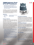
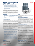
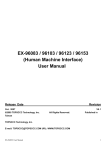
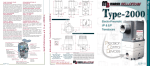
Type 2000
I/P & E/P Transducers
Description
The Marsh Bellofram Type 2000 is a robust
electronic instrument that regulates an incoming supply pressure down to a precise output
pressure which is directly proportional to an
electrical control signal. The secret to the Type
2000’s precise, reliable performance under a
variety of demanding environmental conditions
is a patented piezo-ceramic actuator with many
industry-wide firsts.
The Type 2000 has been designed to meet the
electro-pneumatic needs of the world:
• Field-selectable inputs and direct/reverse/
split ranging
• Multiple input/output/mounting
configurations
• Precise, reliable performance under extreme
conditions of temperature, vibration, orientation, supply pressure changes, supply voltage
changes, RFI/EMI, humid / oil-laden media,
and corrosive surroundings
Applications
The Type 2000’s precisely regulated pneumatic
output can be used to operate:
Transducers
• Valve Actuators
• Louver and Damper Actuators
• Valve Positioners
• Relays
• Clutches and Brakes
• Controllers
• Air Cylinders
Industry Applications Include
• Chemical and Petrochemical Industries
• Petroleum Production
• Pipeline Transmission
• Electric Utilities
• Water and Wastewater Systems
• Pulp and Paper
• Textiles
• Semiconductor Industry
• Food and Beverage
• Environmental Control Systems
• Construction Equipment
• Agricultural Equipment
• Machine Tool
• Material Handling
• Automotive Testing and Assembly
• Medical Equipment
72
Principle of Operation
The Type 2000 I/P and E/P transducers utilize
closed-loop pressure feedback-control for precision
pressure output and minimized effects of temperature, supply pressure changes, supply voltage
changes, and mounting angle.
Supply pressure is reduced by the supply valve
to provide an output pressure which is internally
routed to a precision temperature compensated
piezo-resistive pressure sensor. Supply pressure
is also routed to an externally removable orifice
which provides a reduced pilot pressure to a
chamber containing a servo diaphragm and nozzle.
Pilot pressure is controlled by modulating the gap
between the face of a nozzle and an adjacent
piezo-ceramic actuator, which is part of a unique
patented mechanism.
The piezo-ceramic actuator serves as a control link
between electrical input and pressure output as
follows:
• The input current (I/P) or voltage (E/P) signal
is conditioned to provide a normalized control
signal directly proportional to the desired pressure
output.
• Simultaneously the output of the pressure sensor
is amplified and conditioned to produce a feedback
signal.
• The sum of the control signal and the feedback signal produce a command signal which is delivered
as a DC voltage to the piezo-ceramic actuator.
• As voltage increases, the force applied by the
actuator increases, so as to restrict nozzle bleed
and thus increase pilot pressure.
• Increased pilot pressure applied to the servo
diaphragm directly causes opening of the supply
valve and an increase in the output pressure until
the output feedback signal and control signal
combine to produce the correct command signal.
Fine-Tuning Your Application
For optimal performance in your application, the
calibration of the Type 2000 can be fine-tuned
in the field. An easily-removable cover provides
access to the isolated electronics. All potentiometers, connections, jumpers, and switches
are clearly marked on the circuit board or on the
handy chart located on the inside of the cover.
The three elements of calibration (Gain, Zero, and
Span) are described below. Consult the Type 2000
User’s Manual for detailed calibration procedures,
cautions, and instrumentation requirements.
Gain (Damping) Adjustment
The output response of the Type 2000 can be
optimized for varying downstream volumes by
adjusting the system gain of the control circuit.
Adjust the Gain Pot counterclockwise for increased
gain; clockwise for increased oscillation damping.
For maximum allowable gain in your application,
the pot should be turned clockwise until oscillation just disappears.
Type 2000
Transducers
Note
The combined adjustments of Gain, Zero and
Span are all interactive. It may take several
adjustment attempts to accomplish final desired
setting.
Zero and Span Adjustments
The Type 2000 contains multi-turn Coarse-Zero,
Fine-Zero, and Span adjustment potentiometers
which are clockwise positive. Adjustment of
either Zero Pot changes the unit’s minimum output while the Span Pot changes the maximum
output.
Wide Rangeability
The Type 2000 can be field calibrated to pressure ranges other than the standard ones by
combinations of recalibration, pressure range
switching, and split high/low ranging. A unit
should not be switched to a range outside its
pressure sensor family (eg., a 0-15 PSIG can be
switched to a 3-15 PSIG, but not to 0-30 PSIG).
(Caution: Do not exceed the range of the onboard pressure sensor.) For example, the easiest
way to recalibrate a 0-30 PSIG unit to 3-15 psig
would be to change the switch setting to 3-27
PSIG, then switch to split range low.
Field-Selectable Features
Onboard switches allow the user to easily reconfigure the Type 2000 for any of several electrical
inputs, direct/reverse acting, or output split-ranging high/low. Fine tuning of the unit’s calibration
may be necessary after a reconfiguration.
800.727.5646 • www.marshbellofram.com
Direct/Reverse Acting
Split Ranging (High or Low)
Direct Acting transducers regulate to their minimum output when supplied
with minimum input; maximum out with maximum in. Reverse Acting
transducers regulate to their maximum output at minimum input.
The Type 2000 can be configured to regulate either half (top or bottom)
of its normal output range, when supplied with its normal full-ranging
electrical input. For example, a 0-10V 0-30 PSI unit set to split range low
will regulate 0-15 PSI @ 0-10V. It will regulate 15-30 PSI @ 0-10V if set to
split range high.
Electrical Port Options
1) 1/2 NPT Conduit
2) 20mm Conduit
3) Hirschmann® (DIN 43 650-A)
4) Terminal Block
Easy Access Top Cover
1) Isolated electronics
2) Calibration adjustments
3) Configuration switches
4) Switch information on
inside of cover
Easy Access Orifice
Mounting Options
1) In-Line
2) Direct: Holes on left
rear and bottom faces
3) Bracket Mounting options:
Panel, Pipe, Valve, DIN-Rail
Output Port
Same as Input Port
(Not shown; rear face)
Input Port Options
1) 1/4 NPT
2) 1/4 BSPP
3) 1/4 BSPT
Integral Booster
Flows up to 21 scfm for quick
system response
Manifold-Mounting Option
Supply and Output ports on the
bottom face rather than “through
the body”
Gauge Port
1/8 NPT on all models
(Not shown; rear face)
- Applies only to units ordered with approvals
Transducers
Agency Approvals
It is mandatory for the user to install a
suitably rated NRTL Listed or Certified conduit seal
Factory Mutual
E Model with F approval, Explosion Proof/Intrinsically Safe
Not for use with natural gas or other Non-inert Gases
Explosion Proof: Class I, Div 1, Groups A, B, C&D; T6, Ta = 60˚C
Dust-Ignition Proof: Classes II & III, Div 1, Groups E, F&G; T6, Ta = 60˚C
TYPE 4X, IP 66
Intrinsically Safe: Class I, II & III, Div 1, Groups A, B, C, D, E, F & G; T4, Ta = 60˚C;
TYPE 4X, IP 66
Non-Incendive: Class I, Div 2, Groups A, B, C & D; T4, Ta=60˚C
Suitable: Class II, Div 2, Groups F & G; T4, Ta = 60˚C
Suitable: Class III, Div 2; T4, Ta = 60˚C
Type 4X, IP 66
Entity Parameters:
I/P:
VMAX=30V,
IMAX=200 mA,
E/P: VMAX=30V,
IMAX=100 mA,
PMAX=1W,
PMAX=0.75 W,
Ci= 0, Li=0
Ci= 0, Li=0
E Model with G approval, Explosion Proof,
United States and Canada
For use with natural gas or other non-inert gases as a process
medium up to a maximum input pressure of 140 PSI when
installed with suitable NRTL listed, certified or approved conduit
seal installed at the enclosure.
Explosion Proof: Class I, Div 1, Groups A, B, C & D, T6 Ta = 60˚C
Dust-Ignition Proof: Classes II&III, Div 1, Groups E, F & G, T6 Ta = 60˚C
NEMA 4X, IP 66
S Model, Intrinsically Safe
Intrinsically Safe: Class I, II & III, Div 1,
Groups A, B, C, D, E, F & G, T4 Ta = 60˚C;
Non-Incendive: Class I, Div 2, Groups A, B, C & D, T4 Ta=60˚C
Suitable: Class II, Div 2, Groups F & G, T4 Ta=60˚C
Suitable: Class III, Div 2, T4 Ta=60˚C
Type 4X, IP 66
Entity Parameters:
I/P:
VMAX=30V,
IMAX=200 mA,
E/P:
VMAX=30V,
IMAX=100 mA,
PMAX=1W,
PMAX=0.75 W,
www.marshbellofram.com • 800.727.5646
Ci= 0, Li=0
Ci= 0, Li=0
S Model with Terminal Block, Intrinsically Safe
Intrinsically Safe: Class I, Div 1, Groups A, B, C, D; T4, Ta = 60˚C;
Non-Incendive: Class I, Div 2, Groups A, B, C & D; T4, Ta=60˚C
Entity Parameters:
I/P:
VMAX=30V,
IMAX=200 mA,
PMAX=1W,
Ci= 0, Li=0
E/P: VMAX=30V,
IMAX=100 mA,
PMAX=0.75 W,
Ci= 0, Li=0
CANADIAN STANDARD ASSOCIATION
E Model with F approval, Explosion Proof/Intrinsically
Safe, Certified to Two Standards.
Certified to CLASS 2258 04 PROCESS CONTROL EQUIPMENT
Class I, Div 1&2, Groups A, B, C, D; Class II, Div1, Groups E, F and G; Div 2,
Groups F and G; Class III.
Rated: 28Vdc, 8mA, T6; Enclosure TYPE 4X, IP66; Max Ambient Temperature 60˚C.
Entity Parameters:
I/P:
V =30V
IMAX=200mA
Li=0µH MAX
E/P: VMAX=30V
IMAX=100mA
PMAX=1.0W
Ci=0µF
PMAX=0.75W
Ci=0µF
Li=0µH
Certified to CLASS 2258 02 PROCESS CONTROL EQUIPMENT
Class I, Div 1 & 2, Groups A,B,C,D; Class II, Div 1, Groups E, F, G; Div 2, Groups F & G; Class III
Rated: 28Vdc, 8mA, T6; Enclosure TYPE 4X, IP66; Max Ambient Temperature 60˚C.
Entity Parameters:
I/P: VMAX=30V
IMAX=200mA
IMAX=100mA
E/P: VMAX=30V
PMAX=1.0W
PMAX=0.75W
Ci=0µF
Ci=0µF
Li=0µH
Li=0µH
ATEX (European Model)
INTRINSIC SAFETY: II 1 G EEx ia IIC T4 (-20<Ta<+60) EN 50014: 1997 (A2) EN
50020:1994 EN 500284: 1999
The Bellofram T-2000 Transducers were tested and found to comply with Electromagnetic
Compatibility Directive effective January 1, 1996. The relevant EMC specifications tested
were the following: EN 50081-1 (1992) and EN 50082-1 (1992). A Technical Construction File,
Serial #107 was written and Certificate of Conformity issued by a Competent Body.
73
Type 2000 Specifications
0.1% of full-scale output typical (0.25% guaranteed); includes effects of
hysteresis, dead band, and repeatability
Accuracy
Electrical
Inputs
Connections
Power Supply
Direct/Reverse Acting
Switch-Selectable
4-20mA. 0-5, 1-5, 1-9, 1-10, or 0-10VDC
1/2 NPT or 20mm Conduit
DIN Hirschmann (S model only)
External Terminal Block (S model only)
5-28VDC (with voltage inputs only)
Switch-Selectable
The secret to the Type 2000’s
precise, reliable performance
under a variety of demanding
environmental conditions
is a patented piezo-ceramic
actuator with many
industry-wide firsts.
Pneumatic
Outputs
Ports (Input/Output)
Exhaust
Ports (Gauge)
Supply
Split-Ranging
Consumption
Flow Capacity
Transducers
Exhaust Capacity
Stability
Supply Voltage Effect
Supply Pressure Effect
Vibration Effect
Mounting Position Effect
RFI/EMI
Temperature Effect
Storage Temperature
Approximate Weight
0-5, 0-15, 3-15, 1-17, 0-30, 6-30, 3-27, 0-60, 0-100, or 120 PSIG
0-0.1, 0-0.3, 0-1.0, 0.2-1.0, 0.07-1.2, 0-2.1, 0.4-2.1, 0.2-1.9,
0-4.1, 0-6.9, 0-8.3 BAR
1/4" (NPT, BSPT, or BSPP threads)
Bottom-ported for Manifold Mounting
(Explosion proof only) 1/8 - 27 NPT
1/8 NPT
For 0–5 PSIG (0.3 BAR) Through 0–60 PSIG
From 5 PSIG (0.3 BAR) above maximum output to 100 PSIG maximum
For 0-100 PSIG and 0–120 PSIG Ranges
From 5 PSIG (0.3 BAR) above maximum output to 140 PSIG maximum
Switch-Selectable, Full-Range or Split-Range High or Split-Range Low
4 SCFH maximum (1.9 LPM)
Range
Sensor
Flow
PSIG
BAR
PSIG
BAR
SCFM
LPM
0-5
0-0.3
5
0.3
11
312
0-15
0-1.0
15
1.0
15
423
3-15
0.2-1.0
15
1.0
15
423
1-17
0.07-1.2
15
1.0
15
423
0-30
0-2.1
30
2.1
15
423
3-27
0.2-1.9
30
2.1
15
423
6-30
0.4-2.1
30
2.1
15
423
0-60
0-4.1
50
3.5
17
480
(Typical Flow @ 100 PSIG (6.9 BAR) in and maximum out)
0-100
0-6.9
100
6.9
21
595
0-120
0-8.3
100
6.9
21
595
(Typical Flow @ 140 PSIG (9.7 BAR) in and maximum out)
3 SCFM (85 LPM) @ 5 PSIG (0.3 BAR) above setpoint
(0-15 PSIG range unit set at mid range)
PSIG BAR
70 4.8
140 psig supply pressure
regulated Pressure
60 4.1
50 3.4
40 2.8
30 2.1
20 1.4
10 0.7
0 0
SCFM 0
LPM 0
74
2
57
4
6
8
113 170 227
Instrument-quality air consists of:
a. A dew point less than 35º F
b. No particles larger than three microns
c. Maximum oil content of 1 ppm
None
None
<1% FS (+/-1G; 5-1000Hz)
None
CE-Compliant
0.02% FS/˚F (-40˚ to 180˚F [-40˚ to 82˚C])
-40˚to 200˚F (-40 to 93˚C)
3.0 lbs, 1.35 kg
TYPE 2000: REGULATED PRESSURE VS. FLOW
10 12 14 16
18 20 22 24
283 340 397 453 510 566 623 680
High Flow
Med Flow
Low Flow
Forward Flow
Air Quality
It is mandatory for the user to
install a suitably rated NRTL
Listed or Certified conduit seal
Type 2000 Mounting Options
Mounting Method
In-Line
Direct Mounting
Panel Bracket
Valve Bracket
Pipe Bracket
DIN-Rail Bracket
Manifold Plate
Intrinsically-Safe (S) Model
Yes
Side or Bottom Holes
Supplied
Accessory
Accessory
Accessory
Accessory
Explosion-Proof (E) Model
Yes
Side or Bottom Holes
Accessory
Supplied
Accessory
Accessory
Accessory
Mounting: The Type 2000 can be mounted in-line, or directly to a panel via mounting
holes located in the side and bottom of the unit. In addition, the S model includes a panelmounting bracket; while the E model includes a valve-mounting bracket. Kits are available
for mounting of either model to panel, valve, pipe, or DIN-Rail. A custom plate is available
for mounting of the bottom-ported version to a manifold. (See Accessories)
800.727.5646 • www.marshbellofram.com
Type 2000 Ordering Information
Type 2000 Accessories
2 K
Part Number
Enclosure
Panel Mounting Kit
010-135-000
Valve Mounting Kit
010-134-000
2" Pipe Mounting Kit
(Valve Mounting Kit is required)
010-143-000
DIN Rail Adapter
010-115-000
Pneumatic Ports
Manifold Adapter Kit
NPT
BSPT
BSPP
Manifold Mount3
Filter Kit, 60 microns
971-158-000
010-139-000
Pressure Gauge Kit
15 PSIG (1 BAR)
010-138-000
Pressure Gauge Kit
30 PSIG (2.1 BAR)
010-138-001
Pressure Gauge Kit
60 PSIG (4.1 BAR)
010-138-002
Pressure Gauge Kit
160 PSIG (11 BAR)
010-138-003
Intrinsically Safe
Explosion Proof
Electrical Port1
N
M
H
T
1/2 NPT Conduit
20mm Conduit ”S” Unit Only
Hirschmann5
Terminal Block2 ”S” Unit Only
N
T
P
M
Agency Approval
6
F
C
FM/CSA
ATEX ”S” Unit Only
FM Natural Gas Approved
for US and Canada4
G
Electrical Input
42
05
15
19
11
01
4-20 mA
0-5 V
1-5 V
1-9 V
1-10 V
0-10 V
Type 2000 Notes
1
Mode
D
R
Direct Acting
Reverse Acting
Full Range
Split Range High
Split Range Low
Pneumatic Output
005
015
315
117
030
630
327
060
0-5 PSIG
0-15 PSIG
3-15 PSIG
1-17 PSIG
0-30 PSIG
6-30 PSIG
3-27 PSIG
0-60 PSIG
0-0.3 BAR
0-1.0 BAR
0.2-1.0 BAR
0.07-1.2 BAR
0-2.1 BAR
0.4-2.1 BAR
0.2-1.9 BAR
0-4.1 BAR
100
120
0-100 PSIG
0-6.9 BAR
0-120 PSIG
0-8.3 BAR
Maximum Supply for
these regulators is
100 PSIG
Maximum Supply for
these regulators is
140 PSIG
It is mandatory for the user to install a
suitably rated NRTL Listed or Certified conduit seal
Type 2000 Wiring Connections and Switch Positions
Switch #
1: PSIG
BAR
2
3
4
ON
Switch #
1: PSIG
0-60
0-120
Yes
Yes
No
No
NEMA 4X / IP66 not available
Bottom O-Ring Ports
4
NRTL listed or certified conduit seal installed by user
5
Not Agency Approved
F
C
G
6
Agency Approval
FM/CSA ATEX Gas
S Intrinsic
Yes
Yes
No
Safety
Enclosure
E Explosion
Yes
No
Yes
Proof
3
00 None
0-1.0
0.2-1.0
0.07-1.2
0-2.1
0.2-1.9
0.4-2.1
0-6.9
Yes
Yes
Yes
Yes
2
Special
0-15
3-15
1-17
0-30
3-27
6-30
0-100
N
M
H
T
Electrical Port
Mode
F
H
L
OFF
Enclosure
S
E
Availability
Terminal Block I/P Transducer E/P Transducer
S
N/C
+ Signal
+
+ Signal
+ Power Supply
-
- Signal
Common
5
6: psig
BAR
7
8
9
0-1.0
0.07-1.2
0-2.1
0-4.1
0-6.9
0-8.3
Reverse
Acting
Full
I/P
1-5 VDC
0-5 VDC
Split Low
Voltage
Input
(E/P)
Split Low
Full
0-15
1-17
0-30
0-60
0-100
0-120
BAR
2
3
4
5
6: psig
BAR
7
8
9
0-4.1
0-8.3
1-9 VDC
0-10 VDC
4-20 mA
Split High
3-15
3-27
6-30
0.2-1.0
0.2-1.9
0.4-2.1
Direct
Acting
Split Low
Split High
E/P
www.marshbellofram.com • 800.727.5646
Full
Split High
Current
Input (I/P)
Transducers
S
E
75
Type 2000 Dimensions
1/2-14 NPT
.716
2X M3X0.5
X .250 DEEP
2X 8-32 UNC-2B
X .375 DEEP
MOUNTING HOLES
4.780
.360
3.883
OUT
1.893
IN
.570 TYP
.550
1.060
1/4-18 NPT TYP
Marsh
Bellofram
1.100
Type 2000 Explosion Proof Dimensions
2.307
1.37
[34.7]
2.225
Transducers
2.939
3.92
1.10
[99.5]
[27.9]
0.55
[14.0]
6.01
[152.6]
2.06
1.78
OUT
[52.3]
[45.2]
0.68
[17.3]
Drawings and dimensions are for reference only.
2.12
0.57
[14.5]
[53.8]
76
800.727.5646 • www.marshbellofram.com


![RC400G Residual Chlorine Analyzer [Style: S3]](http://vs1.manualzilla.com/store/data/005893183_1-484cd185856d4428f9cc01b01a19e45f-150x150.png)