1
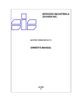
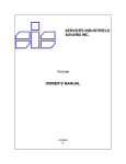
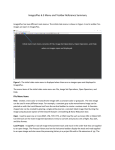
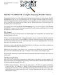
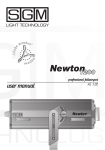
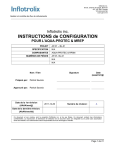
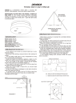
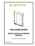
PROLIFT SCL / PROLIFT VOYAGER
Accessibility Lifts
OWNER’S MANUAL
(To Be Retained by Owner After Installation by Authorized Savaria Concord Dealer)
©Savaria Concord Lifts Inc.
Part # 000585 (Rev. 05-06-1)
IMPORTANT
The Prolift SCL or Prolift Voyager must be installed, maintained and serviced by
an authorized SAVARIA CONCORD DEALER only! Under no circumstances is
anyone other than a trained and authorized Savaria Concord Dealer to install,
adjust, service or modify any mechanical or electrical device on this lift.
Failure to follow this warning can result in safety systems being compromised
or defeated, which can result in serious injury or death. Savaria Concord Inc.
accepts no liability for property damage, warranty claims or personal injury,
including death, in this circumstance.
Lift and elevator passenger safety is the result of countless details in the
equipment’s design, manufacture and installation. After installation, reliable
operation and continued assurance of safe operation requires regular service
and inspection to be carried out at least twice per year, or more frequently
where usage or environment dictates or as required by local jurisdiction. The
owner is responsible to ensure that regular service and inspections occur in a
timely manner.
The owner must refer to this manual for operating instructions and precautions
for usage of this Prolift SCL or Prolift Voyager.
On completion of installation, the dealer must provide the owner with the
information below and ensure it is recorded in the owner’s manual. Any service
and/or maintenance must also be recorded in the Maintenance Record section
of this manual by the authorized Savaria Concord Dealer or the owner.
WARRANTY
Your Savaria Concord Dealer will provide a copy of the manufacturer’s limited
product warranty and documentation relating to any labour warranty offered
by your Dealer.
FOR OWNER’S RECORDS
Installing
Dealer:
Installing
Dealer:
Dealer’s Telephone Number:
Date Installed:
Serial Number:
Lift Model:
Comments:
2 of 16
PROLIFT SCL /PROLIFT VOYAGER
ACCESSIBILITY LIFTS
OWNER’S MANUAL
TABLE OF CONTENTS
1.
GENERAL SPECIFICATIONS
4
2.
STANDARD FEATURES
6
3.
OPTIONAL FEATURES
8
4.
OPERATING THE ELEVATOR FROM THE LANDING CONTROLS
9
5.
OPERATING THE ELEVATOR FROM THE CAB CONTROLS
11
6.
POWER FAILURE AND EMERGENCY LOWERING
12
7.
EMERGENCY LIGHT
13
8.
MANUAL LOWERING DEVICE (MACHINE ROOM)
13
9.
EMERGENCY HANDS - FREE PHONE (OPTIONAL)
14
10.
MAINTENANCE AND INSPECTION CHECKS
15
11.
MAINTENANCE RECORD
16
THIS PRODUCT IS DESIGNED AND MANUFACTURED
TO EXACT SPECIFICATIONS. MODIFICATIONS OF THIS
PRODUCT IN ANY WAY CAN BE DANGEROUS AND
WILL VOID THE WARRANTY.
3 of 16
1.
GENERAL SPECIFICATIONS
PROLIFT SCL
Load Capacity
550 lbs. (250 kg), 750 lbs. (341 kg), 1000 lbs. (454 kg)
Rated Speed
30 feet per minute (0.15 m/s) (Nominal)
Power Supply
NOTE:
Amperage
may
vary
depending on individual units. Verify
requirements prior to installation of
power supply.
208 volt, three phase, 30 amps or
230 volt, single phase, 50 amps
Drive System
1:2 Cable Hydraulic
35” x 48” (889 mm x 1219 mm)
Cab Size
35” x 54” (889 mm x 1372 mm)
35” x 60” (889 mm x 1524 mm)
Maximum Travel
12 feet (1 m)
Maximum # of Stops
4 stops
Pit Depth Required
8” (203 mm) minimum up to 36” (914 mm)
Minimum Overhead
Clearance
92” (2337 mm)
Control System
Constant Pressure
Floor Selection
Magnetic Selector
Flooring Material
Plywood
Control Panel Finish
Stainless Steel
Hall Station Finish
Stainless Steel
Motor
3 HP (2.24 kW)
Cab Panel Finish
Standard Solid Melamine Panels
Lighting Supply
115 volt, 60 cycle, 15 amps
Clear Anodized Aluminum Cab Trim
Emergency Alarm and Stop Buttons with Emergency
Battery Back-up for Cab Lighting and Lowering
Standard Features
Four Recessed Incadescent Down Lights
Metal Push Buttons with Illuminated Haloes
Stainless Steel Handrail
White Egg Crate Ceiling
4 of 16
PROLIFT VOYAGER
Load Capacity
750 lbs. (341 kg), 1000 lbs. (454 kg), 1400 lbs. (635 kg)
Rated Speed
30 feet per minute (0.15 m/s) (Nominal)
Power Supply
NOTE:
Amperage
may
vary
depending on individual units. Verify
requirements prior to installation of
power supply.
208 volt, three phase, 30 amps or
230 volt, single phase, 50 amps (5 HP motor)
Drive System
1:2 Cable Hydraulic
47” x 60” (1194 mm x 1524 mm)
Cab Size
42” x 60” (1067 mm x 1524 mm)
35” x 84” (889 mm x 2134 mm, max. 1000 lbs load capacity)
Maximum Travel
36 feet (10.97 m)
Maximum # of Stops
5 stops
Pit Depth Required
14” (356 mm) minimum up to 24” (609 mm)
Minimum Overhead
Clearance
96” (2438 mm)
Control System
Constant Pressure or Single Automatic Push
Floor Selection
Magnetic Selector
Flooring Material
Plywood
Control Panel Finish
Stainless Steel
Hall Station Finish
Stainless Steel
Motor
3 HP (2.24 kW) or 5 HP (3.73 kW)
Cab Panel Finish
Standard Solid Melamine Panels
Lighting Supply
115 volt, 60 cycle, 15 amps
Automatic Timed in Car Lighting
“Car in Use” Illuminated Hall and Car Buttons
Digital Floor Indicator in Cab
Standard Features
Emergency Alarm and Stop Buttons with Emergency
Battery Back-up for Cab Lighting and Lowering
Four Recessed Incadescent Down Lights
Stainless Steel Handrail
White Egg Crate Ceiling
5 of 16
2.
STANDARD FEATURES
1)
Cab Key Switch (Figure 1-A)
The key switch turns the cab controls ON
and OFF. It is provided to limit the use of
the elevator to authorized persons only.
2)
Cab Operating Panel Buttons
(Figure 1-B)
Automatic Control
The Automatic Control Panel buttons
facilitate the UP/DOWN movement of the
cab between landings. Once the selected
landing button is pressed, the cab will
automatically move to the landing.
The cab will stop when the selected landing
is reached.
A
B
Constant Pressure Control
The Constant Pressure Control Panel
buttons facilitate the UP/DOWN movement
of the cab between landings. The selected
landing button must be pressed and held
until the cab moves to the landing. The cab
will stop when the button is released or
when the selected landing is reached.
3)
D
E
Door Open Button (Figure 1-C)
The elevator door/gate will close
automatically after a pre-set adjustable
time of 8 seconds. This button can be
pressed to open the door/gate when the
cab is at a landing.
4)
C
Figure 1
3 Stop COP Panel
Emergency Stop Button (Figure 1-E)
The button can be set to Stop at any time to stop the cab and activate
the alarm buzzer.
6 of 16
5)
Alarm Button (Figure 1-D)
The button can be pressed at any time to sound the alarm in case of an
emergency. If equipped with the Hands-Free Telephone, hold down the
button for approximately 3 to 10 seconds to activate the telephone line.
Refer to section 9 for more details.
6)
Handrail
A single handrail is mounted on the Cab Operating Panel side of the cab.
7)
Emergency Light
The COP emergency light remains ON in the event of a main power
failure. The emergency light uses a Battery Back-Up system with an
automatic recharger.
8)
Landing Hall Call Station Controls
(Figure 2)
Hall Call Stations are installed at all landings
to move the cab to the landing from which it is
being called. An optional key switch limits the
elevator’s use to authorized persons only.
9)
Landing Door and/or Gate Interlock
The Landing Door/Gate lock prevents the Figure 2 Hall Call Station
movement of the cab unless the door/gate is in
the closed and locked position. If the door/gate is not completely closed,
the cab will not move.
10)
Emergency Battery Operation
In the event of a building power failure, the door/gate system is provided
with an temporary power back up system to continue the opening
operation for a number of times. On resuming normal building power, the
back up system will turn OFF and begin automatic recharging.
7 of 16
3.
OPTIONAL FEATURES
Automatic Door Opener
a)
Press the Landing Hall Call button to call the elevator. The entrance
door will open automatically once the elevator stops at the landing.
b)
Press the Remote Control (if equipped) to open the entrance door
once the elevator stops at the landing.
c)
Push ’n’ Go allows the entrance door to open automatically with a
slight push to the door itself. The door timer is inoperative when this
feature is activated.
Automatic Gate Opener
a)
Press the Landing Hall Call button to call the elevator. The Gate will
open automatically once the elevator stops at the landing and the
entrance door is fully open.
b)
Manually open the entrance door, the Gate will open automatically
once the entrance door is fully open.
NOTE
If the cab is equipped with a gate, the gate must be closed after
exiting the cab. If not, all controls will remain inoperable.
An “entry” and “exit” timer allows approximately nine seconds before
the hall buttons become operational. This delay allows time for a
person to enter/exit the cab.
8 of 16
4.
OPERATING
CONTROLS
THE
ELEVATOR
FROM
THE
LANDING
Automatic Operation
1)
Insert the key (if equipped) into the switch on the Hall Call and turn
the key to the ON position.
2)
Press the Hall Call button once and release. The elevator will
automatically come to your landing.
3)
Turn the key (if equipped) to the OFF position and remove the key.
4)
If required, turn the door handle and pull the door open.
5)
If the cab is equipped with a manual gate, slide the gate open and
enter the cab.
6)
Once inside the cab, close the gate, insert the key (if equipped)
into the key switch, and turn the key to the ON position.
NOTE
When using the landing controls, the cab can only be moved (called)
to the level from which you are calling. When using the control
buttons in the cab, the cab can be moved to any level.
WHEELCHAIR WHEELS MUST BE LOCKED AT ALL
TIMES WHEN THE ELEVATOR IS MOVING
9 of 16
Constant Pressure Operation
1)
Insert the key (if equipped) into the switch on the Hall Call and
turn the key to the ON position.
2)
Press and maintain constant pressure on the Hall Call button until
the cab stops at your landing. To stop the cab at any point simply
release the Hall Call button.
3)
Turn the key (if equipped) to the OFF position and remove the key.
4)
If required, turn the door handle and pull the door open.
5)
If the cab is equipped with a manual gate, slide the gate open and
enter the cab. Once inside the cab, close the gate, insert the key (if
equipped) into the key switch, and turn the key to the ON position.
If the elevator is equipped with our Automatic Pro-Door follow this
procedure:
a)
Stay clear the swing of the landing door. The door will “chime” and
then swing open automatically. If cab is equipped with an automatic
gate, the gate will open at this time. The door and gate are timed to
stay open for a few seconds. Enter the cab. Once inside the cab,
lock wheelchair wheels.
If the elevator is equipped with our Manual Pro-Door follow this
procedure:
b)
Pull on the door handle and open the landing door. If the cab is
equipped with a gate, slide the gate open at this time and enter the
cab. Once inside the cab, close the landing door and then the gate.
Lock wheelchair wheels.
10 of 16
5.
OPERATING THE ELEVATOR FROM THE CAB CONTROLS
Automatic Operation
1)
Insert the key (if equipped) into the switch located in the Cab
Operating Panel. Turn the key to the ON position.
2)
Press the selected Landing button once and release. The elevator
will automatically travel to and stop at the selected landing.
3)
Turn the key (if equipped) to the OFF position and remove the key.
4)
Unlock the wheelchair wheels and exit the cab (if applicable).
Constant Pressure
1)
Insert the key (if equipped) into the switch located in the Cab
Operating Panel. Turn the key to the ON position.
2)
Press and maintain constant pressure on the selected Landing
button to move the elevator. Maintain constant pressure until the
elevator automatically stops at the desired landing. To stop the
elevator at any point simply release the Hall Call button.
3)
Release the Landing button when the elevator arrives at the
landing.
4)
Turn the key (if equipped) to the OFF position and remove the key.
5)
Unlock the wheelchair wheels and exit the cab (if applicable).
If the elevator is equipped with our Automatic Pro-Door follow this
procedure:
a)
The gate will open and the door will “chime” and then swing open
automatically. The door and gate are timed to stay open for a few
seconds. Exit the cab. The gate and door will close.
If the elevator is equipped with our Manual Pro-Door follow this
procedure:
b)
If cab is equipped with a gate, slide the gate open at this time and
then open the manual swing landing door. Exit the cab. Close the
gate and then the landing door.
11 of 16
6.
POWER FAILURE AND EMERGENCY LOWERING
In the event of a power failure, the elevator is equipped with a Battery
Back-Up system that allows the user to lower the elevator from the inside
of the cab. This device operates on batteries and is only activated if a
main power supply failure occurs. The operation is as follows:
1)
a)
For elevators with automatic operation, press any
Landing button below the floor where the elevator is located.
b)
For elevators with constant pressure operation, press
any Landing button below the floor where the elevator is
located and maintain constant pressure until the cab is level
with the lower landing.
2)
On arrival at the selected floor, the landing door will automatically
unlock.
3)
If the door is equipped with an automatic gate, the gate will open.
4)
Release the button, remove the key, open the manual gate (if
equipped) and exit the cab.
12 of 16
7.
EMERGENCY LIGHT
In the event of a main power failure, the emergency cab light will light
automatically.
8.
MANUAL LOWERING DEVICE (MACHINE ROOM)
In the event of power failure, the cab can be moved to a lower level
manually by using the following procedures:
1)
Obtain the key to unlock the door to the machine room where the
elevator pump unit is located (if applicable).
2)
Instruct the person(s) in the elevator to remain calm and stay well
back from the door of the elevator. Ease their concern by telling
them your intentions.
3)
Switch
the
main
disconnect switch for the
main power supply to the
elevator pump unit to the
“OFF” position
4)
If equipped, use the
owner’s key to unlock
the Controller Tank
cover. The EPV Valve is
located inside.
5)
Manual Lowering Knob
(pull to lower lift)
Locate the red manual
Figure 3 EPV Valve
release knob on the EPV
Valve and pull the knob
to lower the cab (refer to Figure 3). Maintain a constant pull on
the knob until the elevator reaches the lowest landing and stops
automatically. (Although you may not be able to see the elevator,
this is readily detected, as there will be no further noise as the oil
flows to the reservoir).
13 of 16
6)
To exit the cab, open the lower landing door and assist the
passenger(s).
7)
After passenger(s) have exited the cab, remove the cab key. Make
sure the landing door is closed, reconnect the disconnect switch in
the machine room and lock the door.
9.
EMERGENCY HANDS - FREE PHONE (OPTIONAL)
1)
If your lift is equipped with an Emergency Hands-Free Telephone,
press and hold down the Alarm button to activate the phone line. A
short time delay (adjustable by the installing technician) will occur.
2)
Release the Alarm button once the call is picked up by the
telephone line.
The system will automatically dial out to a pre-programmed telephone
number as set up by the installing technician
14 of 16
10.
MAINTENANCE AND INSPECTION CHECKS
Regular maintenance will keep your elevator in proper operating condition.
Please remember, as the owner of this elevator, you are responsible
for making sure that maintenance and upkeep are done on a regularly
scheduled basis. To ensure proper operating condition of your unit, the
items listed below must be inspected and, if necessary, serviced a minimum
of twice per year. Additional inspections may be required depending on
usage.
1)
Tighten all rail and cab fastening bolts.
2)
Lubricate the door hinges and adjust the door closure if required.
3)
Lubricate the rails with light grease, such as white lithium.
4)
Inspect the travelling cable for wear. Replace if any cuts or damage
to the jacket are evident.
5)
Check for any hose/pipe leaks. Replace and/or tighten the fittings to
correct any hydraulic leaks found.
6)
Check the fluid level of the pump reservoir (with the elevator at its
lowest landing), and fill as required. (Use Grade 32 Hydraulic Oil).
There must be at least 1” inch of oil on the dipstick.
7)
Tighten any hose connections or bleeder valves found loose. Check
the hydraulic cylinder (jack) for any leaks. If necessary, the packing
seals may have to be replaced.
8)
Replace the batteries inside the control panel as indicated on the
battery label.
9)
To perform the required maintenance to the Kwiklock or Pro-lock (if
equipped), call your Authorized Savaria Concord Dealer.
10)
Activate and test the safety mechanism.
UNDER NO CIRCUMSTANCES SHOULD THE PUMP
CONTROLS OR VALVE SETTINGS BE ADJUSTED
EXCEPT BY AN AUTHORIZED CONCORD DEALER
15 of 16
11.
MAINTENANCE RECORD
It is recommended that the Owner update the Maintenance Record after each service
call.
Date
Time
Reason for Call
Comments
16 of 16
Dealer