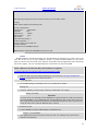
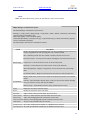
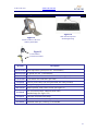
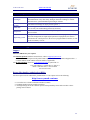
1
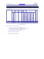
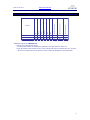
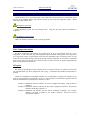
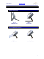
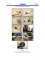
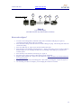
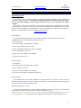
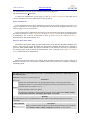
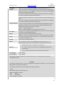
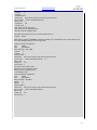
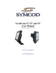
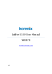
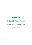
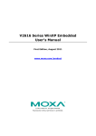
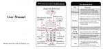
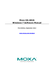
TermiCom SE-15 X7 User Manual Documentation Version : 19-03-2012 WEB site: www.symcod.com E-mail: [email protected] TermiCom SE-15 X7 Warranty Symcod warrants its products to be free from defects in material and workmanship during one year from the purchase date. If a product proves to be defective in material or workmanship during the warranty period, Symcod will, at its choice, repair or replace the product with a similar product. Replacement Product or parts may include remanufactured or refurbished parts or components. The replacement unit will be covered by the balance of the time remaining on the customer's original limited warranty. Symcod provides no warranty for the third-party software included with the product or installed by the reseller, distributor, customer or any other party. Warranty does not include: Any product, on which the serial number has been defaced, modified or removed. Damage, deterioration or malfunction resulting from: Accident, misuse, neglect, fire, water (except for waterproof units), lightning, or other acts of nature, unauthorized product modification, or failure to follow instructions supplied with the product. Repair or attempted repair by anyone not authorized by Symcod. Damage to or loss of any programs, data or removable storage media. Software or data loss occurring during repair or replacement. Any damage of the product due to installation of the product. Causes external to the product, such as electric power fluctuations or failure. Use of supplies or parts not meeting Symcod specifications. Failure of owner to perform periodic product maintenance as stated in documents supplied. Any other cause which does not relate to a product defect. Damage caused by static. Removal, installation, freight and set-up service charges. WWW.SYMCOD.COM Warning Safety & reliability, page 3 Cleaning, pages 4 & 20 Powering, page 7 Earth ground, page 7 Fixation & handling, pages 9 & 10 Sealing, pages 12 & 13 Oxidation, page 16 Disclaimer The material on this document* is intended for end user, distributor and/or reseller use. Although downloading and printing documents is allowed, Symcod will not be responsible for any modification or any other use of any content in the displayed/downloaded material. Please note that all documents* are subject to change without notice and are occasionally revised to specify, correct or revise the content or for other purposes. Therefore, the version displayed on the site may differ from your original printed copy. Please contact us if you require assistance. Symcod Inc. assumes no liability for damage incurred directly or indirectly, errors, omissions or discrepancies between the device and the manuals or documents supplied. Symcod is not responsible for any loss or damage (Including data corruption, interruption of operation, lost business information, lost production, etc.) caused by use, non-use or misuse of any of the information contained in this document*. Symcod Inc is not responsible of the content or validity of the links gave as references for other products not manufactured by Symcod Inc. *Documents include instruction book, user guide, operating instructions, manuals, safety precautions / instructions, data sheets or any other documents supplied by Symcod. 2 TermiCom SE-15 X7 WWW.SYMCOD.COM IMPORTANT Read me first By carrying out the installation and the use of this equipment you accept the rules and limitations described in this document or any other document relating to this product. By carrying out the installation and the use of this equipment you are presumed having read all the safety warnings ( ). WARNING: Safety and reliability SYMCOD Inc will not be responsible for the use of this equipment for other purpose then data collection. This equipment is designed and intended for an industrial and commercial use only. The TermiCom SE-15 X7 is not for a residential use. 3 TermiCom SE-15 X7 WWW.SYMCOD.COM TermiCom SE-15 X7 TermiCom SE-15 X7 is a robust sealed computer specially designed for industrial and manufacturing use. The Stainless steel casing enables the SE-15 X7 to function even in the most hostile environments. TermiCom SE-15 X7 is dust resistant and can be the subject of direct watering (see cleaning). It is frequently used in industries where the hygiene standards require equipment cleaning and/or sterilization. Basic TermiCom SE-15 X7 is provided with a Intel Atom 1,6 GHz processor, a 15" tactile color screen (LCD TFT resistive) and with a solid stainless steel stand which allows desktop or wall mount installation in a few minutes. Several inputs and outputs make possible the addition of peripherals such as industrial keyboard, bar code scanner or any other peripheral. The flash disk included with the basic version can be completely write-protected. This feature is used to prevent any modification made by the user that could put in danger the application or the operating system. The basic operating system included in TermiCom SE-15 X7 is Windows Embedded Standard 7; it is directly installed on the flash disk. The Ultra-Resistant touch screen is used in environment in which there is particularly abrasive dust. Contrary to the standard touch screens that are covered with a polymer, this one is covered with a thin layer of tempered glass, which makes it much more resistant to the abrasives and even allows it to function with deep scratches. Several options are available in order to adapt TermiCom SE-15 X7 to specific needs. TermiCom SE-15 X7 provided with the wide temperature option allows the operation of TermiCom SE-15 X7 at below zero temperature. You can also use the wireless version of TermiCom SE-15 X7 by including the WiFi 802.11b option. According to your needs, a keyboard shelf with variable slope can be added to your TermiCom. WARNING: cleaning Stainless steel may react to some chemical agents, particularly with chlorine (Ci) component. Check with your cleaning product supplier to ensure that the products used for cleaning are suitable and that they will not damage the stainless steel case. 4 TermiCom SE-15 X7 WWW.SYMCOD.COM Main characteristics X X X X 1 1 4 4 2 2 0 0 0 0 0 0 O O 37W 37W Storage Hard Disk (min. 80Gig) 1 Maximum power consumption (without peripheral nor Wide Temperature option) X X Keyboard shelf 2 32Gig Flash Disk (SSD) X X SVGA port 2Gig DDR2 O O Audio output Windows Embedded Standard 7 X X Parallel port 15" Ultra resistant - Resistive 004-01574B-5200 Ethernet Product # 004-01573B-5200 Serial port RAM USB port Operating System Comm. 1Gbit Ethernet port Color Touch screen LCD 802.11B TermiCom SE-15 X7 Inputs / Outputs O = Available Option * Basic characteristics, TermiCom SE-15 X7: o o o o Sealed case, stainless steel 304 #4 (see cleaning page 5). 15in LCD 24 bits LCD (1024 X 768), color, resistive touch screen Intel Atom 1,6 GHz processor, low power consumption Stainless steel stand, wall mount or desktop use 1 Wireless RF 802.11B option available 2 Basic model without keyboard shelf 5 TermiCom SE-15 X7 WWW.SYMCOD.COM Inside Outside Dust Water Minimum Temperature Maximum Temperature Relative Humidity % 1 Environmental specifications T ermiCom SE-15 X7 X X X X X 5°C 40°C 100 With Wide T emperature option X X X X X -30°C 40°C 100 With RF option X X X X X 5°C 40°C 100 1 Mobile Fix Product Maximum temperature, IMPORTANT: * Do not cover while the unit is ON. * The back of the TermiCom should not be placed flat on a table while the unit is ON. * Keep the surfaces of the TermiCom free of any material and respect a minimum area of 2” between the back of TermiCom and of any surface in order to allow the dissipation of the internal heat 6 TermiCom SE-15 X7 WWW.SYMCOD.COM Power TermiCom SE-15 X7 is powered through a 12ft sealed cable which connects to a 120/240VAC power network for the standard models, and 120VAC network for units with wide temperature option. (Power cable is provided with the unit) WARNING: powering Before installation, please turn off powering source. completed. Plug the unit only when the installation is WARNING: earth ground Make sure that the TermiCom casing is properly grounded. Options description Wide Temperature option The Wide Temperature option allows the TermiCom SE-15 X7 to be functional down to a -30°C temperature. If your TermiCom with wide temperature option remained without power at low temperature for a long period of time, it is possible that it does not start immediately when you turn the power on. The TermiCom will not allow starting as long as the internal operation temperature is not reached. The internal power (120V) must be in function for a certain time laps in order to increase the internal temperature that allows the electronic parts to function. RF option RF option (# OPT-RFSE15) makes possible the use of TermiCom SE-15 X7 without network cable. The communication type Wi-Fi supports the 802.11a/b/g. A minimum 802.11B Wi-Fi infrastructure is required. NOTE: For installations with multiple antennas, it is recommended to configure the antennas (access point) on various channels, like channels 1, 6 and 11. This will help avoid interferences problems that can result from antennas that are installed close from one an other. Example 1: Installation with two antennas, one will be configured at channel 1 and the other at channel 11. Example 2: Installation with three antennas, the first will be configured at channel 1, the second at channel 6 and the last at channel 11. Example 3: Installation with antennas, the first will be configured at channel 1, the second at channel 6, the third at channel 11, the fourth at channel 1 and the last will be configured at channel 6. 7 TermiCom SE-15 X7 WWW.SYMCOD.COM Using modes Desktop or wall mount Side view Wall mount version Side view Desktop version With or without keyboard shelf Side view With keyboard shelf Side view Without keyboard shelf 8 TermiCom SE-15 X7 WWW.SYMCOD.COM How to install your TermiCom SE-15 X7 The support provided with TermiCom SE-15 X7 permits to fix the unit on a wall or on a table. Once fixed, the angle of TermiCom SE-15 X7 can be easily adapted to the needs of each user, no loosen-tighten needed (see TermiCom fixation/handling). IMPORTANT: The TermiCom should not be cover while ON. The back of the TermiCom should not be placed flat on a table (or other surfaces), the back of the unit is acting as a heat dissipater. How to install TermiCom SE-15 X7 desktop position 1 Arms 3 Base 2 4 5 Pivot brackets Tightening button 1. Fix the base support on a horizontal surface, the open part of the base in front of the user. Be sure to choose a fixed and solid plane surface able to support the weight of the TermiCom. 2. 3. 4. 5. Firmly screw the arms to the base support. Tighten the nuts inside the base. Insert the pivot brackets in the arms. Firmly tight the tightening buttons to secure the fixation, place the TermiCom at the desired angle. WARNING: fixation & handling Choose a fixed and solid plane surface able to support the weight of the TermiCom (approximately 30 Pounds/13.6Kg). Handle the TermiCom safely in order to avoid any back wound. 9 TermiCom SE-15 X7 WWW.SYMCOD.COM How to install TermiCom SE-15 X7 wall mount position 2 1 Base Arm s 4 Pivot brackets 1. 3 5 Tightening button Fix the base support on a vertical surface, the open part of the base upwards. Be sure to choose a fixed and solid plane surface able to support the weight of theTermiCom. 2. 3. 4. 5. Firmly screw the arms to the base support. Tighten the nuts inside the base. Insert the pivot brackets in the arms. Firmly tight the tightening buttons to secure the fixation, place the TermiCom at the desired angle. WARNING: fixation & handling Choose a fixed and solid plane surface able to support the weight of the TermiCom (approximately 30 Pounds/13.6Kg). Handle the TermiCom safely in order to avoid any back wound. 10 TermiCom SE-15 X7 WWW.SYMCOD.COM Detailed Specifications TermiCom SE-15 X7 is provided with several ports allowing the connection of various types of peripherals according to needs, for example: printers electronic scales bar code scanners sensors etc. USB1 USB2 USB3 USB4 COM 1 Power supply ON/OFF Ethernet COM 2 Figure 1 TermiCom SE-15 X7 bottom view Power connector Figure 2 Power connector The power connector (figure 2) is used to plug the TermiCom SE-15 X7 to the 120V or 240VAC power system. A 12ft sealed cable is provided with the unit. 11 TermiCom SE-15 X7 WWW.SYMCOD.COM Ethernet connector Figure 3 Ethernet connector Figure 4 Ethernet connector cable TermiCom SE-15 X7 communicates through an Ethernet 1Gbit connection (figure 3). The sealed connector is an RJ-45 standard type. To ensure the sealing of the TermiCom (see sealing), you must install and use the Ethernet cable connector provided to complete the connection (see figure 4). If the Ethernet connector is not plugged, you must absolutely use the Ethernet connector cap provided (see figure 5) to ensure the sealing. As any Ethernet equipment that uses cable UTP Cat5, a maximum of 300 feet (91.44 meters) of cable is allowed between the "hub" and/or the "switch" and the TermiCom. For more details concerning wiring, please download the document "WIRING AND EXAMPLE OF CONFIGURATION TCPIP" available on www.symcod.com . Figure 5 Ethernet connector cap WARNING: Sealing You must use the recommended connectors to insure that the guarantee of sealing of TermiCom SE-15 X7 will apply. The connectors must be covered at any time by the special cable connector or by the recommended cap. 12 TermiCom SE-15 X7 WWW.SYMCOD.COM USB1,USB2, USB3 and USB4 connector Figure 6 USB connectors TermiCom SE-15 X7 has 4 USB connectors (see figure 6 # 1) which allow the connection of various USB peripherals. In order to ensure the sealing of TermiCom SE-15 X7 (see sealing), USB connectors must be covered at any time. If no peripheral is connected, the provided caps must be fixed. Two USB sealed adapters are also provided (see figure 8) and must be used in order to ensure the sealing of the USB peripherals connection. The adapters are designed for type A USB connections. See next page for the assembly procedure for USB adaptor. WARNING: Sealing You must use the recommended connectors to insure that the guarantee of sealing of TermiCom SE-15 X7 will apply. The connectors must be covered at any time by the special cable connector or by the recommended cap. 13 TermiCom SE-15 X7 WWW.SYMCOD.COM Assembly procedure for USB adaptors Figure 7 Important the USB connector must be type A (The provided connector can differ from the one showed) 14 TermiCom SE-15 X7 WWW.SYMCOD.COM A Part on the TermiCom B C D E Figure 8 Type A USB adaptor (Provided connector may differ from the one shown) Please refer to figure 7 1. 2. 3. 4. 5. 6. 7. 8. 9. To insure a full sealing (IP67), install the white sticker around the USB plug (B - figure 8), covering the four little holes of the over molding. Insert the black O Ring around the front face of the USB type A plug. This O Ring will ensure the connection sealing. Insert the USB cord (E - figure 8) set into the metallic back shell. Insert laterally to the cable the retention spacer (C - figure 8, this spacer is soft, in order to adapt to different shapes of over molding) and slide the over molding of the USB type A plug into this retention spacer. Insert laterally to the cable the friction ring (D - figure 8). Screw the part A (figure 8) on the USB connector of the TermiCom. Plug the USB connector (B – figure 8) in the TermiCom. Make sure that it is well inserted and in the required position. Complete the installation by assembling parts C-D-E and by screwing part A in part E (figure 8). The assembly procedure is complete, you can unplug the connector if needed. 15 TermiCom SE-15 X7 WWW.SYMCOD.COM Connectors COM1 and COM2 Figure 8 Serial port 1 and 2 TermiCom SE-15 X7 is provided with 2 serial port (8pins sealed, see figure 8). The serial ports allow the connection of peripherals such as printers, electronic scales and PLC. In order to avoid the oxidation of serial ports connector pins (see oxidation), the serial ports must be covered at any time. If no peripheral is connected, the serial port cap must be fixed. The cable used for the connection to the serial port his 8 pins male connector at one end and open at the other end (provided). You must connect the cable of your peripheral to the connector. See below for the cable pin-out (figure 10). 12345678- Power Out (optional) RX – Receive TX – Transmit DTR – Data Terminal Ready GND – Ground DSR – Data Set Ready RTS – Request To Send CTS – Clear To Send Figure 10 Connector pin out serial port 518-3E201B 8 pins male (included) WARNING: Oxidation You must use the provided connectors to avoid the oxidation of the serial port pins connectors. The connectors must be covered at any time by the special cable connector or by the provided cap. 16 TermiCom SE-15 X7 WWW.SYMCOD.COM Power switch Figure 11 Power switch The power switch (figure 11) allows turning on or off the TermiCom SE-15 X7. If your TermiCom was made with the wide temperature option and remained without power at low temperature for a long period of time, it is possible that it does not start immediately when you turned on the power. The TermiCom will not allow starting as a long as the internal operation temperature is reached. The internal power (120V) must be in function for a certain time laps in order to increase the internal temperature that allows the electronic parts to function. 17 TermiCom SE-15 X7 WWW.SYMCOD.COM TermiCom SE-15 X7 configuration Operating system The operating system of TermiCom SE-15 X7 is Windows Embedded Standard 7 (WES7) which is an embedded version of Windows 7. The Windows Embedded Standard 7 included in the TermiCom SE15 X7 is specifically designed to work with it and cannot in any case be transferred on another computer. This section covers some particularities of our WES7 operating system. Excluding that, the whole system operates as a Windows 7 system. If you don't find in this document the information you are looking for, please refer to the Microsoft documentation. If a specific configuration or application is working on a Windows 7 system and doesn't work on our WES7, please contact us: [email protected] System Restore A USB disk having the unique task of performing a restoration of the system in case of failure is integrated in the unit. To reinstall WES7 follow these steps: 1- Power on the unit 2- Enter BIOS setup by pressing "DEL" at startup 3- Enter "Advanced BIOS Features" menu 4- Select "Hard Disk Boot Priority" and press "ENTER" 5- Move "USB-HDD0" to priority 1 6- Press "F10" then "ENTER" to save and quit 7- Follow the steps on-screen After the Restore: 1- Reboot unit 2- Enter BIOS setup by pressing "DEL" at startup 3- Move "Ch0 M." to priority 1 4- Press "F10" then "ENTER" to save and quit 5- The system will complete its installation, please wait HyperTerminal The communication and terminal emulation tool HyperTerminal, since always offered with the Windows operating systems, is no longer available with version 7. As a replacement we installed TeraTerm v4.71 that can be accessed from the Start menu. Built-in Administrator account By default, the Administrator account is disabled in Windows 7 for security purpose. In the event that the use of this account would be essential it is possible to enable it that way: Access Control Panel, Administrative Tools, Computer Management. In the left pane open Local Users and Groups then select Users. In the right pane open Administrator and uncheck "Account is disabled" box. 18 TermiCom SE-15 X7 WWW.SYMCOD.COM The Administrator account will now be available from the Welcome Screen. The default password is Administrator. To disable the Administrator account again, go back to Computer Management and simply check "Account is disabled" box in the Administrator account properties. Run as Administrator Certain applications must be run as Administrator to be able to successfully complete every tasks. For a single or occasional use of such application, the right button of the mouse on the application's icon (or its shortcut) will give access to this function. Tu run an application as administrator all the time, use the right button of the mouse on the application's icon and select Properties. In the Compatibility tab, locate Privilege Level then check "Run this program as an administrator" box. If the box is unavailable to check, go in the Shortcut tab, click the Advanced… button and check "Run as administrator" box. Enhanced Write Filter (EWF) The Enhanced Write Filter (EWF) is a built-in functionality of the Windows Embedded Standard 7 that allows to write-protect the system. By default, this functionality is disabled. The EWF offers 3 methods of protection: EWF, HORM, FBWF. The different commands of each method of protection are explained in the following pages (from the Microsoft documentation). These commands can be run in a Command Prompt window and only as Administrator. EWF EWF protects the whole volume. Once enabled, all the modifications made to the system are effective in RAM only. When the system is restarted, everything is back to the previous state. The EWF is configured in RAM Reg mode. The EWF manager console application is used to control Enhanced Write Filter. EWF Manager uses the following syntax: EWFMGR <drive-letter>(optional) [options] Parameters drive-letter Specifies the volume path. This is an optional parameter that is used for protected volume configuration mode. To view the status of the protected volume, specify the drive letter for the protected volume, for example, ewfmgr c:. options Specifies the EWF volume boot options. The following commands are used to manage protected volume configuration: Disable, Enable, Commit, SetLevel, Restore, Checkpoint, Description, and Nocmd. Remarks The following table shows the Enhanced Write Filter (EWF) console manager application tool boot commands. Boot command All Description Displays information about all protected volumes and performs specified commands such as disable, enable, commit, checkpoint, and restore, on each volume. 19 TermiCom SE-15 X7 Checkpoint Commit WWW.SYMCOD.COM Starts a new overlay level. Same as SetLevel= [Current Overlay Level + 1]. Commits all current level data in the overlay to the protected volume, and resets the current overlay level to 1. The Commit command can be combined with the Disable command to commit and then disable. The overlay is written to the protected volume on the next system boot. Committing the overlay can impact the speed of the boot process. Commits all current level data in the overlay to the protected volume and disables the overlay. The overlay is written to the protected volume on the next system boot. Committing the overlay can impact the speed of the boot process. CommitandDisable You can use the -live command for both EWF RAM and EWF RAM Reg modes to immediately commit the overlay to the protected volume and disable the overlay without having to reboot the system. For example, Description Disable Enable ewfmgr c: -commitanddisable -live Note Live commit and disable is not supported for disk overlay. Allows the user to associate an ASCII string with an overlay level. This command can be combined with the SetLevel command. Disables the overlay on the specified protected volume. Enables the write filter so that data that is written to the protected media is cached in the overlays. The current overlay level becomes 1 as soon as EWF is started, and a new overlay is created at level 1. NoCmd Clears the current pending command. Restore Restores to the prior overlay. Same as SetLevel=[Current Overlay Level – 1]. Sets the current overlay level to the specified level. Valid values for levels are: SetLevel ActivateHorm DeactivateHorm [Current overlay level +1]. Starts a new overlay level. [0 - Current overlay level]. Sets the level, discarding all data above the specified level. [- Level]. Deletes all the data in the specified level and beyond. Enables HORM. Disables HORM. Because EWF manager commands are executed on the next boot, you must reboot the system for a command to take effect. Examples The following examples refer to a system on which EWF is configured to protect drive C, and on which the EWF partition resides on disk 1/partition 3. The following example shows how to check the EWF status and format: ewfmgr c: EWF manager displays the following result: Protected Volume Configuration Type DISK State DISABLED Boot Command NO_CMD 20 TermiCom SE-15 X7 WWW.SYMCOD.COM Param1 0 Param2 0 Persistent Data "" Volume ID D2 02 96 49 00 0E 59 96 02 00 00 00 00 00 00 00 Device Name "\Device\HarddiskVolume4" Max Levels 3 Clump Size 512 Current Level 1 Disk space used for data 0 bytes Disk space used for mapping 0 bytes Memory used for mapping 0 bytes The following example shows how to enable EWF for drive C. ewfmgr c: -enable EWF manager displays the Enable command as pending. The command does not execute until the next boot. EWF manager displays the following result: Protected Volume Configuration Type DISK State DISABLED Boot Command NO_CMD Param1 0 Param2 0 Persistent Data "" Volume ID D2 02 96 49 00 0E 59 96 02 00 00 00 00 00 00 00 Device Name "\Device\HarddiskVolume4" "C:\" Max Levels 3 Clump Size 512 Current Level 1 Disk space used for data 0 bytes Disk space used for mapping 0 bytes Memory used for mapping 0 bytes *** Enabling overlay Protected Volume Configuration Type DISK State DISABLED Boot Command ENABLE Param1 0 Param2 0 Persistent Data "" Volume ID D2 02 96 49 00 0E 59 96 02 00 00 00 00 00 00 00 Device Name "\Device\HarddiskVolume4" Max Levels 3 Clump Size 512 Current Level 1 21 TermiCom SE-15 X7 WWW.SYMCOD.COM The following example shows how to check the status type of the EWF volume. ewfmgr EWF manager displays the following result: Overlay Configuration Volume Size 2048030208 Segments 8192 Segment Size 249856 Free segments 8192 Max Levels 3 Max Protected Volumes 1 Protected Volumes 1 Overlay volume percent full 0.00 Protected volumes Arc Path "\Device\HarddiskVolume4" Note If EWF is disabled, the current level is shown as N/A HORM HORM (Hibernate Once/Resume Many) uses the hibernation file (hiberfile.sys) to always start in the same state. In the event of a system shutdown, whether it is planned (manual shutdown) or not (power failure), on the next boot the system will be identical. This method will also significantly reduce the boot up time of the computer. The size of the hibernation file created will be the same as the RAM. Enable a Hibernate Once/Resume Many Environment by Using EWF To enable a Hibernate Once/Resume Many environment that uses EWF 1. Make sure that your system supports hibernation. You can use the Powercfg Command-Line Options command line tool to enable hibernation. powercfg -h on 2. Use the EWF Manager command line tool to verify that EWF is enabled. Ewfmgr -all 3. If EWF is enabled, go to the next step. Otherwise, enable EWF. For example: ewfmgr -all -enable Important: You must use the -all command because HORM has a requirement that all volumes must either be protected with EWF or be in unmounted state when the Hibernate Once occurs. This is to prevent state synchronization problems. Each Resume from hibernation expects the entire system to be in exactly the same state as when the Hibernate Once occurred. 4. Restart the system. 5. Activate HORM by using the EWF Manager command line tool ewfmgr c: -activateHORM 6. Open applications and start any processes that you want to be running on the system when it resumes from hibernation. 22 TermiCom SE-15 X7 7. WWW.SYMCOD.COM Hibernate the system. shutdown /h 8. Restart the system. After you restart the system, EWF is enabled. In the event of an Autologin, when Windows is resuming from hibernation it may happen that the user is "locked". Selecting the user will start the session but there is a way to prevent this inconvenience and make the session start automatically as it is supposed to. To do this, access Control Panel, Power options. In the left pane, select "Require a password on wakeup" then select "Don't require a password". When the HORM is activated, changes that do not require to restart the system can be applied. Once changes are done simply re-hibernate. Disable EWF in a Hibernate Once/Resume Many Environment If you want to make changes or apply updates to your run-time image in a Hibernate Once/Resume Many (HORM) environment, you must first disable Enhanced Write Filter (EWF). Because the Boot Environment loads the hibernation file before it reads the pending EWF Manager start commands, you must disable EWF and load the system as usual. Because Hibernate Once/Resume Many environments are supported in EWF RAM and RAM Reg modes, you can use the ewfmgr -commitanddisable -live command which saves the runtime image from the EWF overlay to the persistent image on the system. In some cases, this is not desirable as it commits the whole cached image. To apply a specific set of changes to the system, you can disable EWF, disable HORM, apply changes, and re-enable HORM. To disable EWF in a Hibernate Once/Resume Many environment 1. Disable EWF by using the EWF Manager command, for example: ewfmgr -all -disable 2. Deactivate HORM by using the EWF manager command, for example: ewfmgr -all -deactivatehorm 3. Restart the system. 4. After EWF is disabled, you can apply updates or install applications to your run-time image. To re-enable Hibernate Once/Resume Many, see Enable a Hibernate Once/Resume Many Environment by Using EWF. 23 TermiCom SE-15 X7 WWW.SYMCOD.COM FBWF FBWF (File-Based Write Filter) protects the specified files, folders and/or volumes. FBWF Manager Command Line Syntax The FBWF Manager command line syntax follows: fbwfmgr [/? | /help /[switch] | /displayconfig | /overlaydetail | /enable | /disable | /addvolume [volumename] | /removevolume [volumename] [1|0] | /addexclusion [path] | /removeexclusion [path] | /setthreshold [threshold] | /setcompression [1|0] | /setpreallocation [1|0] /commit [volumename] [filepath] /restore [volumename] [filepath] ] The following table describes the command line switches. Switch Description Displays all configuration information for the write filter including protected volumes list, overlay configuration and write through paths. The command returns: State—Indicating current filter state (enable or disable) and state for next boot. Protected Volumes—List of protected volumes including the current and next boot state. displayconfig Compression—Current and next boot state for cache compression. Threshold—Current and next boot values for the overlay cache threshold. Write Through Paths—Displays a complete list of active and next boot write through paths. Pre-allocation Status—Displays current and next boot status for cache pre-allocation. Displays detail on the current overlay contents for all protected volumes. The command returns: overlaydetail Contents—Files and folders currently in the overlay for all protected volumes including sizes (size of data in overlay) and open file handles. Memory Usage—Total amount of memory being consumed by the overlay. enable disable addvolume removevolume addexclusion removeexclusion setthreshold setcompression setpreallocation Enables the write filter on the next restart. Disables the write filter on the next restart. Adds a volume to the protected volume list for next boot. Removes a volume from the protected volume list for next boot. Adds a write through path to the exclusion list for next boot. Removes a write through path from the exclusion list for next boot. Sets the overlay threshold value for next boot. Sets overlay compression as enabled (1) or disabled (0) for next boot. Sets cache pre-allocation as enabled (1) or disabled (0) for next boot. 24 TermiCom SE-15 X7 commit WWW.SYMCOD.COM Commits the changes made to the file to the underlying media. The volume name can either be a case-insensitive volume device name (for example, "\\Device\\HarddiskVolume1"), or a drive letter (for example, "C:" or "D:"). Note that the name is not the volume label that Windows Explorer displays before the drive letter. The file path must be an absolute path starting with "\". Note that the volume must currently be protected. Otherwise, the error message "The system cannot find the drive specified" is displayed. Discards the changes made to the file, that is, restores the files to its original contents from the underlying media. The volume name can either be a case-insensitive volume device name (for example, "\\Device\\HarddiskVolume1"), or a drive letter (for example, "C:" or "D:"). Note that the name is not the volume label that Windows Explorer displays before the drive letter. restore The file path must be an absolute path starting with "\". It must be a file. It is acceptable that the file was deleted, in which case it is recovered. Note that the volume must currently be protected. Otherwise, the error message "The system cannot find the drive specified" is displayed. ? help / [switch] Displays usage and help. Displays help information for a specific FBWF Manager switch. If no switch is provided the FBWF Manager displays all the configuration information, just like the DisplayConfig switch. The following table describes the input parameters. Input field Meaning volumename Full path to a volume 1 Remove exclusion list 0 Preserve exclusion list Full file or directory path, including the drive letter. path threshold Please note that file names are passed to fbwfmgr as a command line argument, which means backslashes and double quotes are interpreted differently. For example, \”file name” becomes simply ”file name” because the first backslash acts as an escape character. To get \”file name”, specify \\”file name” on the command line. Overlay threshold in MB 25 TermiCom SE-15 X7 WWW.SYMCOD.COM Recommendations Ethernet: Before proceeding with the wiring installation, please consult “Ethernet wiring and recommendations TCPIP” (available at www.symcod.com ) TermiCom SE-15 X7 maintenance Cleaning: Stainless steel may react to some chemical agents, particularly with chlorine (Ci) component. Check with your cleaning product supplier to ensure that the products used for cleaning are suitable and that they will not damage the stainless steel case. Certification This equipment has been found compliant to class A Part 15 of FCC Rules. These limits are intended to get a reasonable protection against dangerous interferences when the equipment is used in an industrial or commercial environment. This equipment emits uses and can generate radiations of radio frequencies and can cause dangerous interference for radio communications if it is not used in accordance with the instruction manual. The use of this equipment is not planned for a residential use. Troubleshooting Problems Solutions Unplug the 120V power for 10 seconds then plug again. If there is no I saw the LED lights but there improvement, sent a request including the serial number and the detailed is no screen display description of the problem to technical support at [email protected]. If your TermiCom was made with the wide temperature option and remained without power at low temperature for a long period of time, it is possible that it does not start immediately when you turned on the power. The TermiCom The TermiCom does not will not allow starting as a long as the internal operation temperature is start when I press the power reached. The internal power (120V) must be in function for a certain time laps switch in order to increase the internal temperature that allows the electronic parts to function. 26 TermiCom SE-15 X7 WWW.SYMCOD.COM Accessories & options Figure 16 SKT silicone keyboard Sealed rigid casing Figure 14 TermiCom SE-15, side view With keyboard shelf Figure 15 1- Tool balancer 2- Powerscan scanner #produit Description OPT-WTEMP3 Wide temperature option (below 0°C environments) OPT-RFSE15 RF option, 802.11b, 5.5 dBi antenna 506-01710B Keyboard shelf, stainless steel shelf & bracket (See figure 14) 518-3E201B 8 pins Bulsin male connectors (provided) 516-01006 120VAC power cable, 12ft (for replacement, one cable provided) 518-3E300B Serial port cap (provided) 008-01820B SKM Keyboard, USB, sealed, silicone (See figure 16) 201-58048 PSC Powerscan scanner, industrial (need cable) Standard range (See figure 15-2) 516-58229 USB cable for Powerscan scanner 508-58001 Tool balancer for scanner (See figure 15-1) 203-01001 Aluminum touch pen, Teflon tip, wire & holder 27 TermiCom SE-15 X7 WWW.SYMCOD.COM Dictionnary Autologin Automatic procedure that allows checking or validating the identity of a person or the identification of any other entity, during an electronic exchange, to control network access, system information processing or software. Resistive (touch screen) Can function with finger or object pressure (pencil…) Flash disk Peripheral Operating system Data storage piece made without any mobile hardware element. Can store data over several years without being powered by electricity. External device connected to the central processing unit. Can ensure the entry or the exit of data. Computer basic software intended to order the execution of programs by ensuring the work management, the input-output operations on peripherals, the resource allocation to the various processes, the access to program libraries and files, as well as the accountancy of work. Service and support Support Please use EMAIL for your requests. For technical questions (hardware and software), email at [email protected] Provide a detail description of the problem and/or questions (intermittent problem happens when…) Please indicate model number and serial number (if applicable). For all other questions, please use [email protected] or Symcod Inc. at 1171 Notre-Dame O., Victoriaville, Qc, G6P 7L1 Phone: 1-800-203-9421, 1-819-751-0095 Fax: 819-751-1292 Return Merchandise Authorisation (RMA) All return request must be authorized by SYMCOD Inc. To do so please refer to the following: http://www.symcod.com/rma You will receive a formal confirmation number (# RMA) The RMA number must be printed on each box. All freight charges are at the customer expense and responsibility. Please take note that “collect” package will be refused. 28