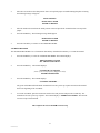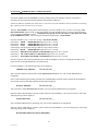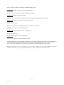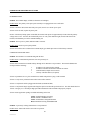
1
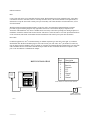
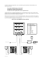
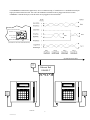
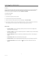
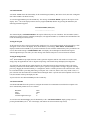
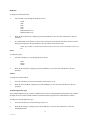
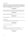
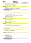
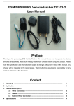
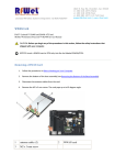
SERIES 2000 TIME AND DATA COLLECTION TERMINAL Accu-Time Systems, Inc. 420 Somers Road, Ellington, CT 06029 Tel: (860) 870-5000 Fax: (860) 872-1511 Web Site: www.accu-time.com Copyright 1992 Accu-Time Systems, Inc., Fourth Printing 2000. Accu-Time is a registered trademark of Accu-Time Systems, Inc. The material contained in this manual is subject to change. No part of this manual may be reproduced or distributed in any form or by any means, or stored in any database or retrieval system, without Accu-Time’s prior written permission. Accu-Time Systems, Inc. makes no warranty of any kind including, but not limited to, any implied warranties of merchantability, and fitness for a particular purpose in regard to this manual. All Rights Reserved. Printed in the USA. ACCU-TIME SERIES 2000 TABLE OF CONTENTS Introduction Features Specifications Installation 1 2 3 4 ACCU-RATE Diagnostics Ethernet Setup and Testing 9 14 Maintenance Troubleshooting Guide Ethernet Troubleshooting Guide 17 18 20 MANU2000-01(04) INTRODUCTION The Accu-Time Series 2000 is a true “C” programmable Time and Data Collection Terminal. Designed to be used in any time or data collection environment, the Series 2000 offers a large user memory base of up to 768K for file validation, local editing and scheduling functions. In addition to operating in standard EIA communication formats, the Series 2000 is also TCP/IP ETHERNET 10-base-T compatible. Among the many features of the Series 2000 are: Multi-Media: Can support most standard bar code formats including UPC, 128, 39, 2/5, I2/5 and more, as well as IATA Track I and ABA Track II magnetic stripe input. Flexibility: The Series 2000 can act as a stand alone time station or as part of a local or wide area network. The terminal can also interface with virtually any host hardware or software platform. Custom Applications: Custom programs and programmable function keys can provide users with the flexibility to create a variety of options. Reliability: A Real Time Clock (RTC) provides 12 or 24 hour time formats with quartz precision. An optional non-interruptible power supply (UPS) provides terminal operation for up to 4 hours during power outages. Data storage will be preserved for up to 4 days with the memory backup system. Durability: Environmental enclosure protects circuitry from environmental conditions such as extreme temperatures and airborne dust. Versatility, Reliability and Affordability in a state-of-the-art ergonomically designed terminal and backed by the ACCUTEAM. 1 MANU2000-01(04) FEATURES • Single or multi-clock environments on a variety of host platforms with application programs integrating the ATS DATA TRAKER family of modules. • 128K Byte capacitor backed memory base, expandable to 768K • TCP/IP ETHERNET 10-base-T compatible (802.3) • EIA Standard RS232 or RS485 compatible. 9600/19.2-Baud Modem operation • On-board ACCU-RATE terminal set-up and diagnostics package. • Dual tone audible annunciator • Custom keypad legends with software defined function keys • Large 20 key tactile 4x5 matrix keypad • 2 or 4 Line x 20 Character liquid crystal backlit display • Diagnostic LEDs for Ethernet—2 yellows, 1 green, and 1 red described in Troubleshooting Guide. • Integrated or External Bar Code or Magnetic slot readers • DI/DO port for access control • Optional Printer port • Digital Bar Code Wand port • Low voltage power source locally or remotely supplied • Non-interruptible power source with on-board charger • Die cast aluminum housing with steel key-lockable, tamper resistant base assembly • CE Mark and FCC part 15 Certified 2 MANU2000-01(04) SPECIFICATIONS Display: 4 Line x 20 Character backlit super-twist LCD 2 Line x 20 Character Vacuum Fluorescent Clock: 12 or 24 hour-format-USA or International (quartz precision) Time stamp of data transactions Indicators: Yellow LED Low Power indicator Two programmable LED indicators, RED and GREEN Diagnostic LEDs for Ethernet: Yellow = busy Green = linked Yellow = receive Red = Transmit Memory: 128K Byte of capacitor backed memory (I.e.; 600-employee base-program dependent) Expandable to 768K Byte (Over 2000-employee base—program dependent). Programming: ATS DATA TRAKER modules, “C” programming language or third party custom application packages. Interface: TCP/IP ETHERNET 10-base-T (802.3) EIA Standard RS232 or RS485 (2 or 4 wire) Standard AT Command set for internal 9600/19.2-Baud Modem operation. DI/DO or Serial Interface Printer port. Digital Bar Code Wand input port. Enclosure: Die cast aluminum housing with steel key-lockable base assembly Tamper switch (sends alarm message to host) Power: +10 to 17 VDC (+12 VDC @ 250 milliamps Nominal) Local, remote or centrally powered Non-interruptible power source with charger (optional) Environment: Operation: 32° to 110° F (0° to 43° C) Certification: CE Mark Certified (CE, RE, ESD, RS and CS), FCC part 15 Physical: 9.75” wide x 7.25” high x 3.8” deep. Weight: 6 LBS 24.77cm wide x 18.42cm high x 9.65cm deep. Weight: 2.72kg Accessories: Integrated or External Optical Bar Code slot readers Integrated Magnetic slot readers Wiegand and RF ID readers Digital Bar Code Wands Solid State or Dry Contact relay modules Serial Interface Printer Port 3 MANU2000-01(04) INSTALLATION GENERAL INSTALLATION GUIDELINES Environment Although the Series 2000 Time and Data Collection Terminal is a durable industrial-grade device, which will endure harsh environments, it never the less is an electronic device. Environmental constraints exist and care should be given when selecting a location for installing and operating the Series 2000. The ATS terminal is designed to operate indoors. Exposure to outdoor elements such as rain or snow will not only void the manufacturer warranty, but may cause damage to the device. Select a location, which has adequate lighting and accessibility to operate the terminal safely. Operating parameters Accu-Time recommends the Series 2000 operate in an ambient temperature range of between 32° and 110° Fahrenheit. Non-condensing humidity should be less than 95%. The terminal should be mounted on a vibration free area. The RS232 Series 2000 must be located no greater than fifty (50) wire-feet from the host computer. EIA standards for RS232 protocol data transmission dictate this cable distance. Exceeding this requirement greatly increases the chances for continual data re-transmission, which may never be acknowledged. The RS485 Series 2000 locally powered must be located no greater than five thousand (5000) wire-feet from the host computer. EIA standards for RS485 protocol data transmission dictate this cable distance. Exceeding this requirement greatly increases the chances for continual data re-transmission, which may never be acknowledged. The ETHERNET Series 2000 may be located at any point within a TCP/IP ETHERNET 10-BASE-T Network, providing the single segment length from the network hub does not exceed three hundred and twenty-eight (328) wirefeet. A typical topography for the Series 2000 in an ETHERNET 10-BASE-T network is a star configuration. 4 MANU2000-01(04) INSTALLATION Base Locate a flat wall surface to accommodate the Series 2000. With terminal power being supplied locally, insure that a conventional 110VAC wall outlet, 220VAC in Europe and other areas, (check local electrical code requirements) is dedicated to accept the Series 2000 12VDC power pack assembly. The outlet should be no further than four (4) feet from the terminal. With the supplied terminal mounting template, prepare the wall to accommodate mounting hardware (customer provided). Typical mounting height is forty-eight inches from floor to the terminal display (Compliant to the Americans with Disabilities Act). Observe OSHA and/or local safety codes when operating tools during all phases of installation. Attach the terminal wall mount to the flat wall surface. Select and remove one of the perforated knockouts on the wall mount, which will accommodate the data transmission and 12VDC power pack cable assemblies. Data Cable For RS232 applications, ATS recommends using its modular telephone type data cable. This eight- (8) conductor shielded flat cable has RJ-45 modular plugs on each end. The fifty (50) foot cable, ATS part number (63-2003-02), may run along side base-moldings, walls, overheads, or in hostile environments through conduit tubing. One end of the cable terminates into the Series 2000 communication port while the other terminates into the host computer’s serial port via an ATS RS232 Communication Adapter. RS232 INSTALLATION 12 VDC POWER SUPPLY ACCU-TIME SYSTEMS ELLINGTON, CT LOW INVALID VALID POWER 1 2 3 F1 F5 4 5 6 F2 F6 7 8 9 F3 F7 ENTER F4 F8 CLEAR 0 Pin # 1 2 3 4 5 6 7 8 Description Earth Ground Receive Transmit N/C N/C Ground +VDC Ground NOTE: Pinouts are referenced to the terminal TO HOST COMM ADAPTER DB25-RJ45 W/PWR 2kPO.DRW 5 MANU2000-01(04) For RS485 communication applications, ATS recommends using a data transmission cable that adheres to the following specifications: Five conductor shielded 24-gage wire with a drain. The impedance of the cable should be 100 Ohms. The capacitance should be 12 pico-farads per foot. The jacket of the cable is typically either a PVC or Plenum material. (*NOTE* If the host is not equipped with an RS485 port, an ATS RS232/485 Converter with 12 volt power pack assembly will convert the terminal communication lines to RS232 levels. The host output of the RS232/485 Converter plugs directly into the ATS RS232 Communication Adapter.) RS485 allows for the Series 2000 to be used in multi-dropped networks. Thirty-two (32) terminals can be supported on a single host communication port. The use of ATS Series 1000 Network Controllers allow up to five hundred and twelve (512) terminals on a single host communication port. MULTI-CLOCK RS485 INSTALLATION 1 2 3 5 4 1 2 3 4 5 7 8 P.GND E.GND CO M M 6 +VDC 5 4 P.GND 3 +VDC 2 8 P.GND 1 7 P.GND E.GND CO M M 6 6 7 8 P.GND +VDC P.GND E.GND COMM Pin # 1 2 3 4 5 6 7 8 D C PO W ER JP2 JP1 NC JP3 D RO P 1 JP4 NC NO D RO P 2 DR OP 3 NO Description Earth Ground DI DO + DO DI + Ground +VDC Ground E. GN D D RO P 4 NOTE: Pinouts are referenced to the terminal 12 VDC POWER SUPPLY RS-232 TO RS-485 CONVERTER NETWORK CONTINUED TO HOST COMM ADAPTER DB25-RJ45 W/PWR 12 VDC POWER SUPPLY ACCU-TIME SYSTEMS ACCU-TIME SYSTEMS ELLINGTON, CT LOW INVALID ELLINGTON, CT VALID LOW POWER VALID F1 F5 1 2 3 F1 F5 4 5 6 F2 F6 4 5 6 F2 F6 7 8 9 F3 F7 7 8 9 F3 F7 CLEAR 0 ENTER F4 F8 CLEAR 0 ENTER F4 F8 6 MANU2000-01(04) INVALID POWER 1 2 3 12 VDC POWER SUPPLY For ETHERNET communication applications, ATS recommends using a CATEGORY 4 or 5 unshielded twisted pair high-speed data transmission cable. One end of the 568B RJ45 terminated cable is plugged into the Series 2000 ETHERNET communication port, while the other end is plugged into the network hub. Ethernet Communication Port Wand Port T U Test/Use Switch Power Port Optional UPS Battery DI/DO Port (Sectional Cut-out of the Terminal Chassis) System Network Cable Hub POWER SUPPLY Ethernet Hub 10BASE-T ACCU-TIME SYSTEMS ACCU-TIME SYSTEMS ELLINGTON, CT ELLINGTON, CT INVALID LOW LOW VALID ATS 12VDC POWER SUPPLY 1 2 3 F1 F5 4 5 6 F2 F6 7 8 9 F3 F7 ENTER F4 F8 CLEAR VALID 0 1 2 3 F1 F5 4 5 6 F2 F6 7 8 9 F3 F7 0 F4 F8 CLEAR 2KFPENET.DRW MANU2000-01(04) INVALID POWER POWER 7 ENTER ATS 12VDC POWER SUPPLY Terminal Face Align the faceplate of the Series 2000 over the base assembly. Plug the 26-conductor ribbon cable into the communication interface board housed in the base of the terminal. Plug the data cable through one of the perforated knockouts of the base assembly and into the communication port of the Series 2000. Attach the output of the 12VDC power pack assembly into the power jack of the Series 2000. Plug the primary of the power pack assembly to the conventional wall outlet. With the terminal’s USE/TEST switch in the USE mode, attach the face to the base assembly. Secure the assemblies with the key or screw lock. The Series 2000 will power-up and display the on-line default message. (Refer to the ATS SETUP MODE section of this manual for terminal communication setup parameters) Attach the remaining end of the data cable into the host computer port. The Series 2000 is now ready for operation. Tamper Switch ATS R ACCU-TIME SYSTEMS ELLINGTON, CT INVALID LOW DI/DO Port TEST SWITCH TEST USE Host Communication POWER VALID ON OFF Power LED POWER 1 2 3 F5 4 5 6 F6 9 F7 7 8 CLEAR 0 ENTER F4 Power Jack Battery Port Wand Port F8 I/O to Terminal Interface Battery (Base Assembly) (Terminal Face) 8 MANU2000-01(04) ACCU-RATE SET-UP AND DIAGNOSTICS POWER UP To power up the Series 2000 a 12VDC source must be applied to the terminal power jack. The Series 2000, with the POWER ON/OFF switch placed in the ON position and the TEST/USE switch placed in the USE mode, beeps, executes a power up sequence and displays the message “TERMINAL LOCKED”. ACCESSING TEST MODE To access the test mode: 1) Unlock the base assembly on the Series 2000. 2) Locate the Test/Use switch on the I/O board assembly. 3) Slide the switch into the TEST position. The Series 2000 displays “ATS TEST MODE”. 4) By pressing the CLEAR key, the user can step through the selections. (*NOTE* Test mode may be exited at any time by placing the Test/Use switch back to the USE position and pressing the CLEAR key). SELECTIONS: • ATS TEST MODE: Tests the Keypad, Display, Memory, Real Time Clock, Bar Code or Magnetic Slot reader and Bar Code Wand circuitry. • ATS SET-UP MODE: Configures the communication parameters—Baud Rate, Parity Bit, Terminal Address, and Terminal Application Type. • ATS NETWORK TEST: Performs a terminal to host communication loop-back test. Verifies integrity of cabling. • ATS BATTERY TEST: Checks the terminal battery backup option. • ATS DI-DO TEST: Checks the Digital Input/Digital Output auxiliary port by performing a loop-back test. • ATS RESTART MODE: Resets the terminal, clears all data from memory and performs a power-up sequence. 9 MANU2000-01(04) ATS TEST MODE: ATS TEST MODE checks the functionality of the terminal Keypad, Memory, Real Time Clock, Bar Code or Magnetic Slot reader and Bar Code Wand circuitry. To enter the TEST MODE, press the ENTER key. The message “ATS TEST MODE” appears on the top line of the nd display. The 2 line of the display indicates the two program (EPROM) numbers. By pressing the ENTER key the following information appears: ATS TEST MODE (XXX) (YY) ---------------------The terminal displays ATS TEST MODE on the top line followed by two sets of numbers. The first number (XXX) indicates the amount of memory installed (in Kilobytes). The right most number (YY) indicates the terminal Real Time Clock incrementing in seconds (00-59). Testing the Keypad At this time the user may test the keypad assembly. Each time a key is pressed the terminal will beep and the key value nd will appear on the 2 line of the display. Press the ENTER key. The message “KEY INPUT ACCEPTED” is displayed. Each time the ENTER key is pressed an internal test of the terminal communication port is performed. If an error is detected the message “COMM PORT FAIL” will display, the invalid light will flash and the negative acknowledgement beeper tone will cycle. This message will continue until power is removed from the terminal. Testing the Badge Reader ATS TEST MODE accepts inputs from slot readers (optical or magnetic) and bar code wands. To test the reader, simply swipe the applicable bar code or magnetic stripe badge. The terminal beeps and displays the badge data. To test the bar code wand, the user lightly drags the tip of the wand across the bar code badge or label. The wand should be positioned in the hand (similar to that of a pen or pencil) at an approximate 30ο angle. Begin the scanning process by dragging the wand horizontally, in a straight line, and at a constant speed across the entire label area. Each bar code label includes a preceding and trailing ¼ inch quiet zone. This area, which is free of any marks or bars, is a part of the bar code label and must be included when scanning the label. Upon the successful completion of a bar code read, the terminal will beep and display the data. To proceed to the ATS SETUP MODE press the CLEAR key. ATS SETUP MODE ATS SETUP MODE allows the operator to configure the terminal for communications with the host computer. The Series 2000 default parameters are set as follows: Baud Rate Parity Address Terminal Application Type 9600 ODD 01 A To enter the ATS SETUP MODE, press the ENTER key at the “ATS SETUP MODE” display prompt. (Prior to nd pressing the ENTER key the 2 line of the display will indicate the current terminal setup values) 10 MANU2000-01(04) Baud Rate To change the terminal baud rate: 1. Press CLEAR to step through the baud rate choices: 19200 9600 4800 2400 1200 M1200 modem (N/A) M2400 modem (N/A) 2. When the desired baud rate is displayed, press the ENTER key to store the value and advance to the next parameter. 3. If a modem baud rate is selected, a self-test will be performed on the modem. The results of this test will be displayed. The operator will be prompted to enter the number of auto answer rings. NOTE: If no modem is installed and a modem baud rate has been selected, the modem self test will fail. Parity To change the parity: 1. Press the CLEAR key to step through the parity choices: ODD EVEN NONE 2. When the desired parity is displayed, press the ENTER key to store the value and advance to the next parameter. Address To change the terminal address: 1. Press the CLEAR key to increment the address values from 01 to 32. 2. When the desired address is displayed, press the ENTER key to store the value and advance to the next parameter. Terminal Application Type The Terminal Application Type is used as a delimiter by the host for routing application information to the terminal. (Example-an access control terminal could have a different terminal type than a time and attendance terminal) To change the terminal application type: 1. Press the CLEAR key to increment the type from A to J. 2. When the desired type is displayed, press the ENTER key to store the value and advance to the ATS NETWORK TEST. 11 MANU2000-01(04) ATS NETWORK TEST ATS NETWORK TEST is a two-part test. The first allows the network wiring between the terminal and the host to be checked for open connections or wiring errors. This test requires that the ATS RS232 Communication Adapter which is plugged into the host, be unplugged and pins 2 & 3 of the adapter jumped together (a paper clip should do the trick). Secondly, a local test can be performed on the terminal communication circuitry. This test will work for both RS232 and RS485 installations (RS485 installations require an ATS 232/485 Converter). To enter NETWORK TEST, press the ENTER key at the “ATS NETWORK TEST” prompt. The following message appears: SWITCH TEST SWITCH TO USE POSITON Place the switch on the back of the terminal into the USE position. The Series 2000 performs a network test in which the terminal sends data up to the host, via the network cabling. Since a temporary jumper was installed in the ATS RS232 Communication Adapter, the data will be looped back to the terminal. The following message should appear: NETWORK TEST PASS ENTER TO RETEST To perform the local communication loop back, place the USE/TEST switch back to the TEST position and press the ENTER key. The following message should appear: NETWORK TEST PASS ENTER TO RETEST Remove the jumper from the RS232 Communication Adapter and secure it back into the host port. Press the CLEAR key to advance to the next test. ATS BATTERY TEST The ATS BATTERY TEST checks the terminal battery backup option if installed. To enter this test, press the ENTER key at the “ATS BATTERY TEST” prompt. The following message should appear: BATTERY TEST PASS ENTER TO RETEST Note: If the battery backup option is not installed, the battery test will fail. Press CLEAR to advance to the ATS DI-DO Test. ATS DI-DO TEST The ATS DI-DO Test is a two-part test that checks the terminal auxiliary DATA IN/DATA OUT port connection by performing a loop back communication test on the port circuitry. To enter the ATS DI-DO Test: 1. Press the ENTER key at the “ATS DI-DO TEST” prompt. The following message should appear: SWITCH TEST SWITCH TO USE POSITION 12 MANU2000-01(04) 2. Place the test switch into the USE position. Since no loop back jumper is installed during this phase of testing the following message will appear: DI-DO TESTING DI-DO TEST FAILED ENTER TO RETEST 3. Place the TEST/USE switch into the TEST position. This will provide the terminal with its own loop back jumper. 4. Press the ENTER key. The following message should appear: DI-DO TEST PASSED ENTER TO RETEST 5. Press the CLEAR key to advance to ATS RESTART MODE. ATS RESTART MODE The ATS RESTART MODE clears all transaction data and any download from memory. To restart the terminal: 1. Press the ENTER key to select the ATS RESTART MODE. The terminal displays: PRESS ENTER TO CLEAR ALL TRANSACTION DATA 2. Press the ENTER key. The terminal displays: CLEAR FOR CYCLE TEST (Note: Cycle test is for factory diagnostics only) ENTER FOR RESTART 3. Press the ENTER key. The terminal displays: CLEARING MEMORY. . . The green Valid LED will blink and the terminal will execute a power up sequence and return the terminal back to the beginning of the Test Mode. 4. To exit the Test Mode, place the TEST/USE switch to the USE position and press the CLEAR key. The terminal will execute a power up sequence. The terminal displays: “TERMINAL LOCKED” The terminal can now accept a host download. This completes the ACCU-RATE test and set-up 13 MANU2000-01(04) ACCU-RATE ETHERNET SET-UP AND DIAGNOSTICS ATS TEST MODE checks the ETHERNET circuitry installed in the Time and Data Collection Terminals. To accurately test this circuit the following sequential steps should be adhered to. NOTE: The Ethernet communication cable must be connected to the Time and Data Collection Terminal with running Host software for this operation to be successful. With the “TEST MODE” message in the terminal display, press the CLEAR key five (5) times. The message “ATS RESTART MODE” appears on the top line of the display. Press the ENTER key three (3) times to clear all memory prior to testing the ETHERNET circuit. (Omitting this step greatly increases the chances of unreliable test results in the ETHERNET circuit). After resetting the terminal will again display “TEST MODE”. Press the CLEAR key one (1) time. The message “ATS SETUP MODE” 000.000.000.000 displayed for one (1) second Followed by: TERM 000.000.000.000 displayed for one (1) second Followed by: HOST 000.000.000.000 displayed for one (1) second Followed by: GATE (This message will only appear if the gate address was previously loaded.) 000.000.000.000 displayed for one (1) second Followed by: MASK Followed by: BROADCAST ENABLED or DISABLED displayed for one (1) second Followed by: APP ACK ENABLED or DISABLED displayed for one (1) second Followed by: WATCHDOG ENABLED or DISABLED displayed for one (1) second The above sequence will repeat itself until either the CLEAR or ENTER key is pressed. Pressing the CLEAR key will bypass the test. Pressing the ENTER key will enable the test. Press the ENTER key. The following message will be displayed: TERMINAL IP ADDRESS ###. ###. ###. ###. _ _ _ This is the Time and Data Collection unit’s unique Internet Protocol address. (See your network administrator for assignment.) Enter, via the terminal keypad assembly, the numeric IP Terminal address in blocks of three followed by the ENTER key. Once all four octets are entered the following message will be displayed: HOST IP ADDRESS ###. ###. ###. ###. _ _ _ This is the Host’s unique Internet Protocol address. (See your network administrator for assignment.) Enter the numeric IP Host address in blocks of three followed by the ENTER key. Once all four blocks are entered the following message will be displayed: NETWORK MASK ###. ###. ###. ###. _ _ _ This is the Subnet Mask used for channeling. (See your network administrator for assignment). Enter the numeric Mask address in blocks of three followed by the ENTER key. Once all four blocks are entered the following message will be displayed: HIT ENTER IF DEFAULT ROUTE REQUIRED 14 MANU2000-01(04) If a Router or Gateway is required press the ENTER key. The following message will be displayed: ROUTER IP ADDRESS ###. ###. ###. ###. _ _ _ This is the system Router used for directing internet traffic among a variety of Hosts. (See your network administrator for assignment.) Enter the numeric Router or Gateway address in blocks of three followed by the ENTER key. The next message allows an enablement of the Broadcast Receive command. If this function is disabled, all broadcast packets will be ignored by the terminal. HIT ENTER TO ENABLE BROADCAST RECEIVE Disabling Broadcast Receive may be accomplished by pressing the CLEAR key (recommended for networks with heavy traffic). Upon disablement, only devices connected to the same IP address will be able to “Ping” terminals. The Application Acknowledgement message assures that the Host has received the last transaction, which enhances data integrity by affirming that the transaction has not been held up in a router/gateway or lost. The terminal will display the following: HIT ENTER TO ENABLE APPLICATION ACK Application Acknowledgement may be disabled by pressing the CLEAR key. The next message, TCP/IP Watchdog, provides a “soft restart” if the connected terminal has not communicated with the Host for approximately ten- (10) minutes. The terminal will display the following message: HIT ENTER TO ENABLE TCP/IP WATCHDOG Pressing the CLEAR key will disable TCP/IP Watchdog. The following message allows the Ethernet communication connection. ENETADD=XXXXXXXXXXXXHIT ENTER TO CONNECT The XXXXXXXXXXXX represents the unique Ethernet address programmed into the EPROM by the factory. If a Router is not required, press the CLEAR key. The following message will be displayed: ENETADD=XXXXXXXXXXXXHIT ENTER TO CONNECT The XXXXXXXXXXXX represents the unique Ethernet address programmed into the EPROM by the factory. Press the ENTER key or the CLEAR key if connection is not required. The terminal will briefly display an initializing message followed by: CONNECTING TO SERVER If the connection to the server was successful the following message is displayed: CONNECTION COMPLETE If the connection to the server was not successful the following message is displayed: CONNECTION FAILED!! HIT ENTER TO CONNECT 15 MANU2000-01(04) Press the ENTER key. The terminal will display the following: CLOSING CONNECTION BEFORE RECONNECTION Followed by the brief initializing message and connecting message: CONNECTING TO SERVER At this time the terminal will either complete the connection or fail. If a connection failure occurs after numerous attempts, see the troubleshooting section of this manual for further assistance. This completes the ACCU-RATE ETHERNET test Downloading the Series 2000 The Series 2000 terminal, when used with the standard Time and Attendance "C" application, can be downloaded with employee names, badge numbers, schedules, etc. These download commands and others are explained in the ATS DATA TRAKER command set manual. For further information refer to this manual. 16 MANU2000-01(04) MAINTENANCE The Series 2000 is a maintenance-free data collection device. The only required procedure is periodic cleaning of the badge reader. To clean the badge reader, swipe a pre-moistened (isopropyl alcohol) cleaning card through the reader several times. Low usage readers should be cleaned monthly. High usage readers should be cleaned weekly. 17 MANU2000-01(04) TROUBLESHOOTING GUIDE Problem: Terminal does not power up and none of the status LEDs are lit. Possible cause: No DC power applied Solution: Ensure primary side of DC power pack assembly is plugged into a live AC outlet. Ensure secondary side of DC power pack assembly is plugged into the Time and Data Collection Terminal (DCT). Solution: Check the fuse on the I/O board. Problem: Terminal display is blank (no character or backlight). Possible cause: The primary of the power pack assembly is not plugged into an AC-wall outlet. Solution: Test the outlet by plugging in another appliance or check that the secondary supply is plugged into the terminal. Solution: If all else fails, replace the power pack assembly. NOTE: If the battery backup option is installed, the terminal will operate for approximately 4-hours when the primary voltage source is lost. After this, the terminal will power off. The yellow indicator light, located on the front of the terminal, will illuminate prior to the terminal blanking out. Problem: Yellow Low Power indicator is lit. Possible cause: Low DC power is attached. Solution: Replace 12-volt DC power pack. Possible cause: Terminal does not go blank after unplugging the battery connector. Solution: Unplug and replace the power pack assembly. Problem: Terminal is not communicating with Host. Possible cause: The terminal TEST/USE switch is in the TEST position Solution: Place the TEST/USE switch is in the USE position. Possible cause: DCT to Host communication cable is defective or unplugged on either end. Solution: Verify cable is tested and plugged into both ends. (Ensure cable termination guidelines and lengths are observed.) Solution: Ensure the application package is loaded and running on the host. Possible cause: Communication parameters for the DCT do not match those of the Host. Solution: Refer to the ACCU-RATE test and diagnostics section for set-up directions. Problem: DCT does not accept badge data. Possible cause: Bar code badge is not manufactured to proper specification. 18 MANU2000-01(04) Solution: Refer to vendor’s specifications for manufacturing criteria. Possible cause: Badge is being swiped in the wrong direction. Solution: Ensure media faces to the right (away from the keypad). Possible cause: Badge reader needs cleaning. Solution: Swipe a pre-moistened (isopropyl alcohol) cleaning card through the reader several times. Possible cause: Badge number does not exist in validation file. Solution: See Supervisor Note: If all solutions fail try reading badge in the ACCU-RATE test mode. Problem: Terminal does not accept keypad input. Possible cause: Keyed data does not exist in validation file Solution: See Supervisor Possible cause: Keypad connector is unplugged. Solution: Test keypad in the ACCU-RATE test mode. If all solutions have been explored and the problem still exists, contact the Accu-Time Product Service Department at (860) 870-5000 during normal working hours 9 AM to 5 PM- Monday through Friday. Prior to contacting AccuTime, please have available the serial number and if possible the configuration number of the product. NOTE: The DCT has no user serviceable parts. The Accu-Time terminal must be operated within the parameters included in this manual. Any operation performed contrary to these parameters will void the warranty 19 MANU2000-01(04) ETHERNET TROUBLESHOOTING GUIDE POWER RELATED Problem: The terminal display is blank (no characters or backlight). Possible cause: The primary of the power pack assembly is not plugged into an AC-wall outlet. Solution: Check the outlet, both ends of the power pack, and if it is a 12VDC power pack. Solution: If all else fails, replace the power pack. NOTE: If the battery backup option is installed, the terminal will operate for approximately 4-hours when the primary voltage source is lost. After this, the terminal will power off. The yellow indicator light, located on the front of the terminal, will illuminate prior to the terminal blanking out. Problem: The low power (yellow) indicator LED is activated. Possible cause: Outlet or power pack problem. Solution: Perform the above solution if the terminal display goes blank upon removal of the battery connector. COMMUNICATION RELATED Problem: The terminal is not communicating with the host. Possible cause: Communication parameters were not previously set. Solution: Place terminal in Test Mode and step through ACCU-RATE Test procedures. The network administrator would provide the following: IP address to be assigned to the terminal • IP address of the host to which the terminal can connect • Network Mask (example 255.255.255.0) • Gateway or Router address (if required) • Solution: If parameters are set, place terminal in Use Mode and perform a "ping" on the terminal. Solution: Verify activity of LEDs located on the bottom of the terminal. Solution: Verify that the cable is plugged into both ends (terminal and hub). Solution: Verify that the single segment cable length is equal or less than the specified 328 feet. The cable should also be a 10-base-T category 4 or 5 twisted pair high-speed data transmission cable with both ends properly crimped. Solution: Insure application package is loaded and running on the host. Yellow: terminal is BUSY processing Green: terminal is LINKED to host Yellow: terminal data is being RECEIVED Red: terminal data is being TRANSMITTED Problem: A previously working terminal now is not operational. Possible cause: TEST/USE switch is not in the Use position. 20 MANU2000-01(04) Solution: Place TEST/USE switch in Use position. Possible cause: Cables not plugged in or host application software not operational. Solution: Insure that all connections are made and that the host software application is functional. If possible, take a known working terminal, re-address it for this particular node and determine if the problem is related to the terminal, installation or host. PERIPHERAL FAILURE Problem: Bar code reader does not work. Possible cause: The employee badge has not been added to the application database. Solution: Place the TEST/USE switch into the Test position and swipe test badges to verify reader functionality. Solution: If the reader works in the Test Mode and not in the Use Mode, verify that the employee badge has been added to the application database. Problem: Keypad does not work. Possible cause: Keypad function has been disabled in the application. Solution: Place the TEST/USE switch to the Test Mode and press random keys to verify keypad functionality. Solution: Insure that the keypad function within the application is activated. If neither the standard nor Ethernet troubleshooting guide is of any help, please contact the Accu-Time Product Service Center, (860) 870-5000, for further assistance. 21 MANU2000-01(04) FCC Statement This equipment has been tested and found to comply with the limits for a Class A digital device pursuant to Part 15 of the FCC rules. These limits are designed to provide reasonable protection against harmful interference in a residential installation. This equipment generates, uses, and can radiate radio frequency energy and, if not installed and used in accordance with the instructions, may cause harmful interference to radio communications. However, there is no guarantee that interference will not occur in a particular installation. If this equipment does cause harmful interference to radio or television reception, which can be determined by turning the equipment off and on, the user is encouraged to try to correct the interference by one or more of the following measures: * * * Reorient or relocate the receiving antenna. Increase the distance between the time clock and the receiver. Connect the equipment into an outlet on a circuit different from that which the receiver is connected. FCC Warning: To assure continued FCC emission limit compliance, the user must use only the recommended shielded interfacing cable when connecting to a host computer. Also, any unauthorized changes or modifications to this equipment would void the user authority to operate this device. 22 MANU2000-01(04) 23 MANU2000-01(04) "B" "A" "A" When securing to a flat wall, use the mounting-hole pattern, labeled "A". The hole pattern labeled "B" may accomodate power and communication wiring. "A" SERIES 2000 MOUNTING TEMPLATE