1
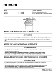
PC3500TX Terminal
Installation &
User’s Guide
Limited One-Year Limited Warranty
Lathem warrants the hardware products described in this guide against defects in material and workmanship for a
period of one year from date of original purchase from Lathem or from an authorized Lathem reseller. The
conditions of this warranty and the extent of the responsibility of Lathem Time Corporation (“Lathem”) under this
warranty are listed below.
1.
2.
3.
4.
5.
6.
7.
8.
9.
This warranty will become void when service performed by anyone other than an approved Lathem
warranty service dealer results in damage to the product.
This warranty does not apply to any product which has been subject to abuse, neglect, or accident, or
which has had the serial number altered or removed, or which has been connected, installed, adjusted,
or repaired other than in accordance with instructions furnished by Lathem.
This warranty does not cover dealer labor cost for removing and reinstalling the machine for repair,
or any expendable parts that are readily replaced due to normal use.
The sole responsibility of Lathem under this warranty shall be limited to repair of this product, or
replacement thereof, at the sole discretion of Lathem.
If it becomes necessary to send the product or any defective part to Lathem or any authorized service
dealer, the product must be shipped in its original carton or equivalent, fully insured with shipping
charges prepaid. Lathem will not assume any responsibility for any loss or damage incurred in
shipping.
WARRANTY DISCLAIMER AND LIMITATION OF LIABILITY: Except only the limited express
warranty set forth above, the products are sold with no expressed or implied warranties of any kind,
and the implied warranties of merchantability and fitness for a particular purpose are hereby
expressly disclaimed. No warranties are given with respect to products purchased other than from
Lathem or an authorized Lathem reseller and any such products are purchased "as is, with all faults."
In no event will Lathem be liable for any direct, indirect, special, incidental or consequential damages
arising out of or in connection with the delivery, use or inability to use, or performance of this
product. In the event any limited remedy given herein shall be deemed to have failed of its essential
purpose, Lathem's maximum liability shall be to refund the purchase price upon return of the product.
Proof of date of purchase from Lathem or an authorized Lathem reseller is required for warranty
service on this product.
This Warranty grants specific legal rights. Additional legal rights, which may vary by locale, may
also apply.
Should any difficulties arise with the performance of this product during warranty, or with any
Lathem authorized service centers, contact Lathem Time at the address below.
Lathem Time
200 Selig Drive, SW, Atlanta, GA 30336
404-691-0405
www.lathem.com
Copyright © 2003 Lathem Time Corporation. All rights reserved.
Document number: USG0031I
Revised 8-04-2006
PayClock, Lathem and the Lathem logo are registered trademarks of Lathem Time Corporation. Other product names
mentioned in this manual may be trademarks of their respective companies and are hereby acknowledged.
Warning: Changes or modifications to this unit not expressly approved by the party responsible for compliance could void
the user’s authority to operate the equipment.
NOTICE: This equipment has been tested and found to comply with the limits for a Class A digital device, pursuant
to Part 15 of the FCC Rules. These limits are designed to provide reasonable protection against harmful interference
when the equipment is operated in a commercial environment. This equipment generates, uses, and can radiate radio
frequency energy and, if not installed and used in accordance with the instructional manual, may cause harmful interference
to radio communications. Operation of this equipment in a residential area is likely to cause harmful interference in which
case the user will be required to correct the interference at his or her own expense.
CONTENTS
WELCOME.....................................................................................................................................1
FEATURES AND SPECIFICATIONS ....................................................................................................1
MOUNTING THE TERMINAL ...................................................................................................3
PRE-TERMINAL INSTALLATION ......................................................................................................3
MOUNT THE TERMINAL .................................................................................................................3
CONNECT THE COMMUNICATION CABLE.........................................................................6
SETUP THE TERMINAL .............................................................................................................7
SETUP MODE .................................................................................................................................9
To Setup the PC3500TX’s Ethernet Communications....................................................................9
TEST MODE .................................................................................................................................15
To Test the Keypad ..........................................................................................................................15
To Test the Badge Reader................................................................................................................15
Battery Test.......................................................................................................................................16
DI-DO Test........................................................................................................................................16
Restart Mode ....................................................................................................................................17
UNLOCKING YOUR TERMINAL THROUGH TERMINAL MANAGER .................................................17
USE THE TERMINAL ................................................................................................................18
To punch .................................................................................................................................18
To transfer ..............................................................................................................................19
To start a New Day .................................................................................................................19
To enter amounts ....................................................................................................................19
To reveiw your last punch.......................................................................................................19
To see employee Info...............................................................................................................20
SUPERVISOR FUNCTIONS .............................................................................................................20
To Add an Employee Punch....................................................................................................20
INSTALL/REPLACE THE OPTIONAL BACKUP BATTERY .............................................21
OPTIONAL SIGNAL DEVICE ..................................................................................................22
NETWORK WIRING TOPOLOGIES.......................................................................................23
TROUBLESHOOTING THE TERMINAL...............................................................................25
TERMINAL DATA SHEET........................................................................................................29
PC3500TX Terminal Installation & User’s Guide - 1
CHAPTER 1
Welcome
Reliability, functionality and ease of use are trademarks of the PayClock terminals. Using
Lathem time and attendance software and your computer, PayClock terminals are the
perfect solution for businesses that want to track employee time and automate payroll.
PC3500TX NOTICE – For Firmware 177B and Earlier
¾Windows 98 2nd edition or later is required
¾PayClock Pro version 3.353 to 3.355G is required
PC3500TX NOTICE – For Firmware 177G and Later
¾Windows 2000 or Windows XP is required
¾PayClock Pro version 4.1 or later is required
Features and Specifications
Display:
Terminal:
4 Line x 20 Character back-lit super-twist LCD
12 or 24 hour-format, USA or International, quartz-precision TimeStamp on data transactions
Indicators:
LED’s indicate low Power (yellow), Invalid registration (red) and
Valid registration (green).
Diagnostic LEDs for Ethernet, Busy (yellow), Linked (green),
Receive (yellow), Transmit (red)
Communications: TCP/IP ETHERNET 10-base-T compatible
Input:
Keypad and bar code slot reader. Badges are bar code format 3 of 9
or Interleave 2 of 5
Casing:
Die cast aluminum housing with steel key-lockable mounting plate.
Large 20 key tactile 4x5 matrix keypad. 9.75" wide X 7.25" high X
3.8" deep, 6 LBS
Power:
+10 to +17VDC (+12VDC @ 250 milliamps Nominal). An optional
non-interruptible power supply (UPS) provides operation for up to 4
hours during power outages
Environment:
Certification:
Operation: 32° to 110° F (0° to 43° C)
CE Mark Certified (CE, RE, ESD, RS and CS), FCC part 15
2 - PC3500TX Terminal Installation & User’s Guide
Cable Specs:
Capacities:
Category 4 or Category 5 unshielded twisted pair high-speed data
transmission cable. Note: All cables must conform to local
building/electrical codes. Consult a qualified installer
Employee
600
Departments 290
Transactions 900 (approximate)
Power Surges and Spikes
Any time your terminal is connected to AC current, a power surge or spike can occur.
You should use high quality surge suppressers to protect your PC3500TX. The warranty
does not cover damage caused by power surges or spikes.
Note about Lithium Battery
This product’s lithium battery contains Perchlorate Material – special handling may
apply. Please go to web site www.dtsc.ca.gov/hazardouswaste/perchlorate for
information about proper methods of disposal in California.
PC3500TX Terminal Installation & User’s Guide - 3
CHAPTER 2
Mounting the Terminal
Pre-Terminal Installation
Before deciding where to mount the terminal, you will need to verify that it will be
within 4 feet of an 115VAC power outlet. The outlet should not be located near devices
that may cause interference on the line such as refrigerators, microwave ovens, welders,
etc.
The PC3500TX may be located at any point within a TCP/IP Ethernet 10-Base-T
network, as long as the section of cable between the network switch and PC3500TX does
not go beyond three hundred and twenty eight (328) wire-feet. A typical topography for
the PC3500TX in an Ethernet 10-Base-T network is a star configuration.
NOTE: It is recommended that the PC3500TX be plugged into a switch.
Included with the terminal is a label that is used to note specific information about the
terminal. This information should be written on the sticker and placed on either side or
the bottom of the terminal. This will be used when the terminal is setup or in
troubleshooting. The information will come from your Network Administrator.
This information includes the terminals: IP Address (this must be a static IP address),
Subnet Mask and Gateway. This information should also be written on the Terminal Data
Sheet found near the end of this document.
NOTE: Lathem representatives cannot issue or obtain this information. You must see
your network administrator prior to beginning the installation for this information.
Mount the Terminal
The PC3500TX is designed to operate indoors. You should use the terminal where the
temperature is between 32°-110° F and humidity is less than 95%. You should choose a
place where the terminal cannot vibrate. Exposure to outdoor conditions such as rain or
snow voids the warranty and can damage the terminal.
4 - PC3500TX Terminal Installation & User’s Guide
To install the mounting bracket
♦
Locate a flat wall surface. Make sure you can plug the terminal into a 110VAC wall
outlet (220VAC in Europe and other areas), which should be no farther than 4 feet
from the terminal.
♦
Place the bottom of the mounting template on the wall 48 inches from the floor and
tape the template into place.
♦
Drill the 3 holes noted on the template using a 5/16” drill bit. If wires will be routed
through the wall, drill up to a 3/4" hole as indicated on the template. Remove the
template.
♦
Insert a wall anchor in each of the 5/16" holes and tap with a hammer until flush
with the wall.
♦
Align the mounting bracket with the anchors, (pull wiring through the hole in the
middle of the case if wires are being routed from the wall), insert the 3 screws and
tighten with a phillips head screwdriver.
PC3500TX Terminal Installation & User’s Guide - 5
♦
If all wiring is not routed from the wall, remove one of the mounting bracket
knockouts, so you can run the communication cable and 12VDC power pack cable
to the terminal.
♦
Insert the key into the mounting bracket lock and turn the key counter clockwise.
♦
Align the slots on the back of the terminal with the tabs on the top of the mounting
bracket. Plug in the power pack and communications cable, then lower the terminal
into place.
♦
Turn the key clockwise to lock the terminal in place.
6 - PC3500TX Terminal Installation & User’s Guide
CHAPTER 3
Connect the Communication Cable
For Ethernet communications, CAT 4 or 5 unshielded twisted pair high-speed data
communication cable is recommended. An RJ45 plug should be attached as shown in the
diagram below. Once the plug is attached to the cable, unlock and remove the terminal
from the mounting bracket. Route the cable through the desired knockout of the
mounting plate and plug the RJ45 plug into the Ethernet Communication port as shown
below.
Typical Ethernet Pin Out
Pin 1 --- White / Orange
Pin 2 --- Orange
Pin 3 --- White / Green
Pin 4 --- Blue
Pin 5 --- White / Blue
Pin 6 --- Green
Pin 7 --- White/ Brown
Pin 8 --- Brown
Ethernet
communication
port
DI-DO Connector
Network cable with RJ-45 connector
coming from network switch
PC3500TX Terminal Installation & User’s Guide - 7
CHAPTER 4
Setup the Terminal
You must power up and configure each terminal when you install it. You can do this
through the terminal’s test and setup mode.
To setup the PC3500TX terminal you must have the following:
Terminal IP Address (PC3500TX that you are installing)
Host IP Address (PC that is running the Terminal Manager Module)
Subnet Mask
Gateway (If required for your network)
You will have to obtain this information from your Network Administrator.
Starting the Test and Setup Mode
IMPORTANT! The PC3500TX terminal requires that the Terminal Manager module runs
with “TCP/IP Server” enabled.
The available tests and setup modes are
♦ Test Mode: Tests the Keypad, Display, Memory, Real Time Terminal and Bar Code
reader.
♦ Setup Mode: Sets up communication - IP Address, Host IP Address, Subnet Mask
and Gateway.
♦ Network Test: (Not Used)
♦ Battery Test: Checks the terminals optional battery backup (UPS).
♦ DI-DO Test: Checks the Digital Input/Digital Output auxiliary port by performing a
loop-back test.
♦ Restart Mode: Resets the Terminal, clears all data from memory and performs a
power-up sequence. (This does not clear the terminals Network Settings).
The terminal must first go through its “Power - Up Test” before you can start the test /
setup mode.
8 - PC3500TX Terminal Installation & User’s Guide
To power up the terminal
♦ Set the Test / Use switch to the USE position (toward the modular jacks).
♦ Plug the terminal 12VDC power supply into the power connector.
The terminal goes through the power up test, beeps and the lights flash. The display
message “TERMINAL LOCKED” remains until you communicate with the terminal
from the software.
PC3500TX Terminal Installation & User’s Guide - 9
Setup Mode – 177B Firmware (For PayClock Pro 3.355G and earlier)
To Setup the PC3500TX’s Ethernet Communications
Setup Mode allows you to setup the terminal to communicate through the network with
the PayClock “TCP/IP Server”.
IMPORTANT! The PC3500TX terminal requires that the Terminal Manager module runs
with “TCP/IP Server” enabled.
♦
Locate the Test/Use switch on the back of the terminal.
♦
Slide the switch into the TEST position (away from the modular jacks).
♦
With the “TEST MODE” message in the terminal display, press the CLEAR key five
(5) times. The message “RESTART MODE” appears on the top line of the display.
Press the ENTER key three (3) times to clear all memory prior to setting up the
terminal. After resetting, the terminal will again display “TEST MODE”.
NOTE: Skipping this step greatly increases the chances of unreliable test results during
the setup of the terminal.
♦
Press the CLEAR key one (1) time.
The terminal displays “SETUP MODE” on the top line followed by:
TERM 000.000.000.000 displayed for one (1) second
HOST 000.000.000.000 displayed for one (1) second
GATE 000.000.000.000 displayed for one (1) second
(This message will only display if the gate address was previously setup)
MASK 000.000.000.000 displayed for one (1) second
NOTE: The above sequence will repeat itself until either the CLEAR or ENTER key is
pressed. Pressing the CLEAR key will bypass the Setup Mode. Pressing the ENTER key
will enable the Setup Mode.
10 - PC3500TX Terminal Installation & User’s Guide
♦
Press the ENTER key. The following message will be displayed:
TERMINAL IP ADDRESS
###. ###. ###. ###. _ _ _
This is the PC3500TX’s unique IP address. This must be a “Static” IP address that
will be assigned by the network administrator.
Enter the terminals numeric IP address in blocks of three followed by the ENTER
key. Once all four segments are entered the following message will be displayed:
HOST IP ADDRESS
###. ###. ###. ###. _ _ _
This is the Host’s (PC that is running the Terminal Manager Module) unique IP
address. (See your network administrator for assignment.)
Enter the host’s numeric IP address in blocks of three followed by the ENTER key.
Once all four segments are entered the following message will be displayed:
NETWORK MASK
###. ###. ###. ###. _ _ _
This is the Subnet Mask. (See your network administrator for assignment).
Enter the numeric Subnet Mask address in blocks of three followed by the ENTER
key. Once all four segments are entered the following message will be displayed:
HIT ENTER IF DEFAULT
ROUTE REQUIRED
If a Router or Gateway is required press the ENTER key. The following message will be
displayed:
ROUTER IP ADDRESS
###. ###. ###. ###. _ _ _
PC3500TX Terminal Installation & User’s Guide - 11
This is the system Router used for directing network traffic. (See your network
administrator for assignment.)
Enter the numeric Router or Gateway address in blocks of three followed by the ENTER
key.
The following message will be displayed:
ENETADD=XXXXXXXXXXXX
SETUP COMPLETE
The XXXXXXXXXXXX represents the unique Ethernet address programmed into the
EPROM by the factory. (Also known as the MAC Address)
Important: Write this number down on the Terminal Data Sheet and on the
Terminal sticker. This number is unique to each Terminal and may be needed for
future troubleshooting.
To exit the Setup Mode, place the TEST/USE switch to the USE position and press the
CLEAR key. The terminal will goes through its power up sequence. The terminal
displays: “TERMINAL LOCKED”. The terminal can now accept a download.
12 - PC3500TX Terminal Installation & User’s Guide
Setup Mode – 177G Firmware (For PayClock Pro 4.1 and later)
To Setup the PC3500TX’s Ethernet Communications
Setup Mode allows you to setup the terminal to communicate through the network with
the PayClock “TCP/IP Server”.
IMPORTANT! The PC3500TX terminal requires that the Terminal Manager module runs
with “TCP/IP Server” enabled.
♦
Locate the Test/Use switch on the back of the terminal.
♦
Slide the switch into the TEST position (away from the modular jacks).
♦
With the “TEST MODE” message in the terminal display, press the CLEAR key five
(5) times. The message “RESTART MODE” appears on the top line of the display.
Press the ENTER key three (3) times to clear all memory prior to setting up the
terminal. After resetting the terminal will again display “TEST MODE”.
NOTE: Skipping this step greatly increases the chances of unreliable test results during
the setup of the terminal.
♦
Press the CLEAR key one (1) time. The terminal displays “SETUP MODE”.
Press the ENTER key. The following message will be displayed:
Enet MAC Address:
XXXXXXXXXXXX
Note: This screen is view only.
Press the ENTER key. The following message will be displayed:
TCP/IP Conn. Type
Press the CLEAR key and select the Client option.
PC3500TX Terminal Installation & User’s Guide - 13
Press the ENTER key. The following message will be displayed:
TCP/IP Conn. Mode
Press the CLEAR key and select the Static option.
Press the ENTER key. The following message will be displayed:
Enter Socket Port #
Enter 02500 followed by the ENTER key. The following message will be displayed.
Enter Terminal IP
###. ###. ###. ###
This is the PC3500TX’s unique IP address. This must be a “Static” IP address that
will be assigned by the network administrator.
Enter the terminal’s numeric IP address followed by the ENTER key. The following
message will be displayed:
Enter Host IP
###. ###. ###. ###
This is the Host’s (PC that is running the Terminal Manager Module) unique IP
address. (See your network administrator for assignment.)
Enter the host’s numeric IP address followed by the ENTER key. The following
message will be displayed:
Default Router?
Press the CLEAR key and select either Yes or No and press the ENTER key.
If Yes was selected the following message will be displayed:
Enter Router IP
###. ###. ###. ###
14 - PC3500TX Terminal Installation & User’s Guide
Enter the router’s numeric IP address followed by the ENTER key.
If you do not use a Router, select No followed by the ENTER key.
After setting the Router option the following message will be displayed:
Enter Sub Net Mask
###. ###. ###. ###
This is the Subnet Mask. (See your network administrator for assignment).
Enter the numeric Subnet Mask address followed by the ENTER key. The following
message will be displayed:
Enter Keepalive Mode
Press the CLEAR key and select Normal and press the ENTER key. The terminal will
display “NETWORK TEST”.
The terminal’s Ethernet communication setup is complete.
To exit the Setup Mode, place the TEST/USE switch to the USE position and press the
CLEAR key. The terminal will goes through its power up sequence. The terminal
displays: “TERMINAL LOCKED”. The terminal can now accept a download.
PC3500TX Terminal Installation & User’s Guide - 15
Test Mode
Use the Test Mode to make sure the keypad, memory; real time terminal, and badge
reader are working.
NOTE: You can exit Test Mode at any time by placing the Test/Use switch back to the
USE position (toward the modular jacks), then pressing the Clear key.
To start the Test Mode
♦
Locate the Test/Use switch on the back of the terminal.
♦
Slide the switch into the TEST position (away from the modular jacks). The terminal
displays.
“TEST MODE”
PROG# XXX
♦
Press the Enter key to go into Test Mode.
TEST MODE (128) (YY)
-------------------------The terminal displays “TEST MODE” on the top line followed by two sets of numbers.
The first number shows the amount of memory installed (in kilobytes). The scrolling
numbers on the right (YY) show the terminal Real Time Terminal advancing in seconds
(00-59).
Now you can test the keypad and badge reader.
To Test the Keypad
♦
When you press a key, the terminal beeps and displays the key value on the 2nd line.
♦
Press Enter to see
KEY INPUT ACCEPTED
To Test the Badge Reader
Test Mode accepts swipes from the badge reader. To test the reader, swipe a badge. The
terminal beeps and displays the badge data.
♦
Swipe a badge through the slot reader.
16 - PC3500TX Terminal Installation & User’s Guide
♦
If the terminal accepts the badge, the badge number displays and the terminal beeps.
To continue in the TEST MODE, press the CLEAR key three (3) times. You will then
see Battery Test.
Battery Test
If you purchased the optional battery (UPS), you can use the Battery Test to check the
battery. To start this test, press Enter when you see “BATTERY TEST”. You will then
see.
BATTERY TEST PASS
ENTER TO RETEST
Note: If you do not have a battery installed, the test will fail.
Press Clear to go to the DI-DO Test.
DI-DO Test
If you have installed a bell relay, you can use the DI-DO Test to check the terminal’s
DATA IN/DATA OUT port where the relay connects to the terminal.
To start the DI-DO Test
♦ Press Enter when you see “DI-DO TEST”. You will then see
SWITCH TEST SWITCH
TO USE POSITION
♦
Place the Test switch into the USE position. Since your terminal does not have a
loop back jumper, you will see
DI-DO TEST FAILED
ENTER TO RETEST
♦
Place the Test/Use switch back into the TEST position. This provides the terminal
with its own loop back jumper
♦
Press Enter. You will see
DI-DO TEST PASSED
ENTER TO RETEST
Press Clear to go to Restart Mode
PC3500TX Terminal Installation & User’s Guide - 17
Restart Mode
The Restart Mode clears all transaction data and any data downloaded from the
computer. The terminal's Ethernet communication settings are not cleared.
To restart the terminal
♦ Press Enter to select Restart Mode. You will see
PRESS ENTER TO CLEAR
ALL TRANSACTION DATA
♦
Press Enter. The terminal displays
CLEAR FOR CYCLE TEST
ENTER FOR RESTART
♦
Press Enter. The terminal displays
CLEARING MEMORY. . .
♦
The green and red light blinks and the terminal goes through the power up. The
terminal then goes back to Test Mode
This completes the test and setup. To exit the Test Mode, place the TEST/USE switch to
the USE position and press the CLEAR key. The terminal will goes through its power up
sequence. The terminal displays: “TERMINAL LOCKED”. The terminal can now
accept a download.
Unlocking Your Terminal Through Terminal Manager
After creating your TCP/IP Network Connection in Terminal Manager you can unlock
your terminal by opening the Terminal Properties window. In the General tab, click the
Test Connection button, then set your terminal’s time and date in the Time/Date tab.
Click OK to close this window. Assign the employees to the terminal that you want to
punch IN and OUT. With your terminal still highlighted, click the Update Selected
Terminal icon
.
For details, open Terminal Manager’s on-line help.
18 - PC3500TX Terminal Installation & User’s Guide
CHAPTER 5
Use the Terminal
At the PC3500TX series terminals, employees can punch in and out, transfer, enter
amounts and view punch information. They can do this by swiping their badge or
entering their badge number at the keypad.
To punch
The PC3500TX series terminals have a bar code badge reader. The bar code should be on
the right side of the badge when swiping. To swipe the badge, insert it at the top of the
reader, and then pull it down with a continuous and smooth motion.
To use PIN entry, key in your badge number and press Enter.
PC3500TX Terminal Installation & User’s Guide - 19
To transfer
♦
♦
♦
♦
Press Transfer
Swipe your badge or enter your badge number
Key in the ID number for the transfer
Press Enter
To start a New Day
♦
♦
Press New Day
Swipe your badge or enter your badge number
Note: This function key must be enabled in the Advanced tab of the Terminal Properties
To enter amounts
♦
♦
♦
♦
Press Amount
Swipe your badge or enter your badge number
Key in the dollar amount
Press Enter
To review your last punch
♦
♦
♦
Press Review
PIN your badge number
The last punch displays
20 - PC3500TX Terminal Installation & User’s Guide
To see employee Info
♦
♦
♦
♦
Press employee Info
Swipe your badge or enter your badge number
Select one of the options
• 1-Week to Date Hours-displays a to the minute estimate of time
• 2-Benefit Time-displays the benefit time balance
• 3-Work Schedule-displays the next 3 days schedules
• 4-Status of Request-(Future Release)
Press Enter
Note: If you select option 1, you will see “Estimated Total Hours” if there is no Out
punch for the day or “Grand Total Hours” when there is an Out punch for the day.
If you make a mistake, pressing Clear removes your entry one digit at a time.
Supervisor Functions
To Add an Employee Punch
♦
♦
♦
♦
♦
♦
Press Manager Functions
When you see BADGE FOR SUPERVISOR OVERIDE,
swipe your badge
When you see ENTER ASSOCIATES BADGE,
swipe the employee’s badge
At KEY TIME OR PRESS ENTER FOR CURRENT,
enter the time or press Enter to enter the current time
At PRESS FUNCTION TO OVERIDE, press Enter to
accept the change
You will see the date and time of the new punch. Press
Enter to confirm or Clear to cancel
PC3500TX Terminal Installation & User’s Guide - 21
APPENDIX A
Install/Replace the Optional Backup
Battery
♦
Unlock and remove the terminal from its mounting plate and set aside
♦
Remove the phillips head screw from the battery holder located in the mounting
plate
♦
Remove the old battery
♦
Place the new battery into the battery compartment
♦
Replace the battery holder
♦
Plug the battery connector into the socket located to the right of the power
connection in the back of your terminal
♦
Replace the terminal onto its mounting plate and lock into place
T
U
22 - PC3500TX Terminal Installation & User’s Guide
APPENDIX B
Optional Signal Device
With a bell relay, you can program when bells or other devices will ring using the Bell
Wizard in your Terminal Manager software. Call Lathem to purchase a bell relay. You
should have a qualified/certified electrician connect your signaling devices to ensure
proper connections and prevent damage to your equipment. Note: The PC3500TX relay
is only a switching device and does not supply power to the ringer.
To connect your signaling device(s)
If not already installed, mount the relay module to the inside of the mounting bracket.
See the diagram below for details on connecting your signal devices. Connect the relay
module to the RJ-11 DI/DO connector on the back of the terminal and place the terminal
on the mounting bracket.
*NOTE* You must use an external power source, such as Lathem’s RB8 relay booster,
for your bell ringer. When connecting to the RB8 relay booster, connect the Common
from the PC3500TX bell relay to the RB8’s Ctrl In A connection point and the Normally
Open to the RB8’s Ctrl In B connection point.
3.00in
GENERAL SPECIFICATIONS
PhysicalDimensions: .70” H X 3.00” W X 2.50” D
Weight: .15 LBS
TO
TERMINAL
EnvironmentalOperating Temp: 32-110ο F (0-45 degrees C)
Relative Humidity: 20-90% Non-Condensing
.70in
K1
1
2 3
4
5
TB1
Operating Parameters-
Power Consumption: 80 mA (energized)
Not Used
ContactsType: Single form “C”
Rating: 1 Amp @ 120 VAC
2 Amp @ 24 VDC
Not Used
Not Used
Common
Normally Open
PC3500TX Terminal Installation & User’s Guide - 23
APPENDIX C
Network Wiring Topologies
Typical Lan network configuration
PC running Terminal Manager
TCP/IP Server
Network Switch
24 - PC3500TX Terminal Installation & User’s Guide
Typical Wan network configuration
PC running Terminal Manager
TCP/IP Server
Network Router
Network Switch
Network Router
PC3500TX Terminal Installation & User’s Guide - 25
APPENDIX C
Troubleshooting the Terminal
Problem: Terminal does not power up and no lights are on.
Reason: Your power is not connected.
Solution: Ensure that the power pack is plugged into a live AC outlet. Ensure that
the other end of the power pack is plugged into the terminal.
Problem: Terminal display is blank (no characters or back light).
Reason: Your power is not connected.
Solution: Ensure that the power pack is plugged into a live AC outlet. Ensure that the
other end of the power pack is plugged into the terminal. Test the outlet by
plugging in another appliance.
NOTE:
The terminal will operate for about 4 hours with the optional battery
backup after losing the primary voltage source. Then the terminal will
power off. The yellow light on the front of the terminal turns on when
operating from battery.
Problem: Yellow Low Power light is on.
Reason: The terminal is running on the backup battery.
Solution: Ensure that the power pack is plugged into a live AC outlet. Ensure that
the other end of the power pack is plugged into the terminal. Test the
outlet by plugging in another appliance.
Reason: Your AC voltage has dropped below acceptable levels.
Solution: Check to see if any appliance that draws a lot of current is on the same
electrical line as the terminal. Place the appliance on another line.
26 - PC3500TX Terminal Installation & User’s Guide
Problem: The terminal is not communicating with the computer.
Reason: Communication parameters were not previously set.
Solution: Place terminal in Test Mode and step through Test procedures. The
network administrator would provide the following:
•Static IP address to be assigned to the terminal
•IP address of the host (PC running Terminal Manager) to which the
terminal can connect
•Network Mask (example 255.255.255.0)
•Gateway or Router address (if required)
Solution: If parameters are set, place terminal in Use Mode and perform a "ping" on
the terminal.
Solution: Verify activity of LEDs located on the bottom of the terminal.
Solution: Verify that the cable is plugged into both ends (terminal and switch).
Solution: Verify that the single segment cable length is equal or less than the
specified 328 feet. The cable should also be a 10-base-T category 4 or 5
twisted pair high-speed data transmission cable with both ends properly
crimped.
Solution: Insure Terminal Manager is loaded and has TCP/IP Server enabled.
Yellow: terminal is BUSY processing
Green: terminal is LINKED to host
Yellow: terminal data is being RECEIVED
Red: terminal data is being TRANSMITTED
Problem: A previously working terminal now is not operational.
Reason: TEST/USE switch is not in the Use position.
Solution: Place TEST/USE switch in Use position.
Possible cause: Cables not plugged in or PayClock software not
operational
PC3500TX Terminal Installation & User’s Guide - 27
Solution: Insure that all connections are made and that the PayClock software is
functional. If possible, take a known working terminal, re-address it as this
particular terminal and determine if the problem is related to the terminal,
installation or computer.
Problem: The terminal does not accept badge data.
Reason: Bar code badge is not manufactured to specifications.
Solution: Refer to vendor’s manufacturing specifications.
Reason: Badge was swiped in the wrong direction.
Solution: Ensure the badge stripe faces away from the keypad.
Reason: Badge reader needs cleaning.
Solution: Moisten a clean cloth with isopropyl alcohol and wrap it around a badge.
Swipe this badge through the reader several times.
Reason: The terminal has not been updated with the latest employee data.
Solution: This badge has not been uploaded to the terminal from the software. See
your software instructions for uploading badge information.
Note:
If all solutions fail try reading the badge in Test Mode.
Problem: Terminal does not accept keypad entries.
Reason: The terminal has not been updated with the latest employee data.
Solution: This data has not been uploaded to the terminal from the software. See
your software instructions for uploading badge information.
Reason: Keypad connector is unplugged.
Solution: Test the keypad in Test Mode.
28 - PC3500TX Terminal Installation & User’s Guide
Problem: Terminal does not accept New Day ( F2 key ) entries through the keypad.
Reason: The New Day function key ( F2 ) has not been enabled in the Terminal
Manager software.
Solution: Open the PC3500TX’s Terminal Properties in Terminal Manager
• Select the Advanced tab
• Check the “Allow Start New Day Registration” box
• Click OK to save the changes
• Update the terminal with the changes
If you still have problems, please contact your authorized Lathem dealer.
PC3500TX Terminal Installation & User’s Guide - 29
APPENDIX D
Terminal Data Sheet
Terminal Location
Static Terminal IP Address
Host IP Address
Subnet Mask
Gateway
Ethernet (MAC) Address
Terminal Location
Static Terminal IP Address
Host IP Address
Subnet Mask
Gateway
Ethernet (MAC) Address
Terminal Location
Static Terminal IP Address
Host IP Address
Subnet Mask
Gateway
Ethernet (MAC) Address
Terminal Location
Static Terminal IP Address
Host IP Address
Subnet Mask
Gateway
Ethernet (MAC) Address