1
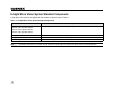
Legal Notices
The software described in this document is furnished under license, and may be used or copied only in accordance with the terms of such
license and with the inclusion of the copyright notice shown on this page. Neither the software, this document, nor any copies thereof may be
provided to, or otherwise made available to, anyone other than the licensee. Title to, and ownership of, this software remains with Cognex
Corporation or its licensor. Cognex Corporation assumes no responsibility for the use or reliability of its software on equipment that is not
supplied by Cognex Corporation. Cognex Corporation makes no warranties, either express or implied, regarding the described software, its
merchantability, non-infringement or its fitness for any particular purpose.
The information in this document is subject to change without notice and should not be construed as a commitment by Cognex Corporation.
Cognex Corporation is not responsible for any errors that may be present in either this document or the associated software.
Companies, names, and data used in examples herein are fictitious unless otherwise noted. No part of this document may be reproduced or
transmitted in any form or by any means, electronic or mechanical, for any purpose, nor transferred to any other media or language without the
written permission of Cognex Corporation.
Cognex P/N 597-0109-01
Copyright © 2008 Cognex Corporation. All Rights Reserved.
The hardware and portions of the software described in this document may be covered by one or more of the following U.S. patents (other U.S.
and foreign patents are pending):
Hardware
4,972,359; 5,526,050; 5,657,403; 5,793,899
Vision Tools
5,495,537; 5,548,326; 5,583,954; 5,602,937; 5,640,200; 5,717,785;
5,742,037; 5,751,853; 5,768,443; 5,796,868; 5,818,443; 5,825,483;
5,825,913; 5,845,007; 5,859,466; 5,872,870; 5,909,504
Cognex, Cognex, Vision for Industry, the In-Sight "crosshair" logo, and In-Sight are registered trademarks of Cognex Corporation.
VisionView and the Cognex logo are trademarks of Cognex Corporation.
i
ii
Regulations/Conformity
Declaration of Conformity
Cognex Corporation
One Vision Drive
Natick, MA 01760 USA
Manufacturer:
Declares this
-marked Machine Vision System Product
Product Number:
In-Sight Micro 1020/1050: P/N or Type 821-0002-1R
In-Sight Micro 1100/1110: P/N or Type 821-0002-1R
In-Sight Micro 1400/1410: P/N or Type 821-0002-1R
In-Sight Micro 1403/1413: P/N or Type 821-0003-1R
Complies With:
2004/108/EC Electromagnetic Compatibility Directive
Compliance Standards:
EN 55022:2006 Class A
EN 61000-6-2:2005
European Representative: Cognex France
Immeuble le Patio
104 avenue Albert 1er
92563 Rueil Malmaison
France
Safety and Regulatory
FCC
FCC Part 15, Class A
This device complies with Part 15 of the FCC Rules. Operation is subject to the following two conditions: (1) This device may not
cause harmful interference, and (2) this device must accept any interference received, including interference that may cause
undesired operation.
This equipment generates, uses, and can radiate radio frequency energy and, if not installed and used in accordance with the
instruction manual, may cause harmful interference to radio communications. Operation of this equipment in a residential area is
likely to cause harmful interference in which case the user will be required to correct the interference at their own expense.
NRTL
TUV SUD AM SCC/NRTL OSHA Scheme for UL/CAN 60950-1
CB
TUV SUD AM, IEC/EN 60950-1
Note:
For the most up-to-date regulations and conformity information, please refer to the In-Sight online support site:
http://cognexsensors.com/In-Sight.
iii
iv
Precautions
Observe these precautions when installing the sensor to reduce the risk of injury or equipment damage:
•
In-Sight Micro vision systems are intended to be supplied by a standard Class 2 Power over Ethernet (PoE) power supply. Any other
voltage creates a risk of fire or shock and can damage the sensor components.
•
To reduce the risk of damage or malfunction due to over-voltage, line noise, electrostatic discharge (ESD), power surges, or other
irregularities in the power supply, route all cables and wires away from high-voltage power sources.
•
Do not install In-Sight sensors where they are directly exposed to environmental hazards such as excessive heat, dust, moisture,
humidity, impact, vibration, corrosive substances, flammable substances, or static electricity.
•
Do not expose the CCD to laser light; CCDs can be damaged by direct, or reflected, laser light. If your application requires the use of
laser light that may strike the CCD, a lens filter at the corresponding laser's wavelength is recommended. Contact your local integrator
or application engineer for suggestions.
•
The In-Sight sensor does not contain user-serviceable parts. Do not make electrical or mechanical modifications to In-Sight sensor
components. Unauthorized modifications may void your warranty.
•
Changes or modifications not expressly approved by the party responsible for regulatory compliance could void the user’s authority to
operate the equipment.
v
vi
Table of Contents
Introduction
In-Sight Micro Vision System Overview ..................................................................................................................................... 1
In-Sight Support ......................................................................................................................................................................... 1
In-Sight Micro Vision System Standard Components ................................................................................................................ 2
Installing the Sensor
Connecting the In-Sight Micro Vision System ............................................................................................................................ 3
Install the Lens ................................................................................................................................................................ 4
Connect the I/O Cable (Optional) .................................................................................................................................... 5
Connect the PoE Cable................................................................................................................................................... 6
Specifications
General Specifications ............................................................................................................................................................... 9
I/O Specifications ..................................................................................................................................................................... 11
Acquisition Trigger Input................................................................................................................................................ 11
High-Speed Outputs...................................................................................................................................................... 13
PoE Cable Specifications .............................................................................................................................................. 18
I/O Cable Specifications ................................................................................................................................................ 19
In-Sight Dimensional Drawings ................................................................................................................................................ 20
In-Sight Mount Dimensions ...................................................................................................................................................... 21
Appendix A
Installing the Mounting Block.................................................................................................................................................... 23
Appendix B
Cleaning/Maintenance.............................................................................................................................................................. 25
Cleaning the Sensor Housing........................................................................................................................................ 25
Cleaning the CCD Window............................................................................................................................................ 25
vii
viii
Introduction
In-Sight Micro Vision System Overview
In-Sight® Micro vision systems are compact, network-ready machine vision sensors for automated inspection, measurement, identification and
robot guidance applications on the factory floor. For a list of all available sensors, refer to Table 1-1 on page 2.
All models are configured remotely over a network using an intuitive user interface. This interface allows remote monitoring of the sensor’s
operation during runtime. These sensors may also be controlled remotely to change settings and retrieve results.
This manual describes how to install the In-Sight Micro vision system.
In-Sight Support
Many information resources are available to assist you in using the sensor:
•
In-Sight®Explorer Help, an online HTML Help file provided on the In-Sight CD-ROM (for In-Sight Explorer software).
•
In-Sight computer-based tutorials provided on CD-ROM with selected In-Sight starter accessories kits.
•
The In-Sight online support: http://cognexsensors.com/In-Sight.
1
In-Sight Micro Vision System Standard Components
In-Sight Micro vision systems are shipped with the standard components listed in Table 1-1.
Table 1-1: In-Sight Micro Vision System Standard Components
Component
Description
Vision Sensor:
1020/1050: P/N or Type 821-0002-1R
1100/1110: P/N or Type 821-0002-1R
1400/1410: P/N or Type 821-0002-1R
1403/1413: P/N or Type 821-0003-1R
Provides image acquisition, vision processing, job storage, Ethernet connectivity and discrete I/O.
Mounting Screw Kit
Includes M3 screws for mounting the sensor (quantity 4).
Mounting Block
Optional block for securing the sensor to a mounting surface.
Extension Ring
A 5mm extension ring (for use with C-mount lenses).
Note:
2
The standard components do not include a Power over Ethernet (PoE) cable or I/O cable; these cables must be purchased separately.
Installing the Sensor
Connecting the In-Sight Micro Vision System
This section describes the connection of the sensor to its standard and optional components. For a complete list of options and accessories,
contact your Cognex sales representative.
Table 2-1: Sensor Connectors and Indicators
Connector/Indicator
Function
I/O Connector
Connects the I/O cable, which provides connections to the acquisition trigger input and high-speed outputs. Refer to
Table 3-5 on page 19.
PoE Connector
Connects the sensor to a network. The PoE connector provides power to the sensor and the Ethernet connection to
external network devices. Refer to Table 3-4 on page 18.
LED1
Green when active. User-configurable using Discrete Output Line 4 (Line 10 when using the CIO-WENET (750-341)
Ethernet I/O Expansion Module).
LED2
Red when active. User-configurable using Discrete Output Line 5 (Line 11 when using the CIO-WENET (750-341)
Ethernet I/O Expansion Module).
ENET
100-BaseT: Red when the sensor is receiving power during startup, momentarily switches to green when a network
connection is established, and then blinks green when network traffic is detected. If a network connection cannot be
established, the LED remains red.
10-BaseT: Red when the sensor is receiving power during startup, momentarily switches to green when a network
connection is established. The LED is solid green with red blinking when network traffic is detected. If a network
connection cannot be established, the LED remains red.
3
Install the Lens
Installing a lens allows you to see the sensor acquire live video images. The exact lens focal length needed depends on the working distance
and the field of view required for your machine vision application.
1.
Attach a CS-Mount or C-Mount (with 5mm extension ring) lens to the sensor (Figure 2-1).
Figure 2-1: Install the Lens
4
Installing the Sensor
Connect the I/O Cable (Optional)
The I/O connector supplies connections for the acquisition trigger and high speed inputs and outputs.
• The In-Sight sensor standard components do not include an I/O cable; this cable must be purchased separately.
Notes:
• Refer to the In-Sight® Explorer Help file for details on configuring the discrete input and output lines.
• Unused bare wires can be clipped short or tied back using a tie made of non-conductive material.
1.
Attach the M8 connector of the I/O cable to the sensor’s I/O connector.
2.
Connect the trigger and high speed I/O wires to an appropriate device (for example, a PLC, trigger sensor, strobe light, etc.).
HS OUT 0 (Brown)
HS OUT 1 (White)
TRIGGER+ (Blue)
TRIGGER- (Black)
COMMON (Gray)
Figure 2-2: Connect the I/O Cable
5
Connect the PoE Cable
The PoE connector provides the Ethernet connection for network communications and supplies power to the sensor.
Note:
1.
The In-Sight sensor standard components do not include a PoE cable; this cable must be purchased separately.
Attach the M12 connector of the PoE cable to the sensor’s PoE connector.
Figure 2-3: Connect the PoE Cable
6
Installing the Sensor
Option 1: Connecting to a Local PC, an Existing Network or an Ethernet I/O Expansion Module
In this configuration, the PoE injector supplies power to the sensor.
1.
Connect the RJ-45 connector of the PoE cable to the PoE injector’s POE OUT port.
2.
Connect an RJ-45 cable from the PoE injector’s ETH IN port to the PC, switch/router or Ethernet I/O expansion module, as applicable.
3.
Connect the 24VDC power supply to the PoE injector.
4.
Supply power to the 24VDC power supply.
Figure 2-4: Connected to a Local PC, an Existing Network or an Ethernet I/O Expansion Module
7
Option 2: Connecting to a Cognex VisionView™
In this configuration, the VisionView supplies power to the sensor.
1.
Connect the RJ-45 connector of the PoE cable to one of the VisionView Vision Sensor ports.
2.
Connect the 24VDC power supply to the VisionView.
3.
Supply power to the VisionView.
Note:
For more information, refer to the VisionView User Manual.
Figure 2-5: Connected to VisionView
8
Specifications
General Specifications
The following sections list general specifications for the In-Sight Micro vision systems.
Table 3-1: In-Sight Micro Vision System Specifications
Specification
In-Sight 1020/1050
In-Sight 1100/1110
In-Sight 1400/1410
In-Sight 1403/1413
Performance Class
Minimum Firmware Requirement
In-Sight version 4.1.0
Memory
Job/Program
64MB non-volatile flash memory; unlimited storage via remote network device.
Image
Processing
128MB
Sensor
1/3-inch CCD
1/1.8-inch CCD
Sensor
Properties
5.92mm diagonal, 7.4 x 7.4µm sq. pixels
8.8mm diagonal, 4.4 x 4.4µm sq.
pixels
Resolution
(pixels)
640 x 480
1600 x 1200
Electronic
Shutter Speed
16µs to 1000ms
27µs to 1000ms
Acquisition1
Rapid reset, progressive scan, full-frame integration.
Image
256 grey levels (8 bits/pixel)
Gain/Offset controlled by software.
60 full frames per second
Lens Type
CS-mount and C-mount (with 5mm extension, included).
Image
±0.127mm (0.005in), (both x and y) from lens C-mount axis to center of imager.
14 full frames per second
Repeatability2
I/O
Trigger
1 opto-isolated, acquisition trigger input.
Remote software commands via Ethernet.
Communications
Discrete Inputs
Eight inputs available when using the optional CIO-WENET (750-341) Ethernet I/O expansion module.
Discrete
Outputs
2 built-in, high-speed outputs.
Status LEDs
Network, 2 user configurable.
Network
1 Ethernet port, 10/100 BaseT MIDI-X. Supports DHCP (factory default), static and link-local IP address configuration.
Eight outputs available when using the optional CIO-WENET (750-341) Ethernet I/O expansion module.
9
Table 3-1: In-Sight Micro Vision System Specifications (Cont.)
Specification
Power
Mechanical
Environmental
In-Sight 1020/1050
In-Sight 1100/1110
In-Sight 1400/1410
Class
Class 2 Power over Ethernet (PoE) device.
Type
A and B.
Material
Die-cast zinc housing.
Finish
Painted.
Mounting
Four M3 threaded mounting holes (1/4 - 20 and M6 mounting holes also available on mounting block).
Dimensions
30mm (1.18in) x 30mm (1.18in) x 60mm (2.36in)
Weight
121g (4.27oz.) without mounting block.
146g (5.15oz.) with mounting block.
Temperature
0°C (32°F) to 45°C (113°F) (Operating), -30°C (-22°F) to 80°C (176°F) (Storage)
Humidity
90%, non-condensing (Operating and Storage)
Protection
IP51 with cables and lens attached.
Shock
80 G shock with 50 gram lens attached per IEC 68-2-27.
Vibration
10 G from 10-500 Hz with 50 gram lens attached per IEC 68-2-6.
Regulatory Compliance
In-Sight 1403/1413
CE, FCC, TUV SUD NRTL, RoHS
1. Maximum frames per second is job-dependent and based on the minimum exposure for a full image frame capture.
2. Expected repeatability between sensors. This equates to ~ ±17 pixels on a 640 x 480 resolution sensor and ~ ±29 pixels on a 1600 x 1200 resolution sensor.
10
Specifications
I/O Specifications
Cable and connector specifications and connection examples for the Acquisition Trigger input and the high-speed outputs are provided in the
following sections.
Acquisition Trigger Input
Table 3-2: Acquisition Trigger Input Specifications
Specification
Voltage
Current
Delay
Description
ON
20 to 28V (24V nominal)
OFF
0 to 3V (12V nominal threshold)
ON
2.2 to 3.3 mA
OFF
<308µA
Resistance
~9,000 Ohms
In-Sight Micro 1020, 1050, 1100,
1110, 1400, & 1410
62µs maximum latency between leading edge of trigger and start of acquisition. Input pulse should be minimum of 1 ms wide.
In-Sight Micro 1403 & 1413
80µs maximum latency between leading edge of trigger and start of acquisition. Input pulse should be minimum of 1 ms wide.
11
The acquisition trigger input on the sensor is opto-isolated. To trigger from an NPN (pull-down) type photo-detector or PLC output, connect pin
2 (TRG+) to +24V and connect pin 3 (TRG-) to the output of the detector. When the output turns ON, it pulls TRG- down to 0V, turning the optocoupler ON. To trigger from a PNP (pull-up) photo-detector or PLC output, connect pin 2 (TRG+) to the output of the detector and connect pin 3
(TRG-) to 0V. When the output turns ON, it pulls TRG+ up to 24V, turning the opto-coupler ON.
15K
+3.3V
4.22K
TRG-
1.4K
TRG+
4.22K
28V Max. Across input pins - Transition approx. 12V (Min).
Figure 3-1: Acquisition Trigger Input Schematic
12
Specifications
High-Speed Outputs
The In-Sight sensor features two built-in, high-speed outputs.
Table 3-3: High-Speed Output Specifications
Specification
Description
Voltage
28V maximum through external load.
Current
100mA maximum sink current.
OFF state leakage current 100µA maximum.
External load resistance 240 Ohms to 10K Ohms.
Each line rated at a maximum 100mA, protected against over-current, short circuit and transients from switching inductive loads.
High current inductive loads require external protection diode.
The high-speed outputs can be used as either NPN (pull-down) or PNP (pull-up) lines. For NPN lines, the external load should be connected
between the output and the positive supply voltage (<28V). The outputs pull down to less than 3V when ON, which causes current to flow
through the load. When the outputs are OFF, no current flows through the load.
Controller
Opto-isolators
ȍ
PTC
Fuse
ȍ
NPN OUT
OUT COMMON
Figure 3-2: NPN High-Speed Output Schematic
13
For PNP lines, the external load should be connected between the output and the negative supply voltage (0V). When connected to a 24VDC
power supply, the outputs pull up to greater than 21V when ON, and current flows through the load. When the outputs are OFF, no current flows
through the load.
Controller
Opto-isolators
OUT COMMON
ȍ
ȍ
PTC
Fuse
Figure 3-3: PNP High-Speed Output Schematic
14
PNP OUT
Specifications
Example 1
To connect the high-speed outputs to a relay, LED or similar load, connect the negative side of the load to the output and the positive side to
+24V. When the output switches on, the negative side of the load is pulled down to less than 3V, and 24V appears across the load. Use a
protection diode for a large inductive load, with the anode connected to the output and the cathode connected to +24V.
I/O Cable
HS OUT 0
HS OUT 1
TRIGGER+
TRIGGERCOMMON
GND
24VDC
HS OUT 0 - Brown
HS OUT 1 - White
Load
(Coil, Relay,
Pilot Light, etc.)
NOT TO EXCEED 100mA
Figure 3-4: High-Speed Output Connection Example 1
15
Example 2
To connect to an NPN-compatible PLC input, connect Output 0 or Output 1 directly to the PLC input. When enabled, the output pulls the PLC
input down to less than 3V.
I/O Cable
HS OUT 0
HS OUT 1
TRIGGER+
TRIGGERCOMMON
GND
24VDC
HS OUT 0 - Brown
HS OUT 1 - White
NPN PLC
NPN Compatible Input
GND
24VDC
Figure 3-5: High-Speed Output Connection Example 2
16
Specifications
Example 3
To connect to a PNP-compatible PLC input, connect Output 0 or Output 1 directly to the PLC input. When enabled, the output pulls the PLC
input up to greater than 21V.
I/O Cable
HS OUT 0
HS OUT 1
TRIGGER+
TRIGGERCOMMON
GND
24VDC
HS OUT 0 - Brown
HS OUT 1 - White
PNP PLC
PNP Compatible Input
GND
24VDC
Figure 3-6: High-Speed Output Connection Example 3
17
PoE Cable Specifications
The PoE cable provides the Ethernet connection for network communications and supplies power to the sensor.
Table 3-4: PoE Cable Pin-Out
1
8
7
6
5
2
P1
4
P2
3
Note:
18
Signal Name
P1 Pin#
P2 Pin#
Wire Color
TPO+/+48V (Mode A)
6
1
White/Orange
TPO-/+48V (Mode A)
4
2
Orange
TPI+/+48V RTN (Mode A)
5
3
White/Green
+48V (Mode B)
7
4
Blue
+48V (Mode B)
1
5
White/Blue
TPI-/+48V RTN (Mode A)
8
6
Green
+48V RTN (Mode B)
2
7
White/Brown
+48V RTN (Mode B)
3
8
Brown
The sensor’s standard components do not include a PoE cable; it must be purchased separately.
Specifications
I/O Cable Specifications
The I/O cable provides access to trigger and high-speed outputs.
Table 3-5: I/O Cable Pin-Out
2
4
1
3
P1
5
HS OUT 0
HS OUT 1
TRIGGER+
TRIGGERCOMMON
Notes:
Pin#
Signal Name
Wire Color
1
HS OUT 0
Brown
2
HS OUT 1
White
3
TRIGGER+
Blue
4
TRIGGER-
Black
5
COMMON
Gray
• The sensor’s standard components do not include an I/O cable; it must be purchased separately.
• Unused bare wires can be clipped short or tied back using a tie made of non-conductive material.
19
In-Sight Dimensional Drawings
Note:
All dimensions are in millimeters [inches].
60.0 2.36
30.0 1.18
OPTICAL
AXIS
70.1 2.76
12.53 .493
OPTICAL
AXIS
30.0 1.18
9.0 .35
OPTICAL
AXIS
21.2 .83
15.0 .59
10.0 .39
11.0 .43
47.3 1.86
19.0 .75
1.5 .06
11.0 .43
22.0 .87
2X M3
19.0 .75
OPTICAL
AXIS
4.5[.18]
OPTICAL
AXIS
2.53 .100
1. ALL DIMENSIONS ARE FOR
REFERENCE PURPOSES ONLY.
2. ALL SPECIFICATIONS MAY BE
CHANGED WITHOUT NOTICE.
2X M3
3.0[.12]
Figure 3-7: In-Sight Micro Vision System Dimensions
20
Specifications
In-Sight Mount Dimensions
Note:
All dimensions are in millimeters [inches]. Refer to Appendix A for installation instructions.
60.0 2.36
30.0 1.18
OPTICAL
AXIS
70.1 2.76
9.0 .35
12.53 .493
OPTICAL
AXIS
38.2 1.50
OPTICAL
AXIS
30.0 1.18
21.2 .83
11.0 .43
23.2 .91
19.7 .78
13.2 .52
6.4 .25 THRU
1/4-20 UNC - 2B
12.7[0.50]
1. ALL DIMENSIONS ARE FOR
REFERENCE PURPOSES ONLY.
OPTICAL
AXIS
2.53 .100
27.9 1.10
19.0 .75
2. ALL SPECIFICATIONS MAY BE
CHANGED WITHOUT NOTICE.
OPTICAL
AXIS
3X M6X1.0 - 6H
12.0[0.47]
22.0 .87
Figure 3-8: In-Sight Micro Vision System Dimensions (with Mounting Block)
21
22
Appendix A
Installing the Mounting Block
The sensor’s standard components include a mounting block to secure the sensor to a mounting surface.
Figure 4-1: Mounting Block Installation Diagram
1.
Align the mounting block with the mounting holes on the sensor.
2.
Insert the M3x6 (quantity 4) screws into the mounting holes and tighten the screws (maximum torque 8 ft.-lb.) using a 2.5mm Allen
wrench.
3.
Connect the I/O cable (optional) and PoE cable to the sensor.
23
24
Appendix B
Cleaning/Maintenance
Cleaning the Sensor Housing
To clean the outside of the sensor housing, use a small amount of mild detergent cleaner or isopropyl alcohol on a cleaning cloth. Do not pour
the cleaner directly onto the sensor housing.
Note:
Do not attempt to clean any In-Sight product with harsh or corrosive solvents, including Lye, methyl ethyl ketone (MEK) or gasoline.
Cleaning the CCD Window
To remove dust from the outside of the CCD window, use a pressurized air duster. The air must be free of oil, moisture or other contaminants
that could remain on the glass and possibly degrade the image. Do not touch the glass window. If oil/smudges still remain, clean the window
with a cotton bud using ethyl alcohol. Do not pour the alcohol directly on the window.
25
26
597-0109-01
Made in the U.S.A.