1
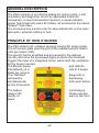
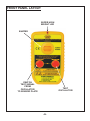
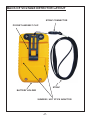
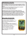
PERSONAL ELECTROCUTION
GUARD
AC VOLTAGE (50 or 60Hz)
INSTRUCTION MANUAL
TABLE OF CONTENTS
SAFETY RULES .....................................................
01
GENERAL DESCRIPTION .....................................
02
PRINCIPLE OF HOW IT WORKS ..........................
02
CHECK IT AND GET IT GOING .............................
03-04
Check the working of the PEG ...........................
03
Low battery detection and indication ..................
03
Sensitivity ...........................................................
03
Priority of functions - display and sound alerts ..
04
LOW VOLTAGE TESTING .....................................
05
FOR BEST RESULTS ............................................
05
FRONT PANEL LAYOUT ........................................
06
BACK OF PEG LAYOUT ........................................
07
PREPARATION FOR USE .....................................
08
CHECKING AND PROOFING THE TESTER ........
08
TYPICAL USES .....................................................
09
BROKEN WIRES IN CABLES ...............................
09
NON CONTACT ADVISE ......................................
09
LIMITATIONS OF THE PEG ..................................
10
LABORATORY AND FIELD TEST RESULTS .......
11
SPECIFICATIONS .................................................
12
LIMITED WARRANTY ...........................................
13-14
SAFETY RULES
The Personal Electrocution Guard (PEG) has been designed with
safety in mind. However, no design can completely protect against
incorrect use.
Electrical circuits are dangerous and lethal through lack of
caution or poor safety practice. Please follow safety rules to
reduce danger and practice safety.
You are advised to take note of the following important points;
• Read the User's manual carefully and completely before
using the tester. Fully understand the instructions before
using this product. Follow the instructions for every test.
Take all the necessary precautions. Do not exceed the
limits of this instrument.
• The PEG should never be in physical contact with any conductor
higher than 1kV. This is proximity detector. It is not a detector
which works by contact. As such, contact should be avoided.
• Always check that the PEG is working correctly before and after
the test (press both push button to verify the device is working
perfectly before using the testers to detect voltage and repeat
same after detection).
• Do not touch any exposed wiring, connections or other
"Live" parts of an electrical circuit.
• This instrument should only be used by a competent,
suitably trained person which understands fully this test
procedure. Personal working with High Voltage should be
trained regularly. Use Protective gear.
Caution, risk of electric shock.
Caution, refer to the user's manual.
-1-
GENERAL DESCRIPTION
The PEG consists of an internal pickup AC sensor plate, a test
(oscillator) and diagnostic circuit, an adjustable threshold
comparator, a sound annunciator (buzzer), a visual indicator
(super high bright led) and a 9V battery, all enclosed in the robust
"beeper" style case.
The enclosure has a built-in clip for easy attachment on the outer
garments / external clothing or belt.
PRINCIPLE OF HOW IT WORKS
The PEG detects AC voltages using its internal AC sensor plate.
The AC sensor plate picks up part of the radiated electric field in
volts per meter (V/M).
The electric field is amplified and processed by the internal
circuitry and once the processed signal is above the threshold,
triggers the input of a integrated circuit, which start the oscillators
for the buzzer and led.
The Buzzer beeps
and LED lits
intermittently at a
rate of 2 beeps
/flash per second.
The "Self-test"
diagnostic is
actioned by
depressing
simultaneously
both push button
on the front panel.
The battery
always ON.
priority of
panel.
monitoring is
Please see the
alert on the front
-2-
CHECK IT AND GET IT GOING
After inserting the battery, close the cover. The tester will be ON
automatically.
1- Check the working of the voltage detector
Once the battery has been inserted, wait for a few seconds.
If no beep and no flash occurs, press simultaneously the 2
push buttons.
While the 2 push buttons are pressed, the internal 50/60Hz
oscillator will start oscillating (generates test signal) and this
signal will be connected to the sensor.
While pressing the 2 push buttons, the buzzer and the
led will function at a rate of about 2 beep/flash per second.
That indicate proper operation of the tester.
Release the push buttons, and wait for about 30 seconds. If
there are no other beep/flashes, that mean everything is correct
and it is ready for use.
2- Low Battery detection and indication
When the battery becomes to low, a beep/flash will happen
about every 5 seconds, Replace the battery immediately.
3- Sensitivity
Covering the voltage detector with any kind of obstructive
material could affect its sensitivity. It is advised to wear it
outside clothing, clipped on the belt or on the pocket. Please
note that the enclosure is static sensitive and can become
charged and thus alarm may be triggered by excessive static.
-3-
4- Priority of functions - display and sound alerts
1-
= Voltage Detected
= First Priority
= the tester beeps and flashes twice per second.
2-
= Simulated Test = Voltage Detected
= Second Priority (identical to 1st priority)
= the tester beeps and flashes twice per second.
3-
= Battery Indication
= Third Priority
= the tester beeps and flashes every 5 seconds.
-4-
LOW VOLTAGE TESTING
Physical contact with electrical conductors is not necessary when
testing for Live Lines proximity.
This tester works by proximity.
Its sensor senses the radiated field which surrounds live
conductors.
It is recommended not to touch High Voltage wires with the PEG.
Radiated field strength increases with voltage and decreases
quickly with distance or earth shielding.
Detecting distance of a 240Vac single Live Wire is about 10cm.
FOR BEST RESULTS
The PEG should always be WORN ON THE OUTSIDE of any
clothing.
For example, clipped onto the pocket, belt or on the vehicle's
mirror.
The PEG could be sensitive to static build-up and may become
charged. In this case, this could trigger the alarm.
The PEG should be worn FACING THE DIRECTION OF
WALKING TOWARD THE SOURCE.
WHILE FACING THE SOURCE, THIS WOULD BE THE FRONT
OF YOUR BODY ( use the breast pocket ).
Always ensure that the alarm can be heard and seen (in case of
noisy environment, check the alarm sound again before use to
ensure you can be alarmed)
-5-
FRONT PANEL LAYOUT
SUPER HIGH
BRIGHT LED
BUZZER
SWITCH
TEST SIGNAL
FROM
OSCILLATOR
TO SENSOR PLATE
TEST
OSCILLATOR
-6-
BACK OF VOLTAGE DETECTOR LAYOUT
STRAP CONNECTOR
POCKET AND BELT CLIP
STRAP
BATTERY HOLDER
SUNRISE / HOT STICK ADAPTOR
-7-
PREPARATION FOR USE
When unpacked, the tester should be inspected for any visible
signs of damage, and the preliminary checks described (depress
both push button for proofing the unit) should be performed to
ensure that it is operating correctly.
If there is any sign of damage, or if the instrument does not
operate correctly, return it to your nearest supplier.
This instrument is powered by one 9V type battery. Use alkaline
for best results.
CHECKING AND PROOFING THE TESTER
Depress both push button simultaneously. The Buzzer will beep
and the LED will flash twice per second if everything is correct with
the proofing of the voltage detector.
-8-
TYPICAL USES
Workers Safety.
Emergency services protection (fireman, evacuation personal,
police, etc...)
Safely identify HV source while approaching it.
The user has the PEG clipped on his breast pocket while
working/walking in a electrical environment. The PEG will alert the
user of any HV source near by and therefore the user will be able
to take protective action before being close to the H.V.
Identify and check AC live cables.
Check and Detect Live High Voltage Cables.
Neon lightning servicing.
Tracing live wires.
Detecting of residual or induced voltages.
BROKEN WIRES IN CABLES
Faults in damaged flexible cables are found by applying low
voltage to each conductor in turn, earthing the remainder and
moving the tester along the cable until the change in condition is
obtained (flexible cables as used in mining and building industries
are readily repairable when the break in the cable is located).
NON CONTACT ADVISE
It is advised that the tester should not come into contact with
cables (kV) as this tester is merely an Non-Contact A.C. Proximity
Tester.
This advise is particularly useful to protect users which do not
respect protection and safety rules and who do not wear protective
gear.
Never work or be alone in the proximity of high voltage.
-9-
LIMITATIONS OF THE PEG
It is recommended that this tester is not used in H.V. Yards of
mixed voltages. In the presence of mixed voltages, the user
will not be able to pin point exactly which cable is the source
of H.V..
This tester has been designed to be used as a personal
safety proximity voltage detector alarm.
This is not a measuring instrument.
Problems can be arose when the tertiary circuit of a
275/133/11kV transformer is tested. The electric field of the
H.V. And M.V. Bus bars can trigger the detector when it is
about 3m above the ground (this is common with most of the
electric field PEG and the users should be aware of it).
The tester could pick up adjacent circuit to the one being
tested and indicates the wrong information to the user.
REPLACING THE BATTERY
The PEG has been designed to have
a super low current consumption.
One alkaline battery could last up to one
year or even more (Depending on the
battery energy).
Once the low battery alarm is announced
( beeps and flashes every 5 seconds),
the battery should be replaced Immediately.
The PEG uses one 9V battery.
Remove the battery cover. Ensure
polarity is respected and replace
with a new battery. (Photograph
shows cover removed and new
battery inserted.
-10-
LABORATORY AND FIELD TEST RESULTS
Expected Test Results (laboratory testing)
Expected sensitivity 150V/m
Minimum Detection Distance = MDD
Typical Detection Distance = TDD
SOURCE
MDD
240V
5cm
2.5kV
2m
5kV
2.5m
10kV
3.5m
15kV
5.25m
20kV
5.75m
25kV
6.75m
30kV
7.4m
35kV
8.25m
40kV
9m
45kV
9.5m
50kV
10m
TDD
5cm
3m
3.5m
4.75m
6.25m
6.5m
7.5m
8.25m
9m
9.5m
10m
10.5m
Typical Observation of Test Results made in the field.
SOURCE
MDD
TDD
240V
5cm ±20%
5cm ±20%
11kV
4m ±20%
5m ±20%
22kV
6.25m ±20%
7.25m ±20%
33kV
8m ±20%
8.75m ±20%
-11-
SPECIFICATIONS
ELECTRICAL
Detecting Range (Vac 40 to 70 Hz)
Selection Detects voltage from
variable from 80V (differs with type of source) to 44kV
Static can also trigger the voltage detector. Ensure the voltage
detector is not reacting to static but AC.
MECHANICAL
Case Height:
Case Width:
Case Depth:
Bump Test:
Vibration Test:
Drop Test:
Impact Test:
Weight:
115mm
67mm
30mm
IEC68-2-29
IEC1010, clause 8.3
IEC1010, clause 8.4
IEC1010, Clause 8.2
146g. with battery
ENVIRONMENTAL
Operating Temperature:
Storage Temperature:
Humidity:
Cold Temperature:
Dry Heat:
Damp Heat:
-15°C to + 55°C
-20°C to + 65°C
93% RH @ 40°C
IEC68-2-1
IEC68-2-2
IEC68-2-3
-12-
LIMITED WARRANTY
We warrant the product manufactured by us to be free from
defective material or factory workmanship and agree to repair or
replace this product which, under normal use and service, disclose
the defect to be the fault of our manufacturing, with no charge for
parts and service. If we are unable to repair or replace this product,
we will make a full refund of the purchase price.
Consult the user's manual for proper instruction regarding use of
this instrument.
Our obligation under this warranty is limited to repairing, replacing
or making refund of this test equipment which proves to be
defective within 24 months from the date of original purchase.
This warranty does not apply to any of our products which have
been repaired or altered by unauthorized persons in any way so as,
in our sole judgement, to injure their stability or reliability, or which
have been subject to misuse, abuse, misapplication, negligence or
accident or which have had the serial numbers altered, defaced or
removed.
Accessories, not of our manufacture used with this product, are not
covered by this warranty.
All warranties implied by law are hereby limited to a period of forty
eight months, and the provisions of the warranty are expressly in
lieu of any other warranties expressed or implied.
The purchaser agrees to assume all liability for any damages or
bodily injury which may result from the use or misuse of the product
by the purchaser, or it's user, his employees, or others, and the
remedies provided for in this warranty are expressly in lieu of any
other liability we may have including incidental or consequential
damages.
We reserve the right to discontinue models at any time, or change
Specification, price or design, without notice and without incurring
any obligation.
-13-
288