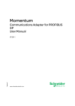
1
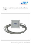
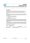
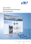
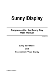
Measuring equipment for the Sunny Central
User manual
Version 1.0
SCMess-10:BE3406
SMA Technologie AG
Index
1
Explanation of the Symbols Used . . . . . . . . . . . . 5
2
Introduction . . . . . . . . . . . . . . . . . . . . . . . . . . . . . 6
3
Product Presentation . . . . . . . . . . . . . . . . . . . . . . 7
4
Electrical Wiring and Sensor Connection . . . . . . 10
5
Calibrating the Sunny Central Control . . . . . . . . 14
6
Overvoltage Protectors . . . . . . . . . . . . . . . . . . . 16
User manual
SCMess-10:BE3406
page 3
SMA Technologie AG
page 4
SCMess-10:BE3406
User manual
SMA Technologie AG
Explanation of the Symbols Used
1 Explanation of the Symbols Used
In order to ensure optimal use of these instructions, please note the following
explanation of symbols used.
This symbol indicates an example.
This symbol indicates a notice which, if not followed correctly, will make the
procedure or operation more difficult.
This symbol indicates a fact which, if not observed, could result in damage
to components or represent a danger to persons. Read these passages
especially carefully.
User Manual
SCMess-10:BE3406
Page 5
SMA Technologie AG
Introduction
2 Introduction
The Sunny Central enables the direct connection of analog and digital sensors for
determining environment data, such as global radiation or temperature.
The range of sensors comprises, among others, the following measurements:
Page 6
•
Irradiation sensor with integrated module temperature sensor RA 100 T
•
Temperature sensor for measuring the module temperature PT 100 M
•
Temperature sensor for measuring the ambient temperature PT 100 U
SCMess-10:BE3406
User Manual
SMA Technologie AG
Product Presentation
3 Product Presentation
3.1 Irradiation Sensor RA100 T
Description
Parameters
Voltage tolerance
max. 5 %
Temperature sensor
PT100
RPT100
PT100 basic series
Tolerance
class 1/3B
Dimensions
122 x 122 x 20 mm
Cable length
approx. 5 m (4 wires)
Calibration value
see type plate
Ambient temperature
-30° ... +50°C
Wire
function
Green
irradiation sensor +
White
irradiation sensor –
Yellow
PT 100 temperature sensor
Brown
PT 100 temperature sensor
User Manual
SCMess-10:BE3406
Page 7
SMA Technologie AG
Product Presentation
3.2 PT100 M Temperature Sensor
Description
Parameters
Connection
two-wire system up to 10 m
Mounting
installation using the provided dualcomponent thermal adhesive
RPT100
PT100 basic series
Tolerance
class 1/3B
Dimensions
30 x 6 x 6 mm
Cable length
approx. 2.5 m (2 wires)
Measuring range
20° - 110°C
Page 8
SCMess-10:BE3406
User Manual
SMA Technologie AG
Product Presentation
3.3 PT100 U Temperature Sensor
Description
Parameters
Connection
Four-wire system
Housing
IP 65
RPT100
PT100 basic series
Tolerance
class 1/3B
Dimensions
100 x 52 x 67 mm
Measuring range
30° - 80°C
User Manual
SCMess-10:BE3406
Page 9
SMA Technologie AG
Electrical Wiring and Sensor Connection
4 Electrical Wiring and Sensor Connection
The sensors are connected to the =Z5-X5 terminal.
4.1 RA100 T
Irradiation Sensor
In this case, an analog input is used as the voltage input. To do so, the positive pole of
the reference cell (green wire) is connected to terminal 5 or 7 and the negative pole of
the reference cell (white wire) is connected to terminal 6 or 8.
Irradiation sensor connection to "=Z5-X5"
Terminal 5
green wire (irradiation +)
Terminal 6
white wire (irradiation -)
or
Terminal 7
green wire (irradiation +)
Terminal 8
white wire (irradiation -)
PT100 Temperature Sensor
To also ensure the accuracy over greater distances, we recommend connecting the
PT100 sensor resistor in a four-wire system. For this purpose, the connecting wires of the
PT100 sensor resistor are duplicated directly next to the RA100 T sensor and thus a total
of 6 wires (2 wires for the irradiation sensor and 4 wires for the PT100 temperature
sensor) lead to the Sunny Central. The connection is established without using bridges
on the terminal strip in accordance with the following connection plan:
PT100 temperature sensor connection to "=Z5-X5" in a four-wire system
Terminal 1
yellow wire 1 (PT100 original wire)
Terminal 2
yellow wire 2 (PT100 duplicated wire)
Terminal 3
brown wire 1 (PT100 original wire)
Terminal 4
brown wire 2 (PT100 duplicated wire)
Page 10
SCMess-10:BE3406
User Manual
SMA Technologie AG
Electrical Wiring and Sensor Connection
A PT100 connection in a two-wire system
A PT100 connection in a four-wire system
PT100 temperature sensor connection to "=Z5-X5" in a two-wire system
Bridge terminal 1 with terminal 2
yellow wire (PT100 original wire)
Bridge terminal 3 with terminal 4
brown wire (PT100 original wire)
or
Terminal 5
yellow wire (PT100 original wire)
Terminal 6
brown wire (PT100 original wire)
or
Terminal 7
yellow wire (PT100 original wire)
Terminal 8
brown wire (PT100 original wire)
User Manual
SCMess-10:BE3406
Page 11
Electrical Wiring and Sensor Connection
SMA Technologie AG
4.2 PT100 M
The PT100 M temperature sensor consists of a PT100 sensor resistor that is embedded
in a metal tube. The sensor can be stuck directly to the back of the module using the
provided dual-component thermal adhesive and thus determine the module
temperature.
The connection is established using a 3-meter long cable in a two-wire system.
Here, we also recommend installing in a four-wire system.
PT100 temperature sensor connection to "=Z5-X5" in a four-wire system
Terminal 1
red wire 1 (PT100 original wire)
Terminal 2
red wire 2 (PT100 duplicated wire)
Terminal 3
white wire 1 (PT100 original wire)
Terminal 4
white wire 2 (PT100 duplicated wire)
PT100 temperature sensor connection to "=Z5-X5" in a two-wire system
Bridge terminal 1 with terminal 2
red wire (PT100 original wire)
Bridge terminal 3 with terminal 4
white wire (PT100 original wire)
or
Terminal 5
red wire (PT100 original wire)
Terminal 6
white wire (PT100 original wire)
or
Terminal 7
red wire (PT100 original wire)
Terminal 8
white wire (PT100 original wire)
Page 12
SCMess-10:BE3406
User Manual
SMA Technologie AG
Electrical Wiring and Sensor Connection
4.3 PT100 U
The PT100 U ambient temperature sensor consists of a PT100 sensor resistor that is
embedded in glass and is installed in an lP65 plastic housing. The ambient temperature
sensor is mounted using two mounting holes.
The PT100 U temperature sensor allows a measurement using either a two-wire or fourwire system. The connection cable is not included in the delivery and is routed into the
housing interior through a PG screw fitting.
Here, we also recommend installing in a four-wire system.
PT100 temperature sensor connection to "=Z5-X5" in a four-wire system
Terminal 1
terminal 14 on the sensor
Terminal 2
terminal 12 on the sensor
Terminal 3
terminal 13 on the sensor
Terminal 4
terminal 11 on the sensor
PT100 temperature sensor connection to "=Z5-X5" in a two-wire system
Bridge terminal 1 with terminal 2
terminal 12 on the sensor
Bridge terminal 3 with terminal 4
terminal 11 on the sensor
or
Terminal 5
terminal 12 on the sensor
Terminal 6
terminal 11 on the sensor
or
Terminal 7
terminal 12 on the sensor
Terminal 8
terminal 11 on the sensor
User Manual
SCMess-10:BE3406
Page 13
Calibrating the Sunny Central Control
SMA Technologie AG
5 Calibrating the Sunny Central Control
5.1 General Information
To properly calibrate the data logger for the irradiation sensor, the analog measuring
channels are programmed directly on the Sunny Central Control in the menu item "Setup…Interfaces…Analog In".
To calibrate the Sunny Central Control, the voltage value specified on the
type plate of the RA100 T sensor is required for an irradiation of 1000 W/
m². Please take note of this before installing the sensor!
5.2 RA100 T
Since the RA100 T consists of two sensors (irradiation and temperature), two sensors
must be programmed at this point:
Irradiation Sensor
A suitable measuring range must first be set in the first line under the "Function" column.
In case of the irradiation sensor in the RA100 T, the measurement tolerance range
would be ± 500 mV.
The name of the channel can be precisely defined in the next line (e.g. irradiation).
The measurement unit of the channel can be specified in the third line (here: W/m²).
The gain V is calculated from the value specified on the type plate for the measurement
voltage at 1000 W/m² and at 25°C as follows:
V = 1000 / measurement voltage at 1000 W/m²
The value for the offset is 0.
PT100 Temperature Sensor
The suitable temperature unit must first be set in the first line under the "Function" column.
In case of the temperature sensor of the RA100 T, that would be °C.
The name of the channel can be precisely defined in the next line (e.g. module
temperature).
The gain and offset do not require calculating.
Page 14
SCMess-10:BE3406
User Manual
SMA Technologie AG
Calibrating the Sunny Central Control
5.3 PT100 U
PT100 Temperature Sensor
The suitable temperature unit must first be set in the first line under the "Function" column.
In case of the temperature sensor of the RA100 T, that would be °C.
The name of the channel can be precisely defined in the next line (e.g. module
temperature).
The gain and offset do not require calculating.
5.4 PT100 M
PT100 Temperature Sensor
The suitable temperature unit must first be set in the first line under the "Function" column.
In case of the temperature sensor of the RA100 T, that would be °C.
The name of the channel can be precisely defined in the next line (e.g. module
temperature).
The gain and offset do not require calculating.
User Manual
SCMess-10:BE3406
Page 15
Overvoltage Protectors
SMA Technologie AG
6 Overvoltage Protectors
To protect the Sunny Central against external overvoltage, the sensors should be
connected using overvoltage protectors. Overvoltage protectors can be ordered
optionally.
We recommend the following overvoltage protectors.
PT 100
BLITZREDUCTOR CT
BCT MOD BE 5
DEHN item no.
919 506 + 919 620
Analog Signals
BLITZREDUCTOR CT
BCT MOD BD 30
DEHN item no.
919 506 + 919 644
Page 16
SCMess-10:BE3406
User Manual
SMA Technologie AG
User Manual
Overvoltage Protectors
SCMess-10:BE3406
Page 17
Legal Restrictions
SMA Technologie AG
The information contained in this document is the property of SMA Technologie AG. Publishing its content,
either partially or in full, requires the written permision of SMA Technologie AG. Any internal company copying
of the document for the purposes of evaluating the product or its correct implementation is allowed and does
not require permission.
Exclusion of liability
The general terms and conditions of delivery of SMA Technologie AG shall apply.
The content of these documents is continually checked and amended, where necessary. However,
discrepancies cannot be excluded. No guarantee is made for the completeness of these documents. The latest
version is available on the Internet at www.SMA.de or from the usual sales channels.
Guarantee or liability claims for damages of any kind are exlcuded if they are caused by one or more of the
following:
• Improper or inappropriate use of the product
• Operating the product in an unintended environment
• Operating the product whilst ignoring relevant, statutory safety regulations in the deployment location
• Ignoring safety warnings and instructions contained in all documents relevant to the product
• Operating the product under incorrect safety or protection conditions
• Altering the product or supplied software without authority
• The product malfunctions due to operating attached or neighboring devices beyond statutory limit values
• In case of unforeseen calamity or force majeure
Software licensing
The use of supplied software produced by SMA Technologie AG is subject to the following conditions:
This software may be copied for internal company purposes and may be installed on any number of
computers. Supplied source codes may be changed or adapted for internal company purposes on your own
responsibility. Drivers may also be transferred to other operating systems. Source codes may only be published
with the written permission of SMA Technologie AG. Sub-licensing of software is not permissible.
Limitation of liability: SMA Technologie AG rejects any liability for direct or indirect damages arising from the
use of software developed by SMA Technologie AG. This also applies to the provision or non-provision of
support activities.
Supplied software not developed by SMA Technologie AG is subject to the respective licensing and liability
agreements of the manufacturer.
Trademarks
All trademarks are recognized even if these are not marked separately. Missing designations do not mean that
a product or brand is not a registered trademark.
SMA Technologie AG
Hannoversche Straße 1-5
34266 Niestetal
Germany
Tel. +49 561 9522-0
Fax +49 561 9522-100
www.SMA.de
E-mail: [email protected]
© 2005 SMA Technologie AG. All rights reserved.
Page 18
SCMess-10:BE3406
User manual
Sales
Solar Technology
www.SMA.de
SMA Technologie AG
Hannoversche Strasse 1–5
34266 Niestetal, Germany
Tel. : +49 561 9522 4000
Fax: +49 561 9522 4040
E-Mail: [email protected]
Freecall: +800 SUNNYBOY
Freecall: +800 7 8 6 6 9 2 6 9
Innovation in Systems Technology
for the Success of Photovoltaics