1
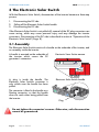
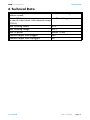
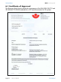
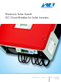
Electronic Solar Switch
DC Circuit Breaker for Solar Inverters
User Manual
Version 1.1
ESS-11:FE0307
TBE-ESS
SMA Technologie AG
Table of Contents
Table of Contents
1
2
3
Explanation of the Symbols Used . . . . . . . . . . . . . . . . 5
Safety Instructions . . . . . . . . . . . . . . . . . . . . . . . . . . . 5
The Electronic Solar Switch. . . . . . . . . . . . . . . . . . . . . 6
3.1
Assembly . . . . . . . . . . . . . . . . . . . . . . . . . . . . . . . . . . . . . . . 6
3.2
Installing the Inverter . . . . . . . . . . . . . . . . . . . . . . . . . . . . . . . 7
3.2.1
Minimum Clearance . . . . . . . . . . . . . . . . . . . . . . . . . . . . 7
4
Operation of the Electronic Solar Switch . . . . . . . . . . . 8
4.1
4.2
5
6
Connecting the DC Side . . . . . . . . . . . . . . . . . . . . . . . . . . . . . 8
Disconnecting the Inverter . . . . . . . . . . . . . . . . . . . . . . . . . . . 9
Inspection . . . . . . . . . . . . . . . . . . . . . . . . . . . . . . . . 10
Technical Data . . . . . . . . . . . . . . . . . . . . . . . . . . . . 11
6.1
7
8
Certificate of Approval . . . . . . . . . . . . . . . . . . . . . . . . . . . . .12
Contact . . . . . . . . . . . . . . . . . . . . . . . . . . . . . . . . . . 13
Glossary . . . . . . . . . . . . . . . . . . . . . . . . . . . . . . . . . 14
User Manual
ESS-11:FE0307
Page 3
Table of Contents
Page 4
ESS-11:FE0307
SMA Technologie AG
User Manual
SMA Technologie AG
Explanation of the Symbols Used
1 Explanation of the Symbols Used
This symbol indicates a fact which, if not observed, could result in
damage to components or represent a danger to persons. Read
these passages especially carefully.
This symbol indicates a fact that is important for optimum operation of the
product. Read these sections carefully to ensure this.
2 Safety Instructions
Any work on the inverter with the cover removed must be carried
out by a qualified electrician! High voltages are present in the
device. Before opening the inverter, the AC and DC voltages must
be disconnected from it, and it must be ensured that the capacitors
are discharged.
Read the inverter's installation guide. If you need to open or
perform maintenance work on the inverter, observe all
instructions and safety warnings.
Once the handle of the Electronic Solar Switch has been pulled out,
the inverter provides protection degree IP21. The inverter is no
longer protected against water and foreign objects.
If you require any information, please call the Sunny Boy Hotline:
+49 (561) 95 22 - 499
User Manual
ESS-11:FE0307
Page 5
SMA Technologie AG
The Electronic Solar Switch
3 The Electronic Solar Switch
With the Electronic Solar Switch, disconnection of the inverter becomes a three-step
process.
1.
Disconnecting the DC side
2.
Pulling off the Electronic Solar Switch handle
3.
Disconnecting the DC side
If the Electronic Solar Switch is not pulled off, removal of the DC plug connectors can
cause arcing, which may cause personal injury and may damage the inverter
connectors. Disconnection of the DC side is described in section 4 "Operation of the
Electronic Solar Switch" (Page 8).
3.1 Assembly
The Electronic Solar Switch consists of a handle on the underside of the inverter, and
an assembly inside the inverter.
A handle is mounted on the underside of
the inverter which covers the PV
generator's connectors.
Electronic Solar Switch handle
A plug is inside the handle. The
Electronic Solar Switch's connector is
only visible once the handle has been
pulled.
Electronic Solar Switch handle
The connector is fitted in the handle as a
floating connector, so that the handle
does not catch when being pulled from
the inverter.
Plug
Do not tighten the connector's screws. Otherwise, safe disconnection
cannot be guaranteed.
Page 6
ESS-11:FE0307
User Manual
SMA Technologie AG
The Electronic Solar Switch
3.2 Installing the Inverter
When installing the inverter, be sure to observe all instructions in the inverter's
installation guide! The special features relating to the installation with an
Electronic Solar Switch are described in these instructions.
3.2.1 Minimum Clearance
When choosing the installation location, ensure there is enough space for heat to
dissipate! Under normal conditions, the following guidelines should be followed to
provide enough clearance around the inverter:
Minimum clearance
Sunny Boy
Sunny Mini Central
Sides
20 cm
30 cm
Top
20 cm
30 cm
Underneath
50 cm
50 cm
Front
5 cm
5 cm
Be sure to leave enough free space underneath the inverter (recommended is:
50 cm), so that the Electronic Solar Switch can be pulled down safely!
User Manual
ESS-11:FE0307
Page 7
Operation of the Electronic Solar Switch
SMA Technologie AG
4 Operation of the Electronic Solar Switch
4.1 Connecting the DC Side
To connect the PV generator to the inverter, proceed as follows:
1.
Check the plug in the Electronic Solar Switch’s handle for any
significant loss of contact material (see section 5 "Inspection" (Page
10)).
2.
Plug the DC plugs into the device’s sockets.
Make sure the plug connectors have the correct
polarity.
3.
Close the unused DC input sockets.
The caps required for this purpose are included with
the inverter upon delivery.
4.
Attach the handle of the Electronic Solar
Switch.
Insert the handle once more into the Electronic
Solar Switch’s socket in the inverter.
The Electronic Solar Switch can become
damaged if it has not been attached
properly. The handle must be firmly
attached to the Electronic Solar
Switch's socket, and rest against the
housing. Check that the handle is
positioned
correctly
before
recommissioning the inverter.
5.
Switch the supply line circuit breaker to the "on"
position.
The inverter LEDs will glow if the PV generator is
ready for operation.
Page 8
ESS-11:FE0307
User Manual
SMA Technologie AG
Operation of the Electronic Solar Switch
4.2 Disconnecting the Inverter
Disconnecting the inverter is a three-step process. When disconnecting the inverter,
proceed as follows:
1.
Disconnect the AC side.
Switch the supply line circuit breaker to the "off" position.
2.
Remove the Electronic Solar Switch.
Pull the handle of the Electronic Solar Switch off the
inverter. Be sure to pull the handle downwards and
slightly towards the wall. There is a contact in the
middle that automatically starts the switching
process when the handle is pulled.
3.
Remove the PV plug connectors from the
inverter.
Immediately after you have removed the handle,
you must remove the DC plug connectors from the
inverter. The plugs must be removed to guarantee
the safe disconnection of the inverter from the PV
generator.
Make sure that no voltage is present at the inverter before
opening or working on it.
User Manual
ESS-11:FE0307
Page 9
SMA Technologie AG
Inspection
5 Inspection
You should always check the Electronic Solar Switch for any wear before using it
again. To do this, inspect the contacts of the integrated plug in the Electronic Solar
Switch handle. The plug consists of two plastic legs, each with contacts consisting of
two metal tongues.
Metal tongues
The metal tongues will show signs of wear when frequently used. This is completely
normal. Normally, the amount of wear is very small and the lifetime is
correspondingly long. The first signs of wear can be recognized by a brown
discoloration. If the metal tongues on either of the two plastic legs are completely
worn out (see figure below), then the Electronic Solar Switch can no longer safely
disconnect the DC side. Replacements for damaged Electronic Solar Switch handles
are available from SMA.
Worn-out metal tongues
Page 10
ESS-11:FE0307
User Manual
SMA Technologie AG
Technical Data
6 Technical Data
Mechanical lifetime
(without current):
min. 1,000 switching processes
Electrical lifetime
min. 50 switching processes
(in case of a short circuit, with a nominal current
of 30 A):
Max. switching current
30 A
Max. switching voltage
800 V
Max. PV power
approx. 10 kW
Protection degree when plugged
IP65
Protection degree when unplugged
IP21
User Manual
ESS-11:FE0307
Page 11
Technical Data
SMA Technologie AG
6.1 Certificate of Approval
The Electronic Solar Switch satisfies the requirements of the DIN VDE 0100-712 and
IEC 60364-7-712:2002 standards for a DC load disconnector for PV systems.
Page 12
ESS-11:FE0307
User Manual
SMA Technologie AG
Contact
7 Contact
If you have any questions or technical problems concerning the Electronic Solar
Switch, contact our hotline. Please have the following information available when
you contact SMA:
• Inverter type
• Type and number of modules connected
• Communication method
• Inverter's serial number
• Inverter's blink code or display
Address:
SMA Technologie AG
Hannoversche Strasse 1 - 5
34266 Niestetal
Germany
Tel.:
+49 (561) 95 22 - 499
Fax:
+49 (561) 95 22 - 4699
[email protected]
www.SMA.de
User Manual
ESS-11:FE0307
Page 13
SMA Technologie AG
Glossary
8 Glossary
AC
Abbreviation for "Alternating Current"
Capacitor
The Latin term is "condensus", meaning "tightly compact", referring to charges.
A capacitor is an electrical component for storing electrical energy in an electric field.
DC
Abbreviation for "Direct Current"
Inverter
A device for converting the direct current (DC) from the PV generator into alternating
current (AC), which is used by most normal household devices, especially for feeding
energy into an existing supply grid.
IP
Abbreviation for "Ingress Protection"
IP is a degree of protection. The degree of protection is an indicator of the suitability
of electrical equipment for various ambient conditions. The first digit which follows
the IP indicates protection against foreign objects, the second indicates protection
against water. The higher these numbers are, the better the inverter's protection.
Line circuit breaker
A line circuit breaker is an overcurrent protection device in an electrical installation.
It protects cables against damage caused by excessive heat which arises when
current is too high.
PV
Abbreviation for "photovoltaic", describes the conversion of solar energy into
electrical energy.
PV generator
Technical device for the conversion of solar energy into electrical energy. This
normally refers to all installed and electrically connected solar modules in a PV
system.
PV system
Describes the complete collection of components needed for the acquisition and
utilization of solar energy. As well as the PV-generator, this also includes the inverters
in the case of grid-connected systems.
Page 14
ESS-11:FE0307
User Manual
SMA Technologie AG
Glossary
Solar cell
An electronic component which generates electrical energy when irradiated with
sunlight. Since the voltage produced by a single solar cell is very small (approx. 0.5
V), several solar cells are combined to form a solar module. The most common
material presently used for solar cells is silicon, which is manufactured in different
forms (monocrystalline, polycrystalline, amorphous). In addition to different
mechanical variations, which are usually designed to increase the level of efficiency,
completely new materials are currently being tested (cadmium telluride, cadmium
indium sulphide, titanium dioxide and many others).
Solar module
A collection of solar cells in a housing that protects the sensitive cells from mechanical
stresses and allows easy installation.
User Manual
ESS-11:FE0307
Page 15
SMA Technologie AG
Glossary
Page 16
ESS-11:FE0307
User Manual
SMA Technologie AG
Sales
Solar Technology
www.SMA.de
SMA Technologie AG
Hannoversche Strasse 1–5
34266 Niestetal, Germany
Tel. : +49 561 9522 4000
Fax: +49 561 9522 4040
E-mail: [email protected]
Freecall: +800 SUNNYBOY
Freecall: +800 7 8 6 6 9 2 6 9
SMA America, Inc.
SMA Ibérica Tecnología Solar, S.L.
Grass Valley, California, USA
Barcelona, Spain
E-mail: [email protected]
E-mail: [email protected]
SMA Solar Technology China
SMA Italia S.r.l.
Beijing, P.R. China
Milan, Italy
E-mail: [email protected]
E-mail: [email protected]
SMA Technology Korea Co., Ltd.
Seoul, Korea
E-mail: [email protected]
Seite 18
ESS-11:FE0307
Innovation in Systems Technology
for the Success of Photovoltaics
User Manual