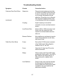
1
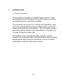
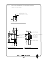
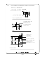
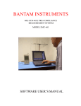
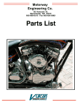
TABLE OF CONTENTS
Section
1.
INTRODUCTION
1.1
1.2
1.3
1.4
2.
INSTALLATION
2.1
2.2
2.3
2.4
2.5
3.
Product Overview
Teller Terminal Specification
Customer Terminal Specification
General Specification
Unpacking Instructions
Site Requirements
Installation Procedure
Wiring Diagrams
Installation Drawings
OPERATION
3.1
Switches and Indicators
3.1.1
3.1.2
3.1.3
3.1.4
3.1.5
3.1.6
3.1.7
3.1.8
3.1.9
3.1.10
Send Switch
Home Switch
Door Switch
Tset Switch
Send LED
Home LED
Customer Door Open LED
Customer Door Closed LED
Power Switch
Customer Safety Switch
I
Operating Instructions
PNEUMATIC
TUBE SYSTEM
MODEL 3000
TABLE OF CONTENTS (continued)
Section
3.2
Functions
3.2.1
3.2.2
3.2.3
3.2.4
3.2.5
3.2.6
3.2.7
3.3
4.
Sequence of Operation
MAINTENANCE
4.1
4.2
5.
Send
Home
Door
Tset
Customer Send
Recall in Flight
Shutdown
Cleaning
Preventative Maintenance
SERVICE
5.1
5.2
5.3
5.4
5.5
5.6
5.7
5.8
Fault Analysis
Troubleshooting Indicators for Customer P.C.B. and
Teller pushbutton P.C.B.
Troubleshooting indicators for Teller Terminal
Control P.C.B.
Troubleshooting Guide
Teller terminal P.C.B. schematic
Customer terminal P.C.B. schematic
Teller terminal detail
Customer terminal detail
II
DISCLAIMER
The material in this manual is for information purposes only. The
contents and the product described are subject to change without notice.
The manufacturer makes no representations or warranties with respect to
this manual. This product was designed for certain applications only. It
may not be modified and/or used for any applications other than that which it
was designed. The design specifications of the product described herein is
subject to change without notice. The manufacturer reserves the right to
make such changes without incurring any obligation to make them in units
previously sold. Differences between the unit you received and the views
contained herein are the result of design improvement and/or the addition of
options as specified.
WARNINGS
Caution:
If not properly installed, operated and maintained, the use
of this equipment presents the possibility of personal
injury or property damage. Before use, all persons who will
install, operate or maintain this product should read this
manual thoroughly. For safe, dependable performance,
follow all instructions and recommendations contained
herein.
Caution:
To prevent fire or shock, do not expose this product to rain
or any type of moisture.
Caution:
Keep hands clear of moving parts.
Caution:
Always unplug unit from power source prior to cleaning or
servicing unit.
III
1
INTRODUCTION
1.1 Product overview
This pneumatic tube system is a durable, field proven unit. It has
been designed to provide easy access by both customer and teller,
and reliable operation under harsh conditions.
This pneumatic tube system is for overhead tube applications using
the proven pull-both-directions method. Blowers are located in the
canopy and insulated for quiet operation. This unit employs elevator
style carrier delivery using an open frame platform on the teller end
that does not block the tellers view.
The standard unit is constructed of quality materials, including
extensive use of stainless steel on external surfaces and zinc plating
and galvanized steel for internal components. The unit is finished
using attractive black trim and custom overlays.
1-1
1.2
TELLER TERMINAL SPECIFICATIONS
MODEL 3100 TELLER UNIT
WIRE ACCESS (2 PL)
MOUNTING BOLT (3 PL)
5"
3
10 "
4
LEFT SIDE ELEVATION
1
1 "
4
3
7 "
8
WALL MOUNT
BRACKET
CARRIER PAD
7
1 "
8
24"
3
15 "
4
1
14 "
2
5"
13"
1
40 "
2
37"
1
3 "
2
PLAN
3
15 "
4
3
25 "
4
24"
1
9 "
8
SERVICE PANEL
"T-SET" SWITCH (HIDDEN)
SEND SWITCH
HOME SWITCH
DOOR SWITCH
POWER SWITCH
3
8 "
8
3
7 "
8
FRONT ELEVATION
(SHOWN WITH ELEVATOR PLATFORM UP)
CUSTOMER TERMINAL SPECIFICATIONS
MODEL 3200 CUSTOMER UNIT
5" SQ. CUTOUT FOR CONDUIT
CUSTOMER UNIT OUTLINE
5"
PLAN
1
2 "
2
5"
BASE MOUNTING BOLT (4 PL)
3"
(MOUNTING BASE)
PLAN
PENETRATION FOR
OPTIONAL OVERHEAD
CONDUIT (2 PL)
1 1/2"
3"
10"
3"
OVERHEAD CARRIER TUBE
2"
3
13 "
4
1
5 "
4
CAMERA PORT
(OPTIONAL)
SEND BUTTON
TELLER CALL BUTTON
39"
5
35 "
8
3
31 "
4
28"
7
25 "
8
1.3
AUDIO (SPEAKER/MIC)
CARRIER DEPOSIT
MOUNTING BOLT (4 PL)
20"
FRONT ELEVATION
1.4 Specifications
Power Requirements:
Power Consumption
Kiosk:
Blowers:
120 VAC 5-/60 Hz.
2 Amps
9 Amps ea.
Maximum package weight: Coins not recommended, otherwise
limited only by space in carrier.
Maximum carrier velocity:
40 feet per second
1-4
2
INSTALLATION
2.1 Unpacking and Inspection
Open shipping carton and remove the contents.
The carton should contain the following items:
1 ea.
1 ea.
1 ea.
1 ea.
2 ea.
2 ea.
2 ea.
2 ea.
1 ea.
1 ea.
1 ea.
Customer Unit
Customer Unit base
Teller Unit
Teller Unit Mounting bracket
Carriers
Steel radius w/port
Blower assembly
Blower hose
User Manual
Clear butyrate tubing 10’ Stick
Hardware Kit:
1 ea.
Butyrate/steel transition coupling
4 ea.
Hose Clamp
3 ea.
Bolt, hex head, 1/2-13 x 1”
4 ea.
Lag Screw, hex head, 1/2” x 2”
10 ea.
Flatwasher, 1/2”
4 ea.
Bolt, Hex head, 3/8-16 x 3/4”
4 ea.
Bolt, Hex head, 1/4-20 x 3/4”
4 ea.
Wedge Anchor, 3/8” x 2 3/4”
4 ea.
Lockwasher, split ring, 1/4”
4 ea.
Flatwasher, 1/4”
2-1
2.2 Site Requirements
The pneumatic tube system can be installed in most existing drive thru
locations. Adequate support structure is required to support the pneumatic
tube and blower packs above the drive thru. It is recommended that the
structure be covered to protect the blowers and the customer kiosk from
the weather. In the event that the blowers are mounted above the canopy, a
weatherproof housing must be provided.
Electrical power can be run underground or overhead. Underground
installations require 4 ea. 3/4” conduits for maximum utilization of optional
items, including CCTV cameras and heater.
Overhead power applications use 2 ea. 3/4” conduits. One for 115 VAC
power and the other for control, cctv, audio, low voltage power. Each blower
pack must be supplied with 115 VAC power by means of a junction box and
flex conduit to the blower pack.
each lane must have 1 20 amp circuit for the customer kiosk and 1 30 amp
circuit feeding two blower packs.
Note:
Reference section 2.5 for the Installation Drawing.
2-2
2.3 Installation Procedure
The teller unit is installed by mounting the hanging bracket on the wall above
the window. The G.C. should provide a 12” header capable of supporting
the weight of the teller unit to secure the bracket to the wall. The teller unit is
the attached to the bracket using supplied hardware.
The customer unit base is anchored to the island using 3/8” wedge
anchors. The base is positioned such that the 4 conduits are accessible
through the 5” square cutout in the base. The base is leveled using leveler
screws then secured using the anchor bolts.
The customer unit is then lowered into place onto the mount and secured
using supplied hardware.
The steel tubing is cut and fit using standard fitting practices.
Joints should be secured by welding then covered with heat shrink sleeve
to prevent vacuum loss. Tubing should be braced to prevent excessive
movement and possible stresses to joints.
Blower packs are mounted near the radii above each end. The may be
attached to any surface that will support their weight. Since many mounting
options are possible, Mounting hardware is not supplied for the blower
packs.
Wiring of the units is covered in section 2.4, page 2-4 of this manual.
2-3
3
OPERATION
3.1
Switches and Indicators
3.1.1
Send Switch
The send switch located on the
teller control panel initiates a send cycle any time the
system is not in the middle of a cycle. Regardless of
the position of either door or the carrier.
3.1.2
Home Switch
The home switch located on the
teller control panel initiates a home cycle any time it is
pushed. Even if the system is in the middle of a cycle,
and regardless of the position of any doors or the carrier
3.1.3
Door Switch
The door switch located on the
teller control panel changes the current position of
the customer door. This button is only active when no
other cycles are active.
3.1.4
Tset Switch
The Tset switch located on the
teller control panel but not shown on the front overlay
initiates a travel time set sequence. This process is
described further in section 3.2.4 of this manual.
3.1.5
Send LED
The send LED, located on the
teller control panel above the send switch indicates
that the carrier is being sent to the customer unit.
3.1.6
Home LED
The home LED, located on the
teller control panel above the home switch indicates
that the carrier is coming into the teller unit.
3.1.7
Customer Door Open LED Located on the
teller control panel above the door switch indicates
that the customer door open limit switch is pressed.
3-1
3.1.8
Customer Door Closed LED Located on the
teller control panel above the door switch indicates
that the customer door closed limit switch is
pressed.
3.1.9
Power Switch
The power switch located on the
bottom of the teller unit, Turns power off to the teller
unit. This switch does not turn power off to the entire
system. Main power is inside the customer unit.
3.1.10
Customer Safety Switch
The customer safety
switch, located across the top of the carrier deposit
chamber, when pressed, causes the customer door
to fully open and remain in that position until the teller
presses the send, home or door button.
3.1.11
Customer Send Switch
The customer send
switch, located on the front of the customer unit,
initiates a home cycle only upon the successful
completion of a teller send cycle.
3.1.12
Call Switch
The call switch, located on the front
of the customer unit, Is part of the audio interface
provided on the customer unit circuit board. Pressing
this switch generates a call tone on the connected
audio system.
3-2
3.2
Functions
3.2.1 Send
The send function is used to move the carrier
from the teller position to the customer position. When
this switch is pressed, the control checks the position of
the customer door. If the door is not closed, a signal is
generated to close it. Next, the position of the teller
elevator is checked, if it is not fully open, the door is
closed then opened halfway, if the door is fully open, the
door closes half way. Next, the send blower, located over
the customer unit comes on pulling the carrier to the
outside radius, the carrier then floats down to the customer
unit. When the send blower time completes, the outside
door opens then the teller door closes. This completes
the send cycle.
3.2.2 Home
The home function is used to move the carrier
from the customer end to the teller end. When this switch
is pressed, The teller door is closed if it not already
closed. Next, The customer door is checked. if it is
closed, it is opened halfway. If it is open, it is closed
halfway. Next, the home blower is turned on. The carrier
moves to the radius above the teller unit from there, it
floats down to the teller unit. When the home blower timer
completes, the teller door is opened then the customer
door is closed. This completes the home cycle
3.2.3 Door
The door function is used to change the
position of the outside door. If the door is closed and the
customer door closed LED on the teller control panel is lit,
The door will open when the switch is pressed, otherwise,
the door will close when pressed. When a send cycle has
been completed and the door switch is pressed to close
the outside door, The customer send function will be
disabled until the door switch is pressed again to open
the door or another send cycle is initiated
3-3
3.2.4 Tset
This function is used to set the travel time of
the carrier in both directions.
3.2.4.1
Setting the send time:
1.
Press home and wait for the cycle to complete.
2.
Place carrier in carrier deposit chamber.
3.
Press and hold the Tset switch.
Note: Do not release this button until step 6.
4.
After 2 seconds, the send LED above the send
switch will come on.
5.
Press the send switch, this will cause the send
LED to begin flashing.
6.
Release the send switch and the tset switch.
7.
Press the send switch and hold it until the carrier
l
ands outside. This will be indicated either visually or
audibly. Continue holding the send switch for about
half a second after the carrier lands to ensure that
the carrier will have plenty of time to get there.
8.
This completes the send time setting
procedure.
3.2.4.1
Setting the home time:
1.
Place carrier in carrier deposit chamber.
2.
Press send and wait for the cycle to complete.
3.
Press and hold the Tset switch.
Note: Do not release this button until step 6.
4.
After 2 seconds, the home LED above the
home switch will come on.
5.
Press the home switch, this will cause the
home LED to begin flashing.
6.
Release the home switch and the tset switch.
7.
Press the home switch and hold it until the carrier
lands inside.either visually or audibly. Continue
holding the home switch for about half a second
after the carrier lands to ensure that the carrier will
have plenty of time to get there.
8.
This completes the home time setting
procedure.
3-4
3.2.5 Customer Send
This function is used by the
customer to move the carrier from the customer terminal to the
ller terminal. This switch is only active after the successful
completion of a send function. If the door switch on the teller
control panel is pressed to close the customer door, Customer
send switch is disabled until either the door switch is pressed to
open the door or the teller send switch is pressed and the send
cycle is completed. Once the customer send switch is
recognized by the control, the sequence is identical to the home
cycle.
3.2.6 Recall in Flight
Recall in flight is possible because
the home switch on the teller control panel is always enabled.
When home switch is pressed, any cycle is stopped and a home
cycle is initiated. this enables the teller to pull the carrier back at
any time, even while the carrier is floating down to the customer
unit.
3.2.7 Shutdown
The shutdown function is actually a
sequence of steps intended to seal the system for overnight
protection. It is accomplished by first pressing home the wait for
the home cycle to complete. Remove the carrier from the
system and set aside. Press the send switch and wait for the
cycle to complete. Press the door switch and observe the
customer door closed LED. This seals the system to prevent
vandalism and the formation of condensation. The power switch
can now be switched off to protect the system from electrical
surges. To power up the system, simply switch on the power and
place the carrier in the system.
3-5
4
MAINTENANCE
4.1 Cleaning The customer and teller units should be cleaned with
a
stainless steel polish and a soft cloth. Any debris should be removed from the
carrier deposit chambers as they could prevent
proper operation of the
system. Use of harsh solvents or acids could
damage the finish of the
system.
4.2 Preventative maintenance. There are no user serviceable parts
in the customer or teller units and all service should be performed by
authorized service personnel. The system should be serviced yearly to
check the condition of drive components, and to remove any debris from
the inside of the customer and teller units. The serviceman
should check the
motor, lead screw, drive nut and slides for signs of excessive wear, and replace
if necessary.
4-1
5
SERVICE
5.1 Fault Analysis
There are several indicators on the circuit boards which help in troubleshooting the Model
3000 Remote Teller System. they are outlined below.
Customer Control Circuit Board.
1.
Power LED.
This LED indicates that the power supply at the
customer unit is functioning properly. This power supply provides power to
the customer door relays and the send and mute signals.
2.
Open Relay LED.
This LED lights when the open relay is energized.
3.
Closed Relay LED. This LED lights when the close relay is energized.
Teller Control Circuit Board.
4.
+5 VDC LED.
This LED is lit when +5 volts DC is present on the
Teller Control Circuit Board. When lit, all AC voltages are most likely OK.
5.
Watchdog LED.
This LED should flash at a rate of 2 times per second. This light
indicates the proper operation of the microcontroller. a constant on or off of this light
would indicate a fault.
6.
Open Relay LED.
7.
Closed Relay LED. This LED lights when the close relay is energized.
This LED lights when the open relay is energized.
8.
Send Blower LED. When this LED is lit, the Send blower over the
customer unit should be running.
9.
Home Blower LED. When this LED is lit, the Home blower over the teller
unit should be running.
5-1
5.1 Fault Analysis (cont’d)
Teller Pushbutton Circuit Board.
10.
Send LED.
When this LED is lit, the Send blower over the
customer unit should be running.
11.
Home LED.
unit should be running.
When this LED is lit, the Home blower over the teller
12.
Door Open LED.
switch is activated.
When this LED is lit, The customer door open limit
13.
Door Closed LED. When this LED is lit, The customer door closed limit
switch is activated.
5-2
5.2
TROUBLESHOOTING INDICATORS
12. DOOR CLOSED LED
13. DOOR OPEN LED
11. HOME LED
10. SEND LED
LOCATION OF HIDDEN
TSET BUTTON
1. POWER LED
MANUAL CLOSE
PUSHBUTTON
MANUAL OPEN
PUSHBUTTON
24 VAC IN
2. OPEN RELAY LED
3. CLOSE RELAY LED
5.3
TROUBLESHOOTING INDICATORS
24 VAC FROM
CUSTOMER UNIT
MOTOR FUSE
6. OPEN RELAY LED
7. CLOSE RELAY LED
8. SEND BLOWER LED
SYSTEM FUSE
9. HOME BLOWER LED
5. WATCHDOG LED
4. +5 VDC LED
Section 5.4
Troubleshooting Guide
Symptom
Checks
Corrective Action
Unit Won’t Power Up
110 VAC Power
Check 110 VAC Power to
transformer.
24 VAC Power
Check for 24 VAC throughout
system up to teller board.
Fuses
Check fuses on transformer and on
teller circuit board.
Wiring
check wiring on transformer and
between customer and teller units.
Also check wiring to power switch
at teller unit.
Customer Board
Check board for bad connectors or
damaged traces on back of board.
Teller Board
Check for damaged connectors or
traces on teller board. Check for
Red LED (DS2) which indicates +5
VDC and the Green flashing LED
(DS2) which indicates that the
processor is running.
Power Switch
check for continuity in the switch.
5-5
Troubleshooting Guide
Symptom
Checks
Corrective Action
Customer Door Won’t Move
Attempt manual
operation.
unplug the unit then restore power. Use
the manual switches to check door
operation.
Power
Ensure that 24 VAC power is present
at the Customer board. this is
indicated by the Power LED on the
customer board. This voltage should
also be verified to be 24 - 28 VAC.
Fuses
Check the 10 Amp fuse (F1) on the
customer circuit board.
Relays
Observe Open and Close LED’s while
pressing manual switches. If the LED’s
light, listen for the relays pulling in. If
relays don’t pull in, replace circuit
board.
Limit Switches
Power for the motor must flow through
the limit switch in the direction it is
moving. Make sure that the limit switch
connections are good and that the
switch has continuity.
Wiring
Check all wiring and connections in the
limit switch and motor harness. Check
closely for flared out connectors which
may appear OK but may not be
making contact.
Capacitor
If the capacitor is bad, the motor will
hum but will not move. both motor
wires must be connected to the
capacitor for the motor to run. however,
when the motor will only run in one
direction, it is possible that one of the
wires from the capacitor to the board
may be at fault.
5-6
Troubleshooting Guide
Symptom
Checks
Corrective Action
Customer Door Won’t Move
Gearmotor
The motor lead resistance should be
2-4 Ohms from black to white and red.
If motor is running but the output shaft
is not turning, the gearbox may be
defective. If the motor is hot, a thermal
limit may have tripped and the cause
of overheating should be investigated.
Coupling
Inspect coupling to ensure that
connection to motor and lead screw is
secure.
Lead Screw Drive
Remove Motor. While removing Lead
Screw, note any excessive force
required to unscrew lead screw from
drive nut.
Elevator Platform
Move platform up and down by hand to
ensure that mechanism moves freely
and doesn’t bind.
Power
Ensure that 24 VAC power is present
at the Teller board. This voltage be
verified to be 24 - 28 VAC.
Fuses
Check the 10 Amp fuse (F2) on the
teller circuit board.
Relays
Observe Open and Close LED’s after
pressing the Home switch. If the LED’s
light, listen for the relays pulling in. If
relays don’t pull in, replace circuit
board.
Limit Switches
Power for the motor must flow through
the limit switch in the direction it is
moving. Make sure that the limit switch
connections are good and that the
switch has continuity.
(continued)
Teller Door Won’t Move
5-7
Troubleshooting Guide
Symptom
Checks
Corrective Action
Teller Door Won’t Move
Wiring
Check all wiring and connections in the
limit switch and motor harness. Check
closely for flared out connectors which
may appear OK but may not be
making contact.
Capacitor
If the capacitor is bad, the motor will
hum but will not move. both motor
wires must be connected to the
capacitor for the motor to run. however,
when the motor will only run in one
direction, it is possible that one of the
wires from the capacitor to the board
may be at fault.
Gearmotor
The motor lead resistance should be
2-4 Ohms from black to white and red.
If motor is running but the output shaft
is not turning, the gearbox may be
defective. If the motor is hot, a thermal
limit may have tripped and the cause
of overheating should be investigated.
Coupling
Inspect coupling to ensure that
connection to motor and lead screw is
secure.
Lead Screw Drive
Remove Motor. While removing Lead
Screw, note any excessive force
required to unscrew lead screw from
drive nut.
Elevator Platform
Move platform up and down by hand to
ensure that mechanism moves freely
and doesn’t bind.
(continued)
5-8
Troubleshooting Guide
Symptom
Checks
Corrective Action
System Doesn’t Respond to
Teller pushbuttons
Teller pushbutton
circuit board
Inspect circuit board for damaged
buttons or traces
Flexible ribbon cable
Inspect cable for creases or tears.
Failure of this item may result in an
intermittent condition best diagnosed
by pressing the send button then
manipulating the cable.
Fixed ribbon cable
This cable can be tested by the
process of elimination. the pushbutton
board can be removed and connected
directly to the flexible ribbon cable
thereby bypassing the fixed cable
If the three items above are not at fault,
replace teller control circuit board part
number 3104C
Teller control circuit
board
Blowers Don’t Come on
Teller control circuit
board
Check Send blower and Home blower
LED’s to see if they light up. If they
don’t, replace board.
Power
Verify that blowers are connected to
110 VAC power in the canopy.
Wiring
Check wiring for proper connection
and continuity.
Blower Motor
Check blower motor by bypassing
solid state relay and powering the
motor directly. You MUST disconnect
power while rewiring blower. failure to
do so could result in injury or death.
Solid state relay
If bypassing the relay allows motor to
run, and all others tests have not found
a problem, The relay should be
changed.
5-9
5.7
TELLER TERMINAL DETAIL
MOTOR
UPPER BOARD COVER
TELLER CONTROL P.C.B.
FLEXIBLE RIBBON CABLE
COUPLING
CLOSED LIMIT SWITCH
FIXED RIBBON CABLE
DRIVE NUT
LEAD SCREW
LOWER BOARD COVER
OPEN LIMIT SWITCH
LANDING PAD
TELLER PUSHBUTTON P.C.B.
OVERLAY
5.8
CUSTOMER TERMINAL DETAIL
BUTYRATE TUBE TRANSITION
SAFETY SWITCH
CARRIER CHAMBER
CAMERA PORT
CALL
SEND
SPEAKER
CLOSED LIMIT SWITCH
LEAD SCREW
CUSTOMER TERMINAL
CIRCUIT BOARD
DRIVE NUT
TRANSFORMER
OPEN LIMIT SWITCH
COUPLING
MOTOR
CAPACITOR
CASE
FRAME