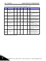
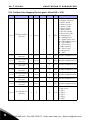
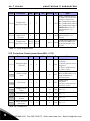
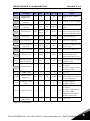
1
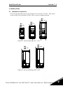
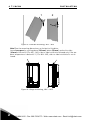
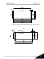
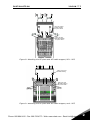
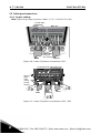
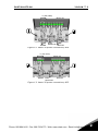
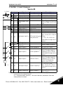
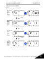
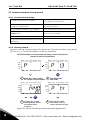
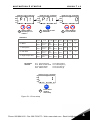
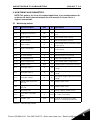
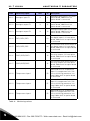
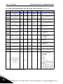
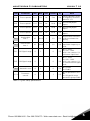
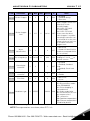
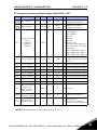
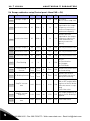
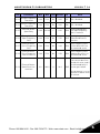
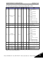
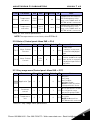
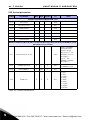
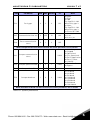
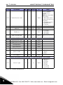
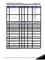
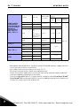
vacon®20 ac drives quick guide Phone: 800.894.0412 - Fax: 888.723.4773 - Web: www.clrwtr.com - Email: [email protected] Phone: 800.894.0412 - Fax: 888.723.4773 - Web: www.clrwtr.com - Email: [email protected] safety Doc: DPD00511E1 Release: 08.03.2013 Sw Package: FW0107V008.vcx vacon •1 This quick guide includes the essential steps for easy installation and setup of your Vacon 20 frequency converter. Before commissioning your drive, download and read the complete Vacon 20 User Manual available at: Vacon website -> Downloads 1. SAFETY ONLY A COMPETENT ELECTRICIAN IS ALLOWED TO CARRY OUT THE ELECTRICAL INSTALLATION! This quick guide contains clearly marked warnings which are intended for your personal safety and to avoid any unintentional damage to the product or connected appliances. Please read these warnings carefully: The components of the power unit of the frequency converter are live when Vacon 20 is connected to mains. Coming into contact with this voltage is extremely dangerous and may cause death or severe injury. The motor terminals U, V, W (T1, T2, T3) and the possible brake resistor terminals - / + are live when Vacon 20 is connected to mains, even if the motor is not running. The control I / O-terminals are isolated from the mains potential. However, the relay output terminals may have a dangerous control voltage present even when Vacon 20 is disconnected from mains. ! The earth leakage current of Vacon 20 frequency converters exceeds 3.5 mA AC. According to standard EN61800-5-1, a reinforced protective ground connection must be ensured. See Chapter 7! If the frequency converter is used as a part of a machine, the machine manufacturer is responsible for providing the machine with a main switch (EN 60204-1). If Vacon 20 is disconnected from mains while running the motor, it remains live if the motor is energized by the process. In this case the motor functions as a generator feeding energy to the frequency converter. After disconnecting the frequency converter from the mains, wait until the fan stops and the display segments or status leds on the front panel go out. Wait 5 more minutes before doing any work on Vacon 20 connections. The motor can start automatically after a fault situation, if the autoreset function has been activated. Phone: 800.894.0412 - Fax: 888.723.4773 - Web: www.clrwtr.com - Email: [email protected] 1 2 1 • vacon safety Phone: 800.894.0412 - Fax: 888.723.4773 - Web: www.clrwtr.com - Email: [email protected] installation vacon •3 2. INSTALLATION 2.1 Mechanical installation There are two possible ways to mount Vacon 20 in the wall. For MI1 - MI3, either screw or DIN-rail mounting; For MI4 - MI5, screw or flange mounting. MI3 =M5 MI2 MI1 =M5 =M4 BACK RESET LOC REM BACK RESET LOC REM LOC REM BACK RESET OK OK OK Figure 1: Screw mounting, MI1 - MI3 MI5 MI4 =M 6 =M 6 BA CK RES TE LOC REM OK LOC RE M BA CK RES TE OK Figure 2: Screw mounting, MI4 - MI5 Phone: 800.894.0412 - Fax: 888.723.4773 - Web: www.clrwtr.com - Email: [email protected] 2 4 • vacon installation 1 2 Figure 3: DIN-rail mounting, MI1 - MI3 Note! See the mounting dimensions on the back of the drive. Leave free space for cooling above (100 mm), below (50 mm), and on the sides (20 mm) of Vacon 20! (For MI1 - MI3, side-to-side installation allowed only if the ambient temperature is below 40 °C; For MI4 - MI5, side-to-side installation is not allowed. BACK RESET LOC REM OK Figure 4: flange mounting, MI4 – MI5 2Phone: 800.894.0412 - Fax: 888.723.4773 - Web: www.clrwtr.com - Email: [email protected] installation vacon •5 Drive outline Opening outline Figure 5: Flange mounting cutout dimensions for MI4 (Unit: mm) Drive outline Opening outline Figure 6: Flange mounting cutout dimensions for MI5 (Unit: mm) Phone: 800.894.0412 - Fax: 888.723.4773 - Web: www.clrwtr.com - Email: [email protected] 2 6 • vacon installation M14 M15 Figure 7: Flange mounting depth dimensions for MI4 and MI5 (Unit: mm) 2Phone: 800.894.0412 - Fax: 888.723.4773 - Web: www.clrwtr.com - Email: [email protected] installation vacon •7 . Attach the support AFTER installing the power cables Attach this plate BEFORE installing the power cables Figure 8: Attaching the PE-plate and API cable support, MI1 - MI3 Attach the support AFTER installing Attach this plate BEFORE installing the power cables Figure 9: Attaching the PE-plate and API cable support, MI4 - MI5 Phone: 800.894.0412 - Fax: 888.723.4773 - Web: www.clrwtr.com - Email: [email protected] 2 8 • vacon installation 2.2 Cabling and connections 2.2.1 Power cabling Note! Tightening torque for power cables is 0.5 - 0.6 Nm (4-5 in.lbs). 3~ (230V, 400V) Motor out 1~ (230V) Strip the plastic cable coating for 360° earthing MOTOR MAINS Figure 10: Vacon 20 power connections, MI1 3~(230V, 400V, 575V) External brake resistor 3~(230V, 400V, 575V) 1~ (230V) 1~ (115V) Mot or out L1 L2/N L3 R+ R- U/ T1 V/T2 W/T3 Strip the plastic cable coating for 360° earthing MAINS BRAKE RESISTOR MOTOR Figure 11: Vacon 20 power connections, MI2 - MI3 2Phone: 800.894.0412 - Fax: 888.723.4773 - Web: www.clrwtr.com - Email: [email protected] installation vacon •9 3~ (380, 480V) Motor out Brake RESISTOR MOTOR MAINS Figure 12: Vacon 20 power connections, MI4 3~ (380, 480V) Motor out MAINS Brake RESISTOR MOTOR Figure 13: Vacon 20 power connections, MI5 Phone: 800.894.0412 - Fax: 888.723.4773 - Web: www.clrwtr.com - Email: [email protected] 2 10 • vacon installation 2.2.2 Control cabling Figure 14: Open the lid MI1 - MI3 Figure 15: Open the lid MI4 - MI5 2Phone: 800.894.0412 - Fax: 888.723.4773 - Web: www.clrwtr.com - Email: [email protected] installation vacon • 11 Control cable tightening torque: 0.4 Nm Strip the plastic cable coating for 360°earthing Figure 16: Install the control cables, MI1 - MI3 Figure 17: Install the control cables, MI4 - MI5 Phone: 800.894.0412 - Fax: 888.723.4773 - Web: www.clrwtr.com - Email: [email protected] 2 12 • vacon installation 2.2.3 Allowed option boards in Vacon20 See below for the allowed option boards in the slot: 6/27 ( ( ( ( % % % % % %+ %) Note! OPT-B1 and OPT-B4 only support external power supply. Option board assembly structure: 1 2 3 2Phone: 800.894.0412 - Fax: 888.723.4773 - Web: www.clrwtr.com - Email: [email protected] installation vacon • 13 4 5 6 Phone: 800.894.0412 - Fax: 888.723.4773 - Web: www.clrwtr.com - Email: [email protected] 2 14 • vacon installation 2Phone: 800.894.0412 - Fax: 888.723.4773 - Web: www.clrwtr.com - Email: [email protected] vacon 20 api vacon • 15 3. CONTROL I / O AND TERMINALS Vacon 20 1-10 k Terminal 1 +10 Vref 2 AI1 3 GND 6 24 Vout Signal Factory preset Ref voltage out Analogue signal in 1 Freq reference P) I / O signal ground 24 V output for DI's 7 DI_C Digital Input Common 8 9 10 A B DI1 DI2 DI3 A B Digital input 1 Digital input 2 Digital input 3 RS485 signal A RS485 signal B 4 AI2 5 GND 13 DO14 DI4 15 DI5 16 DI6 mA 18 AO 20 DO Description Maximum load 10 mA 0 - 10 V, Ri >= 200 k 20 %, max load 50 mA Digital Input for DI1- DI6, refer to Table 2 for DI sink type 18 - 30 V, Ri > 5 k Start forward P) Start reverse P) Fault reset P) FB Communication Negative FB Communication Positive Default: 0(4) - 20 mA, Ri <= 250 Analogue signal in PID actual value and Other: 2 Freq reference P) 0 - 10 V, Ri >= 200 k Selectable through microswitch I / O signal ground Digital Output Digital Output Common Common Digital input 4 Preset speed B0 P) 18 - 30 V, Ri > 5 k As DI, Other: Encoder Input A P) Digital input 5 (frequency up to 10 kHz) Preset speed B1 Selectable through microswitch As DI, Other: Encoder Input B P) Digital input 6 (frequency up to 10 kHz), External Fault Pulse Train Input (frequency up to 5 kHz) 0 - 10 V, RL >1 K 0(4) - 20 mA, RL < 500 Analogue Output Output frequency P) Selectable through microswitch Open collector, max load Digital signal out Active = READY P) 48 V / 50 mA Table 1: Vacon 20 General purpose application default I / O configuration and connections for control board P) = Programmable function, See User Manual: parameter lists and descriptions for detail Phone: 800.894.0412 - Fax: 888.723.4773 - Web: www.clrwtr.com - Email: [email protected] 3 16 • vacon vacon 20 api Terminal 22 RO 13 Signal Factory preset Relay out 1 Active = RUN P) 23 RO 14 24 RO 22 25 RO 21 26 RO 24 Description Max switching load: 250 Vac / 2 A or 250 Vdc / 0.4 A Max switching load: 250 Vac / 2 A or 250 Vdc / 0.4 A Relay out 2 Active = FAULT P) Table 1: Vacon 20 General purpose application default I / O configuration and connections for control board P) = Programmable function, See User Manual: parameter lists and descriptions for detail Terminal Signal 3 GND I / O signal ground 6 24 Vout 24 V output for DI's Digital Input Com7 DI_C mon 8 DI1 Digital input 1 9 DI2 Digital input 2 10 DI3 Digital input 3 14 DI4 Digital input 4 15 DI5 Digital input 5 16 DI6 Digital input 6 Factory preset Description 20 %, max load 50 mA Digital Input Common for DI1-DI6 18 - 30 V, Ri > 5 k Start forward P) Start reverse P) Fault reset P) Preset speed B0 P) 18 - 30 V, Ri > 5 k Preset speed B1 P) Only for DI. Only for DI. External Fault P) Table 2: DI Sink Type, remove jumper J500 and connect the wire using table 2 J500 S4 S3 S2 S1 AI2 mA V RS485 - term DI Enco Nor AO V mA ON OFF Figure 18: Microswitchs Vacon 20 I / O terminals: AI2 GND DO- DI4 DI5 DI6 AO DO+ 4 5 1 13 2 14 3 15 6 16 7 18 8 9 * R24 23 26 25 10 +10VAI1 GND 24V DI-C DI1 DI2 DI3 3 R13 R14 22 20 A B 24 R21 R22 Phone: 800.894.0412 - Fax: 888.723.4773 - Web: www.clrwtr.com - Email: [email protected] navigation & startup vacon • 17 4. NAVIGATION AND STARTUP 4. 1 The main menus of Vacon 20 REFERENCE MENU Dispalys the keypad reference value regardless of the selected contron place. RE ADY RU N RE ADY S TO P A L AR M FA U LT RE F R UN S T OP A L AR M FA U LT RE F M ON OK OK PA R MON PA R SYS PRES S SYS Hz F WD R EV I/O K E Y PA D Hz F WD BUS R EV I/O K EY PA D BUS PRES S MONITORING RE F MENU In this menu you can browse the monitoring values. R EAD Y RUN S T OP A L A R M FA U LT R EAD Y RUN ST O P A LA R M FA U L T RE F MO N OK M ON PA R PA R PRES S SYS SYS FWD R EV I/O K EY PA D FW D BU S R EV I/O K EY PA D B US PRES S PARAMETER R EF MENU In this menu you can browse and edit the parameters. R E AD Y RU N S TO P A L A R M F A U LT R E AD Y RU N S TO P A L A R M F A U LT R EF MO N OK PA R MO N PA R PRES S SYS SYS FWD RE V I/O K E YP A D FWD BUS REV I/O K E YP A D BUS PRES S RE A DY SYSTEM MENU RU N S TO P A L AR M F A U LT R EA D Y R EF Here you will be able to browse system parameter and fault submenu. RU N ST O P A L AR M FA U LT R EF MO N MO N OK PA R PA R PRES S SYS SYS FWD RE V I/O K E YP A D BU S FW D RE V I/ O K E YP A D B US Figure 19: The main menu of Vacon 20 Phone: 800.894.0412 - Fax: 888.723.4773 - Web: www.clrwtr.com - Email: [email protected] 4 18 • vacon navigation & startup 4.2 Commissioning and startup wizard 4.2.1 Commissioning steps: 1. Read safety instructions on page 1 7. Perform test run without motor, see the User Manual at Vacon website 2. Secure the grounding and check that cables comply with requirements 8. Run no-load tests without motor being connected to the process 3. Check quality and quantity of cooling air 9. Perform an identification run (Par. ID631) 4. Check that all start / stop switches are in STOP position 10. Connect the motor to the process and perform test run once again 5. Connect the drive to mains 11. Vacon 20 is now ready for use 6. Run the Startup wizard and set all necessary parameters Table 3: Commissioning steps 4.2.2 Startup wizard Vacon 20 runs the startup wizard in first power-up. The wizard can be run by setting SYS Par.4.2 =1. The following figures show the procedure. NOTE! Running the startup wizard will always return all parameter settings to their factory defaults! READY RUN S TO P ALARM FAU LT REF REF MON MON PAR PAR SYS READY RUN FWD REV S TO P ALARM FAU LT SYS FWD REV I/O KEY PAD BUS I/O KEY PAD BUS OK 1 Enter Par. menu, select P1.3 motor nominal speed READY RUN S TO P ALARM 2 Press OK enter edit mode READY FAU LT REF REF MON MON RUN S TO P ALARM FAU LT PAR PAR SYS rpm SYS FWD REV I/O KEY PAD BUS FWD REV I/O KEY PAD BUS OK 3 Change P1.3 value with Up/Down button and press OK to comfirm 4 Perform the same procedure for P1.4, motor nominal current Figure 20: Vacon 20 startup wizard (standard application) 4 Phone: 800.894.0412 - Fax: 888.723.4773 - Web: www.clrwtr.com - Email: [email protected] navigation & startup vacon • 19 READY RUN STOP ALARM FAULT REF READY RUN STOP ALARM FAULT REF READY RUN STOP ALARM FAULT REF MON MON MON PAR PAR PAR SYS SYS FWD REV SYS I/O KEYPAD BUS FWD REV I/O KEYPAD BUS FWD REV I/O KEYPAD BUS OK 1 Startup wizard showns par 17.1 numbe r. 2 Press OK to enter edit mode. Select between 0-3, see below! 3 Selections: 0 = Basic P1.7 P1.8 P1.15 P2.2 P2.3 P3.1 P4.2 P4.3 1.5 x 0= Frequecny control 0= Not used 0= Ramp 0= Coast 0 Hz 3s 3s 0= Frequecny control 0= Not used 0= Ramp 1= Ramp 20 Hz 5s 5s 0= Frequecny control 0= Not used 1= Flying 0= Coast 20 Hz 20s 20s 1=Open loop speed ontrol 1= used 0= Ramp 0= Coast 0 Hz 1s 1s INMOT 1.1 x 1 = Pump drive INMOT 1.1 x 2 = Fan drive 3 = High Torque drive Parameters affected: INMOT 1.5 x INMOT P1.7 Current limit (A) P1.8 Motor control mode P1.15 Torque boost P2.2 Start function P2.3 P3.1 P4.2 P4.3 Stop function Min frequency Acc. time (s) Dec time (s) READY RUN STOP ALARM FAULT REF MON PAR SYS FWD REV I/O KEYPAD BUS OK 4 Press OK to confirm drive setup Figure 21: Drive setup Phone: 800.894.0412 - Fax: 888.723.4773 - Web: www.clrwtr.com - Email: [email protected] 4 20 • vacon 4 navigation & startup Phone: 800.894.0412 - Fax: 888.723.4773 - Web: www.clrwtr.com - Email: [email protected] monitoring & parameters vacon • 21 5. MONITORING AND PARAMETERS NOTE! This guide is for Vacon 20 standard application, if you need parameter descriptions for detail, please download the user manual on Vacon website -> Support & downloads. 5.1 Monitoring values Code Monitoring signal Unit ID V1.1 Output frequency Hz 1 Description Output frequency to motor V1.2 Frequency reference Hz 25 Frequency reference to motor control Calculated motor speed V1.3 Motor speed rpm 2 V1.4 Motor current A 3 Measured motor current V1.5 Motor torque % 4 Calculated actual / nominal torque of the motor V1.6 Motor shaft power % 5 Calculated actual / nominal power of the motor V1.7 Motor voltage V 6 Motor voltage V1.8 DC-link voltage V 7 Measured DC-link voltage V1.9 Unit temperature °C 8 Heatsink temperature V1.10 Motor temperature V1.11 Output Power V2.1 % 9 Calculated motor temperature KW 79 Output power from drive to motor Analogue input 1 % 59 AI1 signal range in percent of used range V2.2 Analogue input 2 % 60 AI2 signal range in percent of used range V2.3 Analogue output % 81 AO signal range in percent of used range V2.4 Digital input status DI1, DI2, DI3 15 Digital input status V2.5 Digital input status DI4, DI5, DI6 16 Digital input status V2.6 RO1, RO2, DO V2.7 Pulse train / encoder input V2.8 Encoder rpm 17 Relay / digital output status % 1234 0 - 100% scale value rpm 1235 Scaled according to Encoder pulses / revolution parameter Table 4: Monitoring values Phone: 800.894.0412 - Fax: 888.723.4773 - Web: www.clrwtr.com - Email: [email protected] 5 22 • vacon Code Monitoring signal monitoring & parameters Unit ID Description V2.11 Analogue input E1 % 61 Analogue input signal 1 in % from option board, hidden until an option board is connected V2.12 Analogue output E1 % 31 Analogue output signal 1 in % from option board, hidden until an option board is connected V2.13 Analogue output E2 % 32 Analogue output signal 2 in % from option board, hidden until an option board is connected V2.14 DIE1, DIE2, DIE3 33 This monitor value shows status of the digital inputs 1-3 from option board, hidden until an option board is connected V2.15 DIE4, DIE5, DIE6 34 This monitor value shows status of the digital inputs 4-6 from option board, hidden until an option board is connected V2.16 DOE1,DOE2,DOE3 35 This monitor value shows status of the relay outputs 1-3 from option board, hidden until an option board is connected V2.17 DOE4,DOE5,DOE6 36 This monitor value shows status of the relay outputs 4-6 from option board, hidden until an option board is connected V2.18 Temperature input 1 50 Measured value of Temperature input 1 in temperature unit ( Celsius or Kelvin) by parameter setting, hidden until an option board is connected V2.19 Temperature input 2 51 Measured value of Temperature input 2 in temperature unit ( Celsius or Kelvin) by parameter setting, hidden until an option board is connected V2.20 Temperature input 3 52 Measured value of Temperature input 3 in temperature unit ( Celsius or Kelvin) by parameter setting, hidden until an option board is connected Table 4: Monitoring values 5 Phone: 800.894.0412 - Fax: 888.723.4773 - Web: www.clrwtr.com - Email: [email protected] monitoring & parameters Code V3.1 V3.2 Monitoring signal Unit Drive status word Application status word vacon • 23 ID Description 43 Bit codes status of drive B0 = Ready B1 = Run B2 = Reverse B3 = Fault B6 = RunEnable B7 = AlarmActive B12 = RunRequest B13 = MotorRegulatorActive 89 Bit codes status of application: B3 = Ramp 2 Active B5 = Remote CTRL Place 1 active B6 = Remote CTRL Place 2 active B7 = Fieldbus Control Active B8 = Local Control Active B9 = PC Control Active B10 = Preset Frequencies Active 56 B0 = DI1 B1 = DI2 B2 = DI3 B3 = DI4 B4 = DI5 B5 = DI6 B6 = DIE1 B7 = DIE2 B8 = DIE3 B9 = DIE4 B10 = DIE5 B11 = DIE6 Regulator setpoint V3.3 DIN status word V4.1 PID set point % 20 V4.2 PID feedback value % 21 Regulator actual value V4.3 PID error % 22 Regulator error V4.4 PID output % 23 Regulator output V4.5 Process 29 Scaled process variable see par. 15.18 Table 4: Monitoring values Phone: 800.894.0412 - Fax: 888.723.4773 - Web: www.clrwtr.com - Email: [email protected] 5 24 • vacon monitoring & parameters 5.2 Quick setup parameters (Virtual menu, shows when par. 17.2 = 1) Code Parameter P1.1 Motor nominal voltage Min P1.2 Motor nominal frequency P1.3 Motor nominal speed 30 P1.4 Motor nominal current P1.5 Motor cos P1.7 Max Unit Default ID Note V Varies 110 Check rating plate on the motor. Hz 50.00 / 60.00 111 Check rating plate on the motor. 20000 rpm 1440 / 1720 112 Default applies for a 4pole motor. 0.2 x INunit 2.0 x INunit A INunit 113 Check rating plate on the motor. 0.30 1.00 0.85 120 Check rating plate on the motor. Current limit 0.2 x INunit 2.0 x INunit 1.5 x INunit 107 Maximum motor current 180 690 30.00 320.00 A P1.15 Torque boost 0 1 0 109 0 = Not used 1 = Used P2.1 Remote control place 1 selection 0 2 0 172 0 = I / O terminal 1 = Fieldbus 2 = Keypad P2.2 Start function 0 1 0 505 0 = Ramp 1 = Flying start P2.3 Stop function 0 1 0 506 0 = Coasting 1 = Ramp P3.1 Min frequency 0.00 P3.2 Hz 0.00 101 Minimum freq reference Hz 50.00 / 60.00 102 Maximum freq reference 117 1 = Preset speed 0 2 = Keypad 3 = Fieldbus 4 = AI1 5 = AI2 6 = PID 7 = AI1 + AI2 8 = Motor potentiometer 9 = Pulse train / Encoder 10 = AIE1 11 = Temperature input 1 12 = Temperature input 2 13 = Temperature input 3 P3.2 P3.3 Max frequency Remote Control Place 1 frequency reference selection P3.1 320.00 1 Varies 7 Table 5: Quick setup parameters 5 Phone: 800.894.0412 - Fax: 888.723.4773 - Web: www.clrwtr.com - Email: [email protected] monitoring & parameters Code Parameter Min Max Unit vacon Default ID • 25 Note P3.4 Preset speed 0 P3.1 P3.2 Hz 5.00 180 Preset speed 0 is used as frequency reference when P3.3 = 1 P3.5 Preset speed 1 P3.1 P3.2 Hz 10.00 105 Activated by digital inputs P3.6 Preset speed 2 P3.1 P3.2 Hz 15.00 106 Activated by digital inputs P3.7 Preset speed 3 P3.1 P3.2 Hz 20.00 126 Activated by digital inputs P4.2 Acceleration time 1 0.1 3000.0 s 3.0 103 Acceleration time from 0 Hz to maximum frequency. P4.3 Deceleration time 1 0.1 3000.0 s 3.0 104 Deceleration time from maximum frequency to 0 Hz. P6.1 AI1 Signal range 0 1 0 379 0 = 0 - 100% 1 = 20% - 100% 20% is the same as 2 V minimum signal level. P6.5 AI2 Signal range 0 1 0 390 0 = 0 - 100% 1 = 20% - 100% 20% is the same as 2 V or 4 mA minimum signal level. P14.1 Automatic reset 0 1 0 731 0 = Disable 1 = Enable P17.2 Parameter conceal 0 1 1 115 0 = All parameters visible 1 = Only quick setup parameter group visible Table 5: Quick setup parameters Phone: 800.894.0412 - Fax: 888.723.4773 - Web: www.clrwtr.com - Email: [email protected] 5 26 • vacon monitoring & parameters 5.3 Motor settings (Control panel: Menu PAR -> P1) Code Parameter P1.1 Motor nominal voltage P1.2 Motor nominal frequency P1.3 Motor nominal speed P1.4 Motor nominal current P1.5 Motor cos Min 180 Max 690 30.00 320.00 30 20000 0.2 x 2.0 x INunit INunit Unit Default ID Note V Varies 110 Check rating plate on the motor Hz 50.00 / 60.00 111 Check rating plate on the motor rpm 1440 / 1720 112 Default applies for a 4-pole motor. A INunit 113 Check rating plate on the motor 0.30 1.00 0.85 120 Check rating plate on the motor 0 1 0 650 0 = Induction 1 = Permanent magnet (Power Factor) P1.6 Motor type P1.7 Current limit P1.8 Motor control mode 0 1 0 600 P1.9 U / f ratio 0 2 0 0 = Linear 108 1 = Square 2 = Programmable P1.10 Field weakening point 8.00 320.00 Hz 50.00 / 60.00 602 Field weakening point frequency P1.11 Field weakening 10.00 200.00 point voltage % 100.00 603 Voltage at field weakening point as % of Unmot Mid point frequency for programmable U / f 0.2 x 2.0 x INunit INunit A 1.5 x INunit 107 Maximum motor current 0 = Frequency control 1 = Open loop speed control P1.12 U / f mid point frequency 0.00 P1.10 Hz 50.00 / 60.00 604 P1.13 U / f mid point voltage 0.00 P1.11 % 100.00 Mid point voltage for pro605 grammable U / f as % of Unmot P1.14 Zero freq voltage 0.00 40.00 % Varies 606 Voltage at 0 Hz as % of Unmot 0 109 0 = Disabled 1 = Enabled P1.15 Torque Boost 0 1 P1.16 Switching frequency 1.5 16.0 kHz 4.0 / 2.0 PWM frequency. If values 601 are higher than default, reduce the current capacity Table 6: Motor settings 5 Phone: 800.894.0412 - Fax: 888.723.4773 - Web: www.clrwtr.com - Email: [email protected] monitoring & parameters Code P1.17 Parameter Brake Chopper Min 0 Max vacon Unit Default 2 0 ID Note 0 = Disabled 504 1 = Enabled: Always 2 = Run state Brake chopper control activation level in volt. For 240V Supply: 240*1.35*1.18 = 382V For 400V Supply: 400*1.35*1.18 = 638V 1267 Please note that when brake chopper is used the overvoltage controller can be switched off or the overvoltage reference level can be set above the brake chopper level. P1.18 Brake chopper level 0 911 P1.19 Motor identification 0 1 P1.20 Rs voltage drop P1.21 Overvoltage controller 0 2 1 0 = Disabled 1 = Enabled, Standard 607 mode 2 = Enabled, Shock load mode P1.22 Undervoltage controller 0 1 1 608 0 = Disable 1 = Enable P1.23 Sine filter 0 1 0 522 0 = Not in use 1 = In use P1.24 Modulator type 0.00 100.00 0 65535 V varies 0 % 0.00 28928 • 27 631 0 = Not active 1 = Standstill identification (need run command within 20 s to activate) Voltage drop over motor 662 windings as % of Unmot at nominal current. Modulator configuration word: B1 = Discontinuous modulation (DPWMMIN) B2 = Pulse dropping in overmodulation B6 = Under modulation 648 B8 = Instantaneous DC voltage compensation * B11 = Low noise B12 = Dead time compensation * B13 = Flux error compensation * * Enabled by default Table 6: Motor settings NOTE! These parameters are shown, when P17.2 = 0. Phone: 800.894.0412 - Fax: 888.723.4773 - Web: www.clrwtr.com - Email: [email protected] 5 28 • vacon monitoring & parameters 5.4 Start / stop setup (Control panel: Menu PAR -> P2) Code Parameter Min Max Unit Default ID Note P2.1 Remote Control Place Selection 0 2 0 0 = I / O terminals 172 1 = Fieldbus 2 = Keypad P2.2 Start function 0 1 0 505 0 = Ramp 1 = Flying start P2.3 Stop function 0 1 0 506 0 = Coasting 1 = Ramp P2.4 I / O Start / Stop logic 0 4 2 I / O control I / O control signal 1 signal 2 0 Forward Reverse 300 1 Fwd(edge) Inverted Stop 2 Fwd(edge) Bwd(edge) 3 Start Reverse 4 Start(edge) Reverse P2.5 Local / Remote 0 1 0 211 0 = Remote control 1 = Local control P2.6 Keypad control direction 0 1 0 123 0 = Forward 1 = Reverse P2.7 Keypad stop button 0 1 1 114 0 = Keypad control only 1 = Always P2.8 Remote Control Place 2 Selection 0 2 0 0 = I / O terminals 173 1 = Fieldbus 2 = Keypad P2.9 keypad button lock 0 1 0 15520 0 = unlock all keypad button 1 = Loc/Rem button locked Table 7: Start / stop setup 5 Phone: 800.894.0412 - Fax: 888.723.4773 - Web: www.clrwtr.com - Email: [email protected] monitoring & parameters vacon • 29 5.5 Frequency references (Control panel: Menu PAR -> P3) Code P3.1 P3.2 Parameter Min frequency Max frequency Min Max 0.00 P3.1 P3.2 320.00 Unit Default Hz 0.00 Hz 50.00 / 60.00 ID Note Minimum allowed 101 frequency reference 102 Maximum allowed frequency reference 7 1 = Preset speed 0 2 = Keypad 3 = Fieldbus 4 = AI1 5 = AI2 6 = PID 117 7 = AI1 + AI2 8 = Motor potentiometer 9 = Pulse train / Encoder 10 = AIE1 11 = Temperature input 1 12 = Temperature input 2 13 = Temperature input 3 Hz 5.00 Preset speed 0 is used as 180 frequency reference when P3.3 = 1 P3.2 Hz 10.00 105 Activated by digital inputs P3.2 Hz 15.00 106 Activated by digital inputs P3.1 P3.2 Hz 20.00 126 Activated by digital inputs Preset speed 4 P3.1 P3.2 Hz 25.00 127 Activated by digital inputs P3.9 Preset speed 5 P3.1 P3.2 Hz 30.00 128 Activated by digital inputs P3.10 Preset speed 6 P3.1 P3.2 Hz 40.00 129 Activated by digital inputs P3.11 Preset speed 7 P3.1 P3.2 Hz 50.00 130 Activated by digital inputs Remote Control Place 2 freP3.12 quency reference selection 1 Varies P3.13 Motor Potentionmeter Ramp 1 50 P3.14 Motor Potentionmeter Reset 0 2 P3.3 Remote Control Place 1 frequency reference selection 1 Varies P3.4 Preset speed 0 P3.1 P3.2 P3.5 Preset speed 1 P3.1 P3.6 Preset speed 2 P3.1 P3.7 Preset speed 3 P3.8 Hz/s 5 131 See P3.3 5 331 Speed variation rate 2 0 = No Reset 367 1 = Reset if stopped 2 = Reset if powered down Table 8: Frequency references NOTE! These parameters are shown, when P17.2 = 0. Phone: 800.894.0412 - Fax: 888.723.4773 - Web: www.clrwtr.com - Email: [email protected] 5 30 • vacon monitoring & parameters 5.6 Ramps and brakes setup (Control panel: Menu PAR -> P4) Code P4.1 Parameter Ramp S-shape 1 P4.2 Acceleration time 1 P4.3 Deceleration time 1 0.0 0.1 0.1 Max 10.0 3000.0 3000.0 Unit Default s s s ID Note 0.0 0 = Linear 500 >0 = S-curve ramp time 3.0 Defines the time required for the output 103 frequency to increase from zero frequency to maximum frequency. 3.0 Defines the time required for the output frequency to decrease 104 from maximum frequency to zero frequency. 0.0 10.0 s 0.0 501 See the parameter P4.1 P4.5 Acceleration time 2 0.1 3000.0 s 10.0 502 See the parameter P4.2 P4.6 Deceleration time 2 0.1 3000.0 s 10.0 503 See the parameter P4.3 P4.4 Ramp S-shape 2 Min P4.7 Flux Braking 0 3 P4.8 Flux Braking Current 0.5 x INunit 2.0 x INunit P4.9 DC Braking Current 0.3 x INunit 2.0 x INunit 0 520 0 = Off 1 = Deceleration 2 = Chopper 3 = Full Mode A INunit 519 Defines the current level for flux braking. A INunit Defines the current 507 injected into the motor during DC brakeing. P4.10 Stop DC current time 0.00 600.00 s 0.00 Determines if braking is ON or OFF and the braking time of the DC-brake 508 when the motor is stopping. 0.00 = Not active P4.11 Stop DC current frequency 0.10 10.00 Hz 1.50 The output frequency at 515 which the DC-braking is applied. P4.12 Start DC current time 0.00 600.00 s 0.00 516 0.00 = Not active Table 9: Ramps and brakes setup 5 Phone: 800.894.0412 - Fax: 888.723.4773 - Web: www.clrwtr.com - Email: [email protected] monitoring & parameters vacon Code Parameter Min Max P4.13 Accel2 Frequency Threshold 0.00 P3.2 Hz 0.00 527 0.00 = disabled P4.14 Decel2 Frequency Threshold 0.00 P3.2 Hz 0.00 528 0.00 = disabled P4.15 External Brake: Open Delay 0.00 320.00 s 0.20 Delay to open brake 1544 after Open frequency limit is reached. P4.16 External Brake: Open Frequency limit 0.00 P3.2 Hz 1.50 Opening frequency from 1535 forward and reverse direction. P4.17 External Brake : Close Frequency limit 0.00 P3.2 Hz 1.00 Close frequency from 1539 positive direction if no run command active. P4.18 External Brake : Close Frequency limit in Reverse 0.00 P3.2 Hz 1.50 Close frequency from 1540 negative direction if no run command active. P4.19 External Brake : Open/Close Current limit 0.0 200.0 Unit Default % 20.0 ID • 31 Note The brake is not opened if the current does not exceed this value, and is closed immediately if 1585 current goes below. This parameter is set as a percent of Motor nominal current. Table 9: Ramps and brakes setup Phone: 800.894.0412 - Fax: 888.723.4773 - Web: www.clrwtr.com - Email: [email protected] 5 32 • vacon monitoring & parameters 5.7 Digital inputs (Control panel: Menu PAR -> P5) Code Parameter Min Max Unit Default ID Note P5.1 I / O control signal 1 0 Varies 1 0 = Not used 1 = DI1 2 = DI2 3 = DI3 4 = DI4 5 = DI5 403 6 = DI6 7 = DIE1 8 = DIE2 9 = DIE3 10 = DIE4 11 = DIE5 12 = DIE6 P5.2 I / O control signal 2 0 Varies 2 404 See 5.1 P5.3 Reverse 0 Varies 0 412 See 5.1 P5.4 Ext. fault Close 0 Varies 6 405 See 5.1 P5.5 Ext. fault Open 0 Varies 0 406 See 5.1 P5.6 Fault reset 0 Varies 3 414 See 5.1 P5.7 Run enable 0 Varies 0 407 See 5.1 P5.8 Preset speed B0 0 Varies 4 419 See 5.1 P5.9 Preset speed B1 0 Varies 5 420 See 5.1 P5.10 Preset speed B2 0 Varies 0 421 See 5.1 P5.11 Ramp time 2 selection 0 Varies 0 408 See 5.1 Motor potentiomeP5.12 ter up 0 Varies 0 418 See 5.1 Motor potentiomeP5.13 ter down 0 Varies 0 417 See 5.1 P5.14 Remote control place 2 0 Varies 0 425 Activates control place 2 See 5.1 P5.15 Remote control plece freq reference 2 0 Varies 0 343 Activates control place 2 See parameter 5.1 Table 10: Digital inputs 5 Phone: 800.894.0412 - Fax: 888.723.4773 - Web: www.clrwtr.com - Email: [email protected] monitoring & parameters Code Parameter Min Max P5.16 PID setpoint 2 0 Varies P5.17 Motor Preheat Active 0 vacon Unit Default Varies ID • 33 Note Activates reference 2 See 5.1 0 1047 0 Activates the Motor Preheat (DC-Current) in stop state when parame1044 ter Motor Preheat function is set to 2 See 5.1 Table 10: Digital inputs 5.8 Analogue inputs (Control panel: Menu PAR -> P6) Code Parameter Min 0 Max Unit 1 Default P6.1 AI1 Signal range P6.2 AI1 Custom min -100.00 100.00 % 0.00 P6.3 AI1 Custom max -100.00 300.00 % 100.00 s 0.1 P6.4 AI1 filter time 0.0 10.0 P6.5 AI2 signal range 0 1 0 0 ID 380 0.00 = no min scaling 381 100.00 = no max scaling 378 0 = no filtering 390 See P6.1 P6.6 AI2 Custom min -100.00 100.00 % 0.00 391 See P6.2 P6.7 AI2 Custom max -100.00 300.00 % 100.00 392 See P6.3 s 0.1 389 See P6.4 P6.8 AI2 filter time P6.9 AIE1 Signal range 0.0 10.0 0 1 Note 0 = 0 - 100% ( 0 - 10 V) 379 1 = 20% - 100% ( 2 - 10 V) 0 See P6.1, hidden until an 143 option board is connected P6.10 AIE1 Custom Min -100.00 100.00 % 0.00 See P6.2, hidden until an 144 option board is connected P6.11 AIE1 Custom Max -100.00 300.00 % 100.00 See P6.3, hidden until an 145 option board is connected P6.12 s 0.1 See P6.4, hidden until an 142 option board is connected AIE1 Filter time 0.0 10.0 Table 11: Analogue inputs Phone: 800.894.0412 - Fax: 888.723.4773 - Web: www.clrwtr.com - Email: [email protected] 5 34 • vacon monitoring & parameters 5.9 Pulse train / Encoder (Control panel: Menu PAR -> P7) Code Parameter Min Max Unit Default ID Note Pulse frequency to be 1229 interpreted as a 0% signal. P7.1 Min pulse frequency 0 10000 Hz 0 P7.2 Max pulse frequency 0.0 10000 Hz 10000 P7.3 Freq ref at min pulse freq 0.00 P3.2 Hz 0.00 Frequency correspond1231 ing to 0% if used as frequency reference. P7.4 Freq ref at max pulse freq 0.00 P3.2 Hz 50.00 / 60.00 Frequency correspond1232 ing to 100% if used as frequency reference. P7.5 Encoder direction 0 2 P7.6 Encoder pulses / revolution 1 65535 P7.7 Config DI5 and DI6 0 2 0 ppr 256 0 Pulse frequency to be 1230 interpreted as a 100% signal. 0 = Disable 1233 1 = Enable / Normal 2 = Enable / Inverted 629 Pulse count of encoder per round. Used for scaling encoder rpm monitor value only. 0 = DI5 and DI6 are for normal digital input 1165 1 = DI6 is for pulse train 2 = DI5 and DI6 are for encoder frequence mode Table 12: Pulse train/Encoder 5 Phone: 800.894.0412 - Fax: 888.723.4773 - Web: www.clrwtr.com - Email: [email protected] monitoring & parameters vacon • 35 5.10 Digital outputs (Control panel: Menu PAR -> P8) Code Parameter Min Max Unit Default ID Selections P8.1 RO1 signal selection 0 Varies 2 0 = Not used 1 = Ready 2 = Run 3 = Fault 4 = Fault Inverted 5 = Warning 6 = Reversed 7 = At Speed 8 = Motor regulator active 9 = FB Control Word.B13 313 10 = FB Control Word.B14 11 = FB Control Word.B15 12 = Output freq superv. 13 = Output torque superv. 14 = Unit temperature superv. 15 = Analogue input superv. 16 = Preset Speed Active 17 = External Brake ctrl 18 = Keypad control active 19 = I / O control active 20 = Temperature supervision P8.2 RO2 signal selcetion 0 Varies 3 314 See 8.1 P8.3 DO1 signal selcetion 0 Varies 1 312 See 8.1 P8.4 RO2 inversion 0 1 0 1588 P8.5 RO2 ON delay 0.00 320.00 s 0.00 P8.6 RO2 OFF delay 0.00 320.00 s 0.00 P8.7 RO1 inversion 0 1 P8.8 RO1 ON delay 0.00 320.00 s 0.00 458 0.00 = No delay P8.9 RO1 OFF delay 0.00 320.00 s 0.00 459 0.00 = No delay P8.10 DOE1 signal selection 0 Varies 0 317 See 8.1, hidden until an option board is connected P8.11 DOE2 signal selection 0 Varies 0 318 See 8.1, hidden until an option board is connected P8.12 DOE3 signal selection 0 Varies 0 1386 See 8.1, hidden until an option board is connected 0 0 = No inversion 1 = Inverted 460 0.00 = No delay 461 0.00 = No delay 1587 0 = No inversion 1 = Inverted Table 13: Digital outputs Phone: 800.894.0412 - Fax: 888.723.4773 - Web: www.clrwtr.com - Email: [email protected] 5 36 • vacon monitoring & parameters Code Parameter Min Max P8.13 DOE4 signal selection 0 Varies Unit Default 0 1390 ID See 8.1, hidden until an option board is connected Selections P8.14 DOE5 signal selection 0 Varies 0 1391 See 8.1, hidden until an option board is connected P8.15 DOE6 signal selection 0 Varies 0 139 See 8.1, hidden until an option board is connected Table 13: Digital outputs 5.11 Analogue outputs (Control panel: Menu PAR -> P9) Code Parameter Min Max Unit Default ID Selections P9.1 Analogue output signal selection 0 14 1 0 = Not used 1 = Output freq (0-fmax) 2 = Output current (0-InMotor) 3 = Motor torque (0-TnMotor) 4 = PID output (0 - 100%) 5 = Freq refer. (0-fmax) 6 = Motor speed (0-nmax) 7 = Motor power (0-PnMotor) 8 = Motor Voltage (0-UnMotor) 307 9 = DC-link Voltage (0 - 1000 V) 10 = Process Data In1 (0 - 10000) 11 = Process Data In2 (0 - 10000) 12 = Process Data In3 (0 - 10000) 13 = Process Data In4 (0 - 10000) 14 = Test 100% P9.2 Analogue output minimum 0 1 0 310 P9.3 Analogue output scaling 0.0 1000.0 % 100.0 311 Scaling factor P9.4 Analogue output filter time 0.00 10.00 s 0.10 308 Filter time P9.5 Analogue output E1 signal selection 0 14 0 472 See P9.1, hidden until an option board is connected P9.6 Analogue output E1 minimum 0 1 0 475 See P9.2, hidden until an option board is connected 0 = 0 V / 0 mA 1 = 2 V / 4 mA Table 14: Analogue outputs 5 Phone: 800.894.0412 - Fax: 888.723.4773 - Web: www.clrwtr.com - Email: [email protected] monitoring & parameters vacon Unit Default ID • 37 Code Parameter Min Max P9.7 Analogue output E1 scaling 0.0 1000.0 % 100.0 476 See P9.3, hidden until an option board is connected Selections P9.8 Analogue output E1 filter time 0.00 10.00 s 0.10 473 See P9.4, hidden until an option board is connected P9.9 Analogue output E2 signal selection 0 14 0 479 See P9.1, hidden until an option board is connected P9.10 Analogue output E2 minimum 0 1 0 482 See P9.2, hidden until an option board is connected P9.11 Analogue output E2 scaling 0.0 1000.0 % 100.0 483 See P9.3, hidden until an option board is connected P9.12 Analogue output E2 filter time 0.00 10.00 s 0.10 480 See P9.4, hidden until an option board is connected Table 14: Analogue outputs Phone: 800.894.0412 - Fax: 888.723.4773 - Web: www.clrwtr.com - Email: [email protected] 5 38 • vacon monitoring & parameters 5.12 Fieldbus Data-Mapping (Control panel: Menu PAR -> P10) Code Parameter Min Max Unit Default ID Note P10.1 FB Data Output 1 selection 0 Varies 0 0 = Frequency reference 1 = Output reference 2 = Motor speed 3 = Motor current 4 = Motor voltage 5 = Motor torque 6 = Motor power 7 = DC link voltage 8 = Active fault code 852 9 = Analogue AI1 10 = Analogue AI2 11 = Digital input state 12 = PID feedback value 13 = PID setpoint 14 = Pulse train / encoder input(%) 15 = Pulse train / encoder pulse() 16 = AIE1 P10.2 FB Data Output 2 selection 0 Varies 1 853 Variable mapped on PD2 FB Data Output 3 P10.3 selection 0 Varies 2 854 Variable mapped on PD3 FB Data Output 4 P10.4 selection 0 Varies 4 855 Variable mapped on PD4 FB Data Output 5 P10.5 selection 0 Varies 5 856 Variable mapped on PD5 FB Data Output 6 P10.6 selection 0 Varies 3 857 Variable mapped on PD6 FB Data Output 7 P10.7 selection 0 Varies 6 858 Variable mapped on PD7 FB Data Output 8 P10.8 selection 0 Varies 7 859 Variable mapped on PD8 0 PDI for Aux CW 0 = Not used 1 = PDI1 1167 2 = PDI2 3 = PDI3 4 = PDI4 5 = PDI5 P10.9 Aux CW Data In selection 0 5 Table 15: Fieldbus Data-Mapping 5 Phone: 800.894.0412 - Fax: 888.723.4773 - Web: www.clrwtr.com - Email: [email protected] monitoring & parameters vacon • 39 5.13 Prohibited Frequencies (Control panel: Menu PAR -> P11) Code Parameter P11.1 Prohibit Frequency Range 1 Low Limit Min Max Unit Default ID 0.00 P3.2 Hz 0.00 Low Limit 509 0.00 = Not used Note P11.2 Prohibit Frequency Range 1 High Limit 0.00 P3.2 Hz 0.00 510 High Limit 0.00 = Not used P11.3 Prohibit Frequency Range 2 Low Limit 0.00 P3.2 Hz 0.00 511 Low Limit 0.00 = Not used P11.4 Prohibit Frequency Range 2 High Limit 0.00 P3.2 Hz 0.00 512 High Limit 0.00 = Not used Table 16: Prohibited Frequencies 5.14 Limit Supervisions (Control panel: Menu PAR -> P12) Code Parameter P12.1 Output freq supervision function 0 2 P12.2 Output freq supervision limit 0.00 P3.2 P12.3 Torque supervision function 0 2 P12.4 Torque supervision limit 0.0 300.0 P12.5 Unit Temperature Supervision 0 2 P12.6 Unit Temperature Supervision Limit -10 100 P12.7 Analogue input superv signal 0 Varies 0.00 100.00 % 80.00 357 ON threshold AI superv. 0.00 100.00 % 40.00 358 OFF threshold AI superv. P12.8 AI superv ON level P12.9 AI superv OFF level Min Max Unit Default 0 Hz 0.00 0 % °C 0.0 ID Note 0 = Not used 315 1 = Low limit 2 = High limit 316 Output frequency supervision threshold 0 = Not used 348 1 = Low limit 2 = High limit 349 Torque supervision Threshold 0 0 = Not used 354 1 = Low limit 2 = High limit 40 355 0 0 = AI1 356 1 = AI2 2 = AIE1 Unit temperature supervision threshold Table 17: Limit Supervisions Phone: 800.894.0412 - Fax: 888.723.4773 - Web: www.clrwtr.com - Email: [email protected] 5 40 • vacon Code Parameter monitoring & parameters Min Max Unit Default ID Note P12.10 Temperature supervision input 1 7 1 Binary-coded selection of signals to use for temperature supervision B0 = Temperature input 1 1431 B1 = Temperature input 2 B2 = Temperature input 3 NOTE! Hidden until an option board is connected P12.11 Temperature supervision function 0 2 2 See 12.1, hidden until an 1432 option board is connected P12.12 Temperature supervision limit -50.0/ 200.0/ 223.2 473.2 80.0 1433 Temperature supervision threshold, hidden until an option board is connected ID Note Table 17: Limit Supervisions 5.15 Protections (Control panel: Menu PAR -> P13) Code Parameter Min Max Unit Default P13.1 Analogue Input low fault 0 4 1 0 = No action 1 = Alarm 2 = Alarm, preset alarm 700 frequency 3 = Fault: Stop function 4 = Fault: Coast P13.2 Under voltage fault 1 2 2 727 1 = No response (no fault generated but drive still stops modulation) 2 = Fault:Coast P13.3 Earth fault 0 3 2 703 0 = No action 1 = Alarm 2 = Fault: Stop function 3 = Fault: Coast P13.4 Output Phase Fault 0 3 2 702 See 13.3 P13.5 Stall protection 0 3 0 709 See 13.3 P13.6 Under load protection 0 3 0 713 See 13.3 P13.7 Motor thermal protection 0 3 2 704 See 13.3 Table 18: Protections 5 Phone: 800.894.0412 - Fax: 888.723.4773 - Web: www.clrwtr.com - Email: [email protected] monitoring & parameters vacon • 41 Code Parameter Min Max Unit Default ID P13.8 Mtp:Ambient temperature -20 100 °C 40 705 P13.9 Mtp:Zero speed cooling 0.0 150.0 % 40.0 1 200 min Varies 707 Stall Current 0.00 2.0 x INunit A INunit For a stall stage to 710 occur, the current must have exceeded this limit P13.12 Stall time 0.00 300.00 s 15.00 711 Stall time limited P13.13 Stall frequency 0.10 320.00 Hz 25.00 712 Stall min frequency UL:Field weakenP13.14 ing load 10.0 150.0 % 50.0 714 P13.15 UL:Zero freq load 5.0 150.0 % 10.0 715 Minimum torque at f0 Mtp:Thermal time P13.10 constant P13.11 Note Environment temperation 706 Cooling as % at 0 speed Motor thermal time constant Minimum torque at field weakening P13.16 UL:Time limit 1.0 300.0 s 20.0 This is the maximum 716 time allowed for an underload state to exist P13.17 Analogue Input low fault delay 0.0 10.0 s 0.5 1430 Delay time for analogue input low fault P13.18 External fault 0 3 2 701 0 = No action 1 = Alarm 2 = Fault: Stop function 3 = Fault: Coast P13.19 Fieldbus fault 0 4 3 733 See 13.1 P13.20 Preset alarm frequency P3.1 P3.2 P13.21 Parameters edit lock 0 1 Hz 25.00 Frequency used when 183 fault response is Alarm + preset Frequency 0 819 0 = Edit enabled 1 = Edit disabled P13.22 Thermistor Fault 0 3 2 0 = No action 1 = Alarm 2 = Fault: Stop function 732 3 = Fault: Coast Hidden until an option board is connected FWD/REV conflict supervision 0 3 1 1463 See P13.3 P13.23 Table 18: Protections Phone: 800.894.0412 - Fax: 888.723.4773 - Web: www.clrwtr.com - Email: [email protected] 5 42 • vacon Code Parameter P13.24 Temperature fault monitoring & parameters Min 0 Max Unit 3 Default ID Note 0 See P13.3, hidden until 740 an OPTBH board is connected P13.25 Temperature fault input 1 7 1 Binary-coded selection of signals to use for alarm and fault triggering B0 = Temperature input 1 739 B1 = Temperature input 2 B2 = Temperature input 3 NOTE! Hidden until an OPTBH board is connected P13.26 Temperature fault mode 0 2 2 0 = Not used 743 1 = Low limit 2 = High limit P13.27 Temperature fault -50.0/ 200.0/ limit 223.2 473.2 100.0 742 Temperature fault threshold, hidden until an OPTBH board is connected Table 18: Protections NOTE! These parameters are shown, when P17.2 = 0. 5.16 Fault autoreset parameters (Control panel: Menu PAR -> P14) Code Parameter P14.1 Automatic Reset Min Max 0 1 Unit Default ID 0 731 Note 0 = Disabled 1 = Enable P14.2 Wait time 0.10 10.00 s 0.50 717 Waiting time after fault P14.3 Trial time 0.00 60.00 s 30.00 718 Maximum time for trials P14.4 Trials number 1 10 3 759 Maximum trials 0 2 2 0 = Ramping 719 1 = Flying 2 = From Start Function P14.5 Restart Function Table 19: Fault autoreset parameters NOTE! These parameters are shown, when P17.2 = 0. 5 Phone: 800.894.0412 - Fax: 888.723.4773 - Web: www.clrwtr.com - Email: [email protected] monitoring & parameters vacon • 43 5.17 PID control parameters (Control panel: Menu PAR -> P15) Code Parameter Min Max Unit Default ID Note 0 = Fixed setpoint % 1 = AI1 2 = AI2 3 = ProcessDataIn1 (0 -100%) 4 = ProcessDataIn2 (0 -100%) 5 = ProcessDataIn3 332 (0 -100%) 6 = ProcessDataIn4 (0 -100%) 7 = Pulse train/encoder 8 = AIE1 9 = Temperature input 1 10 = Temperature input 2 11 = Temperature input 3 P15.1 Setpoint source selection 0 Varies P15.2 Fixed setpoint 0.0 100.0 % 50.0 167 Fixed setpoint P15.3 Fixed setpoint 2 0.0 100.0 % 50.0 168 0 Alternative fixed setpoint, selectable with DI 1 0 = AI1 1 = AI2 2 = ProcessDataIn1 (0 -100%) 3 = ProcessDataIn2 (0 -100%) 4 = ProcessDataIn3 (0 -100%) 334 5 = ProcessDataIn4 (0 -100%) 6 = AI2-AI1 7 = Pulse train / encoder 8 = AIE1 9 = Temperature input 1 10 = Temperature input 2 11 = Temperature input 3 % 0.0 336 Value at minimum signal 300.0 % 100.0 337 Value at maximum signal 0.0 1000.0 % 100.0 118 Proportional gain 0.00 320.00 s 10.00 119 Integrative time P15.4 Feedback source selection 0 Varies P15.5 Feedback value minumum 0.0 50.0 P15.6 Feedback value maximum 10.0 P15.7 P gain P15.8 I time Table 20: PID control parameters Phone: 800.894.0412 - Fax: 888.723.4773 - Web: www.clrwtr.com - Email: [email protected] 5 44 • vacon monitoring & parameters Code Parameter Min Max P15.9 D time 0.00 10.00 P15.10 Error inversion Sleep minimum P15.11 frequency 0 0.00 Unit Default s 1 P3.2 Hz 0.00 ID Note 132 Derivative time 0 0 = Direct (Feedback < Setpoint ->Increase PID output) 340 1 = Inverted (Feedback > Setpoint ->Decrease PID output) 25.00 Drive goes to sleep mode when the output frequency stays below this limit for a 1016 time greater than that defined by parameter Sleep delay P15.12 Sleep delay 0 3600 s 30 P15.13 Wake up error 0.0 100.0 % 5.0 1017 Delay for enter sleep 1018 Threshold for exit sleep P15.14 Sleep setpoint boost 0.0 50.0 % 10.0 1071 Referred to setpoint P15.15 Setpoint boost time 0 60 s 10 1072 Boost time after P15.12 P15.16 Sleep maximum loss 0.0 50.0 % 5.0 1509 P15.17 Sleep loss check time 1 300 s 30 1510 After boost time P15.15 Referred to feedback value after boost P15.18 Process unit source select 0 6 0 0 = PID feedback value 1 = Output frequency 2 = Motor speed 1513 3 = Motor torque 4 = Motor power 5 = Motor current 6 = Pulse Train / Encoder P15.19 Process unit decimal digits 0 3 1 1035 Decimals on display P15.20 Process unit minimum value 0.0 P15.21 0.0 1033 Process min value 100.0 1034 Process max value Process unit P15.21 P15.20 3200.0 maximum value Table 20: PID control parameters 5 Phone: 800.894.0412 - Fax: 888.723.4773 - Web: www.clrwtr.com - Email: [email protected] monitoring & parameters Code Parameter Min Max P15.22 Temperature min value -50.0/ P15.23 223.2 P15.23 Temperature max value P15.22 vacon Unit Default Note Temperature min value for PID and frequency refer1706 ence scale, hidden until an OPTBH board is connected 0.0 200.0/ 473.2 ID • 45 100.0 1707 Temperature max value for PID and frequency reference scale, hidden until an OPTBH board is connected Table 20: PID control parameters NOTE! These parameters are shown, when P17.2 = 0. 5.18 Motor c (Control panel: Menu PAR -> P16) Code Parameter Min Max P16.1 Motor Preheat Function 0 2 P16.2 Motor Preheat Current 0 0.5 x INunit Unit A Default ID Note 0 0 = Not used 1 = Always in stop state 1225 2 = Controlled by digital input 0 DC current for preheating of motor and drive in stop 1227 state. Active in stop state or by digital input while in stop state. Table 21: Motor Preheat 5.19 Easy usage menu (Control panel: Menu PAR -> P17) Code Parameter P17.1 Application Type Min Max Unit Default ID Note 0 3 0 0 = Basic 1 = Pump 2 = Fan drive 540 3 = High Torque NOTE! Visible only when Startup wizard is active. P17.2 Parameter conceal 0 1 1 0 = All parameters visible 115 1 = Only quick setup parameter group visible P17.3 Temperature unit 0 1 0 1197 0 = Celsius 1 = Kelvin NOTE! Hidden until an OPTBH board is connected Table 22: Easy usage menu parameters Phone: 800.894.0412 - Fax: 888.723.4773 - Web: www.clrwtr.com - Email: [email protected] 5 46 • vacon monitoring & parameters 5.20 System parameters Code Parameter Min Max Default ID Note Software information (MENU PAR -> V1) V1.1 API SW ID V1.2 API SW version 2314 835 V1.3 Power SW ID 2315 V1.4 Power SW version 834 V1.5 Application ID 837 V1.6 Application revision 838 V1.7 System load 839 When no field bus Option Board or no OPT-BH Board has been installed, the Modbus comm. parameters are as follows V2.1 Communication status P2.2 Fieldbus protocol 0 1 P2.3 Slave address 1 255 P2.4 Baud rate 0 8 808 Status of Modbus communication. Format: xx.yyy where xx = 0 - 64 (Number of error messages) yyy = 0 - 999 (Number of good messages) 0 809 0 = Not used 1 = Modbus used 1 810 5 811 0 = 300 1 = 600 2 = 1200 3 = 2400 4 = 4800 5 = 9600 6 = 19200 7 = 38400 8 = 57600 Table 23: System parameters 5 Phone: 800.894.0412 - Fax: 888.723.4773 - Web: www.clrwtr.com - Email: [email protected] monitoring & parameters Code Parameter vacon Min Max Default ID • 47 Note P2.6 Parity type 0 2 0 813 0 = None 1 = Even 2 = Odd The Stop Bit is 2-bit When Parity type is 0 = None; The Stop Bit is 1-bit When Parity type is 1 = Even or 2 = Odd P2.7 Communication time out 0 255 10 814 0 = Not used 1 = 1 sec 2 = 2 secs, etc P2.8 Reset communication status 0 1 0 815 When Canopen E6 board has been installed, the comm. parameters are as follows V2.1 Canopen communication status P2.2 Canopen operation mode 1 2 P2.3 Canopen Node ID 1 127 P2.4 Canopen baud rate 1 8 14004 0 = Initialising 4 = Stopped 5 = Operational 6 = Pre_Operational 7 = Reset_Application 8 = Reset_Comm 9 = Unknow 1 14003 1 = Driver Profile 2 = Bypass 1 14001 6 14002 1 = 10 kbaud 2 = 20 kbaud 3 = 50 kbaud 4 = 100 kbaud 5 = 125 kbaud 6 = 250 kbaud 7 = 500 kbaud 8 = 1000 kbaud When DeviceNet E7 board has been installed, the comm. parameters are as follows Table 23: System parameters Phone: 800.894.0412 - Fax: 888.723.4773 - Web: www.clrwtr.com - Email: [email protected] 5 48 • vacon Code Parameter monitoring & parameters Min Max Default ID Note 14014 Status of Modbus communication. Format: XXXX.Y, X = DeviceNet msg counter Y = DeviceNet status 0 = Non-existent or no bus power 1 = Configuring state 2 = Established 3 = Timeout 20, 21, 23, 25, 101, 111 V2.1 Communication status P2.2 Output assembly type 20 111 21 14012 P2.3 MAC ID 0 63 63 14010 P2.4 Baud rate 1 3 1 14011 1 = 125 kbit/s 2 = 250 kbit/s 3 = 500 kbit/s P2.5 Input assembly type 70 117 71 14013 70, 71, 73, 75, 107, 117 When ProfidBus E3/E5 board has been installed, the comm. parameters are as follows V2.1 Communication status 14022 V2.2 Fieldbus protocol status 14023 V2.3 Active protocol 14024 V2.4 Active buad rate 14025 V2.5 Telegram type 14027 P2.6 Operate mode 1 3 1 14021 Slave address 2 126 126 14020 P2.7 1 = Profidrive 2 = Bypass 3 = Echo When OPT-BH board has been installed, the comm. parameters are as follows P2.1 Sensor 1 type 0 6 0 14072 0 = No Sensor 1 = PT100 2 = PT1000 3 = Ni1000 4 = KTY84 5 = 2 x PT100 6 = 3 x PT100 Table 23: System parameters 5 Phone: 800.894.0412 - Fax: 888.723.4773 - Web: www.clrwtr.com - Email: [email protected] monitoring & parameters Code P2.2 Parameter Sensor 2 type vacon Min Max Default 0 0 6 6 0 0 ID Note 14073 0 = No Sensor 1 = PT100 2 = PT1000 3 = Ni1000 4 = KTY84 5 = 2 x PT100 6 = 3 x PT100 14074 0 = No Sensor 1 = PT100 2 = PT1000 3 = Ni1000 4 = KTY84 5 = 2 x PT100 6 = 3 x PT100 P2.3 Sensor 3 type V3.1 MWh counter 827 V3.2 Power on days 828 • 49 Other information V3.3 Power on hours 829 V3.4 Run counter: Days 840 V3.5 Run counter: Hours 841 V3.6 Fault counter 842 V3.7 Panel parameter set status monitor P4.2 Restore factory defaults Million Watt Hour Hidden when connect with PC. 0 1 831 0000 832 833 1 = Restores factory defaults for all parameters P4.3 Password P4.4 Time for panel and lcd backlight active 0 99 5 P4.5 Save parameter set to panel 0 1 0 Hidden when connect with PC. P4.6 Restore parameter set from panel 0 1 0 Hidden when connect with PC. F5.x Active Fault menu F6.x Fault History menu 0000 9999 0 Table 23: System parameters Phone: 800.894.0412 - Fax: 888.723.4773 - Web: www.clrwtr.com - Email: [email protected] 5 50 5 • vacon monitoring & parameters Phone: 800.894.0412 - Fax: 888.723.4773 - Web: www.clrwtr.com - Email: [email protected] FAULT TRACING vacon • 51 6. FAULT TRACING Fault code Fault name Fault code Fault name 1 Overcurrent 27 Back EMF protection 2 Overvoltage 29 Thermistor fault 3 Earth fault 34 Internal bus communication 8 System fault 35 Application fault 9 Undervoltage 41 IGBT Overtemperature 11 Output phase fault 50 Analogue input select 20% - 100% (selected signal range 4 to 20 mA or 2 to 10 V) 13 Frequency converter undertemperature 51 External fault 14 Frequency converter overtemperature 52 Door Panel fault 15 Motor stalled 53 Fieldbus fault 16 Motor overtemperature 54 Slot fault 17 Motor underload 55 Wrong run fault 22 EEPROM checksum fault 57 Idenfication fault 25 Microcontroller watchdog fault 111 Temperature fault Table 24: Fault codes. See User Manual for detailed fault descriptions. Phone: 800.894.0412 - Fax: 888.723.4773 - Web: www.clrwtr.com - Email: [email protected] 6 52 6 • vacon FAULT TRACING Phone: 800.894.0412 - Fax: 888.723.4773 - Web: www.clrwtr.com - Email: [email protected] general data vacon • 53 7. GENERAL DATA Frame Dimensions and weight Supply network Motor connection Ambient conditions EMC Height(mm) Width(mm) Depth (mm) Weight (kg) mm inch mm inch mm inch kg MI1 157 6.2 66 2.6 98 3.9 0.5 1.1 MI2 195 7.7 90 3.5 102 4 0.7 1.5 MI3 262 10.3 100 3.9 109 4.3 1 2.2 MI4 370 14.6 165 6.5 165 6.5 8 17.6 MI5 414 16.3 165 6.5 202 8 10 22 Networks Vacon 20 units with other than EMC4 filter combinations cannot be used on delta power networks (corner grounded) Short circuit current Maximum short circuit current has to be < 50 kA, For MI4 without DC-choke, maximum short circuit current has to be < 2.3 kA, for MI5 without DC-choke, maximum short circuit current has to be < 3.8 kA Output voltage 0 - Uin Output current Continuous rated current IN at ambient temperature max +50 ºC (depends on the unit size), overload 1.5 x IN max 1 min / 10 min Ambient operating temperature -10 °C (no frost)…+40 / 50 °C (depends on the unit size): rated loadability IN Side by side installation for MI1-3 it is always 40 °C; For IP21/ Nema1 option in MI1-3 the maximum temparture is also 40 °C lb. Storage temperature -40 °C…+70 °C Relative humidity 0…95% RH, non-condensing, non-corrosive, no dripping water Altitude 100% load capacity (no derating) up to 1000 m. 1% derating for each 100 m above 1000 m; max 2000 m Enclosure class IP20 / IP21 / Nema1 for MI1-3, IP21/Nema 1 for MI4-5 Pollution degree PD2 Immunity Complies with EN50082-1, -2, EN61800-3 Emissions(See detailed descriptions in Vacon 20 User Manual at: Vacon website) 230V : Complies with EMC category C2; With an internal RFI filter. MI4 and 5 complies C2 with an optional DC choke and CM choke. 400V: Complies with EMC category C2; With an internal RFI filter MI4 and 5 complies C2 with an optional DC choke and CM choke. Both: No EMC emission protection (Vacon level N): Without RFI filter Standards For EMC: EN61800-3, For safety: UL508C, EN61800-5 Certificates and manufacturer’s declarations of conformity For safety: , CE, UL, cUL, For EMC: CE (see unit nameplate for more detailed approvals) Phone: 800.894.0412 - Fax: 888.723.4773 - Web: www.clrwtr.com - Email: [email protected] 7 54 • vacon general data Frame Cable and fuse requirements (See detailed data in Vacon 20 User Manual at: Vacon website) 380 - 480 V, 3~ 208 – 240 V, 3~ 115 V, 1~ 208 – 240, 1~ 575V Fuse (A) Mains cable Cu (mm2) Terminal cable min-max (mm2) Main Earth MI1 6 MI2 10 3*1.5+1.5 1.5-4 MI3 20 3*2.5+2.5 1.5-6 MI4 20 25 40 (20 and 40 is only for 208 240 V, 3~) 3*6+6 1-10Cu 1-10 MI5 40 3*10+10 2.5-50 Cu / Al 2.5-35 MI2 20 2*2.5+2.5 MI3 32 2*6+6 MI1 10 2*1.5+1.5 Control and relay 0.5-1.5 1.5-4 MI2 20 2*2.5+2.5 MI3 32 2*6+6 1.5-6 MI3 6 MI3 10 3*1.5+1.5 1.5-4 MI3 20 3*2.5+2.5 1.5-6 - With above-mentioned fuses, the drive can be connected to power supply the short circuit current of which is max 50 kA - Use cables with heat resistance of at least +70 °C. - The fuses function also as cable overload protection. - These instructions apply only to cases with one motor and one cable connection from the frequency converter to the motor. - To fulfil standard EN61800-5-1, the protective conductor should be at least 10 mm2 Cu or 16 mm2 Al. Another possibility is to use an additional protective conductor of at least the same size as the original one. 7 Phone: 800.894.0412 - Fax: 888.723.4773 - Web: www.clrwtr.com - Email: [email protected] general data vacon • 55 Vacon 20 power ratings Mains voltage 208 - 240 V, 50 / 60 Hz, 1~ series Rated loadability Frequency converter 100% contin. 150% overtype current IN [A] load current [A] Nominal input current Motor shaft power P [HP] P [KW] [A] Mechanical Weight size (kg) 0001 1.7 2.6 0.33 0.25 4.2 MI1 0.55 0002 2.4 3.6 0.5 0.37 5.7 MI1 0.55 0003 2.8 4.2 0.75 0.55 6.6 MI1 0.55 0004 3.7 5.6 1 0.75 8.3 MI2 0.7 0005 4.8 7.2 1.5 1.1 11.2 MI2 0.7 0007 7 10.5 2 1.5 14.1 MI2 0.7 0009* 9.6 14.4 3 2.2 22.1 MI3 0.99 Table 25: Vacon 20 power ratings, 208 - 240 V * The maximum ambient operating temperature of this drive is 40 °C! Mains voltage 208 - 240 V, 50 / 60 Hz, 3~ series Rated loadability Frequency converter 100% contin. 150% overtype current IN [A] load current [A] Nominal input current Motor shaft power P [HP] P [KW] Mechanical Weight size (kg) [A] 0001 1.7 2.6 0.33 0.25 2.7 MI1 0002 2.4 3.6 0.5 0.37 3.5 MI1 0.55 0.55 0003 2.8 4.2 0.75 0.55 3.8 MI1 0.55 0004 3.7 5.6 1 0.75 4.3 MI2 0.7 0005 4.8 7.2 1.5 1.1 6.8 MI2 0.7 0007* 7 10.5 2 1.5 8.4 MI2 0.7 0011* 11 16.5 3 2.2 13.4 MI3 0.99 9 0012 12.5 18.8 4 3 14.2 MI4 0017 17.5 26.3 5 4 20.6 MI4 9 0025 25 37.5 7.5 5.5 30.3 MI4 9 0031 31 46.5 10 7.5 36.6 MI5 11 0038 38 57 15 11 44.6 MI5 11 Table 26: Vacon 20 power ratings, 208 - 240 V, 3~ *The maximum ambient operating temperature of this drive is +40°C ! Phone: 800.894.0412 - Fax: 888.723.4773 - Web: www.clrwtr.com - Email: [email protected] 7 56 • vacon general data Mains voltage 115 V, 50 / 60 Hz, 1~ series Rated loadability Frequency converter 100% contin. 150% overtype current IN [A] load current [A] Motor shaft power P [HP] P [KW] Nominal input current Mechanical Weight size (Kg) [A] 0001 1.7 2.6 0.33 0.25 9.2 MI2 0.7 0002 2.4 3.6 0.5 0.37 11.6 MI2 0.7 0003 2.8 4.2 0.75 0.55 12.4 MI2 0.7 0004 3.7 5.6 1 0.75 15 MI2 0.7 0005 4.8 7.2 1.5 1.1 16.5 MI3 0.99 Table 27: Vacon 20 power ratings, 115 V, 1~ Mains voltage 380 - 480 V, 50 / 60 Hz, 3~ series Rated loadability Frequency converter 100% contin. 150% overtype current IN [A] load current [A] Nominal input current Motor shaft power P [HP] P [ KW ] Mechanical Weight size (kg) [A] 0001 1.3 2 0.5 0.37 2.2 MI1 0.55 0002 1.9 2.9 0.75 0.55 2.8 MI1 0.55 0003 2.4 3.6 1 0.75 3.2 MI1 0.55 0004 3.3 5 1.5 1.1 4 MI2 0.7 0005 4.3 6.5 2 1.5 5.6 MI2 0.7 0006 5.6 8.4 3 2.2 7.3 MI2 0.7 0008 7.6 11.4 4 3 9.6 MI3 0.99 0009 9 13.5 5 4 11.5 MI3 0.99 0012 12 18 7.5 5.5 14.9 MI3 0.99 0016 16 24 10 7.5 17.1 MI4 9 0023 23 34.5 15 11 25.5 MI4 9 0031 31 46.5 20 15 33 MI5 11 0038 38 57 25 18.5 41.7 MI5 11 Table 28: Vacon 20 power ratings, 380 - 480 V 7 Phone: 800.894.0412 - Fax: 888.723.4773 - Web: www.clrwtr.com - Email: [email protected] general data vacon • 57 Mains voltage 575 V, 50 / 60 Hz, 3~ series Rated loadability Frequency converter 100% contin. 150% overtype current IN [A] load current [A] Motor shaft power P [ HP] P [KW] Nominal input current Mechanical Weight size (kg) [A] 0002 1.7 2.6 1 0.75 2 MI3 0.99 0003 2.7 4.2 2 1.5 3.6 MI3 0.99 0004 3.9 5.9 3 2.2 5 MI3 0.99 0006 6.1 9.2 5 3.7 7.6 MI3 0.99 0009 9 13.5 7.5 5.5 10.4 MI3 0.99 Table 29: Vacon 20 power ratings, 575 V Note: The input currents are calculated values with 100 kVA line transformer supply. Quick Modbus setup 1 A: Select Fieldbus as remote control place: P2.1 to1 – Fieldbus B: Set Modbus RTU protocol to “ON”: SYS P2.2 to 1 – Modbus 2 A. Set Control Word to “0” (2001) B. Set Control Word to “1” (2001) C. Frequency converter status is RUN D. Set Reference value to “5000” (50.00%) (2003) E. Actual Speed is 5000 (25.00 Hz if MinFreq is 0.00 Hz and MaxFreq is 50.00 Hz) F. Set Control Word to “0” (2001) G. Frequency converter status is STOP Phone: 800.894.0412 - Fax: 888.723.4773 - Web: www.clrwtr.com - Email: [email protected] 7 Document ID: Finland Subject to change without prior notice © 2013 Vacon Plc. Rev. E1 Phone: 800.894.0412 - Fax: 888.723.4773 - Web: www.clrwtr.com - Email: [email protected]