1
Chapter 4 Schematic Editor
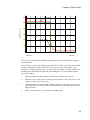
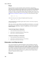
Dedicated menus are supplied for starting a full circle, half circle and quarter circle.
For everything else use Arcs|Ellipse/Arc... .
When you have initiated the operation, the cursor will change to a shape showing a
pencil with a small circle. You can now draw the curved segment by dragging the
mouse with the left key. When you release the mouse button the operation will be
complete and the mouse mode will revert to normal select mode.
It is easier to demonstrate than explain. You may wish to experiment with
arc/circle/ellipse drawing to gain a feel of how the system operates.
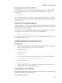
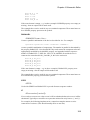
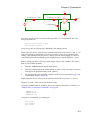
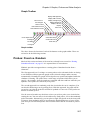
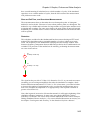
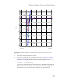
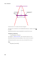
You will note that full circles are displayed with a small filled square on opposite sides.
These are the select points. You can pick either one and drag it to resize the circle.
Placing and Defining Pins
Placing a Single Pin
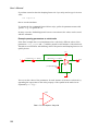
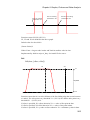
To place a single pin, select Property/Pin|Place Pin... . Place this on the sheet by left
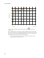
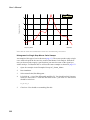
clicking the mouse at your desired location. Note that pins always snap to major grid
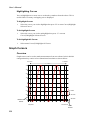
points. (See diagram in section “Symbol Editor Window” on page 91).
The first pin you place on the sheet will be called ‘*pin’. The * signifies that the pin
name will not be visible when the symbol is placed on a schematic.
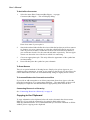
Editing Pin Attributes
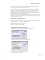
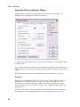
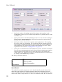
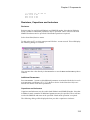
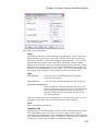
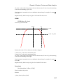
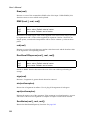
To edit the attributes of the pin, (e.g. to change its name or visibility) select either the
pin or its label with the left mouse key then press F7 or select popup menu
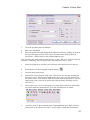
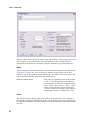
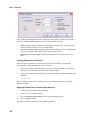
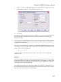
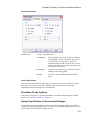
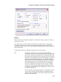
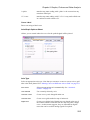
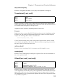
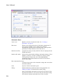
Edit Property/Pin/Arc... . This will display the following dialog:
Pin name
Must be unique within the symbol and may not contain spaces.
93